CN100435411C - Low-height dual-band or multiband antenna, in particular for motor vehicles - Google Patents
Low-height dual-band or multiband antenna, in particular for motor vehicles Download PDFInfo
- Publication number
- CN100435411C CN100435411C CNB038168073A CN03816807A CN100435411C CN 100435411 C CN100435411 C CN 100435411C CN B038168073 A CNB038168073 A CN B038168073A CN 03816807 A CN03816807 A CN 03816807A CN 100435411 C CN100435411 C CN 100435411C
- Authority
- CN
- China
- Prior art keywords
- antenna
- planar
- radiator
- frequency band
- band
- Prior art date
- Legal status (The legal status is an assumption and is not a legal conclusion. Google has not performed a legal analysis and makes no representation as to the accuracy of the status listed.)
- Expired - Fee Related
Links
Images


Classifications
-
- H—ELECTRICITY
- H01—ELECTRIC ELEMENTS
- H01Q—ANTENNAS, i.e. RADIO AERIALS
- H01Q9/00—Electrically-short antennas having dimensions not more than twice the operating wavelength and consisting of conductive active radiating elements
- H01Q9/04—Resonant antennas
- H01Q9/0407—Substantially flat resonant element parallel to ground plane, e.g. patch antenna
- H01Q9/0414—Substantially flat resonant element parallel to ground plane, e.g. patch antenna in a stacked or folded configuration
-
- H—ELECTRICITY
- H01—ELECTRIC ELEMENTS
- H01Q—ANTENNAS, i.e. RADIO AERIALS
- H01Q1/00—Details of, or arrangements associated with, antennas
- H01Q1/12—Supports; Mounting means
- H01Q1/22—Supports; Mounting means by structural association with other equipment or articles
- H01Q1/24—Supports; Mounting means by structural association with other equipment or articles with receiving set
- H01Q1/241—Supports; Mounting means by structural association with other equipment or articles with receiving set used in mobile communications, e.g. GSM
- H01Q1/242—Supports; Mounting means by structural association with other equipment or articles with receiving set used in mobile communications, e.g. GSM specially adapted for hand-held use
- H01Q1/243—Supports; Mounting means by structural association with other equipment or articles with receiving set used in mobile communications, e.g. GSM specially adapted for hand-held use with built-in antennas
-
- H—ELECTRICITY
- H01—ELECTRIC ELEMENTS
- H01Q—ANTENNAS, i.e. RADIO AERIALS
- H01Q5/00—Arrangements for simultaneous operation of antennas on two or more different wavebands, e.g. dual-band or multi-band arrangements
- H01Q5/30—Arrangements for providing operation on different wavebands
- H01Q5/307—Individual or coupled radiating elements, each element being fed in an unspecified way
- H01Q5/342—Individual or coupled radiating elements, each element being fed in an unspecified way for different propagation modes
- H01Q5/357—Individual or coupled radiating elements, each element being fed in an unspecified way for different propagation modes using a single feed point
- H01Q5/364—Creating multiple current paths
- H01Q5/371—Branching current paths
-
- H—ELECTRICITY
- H01—ELECTRIC ELEMENTS
- H01Q—ANTENNAS, i.e. RADIO AERIALS
- H01Q9/00—Electrically-short antennas having dimensions not more than twice the operating wavelength and consisting of conductive active radiating elements
- H01Q9/04—Resonant antennas
- H01Q9/0407—Substantially flat resonant element parallel to ground plane, e.g. patch antenna
- H01Q9/0421—Substantially flat resonant element parallel to ground plane, e.g. patch antenna with a shorting wall or a shorting pin at one end of the element
-
- H—ELECTRICITY
- H01—ELECTRIC ELEMENTS
- H01Q—ANTENNAS, i.e. RADIO AERIALS
- H01Q9/00—Electrically-short antennas having dimensions not more than twice the operating wavelength and consisting of conductive active radiating elements
- H01Q9/04—Resonant antennas
- H01Q9/0407—Substantially flat resonant element parallel to ground plane, e.g. patch antenna
- H01Q9/0471—Non-planar, stepped or wedge-shaped patch
Landscapes
- Engineering & Computer Science (AREA)
- Computer Networks & Wireless Communication (AREA)
- Waveguide Aerials (AREA)
- Details Of Aerials (AREA)
- Support Of Aerials (AREA)
- Variable-Direction Aerials And Aerial Arrays (AREA)
- Transmitters (AREA)
Abstract
Description
本发明涉及主要用于汽车的一种低高双波段或多波段天线。The present invention relates to a low-height dual-band or multi-band antenna mainly used in automobiles.
特别是在德国和欧洲移动无线网中在900MHz或所谓的1800MHz波段内实现通信。特别是在美国在所谓的1900MHz波段范围内进行传输。最近出现的UMTS网络将构造在2000或2100MHz波段范围内。In particular, communication takes place in the German and European mobile radio networks in the 900 MHz or so-called 1800 MHz band. Especially in the United States there is transmission in the so-called 1900MHz band. The UMTS network that appears recently will be constructed in the range of 2000 or 2100MHz band.
在汽车领域中尤其需要低高度的天线,这些天线应该具有尽可能好的电气性能,即特别是具有大的带宽、良好的圆形幅射特性以及紧凑的构造形式。In particular in the automotive sector antennas of low height are required which should have the best possible electrical properties, ie in particular a large bandwidth, good circular radiation characteristics and a compact design.
目前已提出了双波段平面天线,另外它也被称为“堆叠的双频率-微带”PIF天线。A dual-band planar antenna has been proposed, which is also known as a "stacked dual-frequency-microstrip" PIF antenna.
由现有技术已知的这种天线在一个金属底面或底板之上具有一个与底板平行的平面辐射器,此辐射器在其一个长边上通过一个垂直于平面辐射器单元及底板的短接器而与金属底板短路。平面辐射器单元的长度和宽度,以及其大小适配于例如最低传输频率,例如适配于900MHz波段。Antennas of this type known from the prior art have a flat radiator parallel to the bottom on a metallic base or bottom plate, which is connected on one of its long sides by a short-circuit perpendicular to the flat radiator element and the bottom plate. The device is shorted to the metal base. The length and width of the planar radiator unit, as well as its size, are adapted eg to the lowest transmission frequency, eg to the 900 MHz band.
在此基础上构造一个原理上相同的平面辐射器,它用于在较高的频带范围内传输并有相对较小的尺寸。此辐射器与另一个平面辐射器单元一起以整体上更小的纵向和横向长度位于其下具有较大尺寸的平面辐射器单元上最好顶视图的中央位置处,并且它也平行于其下的平面辐射器单元。在此辐射器单元的一个长边上,最好在相同于最低频带范围的平面辐射器单元的长边上通过一个短接器与位于其下的平面辐射器单元相连接。此短接器单元最好也垂直于这两个平面辐射器单元。On this basis, a fundamentally identical planar radiator is constructed, which is used for transmission in the higher frequency band and has relatively small dimensions. This radiator is located together with another flat radiator unit with an overall smaller longitudinal and transverse length in the best top-view central position on the larger dimensioned flat radiator unit below it, and it is also parallel to its lower planar radiator unit. On one long side of the radiator unit, preferably on the same long side as the lowest frequency band range, the planar radiator unit is connected to the planar radiator unit located below it via a short. This short-circuit unit is preferably also perpendicular to the two planar radiator units.
通过一个最好是垂直于这些平面辐射器单元的馈电线实现馈电,它从一个在底板区域内的馈电位置,例如一个匹配网络,与馈电点隔离,馈电线基本垂直地向上引到最上面的平面辐射器单元的底侧面。为此在下面的平面辐射器单元上有一个相应的通孔,以使馈电线引到最上面的平面辐射器单元。The feed is effected via a feed line, preferably perpendicular to the planar radiator elements, from a feed point in the area of the base plate, such as a matching network, isolated from the feed point, the feed line leading substantially vertically upwards to The bottom side of the uppermost planar radiator unit. For this purpose, a corresponding through-opening is provided on the lower planar radiator unit, so that the feed lines lead to the uppermost planar radiator unit.
这种天线已通过实践考验,本发明的目的在于给出一种改进了的面辐射天线,其制造和安装相比至今的方案明显简化。此任务根据本发明这样来完成:Such antennas have proven themselves in practice, and the object of the present invention is to provide an improved surface-radiating antenna whose production and installation are significantly simplified compared to previous solutions. This task is accomplished according to the invention in this way:
根据一个优选实施例,本发明所述的低高度双波段或多波段天线具有以下的一个或多个特征:a)双波段或多波段天线被设置或可定位在一个金属底面或底板上,b)双波段或多波段天线包括至少两个工作在两个不同频带范围的平面辐射器,c)两个平面辐射器相互平行或至少近似平行,d)至少两个平面辐射器的大小从最接近底板的平面辐射器单元到离底面或底板最远的平面辐射器单元减小,e)用于在较高频带范围内传输的平面辐射器与用于在较低频带范围内传输的平面辐射器相连接,f)平面辐射器在其一侧具有一个短接器,使得用于在较高频带范围内传输的平面辐射器通过短接器与用于在较低频带范围内传输的平面辐射器短接,并且用于在最低频带范围内传输的平面辐射器通过短接器连接或可连接于金属底面或底板,g)双波段或多波段天线构造为单构件的冲压弯折金属件,h)天线作为一整块结构具有至少两个平面辐射器,在这两个平面辐射器之间设置有短接器,i)至少用于在最低频带范围内传输和/或用于在相对于较高频带范围而言较低的频带范围内传输的平面辐射器具有与其辐射面相邻的天线翼,它们与相应的辐射面电气连接,并且在天线顶视图中,相应用于在较高频带范围内传输的平面辐射器位于上述天线翼之间,j)用于在较高频带范围内传输的平面辐射器相对于用于在相对较低频带范围内传输的平面辐射器被设置在同一平面或在一个相对于其横向错位的、平行于或至少近似平行于平面辐射器的平面中,并且k)一个从下延伸到最上面的平面辐射器底侧面上的馈电线同样作为冲压弯折件构成,它与如此构成的天线的其余部件一体连接。According to a preferred embodiment, the low-height dual-band or multi-band antenna of the present invention has one or more of the following features: a) the dual-band or multi-band antenna is arranged or can be positioned on a metal bottom or base plate, b ) a dual-band or multi-band antenna comprises at least two planar radiators operating in two different frequency bands, c) the two planar radiators are parallel or at least approximately parallel to each other, d) at least two planar radiators are sized from the nearest The planar radiator unit of the base plate decreases to the planar radiator unit farthest from the base or base plate, e) planar radiators for transmission in the higher frequency band range vs. planar radiators for transmission in the lower frequency band range f) the planar radiator has a short on one side, so that the planar radiator for transmission in the higher frequency band is connected to the plane for transmission in the lower frequency band through the short The radiators are short-circuited, and the planar radiators for transmission in the lowest frequency band are connected or connectable to the metal base or baseplate via short-circuits, g) dual-band or multi-band antennas are constructed as single-component stamped and bent metal parts , h) the antenna as a monolithic structure has at least two planar radiators between which a short-circuiter is arranged, i) at least for transmission in the lowest frequency band and/or for transmission in the relative A planar radiator transmitting in the lower frequency range with respect to the higher frequency band range has antenna wings adjacent to its radiating surface, which are electrically connected to the corresponding radiating surface and, in top view of the antenna, are correspondingly used in the lower frequency range. The planar radiators for transmission in the high frequency band are located between the above-mentioned antenna wings, j) the planar radiators for transmission in the higher frequency band are replaced with respect to the planar radiators for transmission in the relatively lower frequency band Arranged in the same plane or in a plane that is offset laterally relative to it, parallel or at least approximately parallel to the planar radiators, and k) a feed line extending from below to the bottom side of the uppermost planar radiator also serves as It is formed as a stamped and bent part, which is integrally connected with the remaining parts of the antenna thus formed.
连接相邻平面辐射器的电短接器通过两个反向的弯折边与两个平面辐射器连接。An electrical short connecting adjacent planar radiators is connected to the two planar radiators via two opposite bent edges.
最下面的平面辐射器具有构成天线一部分的短接器,它通过弯折线与平面辐射器的辐射面相连接。The lowermost planar radiator has a short-circuit forming part of the antenna, which is connected to the radiating surface of the planar radiator via a meander line.
在最上面的平面辐射器中加工出一个槽形开口,并形成馈电线,馈电线在弯折线上基本垂直于平面辐射器的平面向下弯折。A slot-shaped opening is processed in the uppermost planar radiator to form a feeder line, which is bent downward on the bending line substantially perpendicular to the plane of the planar radiator.
天线翼的终端边缘垂直于天线翼的纵向边缘。The terminal edge of the antenna wing is perpendicular to the longitudinal edge of the antenna wing.
天线翼的终端边缘从外侧边缘向中间会聚或向外发散。The terminal edges of the antenna wings converge toward the middle or diverge outward from the outer edges.
用于较高频带范围的天线辐射器的天线翼的向外伸出的边缘从其有短接器的一侧向其自由端会聚或向外发散。The outwardly protruding edges of the antenna wings of the antenna radiator for the higher frequency band range converge or diverge outward from their short-circuited side towards their free ends.
用于较低传输范围的天线辐射器的天线翼的向内伸出的边缘从其短接器侧向其自由端会聚或向外发散。The inwardly protruding edges of the antenna wings of the antenna radiator for the lower transmission range converge or diverge outward from its short-bar side towards its free end.
短接器具有矩形形状,并且最好在相应天线辐射器的整个宽度上延伸。The short has a rectangular shape and preferably extends over the entire width of the respective antenna radiator.
短接器比天线辐射器的宽度更短。The short is shorter than the width of the antenna radiator.
短接器具有三角形或梯形形状。The shorts have a triangular or trapezoidal shape.
平面辐射器的天线翼被设置在不同高度的水平面上,并且用于在较高频带范围内传输的平面辐射器被设置在用于在相对较低频带范围内传输的平面辐射器的上面。The antenna wings of the planar radiators are arranged at different heights on the horizontal plane, and the planar radiators for transmission in the higher frequency band are arranged above the planar radiators for transmission in the relatively lower frequency band.
至少两个平面辐射器的天线翼位于同一高度线上。The antenna wings of at least two planar radiators are located on the same height line.
天线翼最好在其向外伸出的分界边缘上具有最好指向下面的天线翼区段。The antenna wings preferably have, on their outwardly protruding boundary edges, antenna wing sections, preferably pointing downwards.
天线被构造成三波段天线,其上级联了第三个平面辐射器,其形状被设计成至少类似于另外两个平面辐射器,并且适配于在最高频带范围中传输。The antenna is designed as a three-band antenna, to which a third planar radiator is cascaded, which is shaped at least like the other two planar radiators and is adapted for transmission in the highest frequency band range.
根据本发明的低高度双波段或多波段天线的特征在于,其主要部件由一完整单构件的冲压弯折零件构成。The low-height dual-band or multi-band antenna according to the invention is characterized in that its main parts consist of a single-piece punched and bent part.
换言之,至少两个用于在两个频带范围内传输的平面辐射器单元及一个作用在其间的短接器由一个单独的薄板冲压零件制造并成形。In other words, at least two planar radiator elements for transmission in the two frequency bands and a short-circuit acting therebetween are manufactured and shaped from a single sheet metal stamped part.
在本发明的一个优选实施方式中用于连接最低频带范围平面辐射器单元(即与金属底板相邻的平面辐射器单元)的相应短接器也是完整单构件的冲压弯折零件的一个组成部件,即单构件的平面天线的一个公共组成部件。In a preferred embodiment of the invention the corresponding shorts for connecting the planar radiator units of the lowest frequency range (i.e. the planar radiator units adjacent to the metal base plate) are also an integral part of the complete single-part stamped and bent part , a common component of a single-element planar antenna.
在另一个具有优点的实施方式中,基本垂直于平面辐射器单元的馈电线同样也被设计为冲压弯折零件,并作为完整冲压弯折零件中的一个零件。In a further advantageous embodiment, the feed lines which are substantially perpendicular to the planar radiator unit are likewise designed as stamped and bent parts and are part of a complete stamped and bent part.
整个结构可以多重级联,使得不仅两个、而且至少三个不同尺寸的平面辐射器单元基本平行地相互重叠排列,以使紧凑的天线也可例如作为多波段天线在三个波段范围内发送和接收。The entire structure can be cascaded in multiples, so that not only two, but at least three planar radiator elements of different sizes are arranged substantially parallel to one another, so that the compact antenna can also be used, for example, as a multi-band antenna for transmitting and receiving in three bands. take over.
此外已经表明双波段或多波段天线可以具有多个平面辐射器单元,这些单元不是必须构造在相互不同的高度位置上,而是构造在一个共同的高度位置上,在此情况下两个平面辐射器单元之间的短接器也同样被设置在同一高度线上。It has also been shown that dual-band or multi-band antennas can have a plurality of planar radiator elements, which are not necessarily arranged at mutually different height positions, but at a common height position, in which case two planar radiator elements The shorts between the switch units are also set on the same height line.
这些平面辐射器单元可以基本上在顶视图中具有平行和垂直的切线边缘和弯折边缘。位于较高处、用于在较高频带范围内传输的平面辐射器单元的分别指向外部的冲压边缘也可以构造为例如从其短接处至其自由端略微向外发散或向内会聚,或者尤其在其自由端具有斜向的端边缘区域。位于低处的平面辐射器单元的冲压边缘同样可以构造成斜向的,并且冲压边缘外部与内部一样不是必须平行走向的。These planar radiator units may have substantially parallel and perpendicular tangential and bent edges in top view. The punched-out edges of the planar radiator elements located higher up for transmission in the higher frequency range can also be configured so as to diverge slightly outwards or converge inwards, for example from their short-circuit point to their free ends, Or in particular at its free end it has an oblique end edge region. The stamped edge of the lower planar radiator unit can likewise be formed obliquely, and the stamped edge does not have to run parallel on the outside, just like on the inside.
此外,在本发明的一个优选的实施方式中,天线翼可以通过另一个向下的弯折而被延长。Furthermore, in a preferred embodiment of the invention, the antenna wings can be extended by a further downward bend.
短路连接也不是必须构造在相应面辐射单元的整个宽度上。短路连接可以构造在比相应平面辐射器单元的整个横向长度更短的长度上。It is also not necessary for the short-circuit connection to be formed over the entire width of the respective surface radiation element. The short-circuit connection can be formed over a length that is shorter than the entire transverse length of the corresponding planar radiator unit.
下面借助附图详细说明本发明。附图中:The invention is described in detail below with reference to the drawings. In the attached picture:
图1是第一个双波段天线的第一透视图;Figure 1 is a first perspective view of the first dual-band antenna;
图2是图1所示双波段天线的另一透视图;Fig. 2 is another perspective view of the dual-band antenna shown in Fig. 1;
图3是图1和2所示平面天线的一个相应的后视图;Figure 3 is a corresponding rear view of the planar antenna shown in Figures 1 and 2;
图4是图1至3所示平面天线的一个相应的顶视图;Figure 4 is a corresponding top view of the planar antenna shown in Figures 1 to 3;
图5是金属初轧板(薄板)的顶视图,其上示出用于形成图1至4所示天线的冲压线和弯折线;Figure 5 is a top view of a metal pre-rolled sheet (sheet) showing the punch lines and bend lines used to form the antenna shown in Figures 1 to 4;
图6示出相应平面天线的一个与图1不相同的实施例;Figure 6 shows a different embodiment of the corresponding planar antenna than in Figure 1;
图7是图6所示实施例的顶视图;Figure 7 is a top view of the embodiment shown in Figure 6;
图8是另一个不同的平面天线实施例的透视图;Figure 8 is a perspective view of another different planar antenna embodiment;
图9是图8所示实施例的顶视图;Figure 9 is a top view of the embodiment shown in Figure 8;
图10是另一个不同的实施例的透视图;Figure 10 is a perspective view of another different embodiment;
图11示出具有在相同高度上的天线平面的双波段天线的另一个实施例;Figure 11 shows another embodiment of a dual-band antenna with antenna planes at the same height;
图12是具有向下延长的天线翼的另一个实施例的透视图;Figure 12 is a perspective view of another embodiment with downwardly extending antenna wings;
图13是图12所示实施例的后视图;Figure 13 is a rear view of the embodiment shown in Figure 12;
图14是一个三波段天线的另一个实施例的透视图;以及Figure 14 is a perspective view of another embodiment of a three-band antenna; and
图15是图14所示实施例的侧视图。Figure 15 is a side view of the embodiment shown in Figure 14 .
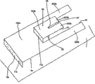
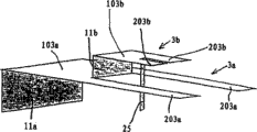
图1至4示出根据本发明的低高度紧凑双波段天线的第一个实施例,它由两个平面辐射器单元或平面辐射器3a和3b构成,这两个平面辐射器相互平行设置。这种天线单元还具有一个面积更大的金属平面或者底板7,即与此底板相连接,或者例如在用于汽车上时相应天线被安装到汽车车身板上相应位置处,车身板在此被用作金属支撑面或底面。1 to 4 show a first embodiment of a low-height compact dual-band antenna according to the invention, which consists of two planar radiator elements or
下面的平面单元,即下面的平面辐射器3a适用于在较低的或低的频带内,例如在900MHz频带范围内传输。上面的较小尺寸的平面辐射器3b适用于例如在1800MHz频带范围内传输。The lower planar unit, ie the lower
上面的平面辐射器3b在其位于图1左侧的窄分界边或分界边缘处通过一个短接器11b与位于它下面的较大尺寸的平面辐射器3a相连接,其中短接器11b在所示实施例中具有与上面的平面辐射器3b相一致的宽度。The upper
下面的平面辐射器3a同样在其位于在侧的窄分界边9a处通过垂直的短接面11a形成与所述电气的底面或底板7的电连接。The lower
此外上面和下面的平面辐射器分别被如此设计:相应平面辐射器单元的一部分由一个封闭的金属面部分103a或103b构成,在其对着短接器11a或11b的一侧上分别连接着两个在天线辐射器单元横向位置上分开设置的天线翼203a或203b。In addition, the upper and lower planar radiators are designed in such a way that a part of the respective planar radiator unit consists of a closed
在所示实旋例中,整个由图1所示的天线由单个的冲压弯折零件形成,然而不包括底板7。图5示出一个金属初轧板,其中点划线表示相应的冲压线19,虚线表示弯折边缘。通过冲压-剪切过程和随后沿着弯折边缘21’a和21’b的弯折可形成用于较高频带范围的平面辐射器单元3b,在平行于下面的平面辐射器单元3a的较高位置处形成,如图3a和3b所示那样。通过弯折过程同时形成垂直于平面辐射器单元平面的短接器11a和11b。In the practical example shown, the entire antenna shown in FIG. 1 is formed from a single stamped and bent part, excluding the base plate 7 however. FIG. 5 shows a metal blank, where the dotted lines indicate the
由图5所示初轧板部件的顶视图可见:在此实施例中只有用×表示的材料区域在冲压过程中必须被切割掉。其余部分只被冲压或沿相应直线被成边和弯折,以形成图1至4所示的双波段天线。It can be seen from the top view of the bloomed sheet part shown in FIG. 5 that in this embodiment only the material regions marked with a x have to be cut out during the punching process. The remaining parts are simply stamped or edged and bent along corresponding straight lines to form the dual band antenna shown in FIGS. 1 to 4 .
此外还需要一个馈电线25,它最好垂直于平面辐射器单元的平面,并从下方延伸到位于上面的平面辐射器单元3b的底侧面。在所示实施例中此馈电线25同样作为冲压弯折零件形成,为此上面的平面辐射器单元3b具有一个槽形开口27,并且下面的槽形开口27的左端构成弯折边缘29,这样窄金属条可垂直向下弯曲而形成所述的馈电线25。Furthermore, a
在图1至4所示实施例中平板形加工材料几乎整个面积都被利用了,因为在上面的平面辐射器单元3b的外侧边31与下面的平面辐射器单元的内侧边33之间只是通过一个冲压线或剪切线19构成,而无需冲压掉材料。在图6和7所示实施例中则不同,在平面辐射器单元横向上相应的短接器11a或11b被设计得较窄,所以在冲压过程和弯折过程中初轧金属板上相应材料区域必须被冲压掉。In the embodiment shown in FIGS. 1 to 4, almost the entire area of the plate-shaped process material is utilized, because between the
此外天线翼203a和203b的向前伸出的端部在其自由端不具有垂直于天线翼纵向方向的终端边缘或剪切边缘35,而是具有斜着从外向内会聚的终端边缘或剪切边缘35。Furthermore, the forwardly protruding ends of the
在图8和9所示实施例中,较高的平面辐射器的外侧剪切边31被设计成从短接器侧到自由端是会聚的,并且此边31平行于较低的平面辐射器单元3a的相应会聚的内侧剪切边33。这样至少对于上面的平面辐射器单元3b形成尖顶状天线翼203b。下面的平面辐射器单元的天线翼203a具有朝其自由端逐渐增大的宽度和扩展。外侧的终端边缘或剪切边缘同样也可设计成会聚的,其中下面的平面辐射器的天线翼203a向前伸出的两个尖端可以相遇或几乎相遇。In the embodiment shown in Figures 8 and 9, the outer trimmed
图10所示实施例中同样作为冲压件或弯折件形成的馈电线段被构造成从上向下逐渐变窄的金属条,即此金属条具有相互不断靠拢、会聚的两个对立的侧冲压边39。相反,短接器11a被设计成从下向上呈梯形,至少对于低频带范围的平面辐射器单元是这样。此外由图11所示实施例可见,用于不同频带范围的天线翼也可被置于一个公共的水平面内,即设置成O形或叉形,从而在此实施例中连接两个平面辐射器单元3b和3a的短接器11b也位于同一水平面上。In the embodiment shown in FIG. 10, the feeder section, which is also formed as a stamped or bent part, is configured as a metal strip that gradually narrows from top to bottom, that is, this metal strip has two opposite sides that are continuously approaching and converging. Stamping
按照所说明的实施例也可构造多波段天线,这时图中所示两个平面辐射器单元的相应级联中例如再补充第三个平面辐射器单元,它的尺寸较小,并以相应同样的方式构造在第二个平面辐射器单元上。在此情况下如此构成的整个天线也可作为冲压件和弯折件被形成,即具有单构件结构。According to the described embodiment, it is also possible to construct a multi-band antenna, in which case a third planar radiator unit is supplemented, for example, in the corresponding cascade of the two planar radiator elements shown in the figure, which is smaller in size and correspondingly Construct in the same way on the second planar radiator unit. In this case, the entire antenna constructed in this way can also be formed as a stamped and bent part, ie has a single-part construction.
下面说明图12和13所示实施例。在此实施例中下面的平面辐射器的天线翼203a具有向下延长的天线翼区段203a’,从而形成以下优点:天线翼203a可以相对于其它实施例被缩短,并且同时提高机械稳定性。在所示实施例中天线翼外侧边上的相应天线翼区段203a’由垂直向下立着的折边金属段构成。Next, the embodiment shown in Figs. 12 and 13 will be described. In this embodiment, the
相应地,用于在较高频带范围中传输的平面辐射器3b的天线翼203b也可可选地或附带地设置这种天线翼区段。Correspondingly, the
图14和15示出适用于在三个不同波段辐射的相应天线类型,在此实施例中,平面辐射器3b的结构相对于前面所说明的那些实施例又级联了一个位于其上的小尺寸平面辐射器3c,它同样具有相应的天线翼。与位于其下面的平面辐射器3b的连接同样通过相应的短接器11c实现。馈电通过馈电线25实现,它一直引到最上面的平面辐射器3c。Figures 14 and 15 show corresponding antenna types suitable for radiation in three different bands. In this embodiment, the structure of the
所述天线涉及到所谓的PIF天线,即所谓的“平面倒F天线”。已经知道,在这种天线中天线性能可能受到实施和馈电点及短接器位置的影响。因此可以通过实施和馈电点及短接器位置使天线性能适配于相应汽车车身和相应安装位置的影响。这里短接器,例如分别位于天线装置的窄侧边上的短接器11a和11b,天线装置结构最好基本纵向对称(对称于垂直的中心纵向平面)。天线的馈电点最好在此纵向对称轴或天线的纵向对称平面上。通过选择馈电点相对于短接器的位置和距离可使天线阻抗适配,天线阻抗在汽车天线中通常应为50Ω。The antenna is a so-called PIF antenna, a so-called "planar inverted-F antenna". It is known that in such antennas the antenna performance can be affected by the implementation and location of the feed point and short. The performance of the antenna can thus be adapted to the influence of the respective vehicle body and the respective installation position by means of the design and the position of the feed point and the short. Here the shorts, eg
Claims (14)
Applications Claiming Priority (2)
| Application Number | Priority Date | Filing Date | Title |
|---|---|---|---|
| DE10231961.8 | 2002-07-15 | ||
| DE10231961A DE10231961B3 (en) | 2002-07-15 | 2002-07-15 | Low-profile dual or multi-band antenna, especially for motor vehicles |
Publications (2)
| Publication Number | Publication Date |
|---|---|
| CN1669181A CN1669181A (en) | 2005-09-14 |
| CN100435411C true CN100435411C (en) | 2008-11-19 |
Family
ID=30009992
Family Applications (1)
| Application Number | Title | Priority Date | Filing Date |
|---|---|---|---|
| CNB038168073A Expired - Fee Related CN100435411C (en) | 2002-07-15 | 2003-06-12 | Low-height dual-band or multiband antenna, in particular for motor vehicles |
Country Status (10)
| Country | Link |
|---|---|
| US (1) | US7158082B2 (en) |
| EP (1) | EP1522120B1 (en) |
| JP (1) | JP4156590B2 (en) |
| CN (1) | CN100435411C (en) |
| AT (1) | ATE306128T1 (en) |
| AU (1) | AU2003245936A1 (en) |
| BR (1) | BR0312716A (en) |
| DE (2) | DE10231961B3 (en) |
| ES (1) | ES2247548T3 (en) |
| WO (1) | WO2004008573A1 (en) |
Families Citing this family (42)
| Publication number | Priority date | Publication date | Assignee | Title |
|---|---|---|---|---|
| JP4160944B2 (en) * | 2004-10-12 | 2008-10-08 | アルプス電気株式会社 | Antenna device |
| DE102005031329A1 (en) * | 2005-02-19 | 2006-08-24 | Hirschmann Electronics Gmbh | Dual-band ultra-flat antenna for satellite communication |
| DE102005010895B4 (en) * | 2005-03-09 | 2007-02-08 | Fraunhofer-Gesellschaft zur Förderung der angewandten Forschung e.V. | Aperture-coupled antenna |
| DE102005010894B4 (en) * | 2005-03-09 | 2008-06-12 | Fraunhofer-Gesellschaft zur Förderung der angewandten Forschung e.V. | Planar multiband antenna |
| TWI282189B (en) * | 2006-05-19 | 2007-06-01 | Arcadyan Technology Corp | Inverted-F antenna and manufacturing method thereof |
| CN1933240B (en) * | 2006-10-12 | 2010-07-28 | 上海交通大学 | Planar Inverted-F Multi-Frequency Antenna |
| US8934984B2 (en) | 2007-05-31 | 2015-01-13 | Cochlear Limited | Behind-the-ear (BTE) prosthetic device with antenna |
| EP2028720B1 (en) | 2007-08-23 | 2012-11-07 | Research In Motion Limited | Multi-band antenna, and associated methodology, for a radio communication device |
| US7719470B2 (en) | 2007-08-23 | 2010-05-18 | Research In Motion Limited | Multi-band antenna, and associated methodology, for a radio communication device |
| CN101651253B (en) * | 2008-08-11 | 2014-09-10 | 深圳富泰宏精密工业有限公司 | Dual-band antenna and wireless communication device using same |
| DE102009041166B4 (en) * | 2009-09-11 | 2020-03-05 | Bayerische Motoren Werke Aktiengesellschaft | Vehicle antenna for receiving and / or sending radio signals |
| DE102009048229B4 (en) * | 2009-10-05 | 2021-01-21 | Sennheiser Electronic Gmbh & Co. Kg | Antenna unit for wireless audio transmission |
| GB2474117B (en) * | 2009-10-05 | 2013-01-09 | Sennheiser Electronic | Antenna unit for wireless audio transmission |
| DK2458675T3 (en) | 2010-10-12 | 2018-01-22 | Gn Hearing As | Hearing aid with antenna |
| EP2458674A3 (en) | 2010-10-12 | 2014-04-09 | GN ReSound A/S | An antenna system for a hearing aid |
| CN103348532B (en) * | 2011-02-18 | 2016-03-30 | 莱尔德技术股份有限公司 | There is multi-band planar inverted-f antenna (PIFA) and the system of the isolation of improvement |
| DK201270411A (en) * | 2012-07-06 | 2014-01-07 | Gn Resound As | BTE hearing aid having two driven antennas |
| US9554219B2 (en) | 2012-07-06 | 2017-01-24 | Gn Resound A/S | BTE hearing aid having a balanced antenna |
| DK201270410A (en) | 2012-07-06 | 2014-01-07 | Gn Resound As | BTE hearing aid with an antenna partition plane |
| GB2506100B (en) * | 2012-07-06 | 2016-09-07 | Qioptiq Ltd | Mounting an optical component in an optical arrangement |
| US9237404B2 (en) | 2012-12-28 | 2016-01-12 | Gn Resound A/S | Dipole antenna for a hearing aid |
| EP2994956B1 (en) | 2013-05-09 | 2018-11-07 | Microsemi Corp. - High Performance Timing | Planar inverted-f wing antenna for wireless culinary appliances |
| US9686621B2 (en) | 2013-11-11 | 2017-06-20 | Gn Hearing A/S | Hearing aid with an antenna |
| US9408003B2 (en) | 2013-11-11 | 2016-08-02 | Gn Resound A/S | Hearing aid with an antenna |
| US9883295B2 (en) | 2013-11-11 | 2018-01-30 | Gn Hearing A/S | Hearing aid with an antenna |
| US9237405B2 (en) | 2013-11-11 | 2016-01-12 | Gn Resound A/S | Hearing aid with an antenna |
| EP2884580B1 (en) | 2013-12-12 | 2019-10-09 | Electrolux Appliances Aktiebolag | Antenna arrangement and kitchen apparatus |
| US10595138B2 (en) | 2014-08-15 | 2020-03-17 | Gn Hearing A/S | Hearing aid with an antenna |
| CN105742793B (en) * | 2014-12-12 | 2018-11-16 | 青岛海尔电子有限公司 | A kind of double wideband complementary type antennas |
| DE102016109156B4 (en) * | 2016-05-18 | 2019-10-10 | Kathrein Automotive Gmbh | Radiator unit and antenna arrangement, in particular for a motor vehicle with such a radiator unit |
| US10826182B2 (en) * | 2016-10-12 | 2020-11-03 | Carrier Corporation | Through-hole inverted sheet metal antenna |
| US10522915B2 (en) * | 2017-02-01 | 2019-12-31 | Shure Acquisition Holdings, Inc. | Multi-band slotted planar antenna |
| US20200106194A1 (en) * | 2017-05-30 | 2020-04-02 | Hitachi Metals, Ltd. | Planar array antenna and wireless communication module |
| US20190044236A1 (en) * | 2017-08-02 | 2019-02-07 | Pc-Tel, Inc. | One-piece dual-band antenna and ground plane |
| US10797392B2 (en) * | 2017-10-02 | 2020-10-06 | Sensus Spectrum, Llc | Folded, three dimensional (3D) antennas and related devices |
| EP3884544A4 (en) * | 2019-01-30 | 2022-08-17 | AVX Antenna, Inc. D/B/A Ethertronics, Inc. | ANTENNA SYSTEM WITH STACKED ANTENNA STRUCTURES |
| CN110518336A (en) * | 2019-08-27 | 2019-11-29 | 南京邮电大学 | A kind of omnidirectional radiation car antenna |
| DE102021203543B3 (en) * | 2021-04-09 | 2022-08-25 | Continental Automotive Technologies GmbH | Antenna device for a mobile radio device |
| JP2023102414A (en) * | 2022-01-12 | 2023-07-25 | ソニーグループ株式会社 | Antenna device, antenna module, and radio |
| JP7748911B2 (en) * | 2022-04-18 | 2025-10-03 | 日本航空電子工業株式会社 | Multi-band Antenna |
| WO2023234436A1 (en) * | 2022-05-31 | 2023-12-07 | 엘지전자 주식회사 | Wideband antenna arranged on vehicle |
| CN115149238B (en) * | 2022-07-27 | 2025-07-11 | 国网经济技术研究院有限公司 | A multi-frequency antenna for multi-network integration deployment in urban underground integrated pipeline corridors |
Citations (3)
| Publication number | Priority date | Publication date | Assignee | Title |
|---|---|---|---|---|
| GB2288284A (en) * | 1994-04-01 | 1995-10-11 | France Telecom | Antenna with a radiating element and a shaped resonating element |
| CN1207004A (en) * | 1997-05-09 | 1999-02-03 | 摩托罗拉公司 | Radio telephone with differential driving various antenna structure and driving method |
| US6310586B1 (en) * | 2000-03-02 | 2001-10-30 | Alps Electric Co., Ltd. | Wideband antenna mountable in vehicle cabin |
Family Cites Families (13)
| Publication number | Priority date | Publication date | Assignee | Title |
|---|---|---|---|---|
| US4162499A (en) * | 1977-10-26 | 1979-07-24 | The United States Of America As Represented By The Secretary Of The Army | Flush-mounted piggyback microstrip antenna |
| FR2552938B1 (en) * | 1983-10-04 | 1986-02-28 | Dassault Electronique | RADIANT DEVICE WITH IMPROVED MICRO-TAPE STRUCTURE AND APPLICATION TO AN ADAPTIVE ANTENNA |
| JPH03166803A (en) * | 1989-11-27 | 1991-07-18 | Kokusai Denshin Denwa Co Ltd <Kdd> | Microstrip antenna for separately feeding two-frequency circular polarized wave |
| US5355142A (en) * | 1991-10-15 | 1994-10-11 | Ball Corporation | Microstrip antenna structure suitable for use in mobile radio communications and method for making same |
| FR2699740B1 (en) | 1992-12-23 | 1995-03-03 | Patrice Brachat | Broadband antenna with reduced overall dimensions, and corresponding transmitting and / or receiving device. |
| DE69628392T2 (en) * | 1995-11-29 | 2004-03-11 | Ntt Mobile Communications Network Inc. | Antenna with two resonance frequencies |
| FI110395B (en) * | 1997-03-25 | 2003-01-15 | Nokia Corp | Broadband antenna is provided with short-circuited microstrips |
| JP2000068736A (en) * | 1998-08-21 | 2000-03-03 | Toshiba Corp | Multi-frequency antenna |
| DE19929689A1 (en) * | 1999-06-29 | 2001-01-11 | Siemens Ag | Integrable dual band antenna |
| FR2825837B1 (en) * | 2001-06-12 | 2006-09-08 | Cit Alcatel | MULTIBAND COMPACT ANTENNA |
| US6456243B1 (en) * | 2001-06-26 | 2002-09-24 | Ethertronics, Inc. | Multi frequency magnetic dipole antenna structures and methods of reusing the volume of an antenna |
| JP2003101336A (en) * | 2001-09-26 | 2003-04-04 | Furukawa Electric Co Ltd:The | Dual frequency band antenna |
| US6882318B2 (en) * | 2002-03-04 | 2005-04-19 | Siemens Information & Communications Mobile, Llc | Broadband planar inverted F antenna |
-
2002
- 2002-07-15 DE DE10231961A patent/DE10231961B3/en not_active Expired - Fee Related
-
2003
- 2003-06-12 AU AU2003245936A patent/AU2003245936A1/en not_active Abandoned
- 2003-06-12 AT AT03738023T patent/ATE306128T1/en not_active IP Right Cessation
- 2003-06-12 BR BR0312716-8A patent/BR0312716A/en not_active IP Right Cessation
- 2003-06-12 JP JP2004520391A patent/JP4156590B2/en not_active Expired - Fee Related
- 2003-06-12 US US10/521,094 patent/US7158082B2/en not_active Expired - Lifetime
- 2003-06-12 CN CNB038168073A patent/CN100435411C/en not_active Expired - Fee Related
- 2003-06-12 ES ES03738023T patent/ES2247548T3/en not_active Expired - Lifetime
- 2003-06-12 WO PCT/EP2003/006199 patent/WO2004008573A1/en not_active Ceased
- 2003-06-12 EP EP03738023A patent/EP1522120B1/en not_active Expired - Lifetime
- 2003-06-12 DE DE50301327T patent/DE50301327D1/en not_active Expired - Lifetime
Patent Citations (3)
| Publication number | Priority date | Publication date | Assignee | Title |
|---|---|---|---|---|
| GB2288284A (en) * | 1994-04-01 | 1995-10-11 | France Telecom | Antenna with a radiating element and a shaped resonating element |
| CN1207004A (en) * | 1997-05-09 | 1999-02-03 | 摩托罗拉公司 | Radio telephone with differential driving various antenna structure and driving method |
| US6310586B1 (en) * | 2000-03-02 | 2001-10-30 | Alps Electric Co., Ltd. | Wideband antenna mountable in vehicle cabin |
Also Published As
| Publication number | Publication date |
|---|---|
| JP2005539415A (en) | 2005-12-22 |
| EP1522120A1 (en) | 2005-04-13 |
| DE50301327D1 (en) | 2006-02-16 |
| HK1080998A1 (en) | 2006-05-04 |
| US20060012524A1 (en) | 2006-01-19 |
| BR0312716A (en) | 2005-04-19 |
| AU2003245936A1 (en) | 2004-02-02 |
| WO2004008573A1 (en) | 2004-01-22 |
| ATE306128T1 (en) | 2005-10-15 |
| EP1522120B1 (en) | 2005-10-05 |
| US7158082B2 (en) | 2007-01-02 |
| JP4156590B2 (en) | 2008-09-24 |
| DE10231961B3 (en) | 2004-02-12 |
| ES2247548T3 (en) | 2006-03-01 |
| CN1669181A (en) | 2005-09-14 |
Similar Documents
| Publication | Publication Date | Title |
|---|---|---|
| CN100435411C (en) | Low-height dual-band or multiband antenna, in particular for motor vehicles | |
| EP1096602B1 (en) | Planar antenna | |
| US7352326B2 (en) | Multiband planar antenna | |
| CN102694261B (en) | Antenna module | |
| CN107078382B (en) | Multi-Structure Broadband Monopole Antennas for Motor Vehicles | |
| KR101622170B1 (en) | External antenna for vehicle | |
| CN103094669A (en) | Mobile communication terminal | |
| US20080204328A1 (en) | Dual antenna apparatus and methods | |
| US20040169611A1 (en) | Multi-band planar antenna | |
| CN104022358B (en) | Miniaturized multiband antenna | |
| CN102422484A (en) | Antenna combination | |
| EP1459410B1 (en) | High-bandwidth multi-band antenna | |
| JP2005130415A (en) | Glass antenna for vehicle | |
| CN112864589B (en) | Antenna structure and communication device | |
| JP4623272B2 (en) | Antenna device | |
| KR101379123B1 (en) | Wideband Single Resonance Antenna | |
| CN112740479A (en) | Vehicle-mounted antenna device | |
| TWI747538B (en) | Antenna system | |
| EP2302732B1 (en) | Multi-frequency antenna | |
| EP3154125B1 (en) | Eight-frequency band antenna | |
| EP3154124B1 (en) | Ten-frequency band antenna | |
| CN110797635A (en) | Ultra-wideband multi-frequency antenna | |
| HK1080998B (en) | Low-height dual or multi-band antenna, in particular for motor vehicles | |
| CN104078764B (en) | A kind of ultra broadband low-frequency range deformation PIFA for being applied to body area network | |
| KR101657408B1 (en) | Antenna for Multi Band |
Legal Events
| Date | Code | Title | Description |
|---|---|---|---|
| C06 | Publication | ||
| PB01 | Publication | ||
| C10 | Entry into substantive examination | ||
| SE01 | Entry into force of request for substantive examination | ||
| REG | Reference to a national code |
Ref country code: HK Ref legal event code: DE Ref document number: 1080998 Country of ref document: HK |
|
| C14 | Grant of patent or utility model | ||
| GR01 | Patent grant | ||
| REG | Reference to a national code |
Ref country code: HK Ref legal event code: GR Ref document number: 1080998 Country of ref document: HK |
|
| TR01 | Transfer of patent right | ||
| TR01 | Transfer of patent right |
Effective date of registration: 20190219 Address after: Rosenheim Patentee after: Catherine Euro Holdings Address before: Rosenheim Patentee before: KATHREIN-WERKE KG |
|
| TR01 | Transfer of patent right | ||
| TR01 | Transfer of patent right |
Effective date of registration: 20190726 Address after: Hildesheim Patentee after: Kesslin Automobile Co., Ltd. Address before: Rosenheim Patentee before: Catherine Euro Holdings |
|
| CF01 | Termination of patent right due to non-payment of annual fee |
Granted publication date: 20081119 Termination date: 20200612 |
|
| CF01 | Termination of patent right due to non-payment of annual fee |