CN100435503C - optical transmission line - Google Patents
optical transmission line Download PDFInfo
- Publication number
- CN100435503C CN100435503C CNB021273863A CN02127386A CN100435503C CN 100435503 C CN100435503 C CN 100435503C CN B021273863 A CNB021273863 A CN B021273863A CN 02127386 A CN02127386 A CN 02127386A CN 100435503 C CN100435503 C CN 100435503C
- Authority
- CN
- China
- Prior art keywords
- core
- dispersion
- refractive index
- fiber
- cladding
- Prior art date
- Legal status (The legal status is an assumption and is not a legal conclusion. Google has not performed a legal analysis and makes no representation as to the accuracy of the status listed.)
- Expired - Fee Related
Links
- 230000005540 biological transmission Effects 0.000 title claims abstract description 175
- 230000003287 optical effect Effects 0.000 title claims abstract description 58
- 239000006185 dispersion Substances 0.000 claims abstract description 318
- 239000000835 fiber Substances 0.000 claims abstract description 125
- 239000013307 optical fiber Substances 0.000 claims abstract description 96
- 238000005253 cladding Methods 0.000 claims description 91
- 238000005452 bending Methods 0.000 claims description 32
- 238000009826 distribution Methods 0.000 claims description 30
- 230000010287 polarization Effects 0.000 claims description 12
- 239000010410 layer Substances 0.000 description 12
- 238000004519 manufacturing process Methods 0.000 description 11
- 238000004088 simulation Methods 0.000 description 11
- 230000001186 cumulative effect Effects 0.000 description 9
- 238000010586 diagram Methods 0.000 description 5
- 238000000034 method Methods 0.000 description 4
- 238000011835 investigation Methods 0.000 description 3
- 239000012792 core layer Substances 0.000 description 2
- 238000013461 design Methods 0.000 description 2
- 238000005516 engineering process Methods 0.000 description 2
- 238000011160 research Methods 0.000 description 2
- 230000001629 suppression Effects 0.000 description 2
- 238000001069 Raman spectroscopy Methods 0.000 description 1
- 230000009286 beneficial effect Effects 0.000 description 1
- 238000004891 communication Methods 0.000 description 1
- 238000011161 development Methods 0.000 description 1
- 230000003993 interaction Effects 0.000 description 1
- 238000005259 measurement Methods 0.000 description 1
- 230000009022 nonlinear effect Effects 0.000 description 1
- 230000002250 progressing effect Effects 0.000 description 1
- 230000035945 sensitivity Effects 0.000 description 1
Images


Classifications
-
- G—PHYSICS
- G02—OPTICS
- G02B—OPTICAL ELEMENTS, SYSTEMS OR APPARATUS
- G02B6/00—Light guides; Structural details of arrangements comprising light guides and other optical elements, e.g. couplings
- G02B6/02—Optical fibres with cladding with or without a coating
- G02B6/036—Optical fibres with cladding with or without a coating core or cladding comprising multiple layers
- G02B6/03616—Optical fibres characterised both by the number of different refractive index layers around the central core segment, i.e. around the innermost high index core layer, and their relative refractive index difference
- G02B6/03638—Optical fibres characterised both by the number of different refractive index layers around the central core segment, i.e. around the innermost high index core layer, and their relative refractive index difference having 3 layers only
- G02B6/03644—Optical fibres characterised both by the number of different refractive index layers around the central core segment, i.e. around the innermost high index core layer, and their relative refractive index difference having 3 layers only arranged - + -
-
- G—PHYSICS
- G02—OPTICS
- G02B—OPTICAL ELEMENTS, SYSTEMS OR APPARATUS
- G02B6/00—Light guides; Structural details of arrangements comprising light guides and other optical elements, e.g. couplings
- G02B6/02—Optical fibres with cladding with or without a coating
- G02B6/02004—Optical fibres with cladding with or without a coating characterised by the core effective area or mode field radius
- G02B6/02009—Large effective area or mode field radius, e.g. to reduce nonlinear effects in single mode fibres
- G02B6/02014—Effective area greater than 60 square microns in the C band, i.e. 1530-1565 nm
-
- G—PHYSICS
- G02—OPTICS
- G02B—OPTICAL ELEMENTS, SYSTEMS OR APPARATUS
- G02B6/00—Light guides; Structural details of arrangements comprising light guides and other optical elements, e.g. couplings
- G02B6/02—Optical fibres with cladding with or without a coating
- G02B6/02214—Optical fibres with cladding with or without a coating tailored to obtain the desired dispersion, e.g. dispersion shifted, dispersion flattened
- G02B6/02219—Characterised by the wavelength dispersion properties in the silica low loss window around 1550 nm, i.e. S, C, L and U bands from 1460-1675 nm
- G02B6/02228—Dispersion flattened fibres, i.e. having a low dispersion variation over an extended wavelength range
- G02B6/02238—Low dispersion slope fibres
- G02B6/02242—Low dispersion slope fibres having a dispersion slope <0.06 ps/km/nm2
-
- G—PHYSICS
- G02—OPTICS
- G02B—OPTICAL ELEMENTS, SYSTEMS OR APPARATUS
- G02B6/00—Light guides; Structural details of arrangements comprising light guides and other optical elements, e.g. couplings
- G02B6/02—Optical fibres with cladding with or without a coating
- G02B6/036—Optical fibres with cladding with or without a coating core or cladding comprising multiple layers
- G02B6/03616—Optical fibres characterised both by the number of different refractive index layers around the central core segment, i.e. around the innermost high index core layer, and their relative refractive index difference
- G02B6/03622—Optical fibres characterised both by the number of different refractive index layers around the central core segment, i.e. around the innermost high index core layer, and their relative refractive index difference having 2 layers only
- G02B6/03633—Optical fibres characterised both by the number of different refractive index layers around the central core segment, i.e. around the innermost high index core layer, and their relative refractive index difference having 2 layers only arranged - -
-
- G—PHYSICS
- G02—OPTICS
- G02B—OPTICAL ELEMENTS, SYSTEMS OR APPARATUS
- G02B6/00—Light guides; Structural details of arrangements comprising light guides and other optical elements, e.g. couplings
- G02B6/24—Coupling light guides
- G02B6/26—Optical coupling means
- G02B6/28—Optical coupling means having data bus means, i.e. plural waveguides interconnected and providing an inherently bidirectional system by mixing and splitting signals
- G02B6/293—Optical coupling means having data bus means, i.e. plural waveguides interconnected and providing an inherently bidirectional system by mixing and splitting signals with wavelength selective means
- G02B6/29371—Optical coupling means having data bus means, i.e. plural waveguides interconnected and providing an inherently bidirectional system by mixing and splitting signals with wavelength selective means operating principle based on material dispersion
- G02B6/29374—Optical coupling means having data bus means, i.e. plural waveguides interconnected and providing an inherently bidirectional system by mixing and splitting signals with wavelength selective means operating principle based on material dispersion in an optical light guide
- G02B6/29376—Optical coupling means having data bus means, i.e. plural waveguides interconnected and providing an inherently bidirectional system by mixing and splitting signals with wavelength selective means operating principle based on material dispersion in an optical light guide coupling light guides for controlling wavelength dispersion, e.g. by concatenation of two light guides having different dispersion properties
- G02B6/29377—Optical coupling means having data bus means, i.e. plural waveguides interconnected and providing an inherently bidirectional system by mixing and splitting signals with wavelength selective means operating principle based on material dispersion in an optical light guide coupling light guides for controlling wavelength dispersion, e.g. by concatenation of two light guides having different dispersion properties controlling dispersion around 1550 nm, i.e. S, C, L and U bands from 1460-1675 nm
-
- G—PHYSICS
- G02—OPTICS
- G02B—OPTICAL ELEMENTS, SYSTEMS OR APPARATUS
- G02B6/00—Light guides; Structural details of arrangements comprising light guides and other optical elements, e.g. couplings
- G02B6/02—Optical fibres with cladding with or without a coating
- G02B6/02214—Optical fibres with cladding with or without a coating tailored to obtain the desired dispersion, e.g. dispersion shifted, dispersion flattened
- G02B6/02285—Characterised by the polarisation mode dispersion [PMD] properties, e.g. for minimising PMD
-
- G—PHYSICS
- G02—OPTICS
- G02B—OPTICAL ELEMENTS, SYSTEMS OR APPARATUS
- G02B6/00—Light guides; Structural details of arrangements comprising light guides and other optical elements, e.g. couplings
- G02B6/02—Optical fibres with cladding with or without a coating
- G02B6/028—Optical fibres with cladding with or without a coating with core or cladding having graded refractive index
- G02B6/0281—Graded index region forming part of the central core segment, e.g. alpha profile, triangular, trapezoidal core
Landscapes
- Physics & Mathematics (AREA)
- Chemical & Material Sciences (AREA)
- Dispersion Chemistry (AREA)
- General Physics & Mathematics (AREA)
- Optics & Photonics (AREA)
- Optical Communication System (AREA)
- Optical Fibers, Optical Fiber Cores, And Optical Fiber Bundles (AREA)
Abstract
本发明涉及光传输线路。本发明提供将多根光纤组合构成的,适合长距离高速大容量传输的超低损耗的色散管理线路。该进行色散管理的光传输线路包含前段的具有正色散和正色散斜率的正色散光纤以及后段落的具有负色散和负色散斜率的负色散光纤,并且在1.55μm波段具有大致为零的色散,其中正色散光纤与负色散光纤在1.55μm波段的传输损耗均为0.23dB/km以下,两光纤的损耗差小于0.05dB/km。

The present invention relates to optical transmission lines. The invention provides an ultra-low loss dispersion management circuit which is composed of multiple optical fibers and is suitable for long-distance, high-speed and large-capacity transmission. The optical transmission line for dispersion management includes a positive dispersion fiber with positive dispersion and a positive dispersion slope in the front section and a negative dispersion fiber with negative dispersion and a negative dispersion slope in the rear section, and has approximately zero dispersion in the 1.55 μm waveband, where The transmission losses of the positive dispersion fiber and the negative dispersion fiber in the 1.55μm band are both less than 0.23dB/km, and the loss difference between the two fibers is less than 0.05dB/km.
Description
技术领域 technical field
本发明涉及用于波分复用(WMD)光纤和该光纤构成的光传输线路。The present invention relates to an optical fiber for wavelength division multiplexing (WMD) and an optical transmission line formed by the optical fiber.
背景技术 Background technique
采用光纤的光传输高速大容量化正在不断发展,波分复用(WMD)传输技术在其付诸实用之际,作为重要技术受到关注。然而,光纤中光信号的高功率化和信号波长间的相互作用造成的非线性现象成为新的问题。High-speed and large-capacity optical transmission using optical fibers is progressing, and wavelength division multiplexing (WMD) transmission technology is attracting attention as an important technology when it is put into practical use. However, nonlinear phenomena caused by the high power of optical signals in optical fibers and the interaction between signal wavelengths have become new problems.
即使非线性现象中,4频调制(FWM)在进行WDM传输时也影响重大,正在积极研究其抑制方法。FMW在色散小时比较显著,因而色散小的光纤在这方面不利,这一点是公知的。即使历来一直使用良好的NZ-DSF(色散绝对值2~8ps/nm/km左右)这方面也不够好。Even among nonlinear phenomena, 4-frequency modulation (FWM) has a great influence on WDM transmission, and its suppression method is being actively studied. It is well known that FMW is noticeable when the dispersion is small, and that an optical fiber with small dispersion is disadvantageous in this regard. Even the good NZ-DSF (about 2-8 ps/nm/km absolute value of dispersion) which has been used all the time is not good enough in this respect.
SPM和XPM带来的波形失真也是很重大的问题。SPM和XPM产生的信号失真φNL一般用下面的式(I)表示。在下面的式(I)中,n2表示非线性折射率,Aeff表示有效纤芯截面积,λ表示传输的光线的波长。Waveform distortion caused by SPM and XPM is also a significant problem. The signal distortion φ NL generated by SPM and XPM is generally represented by the following formula (I). In the following formula (I), n 2 represents the nonlinear refractive index, A eff represents the effective core cross-sectional area, and λ represents the wavelength of the transmitted light.
φNL=(2λn2×Leff×P)/(Aeff)……(I)φ NL =(2λn 2 ×L eff ×P)/(A eff )...(I)
因此,与OFC’97TuN1b等报告的减小非线性折射率n2的研究同时,早已研究OFC’96WK15和OFC’97TuN2所报告那样的有效纤芯截面积Aeff的扩大。然而,判明Aeff的扩大在已有的NZ-DSF之类单一传输线路结构型光纤中,容易产生弯曲损耗增大和色散斜率增大等问题,因而NZ-DSF系统的光传输线路在这方面也有问题。Therefore, in parallel with the reduction of the nonlinear refractive index n 2 reported by OFC'97TuN1b et al., the expansion of the effective core cross-sectional area A eff as reported by OFC'96WK15 and OFC'97TuN2 has already been studied. However, it is found that the expansion of A eff is prone to problems such as increased bending loss and increased dispersion slope in the existing NZ-DSF single transmission line structure optical fiber, so the optical transmission line of the NZ-DSF system also has problems in this respect. question.
为了解决上述问题,提出在采用光纤的整个光传输线路中管理色散的方法有效的建议。In order to solve the above-mentioned problems, it is proposed to be effective in a method of managing dispersion in the entire optical transmission line using an optical fiber.
例如,日本国特开平9-211511号公报揭示了按照低非线性光纤、高非线性光纤的顺序连接具有正负相反符号的色散的光纤,则可得最佳光传输线路的情况。如ECOC’97卷1第127页所记载的具体例那样,提出具有正色散特性的单模光纤(SMF)和具有相反(负)色散特性的的线路用色散补偿光纤(RDF)。这种单模光纤(SMF)和RDF具有色散值的绝对值为16~22ps/nm/km左右的大局部色散,因而在抑制FWM方面有利。For example, Japanese Patent Application Laid-Open No. 9-211511 discloses that an optimal optical transmission line can be obtained by connecting optical fibers having dispersions with opposite signs in the order of low nonlinear fibers and high nonlinear fibers. As a specific example described in ECOC'97 Vol. 1, p. 127, a single-mode fiber (SMF) having a positive dispersion characteristic and a dispersion-compensating fiber (RDF) for lines having an opposite (negative) dispersion characteristic are proposed. Such single-mode fiber (SMF) and RDF have large local dispersion with an absolute value of dispersion value of about 16 to 22 ps/nm/km, and thus are advantageous in suppressing FWM.
然而,虽然采用上述SMF和RDF时能抑制FWM,但在长度方向不断累积16ps/nm/km以上的色散值,因而光传输线路上产生色散造成的波形失真。这样大的累积色散值在高速传输时尤其成为大问题。However, although FWM can be suppressed when the above-mentioned SMF and RDF are used, the dispersion value of 16 ps/nm/km or more is continuously accumulated in the length direction, so that waveform distortion caused by dispersion occurs on the optical transmission line. Such a large cumulative dispersion value becomes a big problem especially in high-speed transmission.
具有这样大的色散值的RDF通常传输损耗高达0.24dB/km以上,而且容易发生长波长侧传输损耗增大的问题。这种RDF还存在极化模色散PMD通常也在
这样,NZ-DSF系统光传输线路以及采用SMF和RDF的(SMF+RDF)类光传输线路都存在上述问题。In this way, both the NZ-DSF system optical transmission line and the (SMF+RDF) type optical transmission line using SMF and RDF have the above-mentioned problems.
发明内容 Contents of the invention
本发明的目的在于解决非线性现象和传输损耗的问题,提供新型低损耗的色散管理线路。The purpose of the invention is to solve the problems of nonlinear phenomenon and transmission loss, and provide a novel low-loss dispersion management circuit.
本发明第一方面的光传输线路,包含具有正色散和正色散斜率的正色散光纤、以及具有负色散和负色散斜率的负色散光纤的光传输线路;其特征在于,The optical transmission line of the first aspect of the present invention comprises a positive dispersion optical fiber with positive dispersion and a positive dispersion slope, and an optical transmission line with a negative dispersion optical fiber with negative dispersion and a negative dispersion slope; it is characterized in that,
所述正色散光纤与所述负色散光纤的1.55μm波段的传输损耗均为0.23kB/km以下,所述正色散光纤与所述负色散光纤的传输损耗差为0.05dB/km以下,The transmission loss of the 1.55 μm band of the positive dispersion fiber and the negative dispersion fiber is less than 0.23 kB/km, and the transmission loss difference between the positive dispersion fiber and the negative dispersion fiber is less than 0.05 dB/km,
所述正色散光纤具有中纤芯、在该中纤芯外周形成的旁纤芯和在该旁纤芯外周形成的包层;The positive dispersion fiber has a central core, a side core formed around the middle core, and a cladding formed around the side core;
所述中纤芯的折射率大于所述旁纤芯的折射率,在该旁纤芯外周形成的包层;The refractive index of the middle core is greater than the refractive index of the side core, and the cladding is formed on the periphery of the side core;
所述包层的折射率、所述旁纤芯的折射率和所述中纤芯的折射率,其分布以阶梯型结构构成;The refractive index of the cladding, the refractive index of the side core and the refractive index of the middle core are distributed in a stepped structure;
所述包层与所述中纤芯之间的相对折射率差Δ1为0.30%至0.50%;The relative refractive index difference Δ1 between the cladding and the middle core is 0.30% to 0.50%;
所述包层与所述旁纤芯之间的相对折射率差Δ2为0.05%至0.25%;The relative refractive index difference Δ2 between the cladding and the side core is 0.05% to 0.25%;
所述旁纤芯的直径b与所述中纤芯的直径a的比例b/a为1.8~2.7倍,The ratio b/a of the diameter b of the side core to the diameter a of the middle core is 1.8 to 2.7 times,
所述负色散光纤用W+分段纤芯型结构构成,The negative dispersion fiber is composed of a W+ segmented core structure,
包层与中纤芯之间的相对折射率差Δ1为0.75%至0.95%;The relative refractive index difference Δ1 between the cladding and the core is 0.75% to 0.95%;
包层与旁纤芯之间的相对折射率差Δ2为-0.45%至-0.35%;The relative refractive index difference Δ2 between the cladding and the side core is -0.45% to -0.35%;
包层与分段纤芯之间的相对折射率差Δ3为0.15%至0.25%;The relative refractive index difference Δ3 between the cladding and the segmented core is 0.15% to 0.25%;
所述中纤芯的直径a、所述旁纤芯的直径b和所述分段纤芯的直径c的直径比a∶b∶c为1∶(1.7~2.0)∶(2.3~3.0)。The diameter ratio a:b:c of the diameter a of the middle core, the diameter b of the side core and the diameter c of the segment core is 1:(1.7-2.0):(2.3-3.0).
本发明第二方面的光传输线路,包含具有正色散和正色散斜率的正色散光纤、以及具有负色散和负色散斜率的负色散光纤的光传输线路;其特征在于,The optical transmission line of the second aspect of the present invention comprises a positive dispersion optical fiber with positive dispersion and a positive dispersion slope, and an optical transmission line with a negative dispersion optical fiber with negative dispersion and a negative dispersion slope; it is characterized in that,
所述正色散光纤与所述负色散光纤的1.55μm波段的传输损耗均为0.23kB/km以下,所述正色散光纤与所述负色散光纤的传输损耗差为0.05dB/km以下,The transmission loss of the 1.55 μm band of the positive dispersion fiber and the negative dispersion fiber is less than 0.23 kB/km, and the transmission loss difference between the positive dispersion fiber and the negative dispersion fiber is less than 0.05 dB/km,
所述正色散光纤具有中纤芯、在该中纤芯外周形成的旁纤芯和在该旁纤芯外周形成的包层;The positive dispersion fiber has a central core, a side core formed around the middle core, and a cladding formed around the side core;
所述中纤芯的折射率大于所述旁纤芯的折射率,在该旁纤芯外周形成的包层;The refractive index of the middle core is greater than the refractive index of the side core, and the cladding is formed on the periphery of the side core;
所述包层的折射率、所述旁纤芯的折射率和所述中纤芯的折射率,其分布以阶梯型结构构成;The refractive index of the cladding, the refractive index of the side core and the refractive index of the middle core are distributed in a stepped structure;
所述包层与所述中纤芯之间的相对折射率差Δ1为0.30%至0.50%;The relative refractive index difference Δ1 between the cladding and the middle core is 0.30% to 0.50%;
所述包层与所述旁纤芯之间的相对折射率差Δ2为0.05%至0.25%;The relative refractive index difference Δ2 between the cladding and the side core is 0.05% to 0.25%;
所述旁纤芯的直径b与所述中纤芯的直径a的比例b/a为1.8~2.7倍,The ratio b/a of the diameter b of the side core to the diameter a of the middle core is 1.8 to 2.7 times,
所述负色散光纤用W+分段纤芯型结构构成;The negative dispersion optical fiber is composed of a W+ segmented core structure;
包层与中纤芯之间的相对折射率差Δ1为0.60%至0.80%;The relative refractive index difference Δ1 between the cladding and the core is 0.60% to 0.80%;
包层与旁纤芯之间的相对折射率差Δ2为-0.50%至-0.40%;The relative refractive index difference Δ2 between the cladding and the side core is -0.50% to -0.40%;
包层与分段纤芯之间的相对折射率差Δ3为0.15%至0.25%;The relative refractive index difference Δ3 between the cladding and the segmented core is 0.15% to 0.25%;
所述中纤芯的直径a、所述旁纤芯的直径b和所述分段纤芯的直径c的直径比a∶b∶c为1∶(1.8~2.2)∶(2.7~3.0)。The diameter ratio a:b:c of the diameter a of the middle core, the diameter b of the side core and the diameter c of the segment core is 1:(1.8-2.2):(2.7-3.0).
本发明第三方面的光传输线路,包含具有正色散和正色散斜率的正色散光纤、以及具有负色散和负色散斜率的负色散光纤的光传输线路;其特征在于,The optical transmission line of the third aspect of the present invention comprises a positive dispersion optical fiber with positive dispersion and a positive dispersion slope, and an optical transmission line with a negative dispersion optical fiber with negative dispersion and a negative dispersion slope; it is characterized in that,
所述正色散光纤与所述负色散光纤的1.55μm波段的传输损耗均为0.23kB/km以下,所述正色散光纤与所述负色散光纤的传输损耗差为0.05dB/km以下,The transmission loss of the 1.55 μm band of the positive dispersion fiber and the negative dispersion fiber is less than 0.23 kB/km, and the transmission loss difference between the positive dispersion fiber and the negative dispersion fiber is less than 0.05 dB/km,
所述正色散光纤具有中纤芯、在该中纤芯外周形成的旁纤芯、在该旁纤芯外周形成的分段纤芯和在该分段纤芯外周形成的包层;The positive dispersion optical fiber has a central core, a side core formed around the middle core, a segmented core formed around the side core, and a cladding formed around the segmented core;
形成所述包层的折射率、所述分段纤芯的折射率、所述旁纤芯的折射率和所述中纤芯折射率的分布为分段纤芯型结构或W+分段纤芯型结构;Forming the distribution of the refractive index of the cladding, the refractive index of the segmented core, the refractive index of the side core and the refractive index of the middle core into a segmented core structure or W+segmented core type structure;
包层与中纤芯之间的相对折射率差Δ1为0.30%至0.50%;The relative refractive index difference Δ1 between the cladding and the core is 0.30% to 0.50%;
包层与旁纤芯之间的相对折射率差Δ2为-010%至0.10%;The relative refractive index difference Δ2 between the cladding and the side core is -010% to 0.10%;
包层与分段纤芯之间的相对折射率差Δ3为0.10%至0.25%;The relative refractive index difference Δ3 between the cladding and the segmented core is 0.10% to 0.25%;
所述中纤芯的直径a、所述旁纤芯的直径b和所述分段纤芯的直径c的直径比a∶b∶c为1∶(1.3~1.9)∶(2.2~2.8),The diameter ratio a:b:c of the diameter a of the central core, the diameter b of the side core, and the diameter c of the segmented core is 1:(1.3-1.9):(2.2-2.8),
所述负色散光纤用W+分段纤芯型结构构成;The negative dispersion optical fiber is composed of a W+ segmented core structure;
包层与中纤芯之间的相对折射率差Δ1为0.75%至0.95%;The relative refractive index difference Δ1 between the cladding and the core is 0.75% to 0.95%;
包层与旁纤芯之间的相对折射率差Δ2为-0.45%至-0.35%;The relative refractive index difference Δ2 between the cladding and the side core is -0.45% to -0.35%;
包层与分段纤芯之间的相对折射率差Δ3为0.15%至0.25%;The relative refractive index difference Δ3 between the cladding and the segmented core is 0.15% to 0.25%;
所述中纤芯的直径a、所述旁纤芯的直径b和所述分段纤芯的直径c的直径比a∶b∶c为1∶(1.7~2.0)∶(2.3~3.0)。The diameter ratio a:b:c of the diameter a of the middle core, the diameter b of the side core and the diameter c of the segment core is 1:(1.7-2.0):(2.3-3.0).
本发明第四方面的光传输线路,包含具有正色散和正色散斜率的正色散光纤、以及具有负色散和负色散斜率的负色散光纤的光传输线路;其特征在于,The optical transmission line of the fourth aspect of the present invention comprises an optical transmission line of a positive dispersion optical fiber having positive dispersion and a positive dispersion slope, and a negative dispersion optical fiber having negative dispersion and a negative dispersion slope; it is characterized in that,
所述正色散光纤与所述负色散光纤的1.55μm波段的传输损耗均为0.23kB/km以下,所述正色散光纤与所述负色散光纤的传输损耗差为0.05dB/km以下,The transmission loss of the 1.55 μm band of the positive dispersion fiber and the negative dispersion fiber is less than 0.23 kB/km, and the transmission loss difference between the positive dispersion fiber and the negative dispersion fiber is less than 0.05 dB/km,
所述正色散光纤具有中纤芯、在该中纤芯外周形成的旁纤芯、在该旁纤芯外周形成的分段纤芯和在该分段纤芯外周形成的包层;The positive dispersion optical fiber has a central core, a side core formed around the middle core, a segmented core formed around the side core, and a cladding formed around the segmented core;
形成所述包层的折射率、所述分段纤芯的折射率、所述旁纤芯的折射率和所述中纤芯的折射率的分布为分段纤芯型结构或W+分段纤芯型结构;The distribution of the refractive index of the cladding, the refractive index of the segmented core, the refractive index of the side core and the refractive index of the middle core is a segmented core structure or W+segmented fiber core structure;
包层与中纤芯之间的相对折射率差Δ1为0.30%至0.50%;The relative refractive index difference Δ1 between the cladding and the core is 0.30% to 0.50%;
包层与旁纤芯之间的相对折射率差Δ2为-010%至0.10%;The relative refractive index difference Δ2 between the cladding and the side core is -010% to 0.10%;
包层与分段纤芯之间的相对折射率差Δ3为0.10%至0.25%;The relative refractive index difference Δ3 between the cladding and the segmented core is 0.10% to 0.25%;
所述中纤芯的直径a、所述旁纤芯的直径b和所述分段纤芯的直径c的直径比a∶b∶c为1∶(1.3~1.9)∶(2.2~2.8),The diameter ratio a:b:c of the diameter a of the central core, the diameter b of the side core, and the diameter c of the segmented core is 1:(1.3-1.9):(2.2-2.8),
所述负色散光纤用W+分段纤芯型结构构成;The negative dispersion optical fiber is composed of a W+ segmented core structure;
包层与中纤芯之间的相对折射率差Δ1为0.60%至0.80%;The relative refractive index difference Δ1 between the cladding and the core is 0.60% to 0.80%;
包层与旁纤芯之间的相对折射率差Δ2为-0.50%至-0.40%;The relative refractive index difference Δ2 between the cladding and the side core is -0.50% to -0.40%;
包层与分段纤芯之间的相对折射率差Δ3为0.15%至0.25%;The relative refractive index difference Δ3 between the cladding and the segmented core is 0.15% to 0.25%;
所述中纤芯的直径a、所述旁纤芯的直径b和所述分段纤芯的直径c的直径比a∶b∶c为1∶(1.8~2.2)∶(2.7~3.0)。The diameter ratio a:b:c of the diameter a of the middle core, the diameter b of the side core and the diameter c of the segment core is 1:(1.8-2.2):(2.7-3.0).
本发明的光传输线路的形态可以是,(1)一个跨段由正色散光纤+负色散光纤构成的类型,也可以是(2)一个跨段由(正色散光纤+负色散光纤+正色散光纤)构成的类型,以便适应例如双向通信,还可以是(3)用四根以上光纤构成的类型,以便抑制累积色散的增加。可以说只要根据状况决定线路结构即可。任一种情况下,都能利用上述损耗特性取得有利的特性。The form of the optical transmission line of the present invention may be, (1) a type in which a span is composed of positive dispersion optical fiber+negative dispersion optical fiber, or (2) a span is composed of (positive dispersion optical fiber+negative dispersion optical fiber+positive dispersion optical fiber (3) a type composed of four or more optical fibers in order to suppress an increase in cumulative dispersion. It can be said that as long as the line structure is determined according to the situation. In either case, advantageous characteristics can be obtained by utilizing the above-mentioned loss characteristics.
附图说明 Description of drawings
从以下结合附图的阐述能够进一步了解上述本发明目的和特征以及其他目的和特征。The above objects and features of the present invention as well as other objects and features can be further understood from the following descriptions in conjunction with the accompanying drawings.
图1是作为本发明实施形态1的光传输线路的结构图。Fig. 1 is a configuration diagram of an optical transmission line as
图2是本发明实施形态1的,前级光纤和后级光纤的传输损耗差与非线性的关系曲线。Fig. 2 is the relationship curve between the transmission loss difference and the nonlinearity of the preceding optical fiber and the subsequent optical fiber according to
图3是负色散光纤的色散与特性变化的关系曲线图。Fig. 3 is a graph showing the relationship between the dispersion and the characteristic change of the negative dispersion optical fiber.
图4是RDF的弯曲损耗和特性变化的关系曲线图。Fig. 4 is a graph showing the relationship between bending loss and characteristic change of RDF.
图5是本发明实施形态的,阶梯型折射率分布(profile)图。Fig. 5 is a diagram of a stepped refractive index profile according to an embodiment of the present invention.
图6是本发明实施形态示的,分段(segment)纤芯型折射率分布图。Fig. 6 is a diagram showing a segmented core type refractive index distribution according to an embodiment of the present invention.
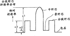
图7是本发明实施形态的,W+分段纤芯型折射率分布图;Fig. 7 is an embodiment of the present invention, a W+ segmented core-type refractive index distribution diagram;
图8A~图8C是本发明实施形态的,构成光传输线路的一个跨段的光纤组合例。8A to 8C are examples of combinations of optical fibers constituting one span of an optical transmission line according to an embodiment of the present invention.
具体实施形态Specific implementation form
第1实施形态1st embodiment
根据本发明人的考察,已有的光传输线路前级采用SMF而后级采用RDF的(SMF+RDF)型光传输线路,其传输损耗在1.55μm波段存在0.215dB/km的极限。其原因是,根据本发明人的考察可知,尽管正色散光纤(SMF)的传输损耗减小到0.19~0.20dB/km的程度,负色散光纤(RDF)的传输损耗在1.55μm波段大到0.24dB/km以上。这导致传输损耗造成的可传输距离缩短和输入功率增大造成的非线性现象。存在使前级正色散光纤(SMF)损耗进一步减小的手段,但射入负色散光纤(RDF)的入射功率会更强,因而不太理想。在这一意义上,希望正色散光纤与负色散光纤的传输损耗差小,不希望像已有的色散管理线路那样,传输损耗差在0.05dB/km以上。According to the investigation of the present inventors, the (SMF+RDF) type optical transmission line of the existing optical transmission line adopts SMF in the front stage and RDF in the rear stage, and its transmission loss has a limit of 0.215dB/km in the 1.55μm band. The reason is that, according to the investigation of the present inventor, although the transmission loss of the positive dispersion fiber (SMF) is reduced to the degree of 0.19~0.20dB/km, the transmission loss of the negative dispersion fiber (RDF) is as large as 0.24 in the 1.55 μm band. dB/km or more. This results in a reduction in the transmittable distance due to transmission loss and a non-linear phenomenon due to an increase in input power. There are means to further reduce the loss of the pre-stage positive dispersion fiber (SMF), but the incident power into the negative dispersion fiber (RDF) will be stronger, so it is not ideal. In this sense, it is hoped that the transmission loss difference between the positive dispersion fiber and the negative dispersion fiber is small, and it is not expected that the transmission loss difference is more than 0.05dB/km like the existing dispersion management lines.
因此,作为本发明的第1实施形态,本发明人完成了一种传输线路,其中不仅正色散光纤,而且负色散光纤均为0.23dB/km以下,两者的损耗差小于0.05dB/km(0.04dB/km以下较佳)。Therefore, as the first embodiment of the present invention, the present inventor has completed a kind of transmission line, wherein not only the positive dispersion optical fiber, but also the negative dispersion optical fiber is below 0.23dB/km, the loss difference of both is less than 0.05dB/km ( 0.04dB/km or less is better).
如图1所示,连接正色散光纤11和负色散光纤12,构成传输线路1,并且设传输线路1的总传输损耗取一定值,观察传输线路1中位于前段的正色散光纤11与位于后段的负色散光纤12的传输损耗差扩大时的非线性效应所造成的波形失真的程度。比较对象为传输损耗0.215dB/km、有效纤芯截面积Aeff为50μm2的NZ-DSF类光传输线路,并且将其光传输线路中产生的非线性现象造成的波形失真归一化。在该条件下,观察构成传输线路1的正色散光纤11和负色散光纤12的传输损耗差扩大时波形失真的情况。As shown in Figure 1, the positive dispersion
其条件假设为前段正色散光纤11的Aeff是90μm2,后段负色散光纤12的Aeff是30μm2,传输线路1的总传输损耗是0.215dB/km,并且将一个跨段的长度取为50km,即正色散光纤11的长度为25km,负色散光纤12的长度为25km。The conditions assume that the A eff of the
从图2可知,显然从传输损耗差为0.05dB/km左右开始,非线性现象变得显著起来。由此可知前段正色散光纤11与后段负色散光纤12两者的传输损耗差小于0.05dB/km较理想。It can be seen from Fig. 2 that the non-linear phenomenon becomes obvious when the transmission loss difference is about 0.05dB/km. It can be seen that it is ideal that the transmission loss difference between the
0.04dB/km以下的传输损耗的情况下则线性更好。因此,传输损耗最好在0.04dB/km以下。In the case of a transmission loss of 0.04dB/km or less, the linearity is better. Therefore, the transmission loss is preferably below 0.04dB/km.
第2实施形态Second Embodiment
根据本发明人的考察,已有的RDF通常具有弯曲损耗造成长波长侧的损耗增加的趋势,即1580nm的传输损耗有远高于1550nm的传输损耗的倾向。这成了严重问题,即C波段传输时也难调整波长损耗差别,而采用L波段时长波长侧的损耗增大。According to the research of the present inventors, the existing RDF generally has a tendency to increase the loss on the long wavelength side due to bending loss, that is, the transmission loss at 1580 nm tends to be much higher than the transmission loss at 1550 nm. This has become a serious problem, that is, it is difficult to adjust the wavelength loss difference in C-band transmission, and the loss on the long-wavelength side increases in L-band.
因此,本发明的第2实施形态,构成即便在1580nm也使正色散光纤11、负色散光纤12的传输损耗均为0.23dB/km以下的传输线路1。基本上将负色散光纤12的弯曲损耗抑制于较小的值,从而可抑制长波长侧的损耗增大,能够提供弯曲损耗小的负色散光纤12。Therefore, the second embodiment of the present invention constitutes the
第3实施形态3rd embodiment
作为本发明的第3实施形态,构成具有在1.55μm波段比已有SMF和RDF更加能够抑制色散值的类型的光纤的光纤传输线路。但是,为了完全抑制产生FWM的问题,将色散绝对值取为10ps/nm/km以上。这样,能缓解(SMF+RDF)类传输线路具有的那种大累积色散(large cumulative chromatic dispersion)的问题。而且,能减小负色散光纤的色散绝对值,通常意味着增加折射率分布的设计自由度(即使包层与纤芯之间的相对折射率差Δ1较小也能实现),从而便于将传输损耗抑制于较小的值。更进一步的优点是,与相对折射率差Δ1关系密切的极化模色散PMD也能够抑制于较小的值。As a third embodiment of the present invention, an optical fiber transmission line having a type of optical fiber capable of suppressing the dispersion value in the 1.55 μm band more than conventional SMF and RDF is constructed. However, in order to completely suppress the occurrence of the problem of FWM, the absolute value of the dispersion is set to be 10 ps/nm/km or more. In this way, the problem of large cumulative chromatic dispersion (SMF+RDF) type transmission lines can be alleviated. Moreover, being able to reduce the absolute value of the dispersion of the negative dispersion fiber usually means increasing the degree of freedom in the design of the refractive index distribution (even if the relative refractive index difference Δ1 between the cladding and the core is small), so that the transmission The loss is suppressed to a small value. A further advantage is that the polarization mode dispersion PMD, which is closely related to the relative refractive index difference Δ1, can also be suppressed to a small value.
图3示出对负色散光纤的色散(横轴)与传输损耗(曲线CV1)以及极化模色散PMD(曲线CV2)的关系进行调查的结果。由图3所示可知,减小色散对传输损耗和极化模色散PMD有利。因此,构成例如1.55μm波段中色散值为10~15ps/nm/km左右的正色散光纤和1.55μm波段中色散为-15~-10ps/nm/km左右的负色散光纤组合的传输线路。借助于此,不仅传输损耗,而且极化模色散PMD,都能抑制于例如
第4实施形态Fourth Embodiment
当然,即使优化负色散光纤12,在正色散光纤11的传输损耗大的情况下,也不能将传输线路的总传输损耗抑制为较小的值。因此,作为本发明的第4实施形态,正色散光纤11的传输损耗不仅小于0.23dB/km,而且最好小于以往已取得实效的0.20(最好0.195)dB/km以下。负色散光纤12的传输损耗,利用优化设计也弄清楚最好是0.225dB/km以下。在正色散光纤11的色散设定为14ps/nm/km,传输损耗设定为0.19dB/km,负色散光纤12的色散设定为-14ps/nm/km,传输损耗设定为0.22dB/km的情况下,一个跨段的长度取为50km,即正色散光纤11的长度为25km,负色散光纤12的长度为25km时,传输线路1的总传输损耗为0.205dB/km左右,是损耗非常低的特性。而且,这样构成的传输线路,其累积色散也比(SMF+RDF)类传输线路得到进一步抑制。Of course, even if the
第5实施形态Fifth Embodiment
正色散光纤11通常具有正色散斜率,因而希望使负色散光纤12具有负色散斜率。正色散光纤11的色散斜率几乎在各种情况下均为0.06~0.08ps/nm2/km,因而如果负色散光纤12的色散斜率为-0.02ps/nm2/km以下(最好为-0.03ps/nm2/km以下),则由正色散光纤11和负色散光纤12组合的本发明第5实施形态的光传输线路1,能达到已有的(NZ-DSF)类传输线路难以达到的0.03ps/nm2/km以下的低色散斜率。如图1的图解所示,正色散光纤11和负色散光纤12组合构成光传输线路1,从这样减小色散斜率的角度看也是有利的。
第6实施形态Embodiment 6
传输损耗和色散斜率小对传输线路非常重要,但如果有效纤芯截面积小,则有发生非线性现象的问题。因此希望入射较强功率的前段的正色散光纤11的Aeff为80μm2以上(最好是90μm2以上),入射较弱功率的后段的负色散光纤12的Aeff为30μm2以上。但是已经了解到,后段光纤12中需要其Aeff为不由于弯曲损耗造成长波长侧传输损耗增加的程度的Aeff,而且,如果考虑使用喇曼放大器的可能性,则Aeff为30μm2~34μm2左右较佳。当然,在不引起传输损耗增加的情况下,可根据情况进一步扩大Aeff。Small transmission loss and dispersion slope are very important for transmission lines, but if the effective core cross-sectional area is small, there is a problem that nonlinear phenomena will occur. Therefore, it is desirable that the A eff of the
为了调查长波长侧的损耗增加特性,研究了已有的型号的RDF的弯曲损耗与传输损耗的关系。图4表示其结果。In order to investigate the loss increase characteristics on the long-wavelength side, the relationship between the bending loss and the transmission loss of a conventional RDF was studied. Fig. 4 shows the results.
弯曲损耗是指以某一曲率直径(图4的例子中,曲率直径为φ20mm)弯曲光传输线路时在某一波长的传输损耗的增加。Bending loss refers to an increase in transmission loss at a certain wavelength when an optical transmission line is bent with a certain curvature diameter (in the example of FIG. 4, the curvature diameter is φ20 mm).
从图4所示可知,已有的型号的RDF中,由于加大弯曲损耗,可扩大虚线所示的Aeff(曲线CV3),但实线所示的长波长侧的传输损耗(曲线CV4)增加。为了将1580nm和1550nm的传输损耗差抑制于0.05dB/km以下,显然需要将φ20mm的弯曲损耗至少抑制于10dB/m以下(最好是8dB/m以下)。As can be seen from Fig. 4, in the conventional RDF model, by increasing the bending loss, the A eff shown by the dotted line (curve CV3) can be enlarged, but the transmission loss on the long wavelength side shown by the solid line (curve CV4) Increase. In order to suppress the transmission loss difference between 1580nm and 1550nm below 0.05dB/km, it is obviously necessary to suppress the bending loss of φ20mm below 10dB/m (preferably below 8dB/m).
为了实现如上所述的传输线路1,分别设计了正色散光纤11和负色散光纤12。结果判明在折射率分布对正色散光纤为图5所示的阶梯分布(profile)、图6所示的分段纤芯型分布和图7所示的(W+分段纤芯)型分布,以及对负色散光纤则为图7所示的(W+分段纤芯)型分布,分别能够取得上述那样的特性。In order to realize the
图5~图7中,中纤芯位于中央。In FIGS. 5 to 7 , the central fiber core is located in the center.
图5的阶梯型分布是指折射率大的中纤芯位于中间,并且在其外周形成比中纤芯折射率小而平坦的旁纤芯的折射率分布。旁纤芯的外周形成比旁纤芯折射率小的包层。The stepped distribution in FIG. 5 refers to a refractive index distribution in which the central core with a large refractive index is located in the middle, and a side core with a lower and flatter refractive index than the central core is formed on its outer periphery. A cladding having a lower refractive index than that of the side core is formed on the periphery of the side core.
第7实施形态Seventh Embodiment
作为典型正色散光纤的已有型号的SMF具有由中心的纤芯和设置在其周边的包层构成的简单的2层结构。这种SMF由于纤芯的折射率与包层的折射率之间的相对折射率差Δ1低达0.4%,Aeff大,传输损耗也达到0.195dB/km以下。然而,这种SMF通常在1.55μm波段的色散值为16ps/nm/km以上,在色散值大的方面存在问题。The conventional SMF, which is a typical positive dispersion fiber, has a simple two-layer structure consisting of a core at the center and a cladding provided around the core. Due to the relative refractive index difference Δ1 between the refractive index of the core and the refractive index of the cladding of this SMF is as low as 0.4%, the Aeff is large, and the transmission loss is also below 0.195dB/km. However, such an SMF generally has a dispersion value of 16 ps/nm/km or more in the 1.55 μm band, and has a problem in that the dispersion value is large.
纤芯折射率与包层折射率之间的相对折射率差Δ1按下式定义。The relative refractive index difference Δ1 between the core refractive index and the cladding refractive index is defined as follows.
其中,n1为纤芯的折射率,n0为包层折射率。Among them, n 1 is the refractive index of the fiber core, and n 0 is the cladding refractive index.
这里,首先用3层结构研究色散抑制。如果减小中纤芯的折射率,则对弯曲损耗的敏感性(影响)增大,从而引起长波长侧的传输损耗增加,而如果加大中纤芯的折射率,不仅传输损耗增大到0.20dB/km以上,而且Aeff小于80μm2,所以使相对折射率差Δ1维持在约0.4%(例如0.35~0.45%)。Here, dispersion suppression is first studied with a 3-layer structure. If the refractive index of the middle fiber core is reduced, the sensitivity (influence) to the bending loss increases, which causes the transmission loss on the long wavelength side to increase, and if the refractive index of the middle fiber core is increased, not only the transmission loss increases to 0.20 dB/km or more, and A eff is less than 80 μm 2 , so the relative refractive index difference Δ1 is maintained at about 0.4% (for example, 0.35 to 0.45%).
该条件下,如图5所示,在增添包层折射率与旁纤芯折射率之间的相对折射率差Δ2为0.05~0.25%,且旁纤芯直径b与中纤芯直径a比、即倍率(b/a)为1.8~2.7倍的旁纤芯层时,有可能得到所希望的色散。模拟的结果获得良好的特性。表1表示光纤的应该例子。Under this condition, as shown in Figure 5, the relative refractive index difference Δ2 between the refractive index of the added cladding and the refractive index of the side core is 0.05% to 0.25%, and the ratio of the side core diameter b to the middle core diameter a, That is, when the magnification (b/a) is 1.8 to 2.7 times the side core layer, it is possible to obtain the desired dispersion. As a result of the simulation, good characteristics were obtained. Table 1 shows examples of optical fibers.
包层与旁纤芯的相对折射率差Δ2按下式定义。The relative refractive index difference Δ2 between the cladding and the side core is defined by the following formula.
其中,n0为包层折射率,n2为旁纤芯折射率。Among them, n 0 is the refractive index of the cladding, and n 2 is the refractive index of the side core.
表1 正色散光纤模拟结果(3层结构)Table 1 Simulation results of positive dispersion fiber (3-layer structure)
表1中,Δ1表示纤芯折射率与包层折射率之间的相对折射率差,α为表示中纤芯折射率分布形状的参数,b/a表示旁纤芯直径b相对于中纤芯直径a的倍率,色散表示色散值,slope表示色散斜率,Aeff表示有效纤芯截面积,λc表示截止波长,弯曲φ20表示φ20mm的弯曲损耗。In Table 1, Δ1 represents the relative refractive index difference between the core refractive index and the cladding refractive index, α is a parameter representing the shape of the mid-core refractive index distribution, b/a represents the diameter of the side core b relative to the mid-core The magnification of diameter a, dispersion means dispersion value, slope means dispersion slope, A eff means effective core cross-sectional area, λc means cut-off wavelength, bending φ20 means bending loss of φ20mm.
在色散特性、Aeff、弯曲损耗特性方面取得良好特性。而且,相对折射率差Δ1为0.4%左右,因而可期望传输损耗为0.195dB/km以下。于是可知例如用这种阶梯型折射率分布(图5)能得到作为本发明目的的光纤传输线路1。Good characteristics were obtained in terms of dispersion characteristics, A eff , and bending loss characteristics. Furthermore, the relative refractive index difference Δ1 is about 0.4%, so the transmission loss can be expected to be 0.195 dB/km or less. Thus, it can be seen that, for example, the optical
第8实施形态Eighth embodiment
如上文所述那样将色散值抑制于15ps/nm/km以下,但以进一步抑制色散值为目标,探讨一下具有图6、图7所示4层以上的折射率分布的结构。与上文所述完全相同,取包层与中纤芯间的相对折射率差的值为0.4%左右,这时调整包层与旁纤芯的相对折射率差Δ2、包层与分段纤芯间的相对折射率差Δ3、直径比a∶b∶c的各参数,使Aeff、λc、色散值等为最佳值。可知为了满足色散值10~15ps/nm/km的条件,同时获得80μm2以上的大Aeff和1550nm以下的λc,需要使相对折射率差Δ2的值为-0.10~0.10%,相对折射率差Δ3的值为0.10~0.25%,b为1.3~1.9,c为2.2~2.8。模拟结果取得的特性良好的折射率分布示于表2。As mentioned above, the dispersion value is suppressed to 15 ps/nm/km or less, but with the aim of further suppressing the dispersion value, a structure having a refractive index distribution of four or more layers as shown in Fig. 6 and Fig. 7 will be considered. Exactly the same as above, take the value of the relative refractive index difference between the cladding and the middle core as about 0.4%. At this time, adjust the relative refractive index difference Δ2 between the cladding and the side core, and For the relative refractive index difference Δ3 between the cores and the parameters of the diameter ratio a:b:c, A eff , λc, dispersion value, etc. are optimized. It can be seen that in order to satisfy the condition of the dispersion value of 10-15 ps/nm/km and simultaneously obtain a large A eff above 80 μm 2 and a λc below 1550 nm, it is necessary to set the value of the relative refractive index difference Δ2 to -0.10 to 0.10%, and the relative refractive index difference The value of Δ3 is 0.10 to 0.25%, b is 1.3 to 1.9, and c is 2.2 to 2.8. Table 2 shows the characteristic refractive index distribution obtained as a result of the simulation.
包层与分段纤芯之间的相对折射率差Δ3按下式定义。The relative refractive index difference Δ3 between the cladding and the segmented core is defined as follows.
其中:n0为包层折射率,n3为分段纤芯折射率。Among them: n 0 is the cladding refractive index, n 3 is the segmented core refractive index.
表2 正色散光纤模拟结果(4层结构)Table 2 Simulation results of positive dispersion fiber (4-layer structure)
表2中,Δ1表示包层与上述中纤芯之间的相对折射率差,Δ2表示包层与旁纤芯的相对折射率差,Δ3表示包层与分段纤芯之间的相对折射率差,α为表示中纤芯折射率分布形状的参数,a∶b∶c表示中纤芯直径a、旁纤芯直径b和分段纤芯直径c之间的比例关系,色散表示色散值,slope表示色散斜率,Aeff表示有效纤芯截面积,λc表示截止波长,弯曲φ20表示φ20mm的弯曲损耗。In Table 2, Δ1 represents the relative refractive index difference between the cladding and the above-mentioned middle core, Δ2 represents the relative refractive index difference between the cladding and the adjacent core, and Δ3 represents the relative refractive index between the cladding and the segmented core difference, α is a parameter representing the shape of the central core refractive index distribution, a:b:c represents the proportional relationship between the central core diameter a, the side core diameter b and the segmented core diameter c, and the dispersion represents the dispersion value, slope represents the dispersion slope, A eff represents the effective core cross-sectional area, λc represents the cut-off wavelength, and bending φ20 represents the bending loss of φ20mm.
从该结果可知,显然用例如这样的分段纤芯型分布(图6)或(W+分段纤芯)型分布(图7)能获得特性良好的光纤传输线路。From this result, it is clear that, for example, such a segmented core type distribution (FIG. 6) or a (W+segmented core) type distribution (FIG. 7) can obtain an optical fiber transmission line with good characteristics.
第9实施形态Embodiment 9
还对负色散光纤进行优化。已有的RDF采用W型折射率分布,并且在未达到弯曲损耗极限的条件下,使相对折射率差Δ1减小,以此实现低损耗特性和小色散值。虽然也可以使相对折射率差Δ1减小得更多,以进一步减小损耗和色散绝对值,但弯曲损耗将变得非常大。但是,利用在W型折射率分布的外侧增添分段纤芯层的结构,可以抑制弯曲损耗。因此,采用图7所示的(W+分段纤芯)型分布(profile),研究在1.55μm满足-15~-10ps/nm/km色散值,并且在弯曲损耗非常小的范围(φ20mm为10dB/km以下)有可能将Aeff扩大到30μm2以上的分布。It is also optimized for negative dispersion fibers. The existing RDF adopts a W-shaped refractive index distribution, and under the condition that the bending loss limit is not reached, the relative refractive index difference Δ1 is reduced, so as to achieve low loss characteristics and small dispersion values. Although the relative refractive index difference Δ1 can also be reduced more to further reduce the absolute value of loss and dispersion, but the bending loss will become very large. However, bending loss can be suppressed by adding a segmented core layer to the outside of the W-shaped refractive index distribution. Therefore, using the (W+segmented core) type profile shown in Figure 7, the study satisfies the dispersion value of -15~-10ps/nm/km at 1.55μm, and in the range of very small bending loss (φ20mm is 10dB /km or less) it is possible to expand the A eff to a distribution above 30 μm 2 .
作为满足传输损耗小于0.23dB/km的包层与中纤芯间的相对折射率差Δ1,选择0.85%左右(例如0.8%~0.9%)。相对折射率差Δ1为0.80%以下时有可能因弯曲损耗增大造成长波长侧的传输损耗增加。还了解到,表示中纤芯折射率分布形状的参数α接近2.0(例如为1.5~3.0)能使色散斜率为-0.030ps/nm2/km以下的小数值。对各相对折射率差Δ1优化的旁纤芯结构的研究结果表明,包层与旁纤芯的相对折射率差Δ2为-0.45~-0.35%、包层与分段纤芯之间的相对折射率差Δ3为0.15~0.25%是最佳范围。还了解到,为了抑制长波长侧的损耗增加,相对折射率差Δ2需要在-0.45%以上,但至少在相对折射率差Δ2不在0.35%以下时,色散斜率增大到-0.03ps/nm2/km以上。而且,为了抑制长波长侧的传输损耗增加,相对折射率差Δ3需要在0.15%以上,但如果相对折射率差Δ3超过0.35%,则λc增大到1500nm以上,不能满足单模条件。As the relative refractive index difference Δ1 between the cladding layer and the core that satisfies the transmission loss of less than 0.23 dB/km, about 0.85% (for example, 0.8% to 0.9%) is selected. When the relative refractive index difference Δ1 is 0.80% or less, there is a possibility that the transmission loss on the long wavelength side increases due to an increase in bending loss. It is also known that the parameter α representing the shape of the central core refractive index distribution is close to 2.0 (for example, 1.5 to 3.0) so that the dispersion slope can be reduced to a small value below -0.030 ps/nm 2 /km. The research results of the side core structure optimized for each relative refractive index difference Δ1 show that the relative refractive index difference Δ2 between the cladding and the side core is -0.45~-0.35%, and the relative refraction between the cladding and the segmented core The rate difference Δ3 is 0.15-0.25% which is the optimum range. It is also known that in order to suppress the increase in loss on the long wavelength side, the relative refractive index difference Δ2 needs to be -0.45% or more, but at least when the relative refractive index difference Δ2 is not less than 0.35%, the dispersion slope increases to -0.03ps/nm 2 /km or more. In addition, in order to suppress the increase in transmission loss on the long wavelength side, the relative refractive index difference Δ3 needs to be 0.15% or more, but if the relative refractive index difference Δ3 exceeds 0.35%, λc increases to 1500nm or more, and the single-mode condition cannot be satisfied.
又调整中纤芯直径a、旁纤芯直径b和分段纤芯直径c之间的比率a∶b∶c的值。a∶b的比率为1∶(1.7~2.0)时,使其他特性维持良好的值,同时取得低弯曲损耗特性,了解到如果小于1.7,则色散特性差,大于2.0,则λc大到1500nm以上。而且,a∶b的比率为1∶23~1∶3.0时色散斜率如果在-0.03ps/nm2/km以下,则维持高补偿率不变,弯曲损耗也在10dB/m(φ20mm)以下,不受损,而且截止波长λc保持在1500nm以下。因此,直径比(a∶b∶c)选择为1∶(1.7~2.0)∶(2.3~3.0)。In addition, the value of the ratio a:b:c between the central core diameter a, side core diameter b and segment core diameter c is adjusted. When the ratio of a:b is 1:(1.7 to 2.0), other characteristics are maintained at good values while low bending loss characteristics are obtained. If it is less than 1.7, the dispersion characteristics are poor, and if it is greater than 2.0, λc is as large as 1500nm or more. . Moreover, when the ratio of a:b is 1:23 to 1:3.0, if the dispersion slope is below -0.03ps/nm 2 /km, the high compensation rate remains unchanged, and the bending loss is also below 10dB/m (φ20mm), It is not damaged, and the cut-off wavelength λc remains below 1500nm. Therefore, the diameter ratio (a:b:c) is selected as 1:(1.7-2.0):(2.3-3.0).
下面示出从模拟结果得到的,将损失维持于较小的值,同时能实现良好的特性的分布的例子。The following shows examples of distributions obtained from simulation results that can achieve good characteristics while maintaining the loss at a small value.
表3中,Δ1表示包层与中纤芯之间的相对折射率差,Δ2表示包层与旁纤芯的相对折射率差,Δ3表示包层与分段纤芯之间的相对折射率差,α为表示中纤芯折射率分布形状的参数,a∶b∶c表示中纤芯直径a、旁纤芯直径b和分段纤芯直径c之间的比例关系,色散表示色散值,slope表示色散斜率,Aeff表示有效纤芯截面积,λc表示截止波长,弯曲φ20表示φ20mm的弯曲损耗。In Table 3, Δ1 represents the relative refractive index difference between the cladding and the middle core, Δ2 represents the relative refractive index difference between the cladding and the adjacent core, and Δ3 represents the relative refractive index difference between the cladding and the segmented core , α is a parameter representing the shape of the central core refractive index distribution, a:b:c represents the proportional relationship between the central core diameter a, the side core diameter b and the segmented core diameter c, the dispersion represents the dispersion value, slope Represents the dispersion slope, A eff represents the effective core cross-sectional area, λc represents the cut-off wavelength, and bending φ20 represents the bending loss of φ20mm.
表3 负色散光纤模拟结果(1)Table 3 Simulation results of negative dispersion fiber (1)
第10实施形态Tenth Embodiment
对于负色散光纤也进行是否可进一步抑制色散的研究。为了抑制色散值,包层与分段纤芯之间的相对折射率差Δ1降到0.70%左右(例如0.65%~0.75%)是有效的。然而,如上文所述,相对折射率Δ1小会导致长度波长侧的传输损耗增加。为了抑制该长波长侧的传输损耗增加,将表示中纤芯折射率分布形状的参数α取为10左右。这样,色散斜率比表3的负色散光纤有若干增大,但可以看出利用使分布(profile)优化的方法可获得-0.020ps/nm2/km以下的色散斜率值。还可以看出,为了维持小色散值同时将弯曲损耗抑制于10dB/m(φ20mm)以下,包层与旁纤芯的相对折射率差Δ2需要在-0.50%以上,但至少在相对折射率差Δ2不为-0.40%以下时,色散斜率大于0.02ps/nm2/km。为了抑制长波长侧的传输损耗增加,包层与分段纤芯之间的相对折射率差Δ3需要在0.15%以上,但相对折射率差Δ3如果超过0.25%,则截止波长λc向长波长侧移动,不满足单模条件。Whether the dispersion can be further suppressed is also studied for the negative dispersion fiber. In order to suppress the dispersion value, it is effective to reduce the relative refractive index difference Δ1 between the cladding layer and the segmented core to about 0.70% (for example, 0.65% to 0.75%). However, as described above, a small relative refractive index Δ1 leads to an increase in transmission loss on the length wavelength side. In order to suppress the increase in the transmission loss on the long wavelength side, the parameter α indicating the shape of the mid-core refractive index distribution is set to about 10. Thus, the dispersion slope is somewhat larger than that of the negative dispersion fiber in Table 3, but it can be seen that the dispersion slope value below -0.020 ps/nm 2 /km can be obtained by optimizing the profile. It can also be seen that in order to maintain a small dispersion value while suppressing the bending loss below 10dB/m (φ20mm), the relative refractive index difference Δ2 between the cladding and the adjacent core needs to be above -0.50%, but at least the relative refractive index difference When Δ2 is not less than -0.40%, the dispersion slope exceeds 0.02 ps/nm 2 /km. In order to suppress the increase in transmission loss on the long wavelength side, the relative refractive index difference Δ3 between the cladding and the segmented core needs to be 0.15% or more, but if the relative refractive index difference Δ3 exceeds 0.25%, the cutoff wavelength λc is toward the long wavelength side Mobile, does not meet the single-mode condition.
又调整a∶b∶c的值。a∶b的值为1∶1.8~1∶2.2时,使其他特性维持良好的值,同时取得在φ20mm情况下为10dB/m以下的低弯曲损耗特性。1.8以下时色散绝对值变大,2.2以上时截止波长λc从1500nm向长波长侧移动。又,将a∶c的值取为1∶2.7~1∶3.0。这是因为在2.7以上维持高补偿率不变,使弯曲损耗也在10dB/m以下(φ20mm),不受损,而在3.0以下截止波长λc保持于1500nm以下。因此,直径比(a∶b∶c)选择为1∶(1.8~2.2)∶(2.7~3.0)。Also adjust the value of a:b:c. When the value of a:b is 1:1.8 to 1:2.2, low bending loss characteristics of 10 dB/m or less in the case of φ20 mm are obtained while maintaining other characteristics at good values. When it is 1.8 or less, the absolute value of dispersion increases, and when it is 2.2 or more, the cutoff wavelength λc shifts from 1500 nm to the long wavelength side. Also, the value of a:c is set to be 1:2.7 to 1:3.0. This is because the high compensation rate is maintained above 2.7, so that the bending loss is also below 10dB/m (φ20mm), without damage, and the cut-off wavelength λc is kept below 1500nm below 3.0. Therefore, the diameter ratio (a:b:c) is selected as 1:(1.8-2.2):(2.7-3.0).
模拟的结果,使损耗维持小的值,同时能实现良好的特性的分布的例子如下所示。As a result of the simulation, an example of the distribution that can achieve good characteristics while maintaining the loss at a small value is shown below.
表4负 色散光纤模拟结果(2)Table 4 negative dispersion fiber simulation results (2)
从以上的结果可知,将当前发明的图1所示的正色散光纤11的和负色散光纤12加以连接,构成光传输线路1,就能够得到可实现低非线性、低弯曲损耗特性和低色散斜率这样的结果。而且光传输线路1具有已有的RDF与NZ-DSF之间的色散值,从而能抑制累积色散。再者,从折射率分布形状方面看来,光传输线路1在较宽的频带实现了低损耗特性和极化模色散PMD特性。From the above results, it can be known that the positive dispersion
如上所述,开发将新型正色散光纤和负色散光纤加以组合的传输线路,在较宽频带实现低损耗特性的同时,也实现累积色散小、非线性低、色散斜率小、极化模色散PMD小的特性。该新传输线路的低损耗、小累积色散、低极化模色散PMD、小色散斜率和低非线性的特性最适合作为高速WDM传输线路。采用这种正色散光纤和负色散光纤构成的新型传输线路是将来能成为WDM传输的胜利者的传输线路,以此能方便地制作适合高速大容量传输的传输线路。As mentioned above, the development of a transmission line that combines a new type of positive dispersion fiber and negative dispersion fiber achieves low loss characteristics over a wide frequency band, and at the same time realizes small cumulative dispersion, low nonlinearity, small dispersion slope, and polarization mode dispersion (PMD). small features. The characteristics of low loss, small cumulative dispersion, low polarization mode dispersion PMD, small dispersion slope and low nonlinearity of the new transmission line are most suitable as high-speed WDM transmission lines. The new type of transmission line composed of positive dispersion fiber and negative dispersion fiber is the transmission line that will become the winner of WDM transmission in the future, so that it can conveniently manufacture transmission lines suitable for high-speed and large-capacity transmission.
实施例Example
下面,利用实施例确认本发明的实施形态的光纤的有效性。Next, the effectiveness of the optical fiber according to the embodiment of the present invention will be confirmed using examples.
实施例1Example 1
首先,进行试制以获得具有图5中说明的阶梯型分布的正色散光纤。表5示出参考模拟结果进行试制的结果。First, a trial production was carried out to obtain a positive dispersion fiber having the step profile illustrated in FIG. 5 . Table 5 shows the results of trial production with reference to the simulation results.
表5正色散光纤试制结果(3层结构)Table 5 Trial production results of positive dispersion fiber (3-layer structure)

由于包层与分段纤芯之间的相对折射率差Δ1较小,在1.55μm和1.58μm的传输损耗也低达0.19dB/km左右。而且,试制件1、2均有效截面积Aeff90μm2以上,取得大于已有的SMF的Aeff值。而且1.55μm波段的色散值比SMF得到进一步抑制。试制件1、2的色散值与已有型的NZ-DSF相比,该值足够大,因而能期望抑制FWM造成的信号噪声。截止波长λc虽然略大,但在采用22m长的光纤测量截止波长λc的“22m法”的测量中得到该截止波长小于1400nm。色散斜率、弯曲损耗、极化模色散PMD等其他特性也良好。Since the relative refractive index difference Δ1 between the cladding layer and the segmented core is small, the transmission loss at 1.55 μm and 1.58 μm is also as low as about 0.19 dB/km. In addition, the effective cross-sectional area A eff of prototypes 1 and 2 is 90 μm 2 or more, and the A eff value is larger than that of the existing SMF. Moreover, the dispersion value in the 1.55μm band is further suppressed than that of SMF. The dispersion values of the
实施例2Example 2
关于4层结构的分布,也参考模拟结果进行若干试制。表6示出试制结果。Regarding the distribution of the four-layer structure, some trial productions were also performed with reference to the simulation results. Table 6 shows the trial production results.
表6 正色散光纤试制结果(4层结构)Table 6 Trial production results of positive dispersion fiber (4-layer structure)

从表6可知,在采用4层结构的情况下,依旧维持低损耗不变,能够将色散值进一步抑制于11~13ps/nm/km左右。与表5的试制结果相比,有效截面积Aeff有若干减小,但是能够进一步抑制累积色散。弯曲损耗的值比表5的值略大,但能抑制于10dB/m以下,1.58μm的损耗也达到0.200dB/km左右的不成问题的程度。It can be seen from Table 6 that in the case of adopting a 4-layer structure, the low loss is still maintained, and the dispersion value can be further suppressed to about 11-13 ps/nm/km. Compared with the trial production results in Table 5, the effective cross-sectional area A eff was slightly reduced, but the cumulative dispersion could be further suppressed. The value of the bending loss is slightly larger than the value in Table 5, but it can be suppressed below 10 dB/m, and the loss of 1.58 μm is also about 0.200 dB/km, which is not a problem.
实施例3Example 3
还用(W+分段纤芯)型分布进行试制,以图获得负色散光纤。表7示出根据模拟进行试制的结果。Trial production was also carried out with (W+segmented fiber core) type distribution in order to obtain negative dispersion fiber. Table 7 shows the results of trial production based on simulation.
表7 负色散光纤试制结果Table 7 Trial production results of negative dispersion fiber

根据表7的结果,不仅获得0.215dB/km左右的低传输损耗,而且获得有效截面积Aeff、色散补偿率、极化模色散PMD等非常良好的结果。而且弯曲损耗也抑制于较小的程度,1.58μm的传输损耗在0.23dB/km以下,可确认有稳定的特性。According to the results in Table 7, not only a low transmission loss of about 0.215dB/km is obtained, but also very good results such as effective cross-sectional area A eff , dispersion compensation rate, and polarization mode dispersion PMD are obtained. In addition, the bending loss is also suppressed to a small degree, and the transmission loss at 1.58 μm is below 0.23 dB/km, and stable characteristics can be confirmed.
本发明的光传输线路的形态如图1、图8A所示,可以把多个由正色散光纤11和负色散光纤12连接构成跨段(单元)的光传连接成所需的距离的光传输线路1。The form of the optical transmission line of the present invention is shown in Fig. 1 and Fig. 8A, and a plurality of positive dispersion
一个跨段的结构,不仅是用图1说明的正色散光纤11和负色散光纤12的组合,而且可以有各种形态。The structure of a span is not only the combination of the
例如,为了适应双向通信,也可如图8B说明的那样,构成用正色散光纤+负色散光纤+正色散光纤组成一个跨段的光传输线路。For example, in order to adapt to two-way communication, as illustrated in FIG. 8B , a span of optical transmission lines composed of positive dispersion fiber + negative dispersion fiber + positive dispersion fiber can also be formed.
又例如,为了抑制累积色散的增加,也可如图8C说明的那样,构成用4根以上光纤组成一个跨段这种类型的光纤。As another example, in order to suppress an increase in cumulative dispersion, it is also possible to configure an optical fiber of the type in which one span is composed of four or more optical fibers as described in FIG. 8C.
组成一个跨段的光纤种类及其组合可按照目的或根据状况决定。The types of optical fibers constituting a span and combinations thereof may be determined according to purpose or according to circumstances.
本实施形态的任一传输线路中,都能根据上述损耗特性取得有利特性。In any transmission line of this embodiment, advantageous characteristics can be obtained from the above-mentioned loss characteristics.
如上所述,采用本发明,在将正色散光纤和负色散光纤加以连接时,可在宽大的波长范围内获得低损耗和小色散。As described above, with the present invention, when the positive dispersion fiber and the negative dispersion fiber are connected, low loss and small dispersion can be obtained over a wide wavelength range.
又,采用本发明,能够实现非线性低。Also, according to the present invention, low nonlinearity can be achieved.
还有,极化模色散PMD和任一种光纤都呈现低于
采用本发明,能够构成兼有对SPM、XPM、FWM等的低非线性和色散平坦性的、适合高速大容量传输的低损耗WDM传输线路。By adopting the present invention, a low-loss WDM transmission line suitable for high-speed and large-capacity transmission can be constructed, which has both low nonlinearity and dispersion flatness for SPM, XPM, FWM and the like.
Claims (15)
Applications Claiming Priority (6)
| Application Number | Priority Date | Filing Date | Title |
|---|---|---|---|
| JP2001226054 | 2001-07-26 | ||
| JP2001-226054 | 2001-07-26 | ||
| JP2001226054 | 2001-07-26 | ||
| JP2002-122826 | 2002-04-24 | ||
| JP2002122826A JP3869305B2 (en) | 2001-07-26 | 2002-04-24 | Optical transmission line |
| JP2002122826 | 2002-04-24 |
Publications (2)
| Publication Number | Publication Date |
|---|---|
| CN1400764A CN1400764A (en) | 2003-03-05 |
| CN100435503C true CN100435503C (en) | 2008-11-19 |
Family
ID=26619322
Family Applications (1)
| Application Number | Title | Priority Date | Filing Date |
|---|---|---|---|
| CNB021273863A Expired - Fee Related CN100435503C (en) | 2001-07-26 | 2002-07-23 | optical transmission line |
Country Status (5)
| Country | Link |
|---|---|
| US (1) | US6701051B2 (en) |
| EP (1) | EP1279977A2 (en) |
| JP (1) | JP3869305B2 (en) |
| CN (1) | CN100435503C (en) |
| CA (1) | CA2391187A1 (en) |
Families Citing this family (8)
| Publication number | Priority date | Publication date | Assignee | Title |
|---|---|---|---|---|
| EP1116970A1 (en) * | 1999-06-28 | 2001-07-18 | The Furukawa Electric Co., Ltd. | Optical transmission line |
| JP4123823B2 (en) * | 2002-05-17 | 2008-07-23 | 住友電気工業株式会社 | Dispersion compensation unit and optical communication system |
| US20040234275A1 (en) * | 2003-05-20 | 2004-11-25 | Aref Chowdhury | Process for optical communication and system for same |
| US7024083B2 (en) * | 2004-02-20 | 2006-04-04 | Corning Incorporated | Non-zero dispersion shifted optical fiber |
| KR100759805B1 (en) * | 2005-12-07 | 2007-09-20 | 한국전자통신연구원 | Optically boosted elctroabsorption duplexer |
| JP4974161B2 (en) * | 2007-07-27 | 2012-07-11 | 古河電気工業株式会社 | Optical fiber device |
| JP5619516B2 (en) | 2010-08-04 | 2014-11-05 | 古河電気工業株式会社 | Optical fiber |
| CN112346174B (en) | 2019-08-09 | 2022-12-02 | 华为技术有限公司 | A polymer waveguide and terahertz signal transmission method |
Citations (2)
| Publication number | Priority date | Publication date | Assignee | Title |
|---|---|---|---|---|
| JPH09211511A (en) * | 1996-02-05 | 1997-08-15 | Furukawa Electric Co Ltd:The | Optical communication system |
| CA2232101A1 (en) * | 1997-03-25 | 1998-09-25 | Kazunori Mukasa | Dispersion compensating optical fiber, and wavelength division multiplex light transmission line using the same |
Family Cites Families (2)
| Publication number | Priority date | Publication date | Assignee | Title |
|---|---|---|---|---|
| WO2001063327A1 (en) * | 2000-02-24 | 2001-08-30 | Sumitomo Electric Industries, Ltd. | Optical transmission line and optical transmission system including it |
| JP4531954B2 (en) | 2000-09-01 | 2010-08-25 | 古河電気工業株式会社 | Optical fiber and optical transmission line using the optical fiber |
-
2002
- 2002-04-24 JP JP2002122826A patent/JP3869305B2/en not_active Expired - Fee Related
- 2002-06-20 CA CA002391187A patent/CA2391187A1/en not_active Abandoned
- 2002-07-01 US US10/184,802 patent/US6701051B2/en not_active Expired - Lifetime
- 2002-07-19 EP EP02255092A patent/EP1279977A2/en not_active Withdrawn
- 2002-07-23 CN CNB021273863A patent/CN100435503C/en not_active Expired - Fee Related
Patent Citations (2)
| Publication number | Priority date | Publication date | Assignee | Title |
|---|---|---|---|---|
| JPH09211511A (en) * | 1996-02-05 | 1997-08-15 | Furukawa Electric Co Ltd:The | Optical communication system |
| CA2232101A1 (en) * | 1997-03-25 | 1998-09-25 | Kazunori Mukasa | Dispersion compensating optical fiber, and wavelength division multiplex light transmission line using the same |
Non-Patent Citations (1)
| Title |
|---|
| "Novel Network Fiber to Manage Dispersion at 1.55 mumwith Combination of 1.3 mum Zero Dispersion Single ModeFiber". Kazunori,Mukasa,et,al.11th International Conference on Integrated Optics and Optical Fibre Communications, 23rd European Conference on Optical Communications,第1卷. 1997 * |
Also Published As
| Publication number | Publication date |
|---|---|
| CA2391187A1 (en) | 2003-01-26 |
| CN1400764A (en) | 2003-03-05 |
| US20030063877A1 (en) | 2003-04-03 |
| EP1279977A2 (en) | 2003-01-29 |
| JP3869305B2 (en) | 2007-01-17 |
| JP2003107258A (en) | 2003-04-09 |
| US6701051B2 (en) | 2004-03-02 |
Similar Documents
| Publication | Publication Date | Title |
|---|---|---|
| JP4494691B2 (en) | Optical transmission line | |
| JPWO2001001179A1 (en) | Optical transmission line | |
| US6640036B2 (en) | Optical fiber and optical communication system using this optical fiber | |
| EP1124145A1 (en) | Optical fiber and optical transmission line including the same | |
| US6684018B2 (en) | Low-dispersion optical fiber and optical transmission system using the low-dispersion optical fiber | |
| JPWO2000017685A1 (en) | Dispersion Compensating Fiber | |
| JP4443788B2 (en) | Optical fiber and optical communication system using the optical fiber | |
| JP4531954B2 (en) | Optical fiber and optical transmission line using the optical fiber | |
| JP2002341157A (en) | Wavelength multiplexing transmission line and dispersion compensating optical fiber used for the same | |
| CN100435503C (en) | optical transmission line | |
| US6983094B2 (en) | Optical fiber and optical transmission system using such optical fiber | |
| JPH1184159A (en) | Dispersion flat fiber | |
| JP2006293117A (en) | Optical fiber and optical communication system using the same | |
| JP4413456B2 (en) | Negative dispersion optical fiber and optical transmission line using the negative dispersion optical fiber | |
| JP3808290B2 (en) | Dispersion-shifted optical fiber | |
| JP4079104B2 (en) | Dispersion compensating optical fiber, dispersion compensator and optical transmission line | |
| JP2003188822A (en) | Optical transmission line and optical transmission system using the optical transmission line | |
| US6707971B2 (en) | Dispersion management optical transmission system and optical transmission line | |
| JP2000275461A (en) | Dispersion shifted optical fiber | |
| JP2005003794A (en) | Optical fiber and optical transmission line using the same | |
| JP4028409B2 (en) | Wavelength division multiplexing optical fiber | |
| JP2004021075A (en) | Dispersion compensating optical fiber and optical transmission line using the same | |
| JP2003298520A (en) | Dispersion management optical transmission system and optical transmission path | |
| JP2001324636A (en) | Dispersion shifted optical fiber | |
| JP2007293351A (en) | Low dispersion optical fiber and optical transmission system using the low dispersion optical fiber |
Legal Events
| Date | Code | Title | Description |
|---|---|---|---|
| C06 | Publication | ||
| PB01 | Publication | ||
| C10 | Entry into substantive examination | ||
| SE01 | Entry into force of request for substantive examination | ||
| C14 | Grant of patent or utility model | ||
| GR01 | Patent grant | ||
| CF01 | Termination of patent right due to non-payment of annual fee | ||
| CF01 | Termination of patent right due to non-payment of annual fee |
Granted publication date: 20081119 Termination date: 20180723 |