CN100470433C - servo controller - Google Patents
servo controller Download PDFInfo
- Publication number
- CN100470433C CN100470433C CNB038260425A CN03826042A CN100470433C CN 100470433 C CN100470433 C CN 100470433C CN B038260425 A CNB038260425 A CN B038260425A CN 03826042 A CN03826042 A CN 03826042A CN 100470433 C CN100470433 C CN 100470433C
- Authority
- CN
- China
- Prior art keywords
- speed
- axis
- model
- command
- control unit
- Prior art date
- Legal status (The legal status is an assumption and is not a legal conclusion. Google has not performed a legal analysis and makes no representation as to the accuracy of the status listed.)
- Expired - Fee Related
Links
Images





Classifications
-
- G—PHYSICS
- G05—CONTROLLING; REGULATING
- G05B—CONTROL OR REGULATING SYSTEMS IN GENERAL; FUNCTIONAL ELEMENTS OF SUCH SYSTEMS; MONITORING OR TESTING ARRANGEMENTS FOR SUCH SYSTEMS OR ELEMENTS
- G05B19/00—Program-control systems
- G05B19/02—Program-control systems electric
- G05B19/18—Numerical control [NC], i.e. automatically operating machines, in particular machine tools, e.g. in a manufacturing environment, so as to execute positioning, movement or co-ordinated operations by means of program data in numerical form
- G05B19/19—Numerical control [NC], i.e. automatically operating machines, in particular machine tools, e.g. in a manufacturing environment, so as to execute positioning, movement or co-ordinated operations by means of program data in numerical form characterised by positioning or contouring control systems, e.g. to control position from one programmed point to another or to control movement along a programmed continuous path
-
- G—PHYSICS
- G05—CONTROLLING; REGULATING
- G05B—CONTROL OR REGULATING SYSTEMS IN GENERAL; FUNCTIONAL ELEMENTS OF SUCH SYSTEMS; MONITORING OR TESTING ARRANGEMENTS FOR SUCH SYSTEMS OR ELEMENTS
- G05B2219/00—Program-control systems
- G05B2219/30—Nc systems
- G05B2219/41—Servomotor, servo controller till figures
- G05B2219/41205—Compensation circuit in speed feedback loop
Landscapes
- Engineering & Computer Science (AREA)
- Human Computer Interaction (AREA)
- Manufacturing & Machinery (AREA)
- Physics & Mathematics (AREA)
- General Physics & Mathematics (AREA)
- Automation & Control Theory (AREA)
- Control Of Position Or Direction (AREA)
- Numerical Control (AREA)
- Feedback Control In General (AREA)
Abstract
Description
技术领域 technical field
本发明涉及一种对作为负载的电动机进行位置控制的伺服控制器,特别是涉及一种应用于多轴驱动机械的同步控制中的伺服控制器。The invention relates to a servo controller for controlling the position of a motor as a load, in particular to a servo controller used in synchronous control of multi-axis drive machinery.
背景技术 Background technique
有这样一种2轴驱动机械,其利用并排的2个滚轴丝杠支撑移动台,通过对分别与这2个滚轴丝杠连接的2个伺服电动机进行同步控制,来驱动移动台。2轴驱动机械的移动台上一般安置有可动的上位结构体,借助于上位结构体的位置和由该上位结构体保持的负载等,移动台的重心发生变化。There is a 2-axis drive machine in which a moving table is supported by two roller screws arranged side by side, and the moving table is driven by synchronously controlling two servo motors respectively connected to the two roller screws. Generally, a movable upper structure is placed on the movable table of a 2-axis drive machine, and the center of gravity of the movable table changes depending on the position of the upper structure and the load held by the upper structure.
此外,作为与驱动工作机械的工作台、电动式工业用机器人的臂这样的负载机械的电动机(直流电动机、感应电动机、同步电动机等)的位置控制装置相关的技术,有专利文献1(特开平6-30578号公报)所公开的电动机位置控制装置。In addition, there is Patent Document 1 (Japanese Unexamined Patent Publication No. 6-30578 bulletin) disclosed motor position control device.
专利文献1的目的是得到具有高速响应性能,同时不发生机械振动,并且即使负载机械的惯性力矩发生变化,也总是具有恒定响应频率的电动机位置控制装置,在专利文献1的电动机位置控制装置中,通过第一位置控制电路得到第一速度信号,通过将机械系统模拟电路作为控制对象的第二位置控制电路得到第二速度信号。此外,将第一和第二速度信号相加,得到第三速度信号,然后通过被输入了第三速度信号的第一速度控制电路,得到第一转矩信号。同样,从第二和第三速度控制电路,得到第二和第三转矩信号,然后以跟踪将第一~第三转矩信号相加而得到的最终转矩信号的方式,来控制电动机的发生转矩(第5页右栏的第23行~第36行)。The purpose of
在专利文献1的电动机位置控制装置中,通过附加第二位置控制电路、第二速度控制电路和机械系统模拟电路,而具有能够改善位置控制对旋转角度指令信号变化的响应性能的效果。此外,通过附加第三速度控制电路,而具有能够改善位置控制对负载转矩变化的响应性能的效果。In the motor position control device of
此外,作为如下的技术,有专利文献2(特开昭62-226206号公报)公开的同步位置控制方式,该技术是在具有门型等可动结构体的工作机械等中,与对其两侧的脚部进行同步定位的控制方式相关的技术,其目的是得到不会产生由干扰导致的非对称性的同步位置控制方式。In addition, there is a synchronous position control method disclosed in Patent Document 2 (JP-A-62-226206 ) as a technology in which a machine tool having a movable structure such as a door type and the like are combined with the same method. The technology related to the control method of synchronous positioning of the side legs is aimed at obtaining a synchronous position control method that does not generate asymmetry due to disturbance.
专利文献2是这样的技术,即,在可动结构体的两侧,分别设置根据位置指令值而使各侧移动的位置控制系统,通过该两位置控制系统来对可动结构体的两侧进行同步定位,在这样的方式中,求出可动结构体两侧的移动位置差值,然后对该差值施加补偿要素,求出补偿值,然后将该补偿值分别反馈给各位置控制系统,由此来消除由干扰导致的非对称性的问题(第2页左下栏的第3行~第10行)。
在将上述专利文献1的电动机位置控制装置应用于2轴驱动机械的控制中时,在2轴的负载惯量(inertia)平衡的情况下,由于第一轴和第二轴进行同样的动作,所以能够进行正确的驱动。但是,存在如下问题,即,在2轴的负载惯量不平衡的情况下,由于第一轴和第二轴的动作不一致,所以在第一轴的实际位置和第二轴的实际位置之间产生偏差(轴间位置偏差),该轴间位置偏差使移动台的定位精度恶化,同时由于使机械产生应力,所以使机械的寿命下降,在最严重的情况下,将导致机械的损伤。When the motor position control device of the above-mentioned
因此,上述专利文献1的电动机位置控制装置存在如下问题,即其不能应用于存在较大负载不平衡的2轴驱动机械的控制中。Therefore, the motor position control device of the above-mentioned
此外,上述专利文献2的同步位置控制方式,是将2个位置控制系统的位置差值(轴间位置偏差)反馈给2个位置指令值,从而消除非对称性的技术,在应用于2轴驱动机械的控制中时,能够进行某一程度的轴间位置偏差的抑制,但为了抑制较大的轴间位置偏差,需要将位置指令校正部的响应(这里是系数H1)设定得极大。在将该位置指令校正部的响应设定得极大的情况下,如果是高刚性的机械,则没有问题,但对于刚性低的机械,则存在引起机械的振动而变得不稳定的问题。In addition, the synchronous position control method of the above-mentioned
此外,如果将增益设定得较高,则会助长在存在位置检测误差等的情况下发生的轴间冲突现象。如果发生轴间冲突现象,则存在如下问题,即,由于在轴间互相作用的转矩,电动机发热,从而会妨碍高速、高精度控制,在最严重的情况下,由于轴间的互相作用,机械会受到损伤。Also, if the gain is set high, the inter-axis collision phenomenon that occurs when there is a position detection error or the like will be promoted. If the shaft collision phenomenon occurs, there is a problem that the motor generates heat due to the torque that interacts between the shafts, which hinders high-speed, high-precision control. In the worst case, due to the interaction between the shafts, Machinery will be damaged.
因此,存在如下问题,即不能将上述专利文献2的同步位置控制方式应用于低刚性的机械、存在位置检测误差的机械中。Therefore, there is a problem that the synchronous position control method of the above-mentioned
本发明就是为了解决上述问题而提出的,其目的在于,提供一种能够应用于低刚性机械或存在位置检测误差的2轴驱动机械中的伺服控制器。The present invention was made in order to solve the above-mentioned problems, and an object of the present invention is to provide a servo controller that can be applied to a low-rigidity machine or a 2-axis drive machine that has a position detection error.
发明内容 Contents of the invention
本发明的伺服控制器具有:位置反馈校正部,其将使轴间位置偏差通过滤波器、然后乘以增益而得到的值和使增益与本轴位置相乘而得到的值相加,然后对位置反馈信号进行校正,所述轴间位置偏差是本轴位置与另一轴位置之间的差;位置控制部,其利用从上述位置反馈校正部输出的校正位置反馈信号,进行位置控制,然后输出速度指令;以及速度控制部,其根据从上述位置控制部输出的速度指令和本轴速度,输出反馈的转矩指令,因此,如果仅反馈轴间位置偏差的低频成分,就不会引起高频成分导致的振动,从而能够获得轴间位置偏差的抑制效果。The servo controller of the present invention has a position feedback correcting section that adds a value obtained by passing the inter-axis position deviation through a filter and multiplying it by a gain, and a value obtained by multiplying the gain by the own axis position, and then corrects The position feedback signal is corrected, and the inter-axis position deviation is the difference between the position of the axis and the position of another axis; the position control part uses the corrected position feedback signal output from the above-mentioned position feedback correction part to perform position control, and then output speed command; and the speed control part, which outputs the torque command for feedback based on the speed command output from the above-mentioned position control part and the shaft speed, so if only the low-frequency component of the position deviation between the axes is fed back, high The vibration caused by the frequency component can be suppressed to achieve the effect of suppressing the positional deviation between the shafts.
此外,在位置反馈校正部中,使与上述本轴位置与上述另一轴位置之间的差即轴间位置偏差相乘的增益在停止时为负,在动作时为正。In addition, in the position feedback correcting unit, the gain multiplied by the difference between the self-axis position and the other-axis position, that is, the inter-axis positional deviation is negative during stop and positive during operation.
此外,本发明的伺服控制器具有速度反馈校正部,其将使轴间速度偏差通过滤波器、然后乘以增益而得到的值和使增益与上述本轴速度相乘而得到的值相加,然后对速度反馈信号进行校正,所述轴间速度偏差是上述本轴速度与另一轴速度之间的差,上述速度控制部根据从上述位置控制部输出的速度指令和从上述速度反馈校正部输出的校正速度反馈信号,输出反馈的转矩指令。In addition, the servo controller of the present invention has a speed feedback correcting unit that adds a value obtained by passing the inter-axis speed deviation through a filter and multiplying it by a gain and a value obtained by multiplying the gain by the above-mentioned local shaft speed, Then the speed feedback signal is corrected. The inter-shaft speed deviation is the difference between the speed of the above-mentioned axis and the speed of the other shaft. Output correction speed feedback signal, output feedback torque command.
此外,本发明的伺服控制器具有速度反馈校正部,其将使轴间速度偏差通过滤波器、然后乘以增益而得到的值和使增益与上述本轴速度相乘而得到的值相加,然后对速度反馈信号进行校正,所述轴间速度偏差是上述本轴速度与另一轴速度之间的差,上述速度控制部根据从上述位置控制部输出的速度指令和从上述速度反馈校正部输出的校正速度反馈信号,输出反馈的转矩指令。In addition, the servo controller of the present invention has a speed feedback correcting unit that adds a value obtained by passing the inter-axis speed deviation through a filter and multiplying it by a gain and a value obtained by multiplying the gain by the above-mentioned local shaft speed, Then the speed feedback signal is corrected. The inter-shaft speed deviation is the difference between the speed of the above-mentioned axis and the speed of the other shaft. Output correction speed feedback signal, output feedback torque command.
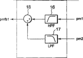
此外,本发明的伺服控制器具有:位置反馈校正部,其将使本轴位置通过高通滤波器而得到的值和另一轴位置通过低通滤波器而得到的值相加,然后对位置反馈信号进行校正;位置控制部,其利用从上述位置反馈校正部输出的校正位置反馈信号,进行位置控制,然后输出速度指令;以及速度控制部,其根据从上述位置控制部输出的速度指令和本轴速度,输出反馈的转矩指令。由于成为近似于主从的形式,即本轴按照另一轴的位置而进行定位,因此,即使是有位置检测误差的情况下,也不会发生轴间的冲突现象。In addition, the servo controller of the present invention has a position feedback correcting section that adds the value obtained by passing the position of the axis through a high-pass filter and the value obtained by passing the position of another axis through a low-pass filter, and then feedbacks the position. Signal correction; position control unit, which uses the corrected position feedback signal output from the above-mentioned position feedback correction unit, to perform position control, and then output a speed command; and a speed control unit, based on the speed command output from the above-mentioned position control unit and this Shaft speed, output feedback torque command. Since it becomes a form similar to master-slave, that is, the axis is positioned according to the position of the other axis, even if there is a position detection error, there will be no conflict between the axes.
此外,本发明的伺服控制器具有速度反馈校正部,其将使上述本轴速度通过高通滤波器而得到的值和另一轴速度通过低通滤波器而得到的值相加,然后对速度反馈信号进行校正,上述速度控制部根据从上述位置控制部输出的速度指令和从上述速度反馈校正部输出的校正速度反馈信号,输出反馈的转矩指令,因此,能够对应于高加减速指令的用途。In addition, the servo controller of the present invention has a speed feedback correction unit that adds the value obtained by passing the above-mentioned axis speed through a high-pass filter and the value obtained by passing the other axis speed through a low-pass filter, and then performs the speed feedback correction. signal correction, the speed control unit outputs a feedback torque command based on the speed command output from the position control unit and the corrected speed feedback signal output from the speed feedback correction unit, so it can be used for applications with high acceleration and deceleration commands .
此外,本发明的伺服控制器,具有:标准模型控制部,其根据位置指令,运算模拟机械的理想动作的模型位置、模型加速度;位置控制部,其利用上述模型位置与本轴位置之间的差值,进行位置控制,然后输出速度指令;速度控制部,其根据从上述位置控制部输出的速度指令和本轴速度,输出反馈的转矩指令;模型转矩校正部,其利用上述本轴位置和另一轴位置,对上述模型加速度进行校正,然后运算模型转矩;以及加法器,其根据上述模型转矩和上述反馈的转矩指令,运算转矩指令,因此,通过模型转矩校正部进行轴间位置偏差的校正,能够利用前馈成分进行校正,即使增大增益,也不易变得不稳定,所以能够获得轴间位置偏差的大幅度抑制效果。In addition, the servo controller of the present invention has: a standard model control unit that calculates the model position and model acceleration for simulating the ideal motion of the machine based on a position command; and a position control unit that uses the distance between the model position and the axis position The difference value is used for position control, and then the speed command is output; the speed control unit outputs the torque command for feedback according to the speed command output from the position control unit and the speed of the shaft; the model torque correction unit uses the speed command of the shaft position and another shaft position, correct the above model acceleration, and then calculate the model torque; and an adder, which calculates the torque command based on the above model torque and the above feedback torque command, thus, correcting the torque by the model The part corrects the inter-axis positional deviation, which can be corrected by the feed-forward component. Even if the gain is increased, it is not easy to become unstable, so a large suppression effect of the inter-axis positional deviation can be obtained.
此外,上述标准模型控制部的构成方式为,根据位置指令,运算模拟机械的理想动作的模型位置、模型速度、模型加速度,并且上述速度控制部的构成方式为,根据从上述位置控制部输出的速度指令和上述模型速度、本轴速度,输出反馈的转矩指令,因此,能够对应于高加减速指令的用途。In addition, the standard model control unit is configured to calculate the model position, model velocity, and model acceleration for simulating the ideal motion of the machine based on the position command, and the speed control unit is configured to calculate the model position, model velocity, and model acceleration based on the output from the position control unit. The speed command, the above-mentioned model speed, and the main axis speed are used to output the torque command for feedback, so it can be used for high acceleration and deceleration commands.
此外,在模型转矩校正部中,相应于时刻或速度指令波形,进行校正动作的开始/停止或校正增益的变更,因此,在发生较大轴间位置偏差时变更为高增益,在其余期间变更为低增益或停止校正,由此能够抑制噪声或干扰的影响,提高模型转矩校正的精度,从而提高轴间位置偏差的抑制性能。In addition, in the model torque correction unit, the start/stop of the correction operation and the change of the correction gain are performed according to the timing or the speed command waveform. Therefore, when a large inter-axis position deviation occurs, the gain is changed to a high gain, and the gain is changed during the rest of the period. Changing to a low gain or stopping the correction can suppress the influence of noise or disturbance, improve the accuracy of the model torque correction, and improve the suppression performance of the inter-axis positional deviation.
此外,在模型转矩校正部中,利用上述本轴位置、另一轴位置、以及上述模型加速度的符号,对上述模型加速度进行校正,然后运算模型转矩。In addition, in the model torque correction unit, the model torque is calculated after correcting the model acceleration using the self-axis position, the other axis position, and the sign of the model acceleration.
此外,在模型转矩校正部中,相应于时刻或速度指令波形,进行校正动作的开始/停止或校正增益的变更,因此,在发生较大轴间位置偏差时变更为高增益,在其余期间变更为低增益或停止校正,由此能够抑制噪声或干扰的影响,提高模型转矩校正的精度,从而提高轴间位置偏差的抑制性能。In addition, in the model torque correction unit, the start/stop of the correction operation and the change of the correction gain are performed according to the timing or the speed command waveform. Therefore, when a large inter-axis position deviation occurs, the gain is changed to a high gain, and the gain is changed during the rest of the period. Changing to a low gain or stopping the correction can suppress the influence of noise or disturbance, improve the accuracy of the model torque correction, and improve the suppression performance of the inter-axis positional deviation.
此外,在模型转矩校正部中,利用上述本轴位置、另一轴位置、以及上述模型加速度的符号,对上述模型加速度进行校正,然后运算模型转矩。In addition, in the model torque correction unit, the model torque is calculated after correcting the model acceleration using the self-axis position, the other axis position, and the sign of the model acceleration.
此外,在模型转矩校正部中,利用上述本轴位置、另一轴位置、以及上述模型加速度的符号,对上述模型加速度进行校正,然后运算模型转矩。In addition, in the model torque correction unit, the model torque is calculated after correcting the model acceleration using the self-axis position, the other axis position, and the sign of the model acceleration.
此外,本发明的伺服控制器具有:标准模型控制部,其根据位置指令,运算模拟机械的理想动作的模型位置、模型加速度;位置反馈校正部,其根据本轴位置和另一轴位置,对位置反馈信号进行校正;位置控制部,其利用上述模型位置与从上述位置反馈校正部输出的校正位置反馈信号之间的差值,进行位置控制,然后输出速度指令;速度反馈校正部,其根据本轴速度和另一轴速度,对速度反馈信号进行校正;速度控制部,其根据从上述位置控制部输出的速度指令和从上述速度反馈校正部输出的校正速度反馈信号,输出反馈的转矩指令;模型转矩校正部,其利用另一轴模型加速度以及上述本轴位置、上述另一轴位置,对上述模型加速度进行校正,然后运算模型转矩;以及加法器,其根据上述模型转矩和上述反馈的转矩指令,运算转矩指令因此,通过模型转矩校正部进行轴间位置偏差的校正,能够利用前馈成分进行完全的校正,从而不会担心引起不稳定,获得轴间位置偏差的抑制效果。In addition, the servo controller of the present invention has: a standard model control unit, which calculates the model position and model acceleration of the ideal movement of the simulated machine according to the position command; The position feedback signal is corrected; the position control part uses the difference between the above-mentioned model position and the corrected position feedback signal output from the above-mentioned position feedback correction part to perform position control, and then outputs a speed command; the speed feedback correction part according to The speed of this shaft and the speed of the other shaft correct the speed feedback signal; the speed control unit outputs the feedback torque according to the speed command output from the position control unit and the corrected speed feedback signal output from the speed feedback correction unit a command; a model torque correcting unit that corrects the model acceleration using another axis model acceleration, the position of the self-axis, and the position of the other axis, and then calculates a model torque; and an adder that calculates a model torque based on the model torque Calculate the torque command with the above-mentioned feedback torque command. Therefore, the inter-axis position deviation can be corrected by the model torque correction unit, and the feed-forward component can be used to perform complete correction, so that the inter-axis position can be obtained without worrying about instability. Bias suppression effect.
此外,上述标准模型控制部的构成方式为,根据位置指令,运算模拟机械的理想动作的模型位置、模型速度、模型加速度,并且上述速度控制部的构成方式为,根据从上述位置控制部输出的速度指令、上述模型速度以及从上述速度反馈校正部输出的校正速度反馈信号,输出反馈的转矩指令,因此,能够对应于高加减速指令的用途。In addition, the standard model control unit is configured to calculate the model position, model velocity, and model acceleration for simulating the ideal motion of the machine based on the position command, and the speed control unit is configured to calculate the model position, model velocity, and model acceleration based on the output from the position control unit. The speed command, the model speed, and the corrected speed feedback signal output from the speed feedback correction unit output a torque command for feedback, and thus can be used for high acceleration and deceleration commands.
附图说明 Description of drawings
图1是表示2轴驱动机械的构成的图。FIG. 1 is a diagram showing the configuration of a two-axis drive machine.
图2是表示在本发明第一实施方式的2轴驱动机械中使用的伺服控制器的构成的图。2 is a diagram showing the configuration of a servo controller used in the two-axis drive machine according to the first embodiment of the present invention.
图3是表示伺服控制器的标准模型控制部1的构成的图。FIG. 3 is a diagram showing the configuration of the standard
图4是表示伺服控制器的标准模型控制部1的另一个构成的图。FIG. 4 is a diagram showing another configuration of the standard
图5是表示本发明第一实施方式的第一轴伺服控制器102a的位置反馈校正部3的构成的图。FIG. 5 is a diagram showing the configuration of the position
图6是表示本发明第一实施方式的第一轴伺服控制器102a的速度反馈校正部6的构成的图。FIG. 6 is a diagram showing the configuration of the speed
图7是表示本发明第一实施方式的第一轴伺服控制器102a的位置反馈校正部3的构成的图。FIG. 7 is a diagram showing the configuration of the position
图8是用于说明本发明第一实施方式的第一轴伺服控制器102a的位置反馈校正部3的增益切换例的图。FIG. 8 is a diagram for explaining an example of gain switching of the position
图9是表示本发明第一实施方式的第一轴伺服控制器102a的速度反馈校正部6的构成的图。FIG. 9 is a diagram showing the configuration of the speed
图10是表示在本发明第二实施方式的2轴驱动机械中使用的伺服控制器的构成的图。10 is a diagram showing the configuration of a servo controller used in a two-axis drive machine according to a second embodiment of the present invention.
图11是表示本发明第二实施方式的第一轴伺服控制器102a的模型转矩校正部32a的构成的图。FIG. 11 is a diagram showing a configuration of a model
图12是用于说明在本发明第二实施方式的第一轴伺服控制器102a的模型转矩校正部32a中,PI校正器46对在PI校正中使用的比例增益Gjp和积分增益Gji进行增益切换的例子的图。12 is a diagram for explaining that in the model
图13是用于说明在本发明第二实施方式的第一轴伺服控制器102a的模型转矩校正部32a中,PI校正器46对在PI校正中使用的比例增益Gjp和积分增益Gji进行增益切换的例子的图。13 is a diagram for explaining that in the model
图14是用于说明在本发明第二实施方式的第一轴伺服控制器102a的模型转矩校正部32a中,PI校正器46对在PI校正中使用的比例增益Gjp和积分增益Gji进行增益切换的例子的图。14 is a diagram for explaining that in the model
图15是表示在本发明第三实施方式的2轴驱动机械中使用的伺服控制器的构成的图。15 is a diagram showing the configuration of a servo controller used in a 2-axis drive machine according to a third embodiment of the present invention.
图16是表示本发明第三实施方式的第一轴伺服控制器102a的模型转矩校正部32b的构成的图。FIG. 16 is a diagram showing the configuration of a model
图17是表示在本发明第四实施方式的2轴驱动机械中使用的伺服控制器的构成的图。17 is a diagram showing the configuration of a servo controller used in a 2-axis drive machine according to a fourth embodiment of the present invention.
图18是表示本发明第四实施方式的第一轴伺服控制器102a的模型转矩校正部32c的构成的图。FIG. 18 is a diagram showing the configuration of a model torque correction unit 32c of the first
具体实施方式 Detailed ways
第一实施方式first embodiment
以下利用图1,对2轴驱动机械的构成和动作进行说明。The configuration and operation of the 2-axis drive machine will be described below using FIG. 1 .
位置指令输出装置101将位置指令pm*输出给第一轴伺服控制器102a和第二轴伺服控制器102b。The position
第一轴伺服控制器102a根据从位置指令输出装置101输出的位置指令pm*和第一轴实际位置pm1,将转矩指令Tm*1输出给第一轴转矩控制单元103a。第一轴转矩控制单元103a相应于转矩指令Tm*1来控制第一轴伺服电动机104a。The first-
第二轴伺服控制器102b根据从位置指令输出装置101输出的位置指令pm*和第二轴实际位置pm2,将转矩指令Tm*2输出给第二轴转矩控制单元103b。第二轴转矩控制单元103b相应于转矩指令Tm*2,来控制第二轴伺服电动机104b。The second-
第一轴伺服电动机104a、第二轴伺服电动机104b分别与第一轴滚轴丝杠105a、第二轴滚轴丝杠105b连接,通过驱动两个轴,使移动台106移动。2轴驱动机械的移动台106上安置有上位结构体107,借助于上位结构体107的位置等,移动台106的重心发生变化。The first-
此外,L是轴间(第一轴滚轴丝杠105a、第二轴滚轴丝杠105b间)的距离,x是从轴间的中心位置到上位结构体107的中心位置的距离。In addition, L is the distance between the shafts (between the first-
此外,采用这样的构成,即在两轴的伺服控制器之间,能够交换彼此的实际位置信息、实际速度信息。In addition, a configuration is adopted in which actual position information and actual speed information can be exchanged between the servo controllers of the two axes.
此外,第一轴伺服控制器102a和第二轴伺服控制器102b的控制是相同的,以下以第一轴伺服控制器102a为例,对伺服控制器的控制进行说明。In addition, the control of the first
以下,利用图2,以第一轴伺服控制器102a为例,对第一实施方式的伺服控制器的构成和处理进行说明。Hereinafter, the configuration and processing of the servo controller of the first embodiment will be described using FIG. 2 and taking the first
标准模型控制部1输入从位置指令输出装置101(未图示)输出的位置指令pm*,运算并输出模型位置pa1、模型速度wa1和模型加速度aa1。The standard
模型转矩运算部2使第一轴的惯量设定值Je1与模型加速度aa1相乘,然后输出模型转矩Ta1。The model
位置反馈校正部3利用作为本轴位置的第一轴位置pm1和作为另一轴位置的第二轴位置pm2,输出第一轴位置反馈信号pmfb1。位置控制部4从减法器5输入模型位置pa1与第一轴位置反馈信号pmfb1之间的偏差,进行位置控制,输出速度指令。The position
速度反馈校正部6利用作为本轴速度的第一轴速度wm1和作为另一轴速度的第二轴速度wm2,输出第一轴速度反馈信号wmfb1。运算器7将模型速度wa1和从位置控制部5输出的速度指令相加,然后减去第一轴速度反馈信号wmfb1,输出校正后的速度指令。速度控制部8根据从运算器7输出的速度指令,输出反馈的转矩指令Tfb1。The speed
加法器9将反馈的转矩指令Tfb1和从模型转矩运算部2输出的模型转矩Ta1相加,作为第一轴的转矩指令Tm*1输出。The
在第一实施方式的伺服控制器中,采用交换彼此的实际位置信息、实际速度信息的构成。在图2中,示出了在第一轴伺服控制器102a中使用第二轴位置pm2和第二轴速度wm2的例子。In the servo controller of the first embodiment, a configuration is adopted in which actual position information and actual speed information are exchanged. In FIG. 2, an example of using the second shaft position pm2 and the second shaft speed wm2 in the first
接下来,利用图3,对标准模型控制部1的构成和处理进行说明。标准模型控制部1,是输出用于根据位置指令来模拟机械的理想动作的模型位置pa1、模型速度wa1、模型加速度aa1的装置。Next, the configuration and processing of the standard
模型位置控制部110输入从位置指令输出装置101(未图示)输出的位置指令pm*与从机械系统模拟部112输出的模型位置pa之间的差值,生成模型速度指令,然后输出给模型速度控制部111。模型速度控制部111输入模型速度指令与模型速度wa之间的差值,生成模型加速度aa,然后输出给机械系统模拟部112。机械系统模拟部112输入模型加速度aa,运算模型速度wa、模型位置pa。The model
此外,利用图4,对标准模型控制部1的另一个结构例和处理进行说明。In addition, another configuration example and processing of the standard
从位置指令输出装置101(未图示)输出的位置指令pm*被用作模型位置pa,速度前馈运算部113输入位置指令pm*,运算模型速度wa,然后输出。加速度前馈运算部114输入模型速度wa,运算模型加速度aa,然后输出。The position command pm* output from the position command output device 101 (not shown) is used as the model position pa, and the velocity
速度前馈运算部113和加速度前馈运算部114,一般由微分器或高通滤波器构成。The velocity
接下来,利用图5,对第一轴伺服控制器102a的位置反馈校正部3的构成和处理进行说明。Next, the configuration and processing of the position
利用减法器11计算出第一轴实际位置pm1与第二轴实际位置pm2之间的偏差(=轴间位置偏差),然后利用系数乘法器13使系数Gp2与通过滤波器12的值相乘。此外,利用加法器15,将利用系数乘法器14使系数Gp1与第一轴实际位置pm1相乘得到的值和利用系数乘法器13乘以系数Gp2而得到的值相加,计算出第一轴位置反馈信号pmfb1。The difference between the first axis actual position pm1 and the second axis actual position pm2 (=interaxial position error) is calculated by the
获得第一轴位置反馈信号pmfb1与位置指令pa1的差值,然后用于位置控制中。Obtain the difference between the first axis position feedback signal pmfb1 and the position command pa1, and then use it in position control.
用低通滤波器来构成输入轴间位置偏差的滤波器12,由此能够防止高频成分的通过,与上述专利文献2相比,不易引起振动,因此能够进一步提高增益,从而能够提高轴间位置偏差的抑制性能。By using a low-pass filter to configure the
接下来,利用图6,对第一轴伺服控制器102a的速度反馈校正部6的构成和处理进行说明。Next, the configuration and processing of the speed
利用减法器21计算出第一轴实际速度wm1和第二轴实际速度wm2之间的偏差(=轴间速度偏差),然后利用系数乘法器23,使系数Gw2与通过滤波器22后得到的值相乘。此外,利用加法器25,使利用系数乘法器24将系数Gw1与第一轴实际速度wm1相乘而得到的值和利用系数乘法器23乘以系数Gw2而得到的值相加,计算出第一轴速度反馈信号wmfb1。The deviation between the first shaft actual speed wm1 and the second shaft actual speed wm2 (= inter-shaft speed deviation) is calculated by the
获得第一轴速度反馈信号wmfb1与速度指令wa1的差值,然后用于速度控制中。Obtain the difference between the first shaft speed feedback signal wmfb1 and the speed command wa1, and then use it in speed control.
用低通滤波器来构成输入轴间速度偏差的滤波器22,由此能够防止高频成分的通过,与上述专利文献2相比,不易引起振动,因此能够进一步提高增益,从而能够提高轴间速度偏差的抑制性能。By using a low-pass filter to configure the
接下来,利用图7,对位置反馈校正部3的另一个结构例和处理进行说明。如果将图5所示的系数乘法器13的系数Gp2和系数乘法器14的系数Gp1设定为Gp1=—Gp2>0,则位置反馈校正部的构成与图7的大致等价。Next, another configuration example and processing of the position
利用加法器18,使第一轴实际位置pm1通过高通滤波器16后得到的值和第二轴实际位置pm2通过低通滤波器17后得到的值相加,输出第一轴位置反馈信号pmfb1。The
在图7的构成中,高频成分反馈本轴(第一轴)的实际位置,低频成分反馈另一轴(第二轴)的实际位置。其结果是,成为近似于主从(master slave)的形式,即本轴按照另一轴的位置而进行定位,因此,即使是有位置检测误差的情况下,也不会发生轴间的冲突现象。In the configuration of FIG. 7 , the high-frequency component feeds back the actual position of the own axis (the first axis), and the low-frequency component feeds back the actual position of the other axis (the second axis). As a result, it becomes a form similar to a master slave (master slave), that is, the axis is positioned according to the position of the other axis, so even if there is a position detection error, there will be no conflict between the axes .
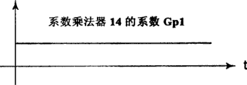
以下利用图8,对位置反馈校正部3中的系数乘法器13的系数Gp2和系数乘法器14的系数Gp1的切换例进行说明。图8(a)是表示速度指令变化的图,图8(b)是表示系数乘法器14的系数Gp1的变化的图,图8(c)是表示系数乘法器13的系数Gp2的变化的图。Next, an example of switching between the coefficient Gp2 of the
在速度指令生成中,由于发生轴间位置偏差,所以如图8(c)所示,通过系数乘法器13的系数Gp2>0,来进行轴间位置偏差的抑制,在停止期间和停止后,使系数Gp2=—Gp1=—1,来切换为主从控制,防止轴间的冲突。During the generation of the speed command, since the inter-axis position deviation occurs, as shown in Figure 8(c), the coefficient Gp2>0 of the
通过使系数乘法器13、14的系数值可变,能够容易地切换控制器的构成,从而能够抑制轴间位置偏差,同时防止轴间的冲突。By making the coefficient values of the
接下来,利用图9,对速度反馈校正部6的另一个构成例和处理进行说明。如果将图6所述的系数乘法器23的系数Gw2和系数乘法器24的系数Gw1设定为Gw1=—Gw2>0,则速度反馈校正部的构成与图9的大致等价。Next, another configuration example and processing of the speed
利用加法器28,将第一轴实际速度wm1通过高通滤波器26后得到的值和第二轴实际速度wm2通过低通滤波器27后得到的值相加,输出第一轴速度反馈信号wmfb1。The
在图9的构成中,高频成分反馈本轴(第一轴)的实际速度,低频成分反馈另一轴(第二轴)的实际速度。其结果是,成为近似于主从(master slave)的形式,即本轴按照另一轴的速度而决定速度,因此,即使是有速度检测误差的情况下,也不会发生轴间的冲突现象。In the configuration of FIG. 9 , the high-frequency component feeds back the actual speed of the own axis (first axis), and the low-frequency component feeds back the actual speed of the other axis (second axis). As a result, it becomes a form similar to a master-slave, that is, the speed of this axis is determined according to the speed of the other axis. Therefore, even if there is a speed detection error, there will be no conflict between the axes. .
由于第一实施方式的伺服控制器对位置偏差和速度偏差两者进行校正,所以在应用于2轴驱动机械的控制中的情况下,与上述专利文献2相比,能够以低的增益获得同等程度的效果,因此能够更稳定地进行机械的轴间位置偏差抑制。Since the servo controller of the first embodiment corrects both the position deviation and the speed deviation, when it is applied to the control of a 2-axis drive machine, it can achieve the same performance with a lower gain than that of the above-mentioned
此外,由于采用防止轴间位置偏差的高频成分通过的构成,所以与上述专利文献2相比,不易引起振动,从而也能够应用于低刚性的机械。In addition, since the passage of the high-frequency component that prevents the positional deviation between the shafts is adopted, compared with the above-mentioned
此外,能够简单地切换为主从控制,能够防止轴间的冲突,从而也能够应用于有位置检测误差的机械。In addition, master-slave control can be switched easily, and collision between axes can be prevented, so it can also be applied to machines with position detection errors.
由于第一实施方式的伺服控制器只要在现有的进行位置反馈和速度反馈的部分中加入了位置反馈校正部、速度反馈校正部即可,所以可以容易地替换现有的伺服控制器。此外,由于能够用1种构成来切换为多种控制构造,所以能够减轻软件的负担。Since the servo controller of the first embodiment only needs to add a position feedback correcting unit and a velocity feedback correcting unit to the existing portion that performs position feedback and velocity feedback, the existing servo controller can be easily replaced. In addition, since it is possible to switch between multiple control structures with one structure, the burden on software can be reduced.
在上述第一实施方式中,对采用使用了根据位置指令来运算模型位置、模型速度、模型加速度的标准模型控制部这样的构成,位置控制部根据模型位置与从位置反馈校正部输出的校正位置反馈信号之间的差值,进行位置控制,然后输出速度指令,并且,速度控制部根据从位置控制部输出的速度指令、模型速度以及校正速度反馈信号,输出反馈的转矩指令的例子进行了说明,但也可以不使用标准模型控制部。但是,在指令脉冲不平滑,或者位置指令急剧变化的情况下,通过使用标准模型控制部,可以改善目标值响应性能。In the above-mentioned first embodiment, for the configuration using the standard model control unit that calculates the model position, model velocity, and model acceleration based on the position command, the position control unit uses the model position and the corrected position output from the position feedback correction unit. The difference between the feedback signals, the position control is performed, and then the speed command is output, and the speed control part outputs the feedback torque command according to the speed command output from the position control part, the model speed and the correction speed feedback signal. Instructions, but it is also possible not to use the standard model control section. However, when the command pulse is not smooth or the position command changes rapidly, the target value response performance can be improved by using the standard model control unit.
第二实施方式second embodiment
以下利用图10,以第一轴伺服控制器102a为例,对第二实施方式的伺服控制器的构成和处理进行说明。Hereinafter, using FIG. 10 , the configuration and processing of the servo controller of the second embodiment will be described by taking the first
标准模型控制部1输入从位置指令输出装置101(未图示)输出的位置指令pm*,运算并输出模型位置pa1、模型速度wa1和模型加速度aa1。The standard
模型转矩校正部32a利用模型加速度aa1和作为本轴位置的第一轴实际位置pm1和作为另一轴位置的第二轴实际位置pm2,输出模型转矩Ta1。The model
位置控制部34从减法器35输入模型位置pa1与作为本轴位置的第一轴实际位置pm1之间的偏差,进行位置控制,输出速度指令。The
运算器37使模型速度wa1和从位置控制部34输出的速度指令相加,然后减去作为本轴速度的第一轴实际速度wm1,输出校正后的速度指令。The
速度控制部38根据从运算部37输出的速度指令,输出反馈的转矩指令Tfb1。The
加法器39使反馈的转矩指令Tfb1和从模型转矩校正部32a输出的模型转矩Ta1相加,然后作为第一轴的转矩指令Tm*1而输出。The
第二实施方式的第一轴伺服控制器的构成为,将第一实施方式的第一轴伺服控制器中的模型转矩运算部2替换为模型转矩校正部32a。The first-axis servo controller of the second embodiment is configured by replacing the model
在第二实施方式的伺服控制器中,采用交换彼此的实际位置信息的构成。在图10中,示出了在第一轴伺服控制器102a中使用第二轴位置pm2的例子。In the servo controller of the second embodiment, a configuration is employed to exchange actual position information between each other. In FIG. 10 , an example of using the second axis position pm2 in the first
接下来,利用图11,对模型转矩校正部32a的构成和处理进行说明。Next, the configuration and processing of the model
使从标准模型控制部1(未图示)输出的模型加速度aa1通过高通滤波器41后,在符号检测器42中检测出模型加速度的符号。After passing the model acceleration aa1 output from the standard model control unit 1 (not shown) through the high-
利用乘法器45,在使由减法器43求出的第一轴实际位置pm1和第二轴实际位置pm2之间的偏差通过高通滤波器44后得到的值上,附加由符号检测器42求出的模型加速度的符号,然后输出给PI校正器46。The
PI校正器46利用比例增益Gjp和积分增益Gji来进行PI校正,输出惯量校正值△Je1。The
利用减法器47,从由标称的系数乘法器48设定的模型惯量值Je1中减去惯量校正值△Je1。The inertia correction value ΔJe1 is subtracted from the model inertia value Je1 set by the
利用乘法器49,使由减法器47求出的值与从标准模型控制部1(未图示)输出的模型加速度aa1相乘,从而得到校正后的模型转矩Ta1。The value obtained by the
在第二实施方式的第一轴伺服控制器102a的模型转矩校正部32a中,如果由标称的系数乘法器48设定的模型惯量值Je1与实际的驱动惯量一致,则能够借助于模型转矩Ta1而使得实际的位置与模型位置大致一致地动作。In the model
此外,在模型惯量值Je1有误差的情况下,根据轴间位置偏差进行校正,使得与实际的惯量一致。例如,在上位结构体位于相反侧,实际的惯量由于负载不平衡而比模型惯量值Je1小的情况下,如果加速度的变化为正,则产生正的轴间位置偏差,如果加速度的变化为负,则产生负的轴间位置偏差。因此,利用模型加速度aa1通过高通滤波器后得到的值的极性,使轴间位置偏差校正输入反转,由此能够总是向使模型惯量值变小的方向,即与实际的惯量一致的方向校正。通过这样的校正,控制第一轴位置和第二轴位置使得它们一致,从而抑制了轴间位置偏差。In addition, when there is an error in the model inertia value Je1, it is corrected based on the inter-axis positional deviation so as to match the actual inertia. For example, when the upper structure is on the opposite side and the actual inertia is smaller than the model inertia value Je1 due to load imbalance, if the change in acceleration is positive, a positive inter-axis position deviation will occur, and if the change in acceleration is negative , a negative inter-axis position deviation is produced. Therefore, by using the polarity of the value obtained by passing the high-pass filter of the model acceleration aa1, the inter-axis position deviation correction input is inverted, so that the value of the model inertia can always be reduced, that is, the actual inertia can be matched. Orientation correction. By such correction, the first axis position and the second axis position are controlled so that they coincide, thereby suppressing the inter-axis positional deviation.
此外,根据控制器或机械的条件,有时在加速时产生正的轴间位置偏差,在减速时产生负的轴间位置偏差。在这样的情况下,如果将高通滤波器的增益设定为0等较小值,则同样能够总是对模型惯量值进行校正,从而抑制轴间位置偏差。In addition, depending on the conditions of the controller or the machine, a positive inter-axis position deviation may occur during acceleration, and a negative inter-axis position deviation may occur during deceleration. In such a case, if the gain of the high-pass filter is set to a small value such as 0, it is also possible to always correct the model inertia value and suppress the inter-axis positional deviation.
高通滤波器、PI校正器46的增益是相应于标准模型控制部、位置控制部、速度控制部的响应、机械的构成而决定的,但高通滤波器的增益,根据条件,可以为0,也可以为直达项。The gain of the high-pass filter and
以下利用图12,对PI校正器46进行的用于PI校正的比例增益Gjp和积分增益Gji的增益切换的例子进行说明。图12(a)是表示速度指令变化的图,图12(b)是表示比例增益Gjp和积分增益Gji的变化的图。An example of gain switching between the proportional gain Gjp and the integral gain Gji for PI correction performed by the
由于轴间位置偏差在加减速中途和加减速开始点、结束点等产生较大的值,所以对于PI校正增益,在这些点的附近,进行可提高增益等的可变增益。Since the inter-axis position deviation has a large value in the middle of acceleration and deceleration, the acceleration and deceleration start point, end point, etc., for the PI correction gain, a variable gain that can increase the gain or the like is performed in the vicinity of these points.
在图12中,示出了在停止时使PI增益为0,在速度指令wm*进入的瞬间,使增益变为最大,然后单独减小,在某一恒定期间内,使其落到某一恒定值的例子。通过这样的构成,由于在校正中进入很多重要信号的期间,能够进行更多的校正,所以不易受噪声、干扰等的影响,从而能够提高校正惯量运算的运算精度。In Fig. 12, it is shown that the PI gain is set to 0 at the time of stop, and at the moment when the speed command wm* enters, the gain becomes the maximum, and then decreases independently, and makes it fall to a certain value within a certain constant period. Example of a constant value. With such a configuration, more corrections can be performed when many important signals are involved in the correction, so it is less susceptible to the influence of noise, interference, etc., and the calculation accuracy of the correction inertia calculation can be improved.
在上述图12中,示出了在发生较大轴间位置偏差的加减速中途和加减速开始点、结束点附近提高增益的例子,但在预先知道上位结构体等的动作时序的情况下,通过与沿该时序的时刻对应地来进行可变增益,同样能够提高运算精度。以下利用图13、图14,对另一个增益的可变例进行说明。图13(a)是表示速度指令变化的图,图13(b)是表示比例增益Gjp和积分增益Gji的变化的图。此外,图14(a)是表示速度指令变化的图,图14(b)是表示比例增益Gjp和积分增益Gji的变化的图。In the above-mentioned Fig. 12, an example is shown in which the gain is increased in the middle of acceleration and deceleration where a large inter-axis position deviation occurs, and near the start and end points of acceleration and deceleration. By performing a variable gain corresponding to the timing along this sequence, it is also possible to improve calculation accuracy. Another variable example of the gain will be described below using FIGS. 13 and 14 . FIG. 13( a ) is a graph showing changes in the speed command, and FIG. 13( b ) is a graph showing changes in the proportional gain Gjp and the integral gain Gji. In addition, FIG. 14( a ) is a diagram showing changes in the speed command, and FIG. 14( b ) is a diagram showing changes in the proportional gain Gjp and the integral gain Gji.
图13中是在加速时和减速时轴间位置偏差变大情况下的增益的可变例,其对于校正运算的精度提高和轴间位置偏差的抑制是有效的。FIG. 13 shows a variable example of the gain when the inter-axial positional deviation becomes large during acceleration and deceleration, which is effective for improving the accuracy of the correction calculation and suppressing the inter-axial positional deviation.
此外,图14是在加减速开始点、结束点轴间位置偏差变大情况下的增益的可变例,其对于校正运算的精度提高和轴间位置偏差的抑制是有效的。In addition, FIG. 14 shows a variable example of the gain when the inter-axis position deviation becomes large at the acceleration and deceleration start point and end point, which is effective for improving the accuracy of the correction calculation and suppressing the inter-axis position deviation.
模型转矩校正部32a不限于上述方式,例如,可以使用如下方式来替代PI校正器46,所述方式是利用以P控制或PID控制、相位前进补偿、逐次最小二乘法为代表的统计方法的方式。此外,在上述说明中,示出了使用轴间位置偏差通过高通滤波器后得到的值的例子,但也可以直接使用轴间位置偏差,并且对轴间位置偏差设置死区(dead zone)。The model
在将第二实施方式的伺服控制器应用于2轴驱动机械的控制中的情况下,由于对轴间位置偏差的发生要因直接且实时地校正,所以即使在由于移动台的上位结构体的动作等而使得负载不平衡发生变化的情况下,也能够抑制轴间位置偏差。When the servo controller of the second embodiment is applied to the control of a 2-axis drive machine, since the cause of the positional deviation between the axes is corrected directly and in real time, even when the movement of the upper structure of the moving table Even when the load unbalance changes, etc., it is also possible to suppress the positional deviation between the shafts.
此外,与上述专利文献2不同,由于是在前馈侧进行校正,所以不必将增益设定得很高,就能够稳定且高速地进行轴间位置偏差的抑制,从而也能够应用于刚性不高的机械中。此外,在利用PI校正等的情况下,由于不必进行数学公式运算,所以能够以较少的运算量得到抑制效果,并且能够容易地应用于不能正确地得到2轴间距离或刚性、各部分的质量等机械常数的机械。In addition, unlike the above-mentioned
第二实施方式的伺服控制器,由于只要将现有的系数乘法器即模型转矩运算部分变更为模型转矩校正部即可,所以能够容易地替换现有的伺服控制器。The servo controller according to the second embodiment can easily replace the existing servo controller because it only needs to change the model torque calculation part which is the existing coefficient multiplier to the model torque correction part.
此外,通过相应于速度指令或时刻来进行可变增益,能够进一步提高校正惯量值的运算精度,从而能够提高轴间位置偏差的抑制性能。In addition, by performing a variable gain according to the speed command or time, the calculation accuracy of the correction inertia value can be further improved, and the performance of suppressing the inter-axis positional deviation can be improved.
在上述第二实施方式中,示出了标准模型控制部采用根据位置指令而运算模型位置、模型速度、模型加速度的构成,速度控制部根据从位置控制部输出的速度指令、模型速度以及本轴速度,输出反馈的转矩指令的例子,但也可以不使用模型速度。但是,在高加减速指令的用途中,通过使用模型速度,能够提高轴间位置偏差的抑制性能。In the above-mentioned second embodiment, the standard model control unit is shown to be configured to calculate the model position, model velocity, and model acceleration based on the position command. Velocity is an example of outputting a torque command for feedback, but the model velocity may not be used. However, in the application of high acceleration/deceleration commands, using the model velocity can improve the performance of suppressing position deviation between axes.
第三实施方式third embodiment
以下利用图15,以第一轴伺服控制器102a为例,对第三实施方式的伺服控制器的构成和处理进行说明。在图15中,1、34~39与图10的相同,所以省略其说明。The configuration and processing of the servo controller according to the third embodiment will be described below using FIG. 15 and taking the first
模型转矩校正部32b利用从标准模型控制部1输出的第一轴模型加速度aa1和从第二轴伺服控制器(未图示)的标准模型控制部输出的第二轴模型加速度aa2,输出校正后的模型转矩Ta1。The model
在第三实施方式的伺服控制器中,采用交换彼此的模型加速度信息的构成。在图15中,示出了在第一轴伺服控制器102a中使用第二轴模型加速度aa2的例子。In the servo controller of the third embodiment, a configuration is employed to exchange mutual model acceleration information. In FIG. 15, an example of using the second-axis model acceleration aa2 in the first-
以下利用图16,对模型转矩校正部32b的构成和处理进行说明。The configuration and processing of the model
利用加法器53,将利用系数乘法器51使系数J11与从标准模型控制部31输出的第一轴模型加速度aa1相乘而得到的值和利用系数乘法器52使系数J12与从第二轴伺服控制器(未图示)的标准模型控制部输出的第二轴模型加速度aa2相乘而得到的值相加,输出校正后的模型转矩Ta1。其中,J11是为系数乘法器51设定的自身惯量,J12是为系数乘法器设定的干涉惯量。The
此外,对于图1所示构成的2轴驱动机械的机械惯量,如果设第一轴惯量为J1,第二轴惯量为J2,移动台惯量为J3,上位结构体的惯量为J4,从这4个惯量得到的重心附近的转动力矩为J0,建立运动方程式,则能够由下式得到自身惯量J11和干涉惯量J12。In addition, regarding the mechanical inertia of the 2-axis drive machine configured as shown in Fig. 1, if the inertia of the first axis is J1, the inertia of the second axis is J2, the inertia of the mobile table is J3, and the inertia of the upper structure is J4, from these 4 The rotational moment near the center of gravity obtained by the inertia is J0, and the motion equation is established, then the own inertia J11 and the interference inertia J12 can be obtained by the following formula.
J11=J1+J3/4+(1/2—x/L)2·J4+J0/L2 J11=J1+J3/4+(1/2—x/L) 2 J4+J0/L 2
J12=J1+J3/4+(1/2—x/L)2·J4+J0/L2 J12=J1+J3/4+(1/2—x/L) 2 J4+J0/L 2
其中,L是轴间距离,x是从轴间中心位置到上位结构体中心位置的距离。Among them, L is the distance between axes, and x is the distance from the center position of the axis to the center position of the upper structure.
因此,通过将图16的系数乘法器51的J11和系数乘法器52的J12设定为上式的值,可以与上述第二实施方式同样地,得到使实际位置与模型位置一致的正确模型转矩,向第一轴位置和第二轴位置一致的方向进行控制,从而抑制轴间位置偏差。Therefore, by setting J11 of the
在移动台的负载分配是固定的情况下,只要将系数乘法器51、系数乘法器52的设定值设定为常数即可,但在例如上位结构体的位置发生变化等、负载分配变动的情况下,只要从上位的控制器等变更设定值即可。例如,可以考虑接受上式的x(从轴间中心位置到上位结构体中心位置的距离)的值,然后进行运算并设定的方法,或者在上位的控制器中运算惯量值,然后接受并变更参数值的方法等。When the load distribution of the mobile station is fixed, the setting values of the
在将第三实施方式的伺服控制器应用于2轴驱动机械的控制中的情况下,能够利用上述动作抑制轴间位置偏差。此外,有这样的优点,即,由于完全是借助于前馈部分来进行校正,所以即使在增益设定值错误等情况下,也不会变得不稳定。在预先知道机械常数的情况下,或从上位控制器等得到信息的情况下,第三实施方式的伺服控制器与第一实施方式和第二实施方式相比,能够减轻伺服控制器侧的软件负担。When the servo controller of the third embodiment is applied to the control of a two-axis drive machine, the above-mentioned operation can suppress the positional deviation between the axes. In addition, there is an advantage that, since the correction is performed entirely by means of the feedforward portion, it does not become unstable even if the gain setting value is wrong or the like. When the mechanical constants are known in advance, or when the information is obtained from a host controller, etc., the servo controller of the third embodiment can reduce the software on the servo controller side compared with the first and second embodiments. burden.
此外,该伺服控制器与第二实施方式的情况相同,只要将现有的系数乘法器即模型转矩运算部分变更为校正前馈部即可,所以能够容易地替换现有实施例的伺服控制器。In addition, this servo controller is the same as the case of the second embodiment, and only needs to change the existing coefficient multiplier, that is, the model torque calculation part, into a correction feedforward part, so the servo control of the conventional embodiment can be easily replaced. device.
在上述第三实施方式中,示出了标准模型控制部采用根据位置指令而运算模型位置、模型速度、模型加速度的构成,速度控制部根据从位置控制部输出的速度指令、模型速度以及从速度反馈校正部输出的校正速度反馈信号,输出反馈的转矩指令的例子,但也可以不使用模型速度。但是,在高加减速指令的用途中,通过使用模型速度,能够提高轴间位置偏差的抑制性能。In the above-mentioned third embodiment, it is shown that the standard model control unit is configured to calculate the model position, model velocity, and model acceleration based on the position command, and the speed control unit calculates the model position, model velocity, and slave velocity based on the speed command, model velocity, and slave velocity output from the position control unit. The corrected speed feedback signal output by the feedback correction unit is an example of outputting a torque command for feedback, but the model speed may not be used. However, in the application of high acceleration/deceleration commands, using the model velocity can improve the performance of suppressing position deviation between axes.
第四实施方式Fourth Embodiment
以下利用图17,对第四实施方式的第一轴伺服控制器的构成和处理进行说明。在图17中,1、3~9与图2的相同,所以省略其说明。The configuration and processing of the first axis servo controller according to the fourth embodiment will be described below using FIG. 17 . In FIG. 17, 1, 3 to 9 are the same as those in FIG. 2, so description thereof will be omitted.
模型转矩校正部32c利用从标准模型控制部1输出的第一轴模型加速度aa1、从第二轴伺服控制器(未图示)的标准模型控制部输出的第二轴模型加速度aa2以及作为本轴位置的第一轴位置pm1和作为另一轴位置的第二轴位置pm2,输出校正后的模型转矩Ta1。The model torque correction unit 32c uses the first axis model acceleration aa1 output from the standard
以下利用图18,对模型转矩校正部32c的构成和处理进行说明。在图18中,41~46与图11的相同,所以省略其说明。The configuration and processing of the model torque correction unit 32c will be described below using FIG. 18 . In FIG. 18 , 41 to 46 are the same as those in FIG. 11 , so description thereof will be omitted.
PI校正器46利用比例增益Gjp和积分增益Gji来进行PI校正,输出惯量校正值△Je1。The
利用减法器54,从自身惯量J11中减去惯量校正值△Je1,然后利用乘法器55,使由减法器54求出的值与从标准模型控制部1(未图示)输出的模型加速度aa1相乘。利用减法器56,从干涉惯量J12中减去惯量校正值△Je1,然后利用乘法器57,使由减法器56求出的值与从第二轴伺服控制器(未图示)的标准模型控制部输出的第二轴模型加速度aa2相乘。其中,自身惯量J11和干涉惯量J12,使用与在图16中为标称的系数乘法器51、标称的系数乘法器52设定的数值相同的数值。The inertia correction value ΔJe1 is subtracted from the own inertia J11 by the
利用加法器58,使由乘法器55求出的值和由乘法器57求出的值相加,从而得到校正后的模型转矩Ta1。The value obtained by the
在第四实施方式的第一轴伺服控制器的模型转矩校正部32c中,通过从自身惯量J11中减去由PI校正器46得到的惯量校正值△Je1来进行校正,并且将由PI校正器46得到的惯量校正值△Je1与干涉惯量J12相加来进行校正,然后将这些校正后的值分别与模型加速度aa1、aa2相乘而得到的值相加,作为模型转矩Ta1。In the model torque correcting section 32c of the first axis servo controller of the fourth embodiment, correction is performed by subtracting the inertia correction value ΔJe1 obtained by the
在第四实施方式的第一轴伺服控制器中,作为机械常数而预先得到的负载不平衡,与第三实施方式同样地,通过由标称的系数乘法器51、52设定的自身惯量J11、干涉惯量J12来进行校正。但是,对于机械常数有偏差时产生的不平衡量,与第二实施方式同样地,通过由PI校正器46得到的惯量校正值△Je1来进行校正。通过这些惯量校正,能够有效地抑制轴间位置偏差。对于即使如此也没有完全抑制的轴间位置偏差,与第一实施方式同样地,通过位置反馈校正部3和速度反馈校正部6来抑制。由此,能够得到非常大的轴间位置偏差的抑制效果。In the first axis servo controller of the fourth embodiment, the unbalanced load obtained in advance as a mechanical constant is passed through the self-inertia J11 set by the
在将第四实施方式的第一轴伺服控制器应用于2轴驱动机械的控制中的情况下,对于作为机械常数而预先得到的负载不平衡,与第三实施方式同样地进行前馈校正,对于该常数有偏差时产生的不平衡量,与第二实施方式同样地进行校正,对于即使如此也没有完全抑制的轴间位置偏差,与第一实施方式同样地通过反馈来进行校正,所以能够得到非常大的轴间位置偏差的抑制效果。When the first-axis servo controller of the fourth embodiment is applied to the control of a two-axis drive machine, feed-forward correction is performed in the same manner as in the third embodiment for the load unbalance obtained in advance as a machine constant, The unbalance amount that occurs when this constant varies is corrected in the same manner as in the second embodiment, and the inter-axis positional deviation that cannot be completely suppressed is corrected by feedback in the same manner as in the first embodiment, so that it is possible to obtain Suppression effect of extremely large inter-axis position deviation.
此外,通过同时使用第一~第三实施方式的技术,不必将模型转矩校正部的PI校正增益或位置反馈校正部、速度反馈校正部的增益设定得很大,所以能够稳定地得到所希望的轴间位置偏差的抑制效果。In addition, by using the techniques of the first to third embodiments together, it is not necessary to set the PI correction gain of the model torque correction unit or the gains of the position feedback correction unit and the speed feedback correction unit to be large, so it is possible to stably obtain the The effect of suppressing the desired inter-axis positional deviation.
在上述第四实施方式的第一轴伺服控制器中,对同时使用上述第一~第三实施方式所示的技术的例子进行了说明,但可以根据用途,仅同时使用上述第一~第三实施方式所示的技术中的2个。此外,也可以对应于速度指令或时刻,切换使用上述第一~第三实施方式所示的技术。In the first-axis servo controller according to the fourth embodiment described above, an example in which the technologies shown in the first to third embodiments are used together is described, but only the first to third technologies described above may be used at the same time depending on the application. Two of the techniques described in the embodiments. In addition, the techniques described in the above-mentioned first to third embodiments may be switched and used in accordance with the speed command or the time.
此外,在上述说明中,对将本发明的伺服控制器应用于2轴驱动机械的例子进行了说明,但本发明的适用对象不限于2轴驱动机械,在3轴或3轴以上的多个轴的情况下,也可以利用例如本轴以外的多个轴的平均位置与本轴位置之间的位置偏差等来应用本发明。此外,构成2轴驱动机械的2轴的同步不仅限于1:1,在1:N的情况下,将该比值作为系数相乘,同样能够应用本发明。In addition, in the above description, an example in which the servo controller of the present invention is applied to a 2-axis drive machine has been described, but the application object of the present invention is not limited to a 2-axis drive machine. In the case of an axis, the present invention can also be applied using, for example, the positional deviation between the average position of a plurality of axes other than the own axis and the position of the own axis. In addition, the synchronization of the two axes constituting the two-axis drive machine is not limited to 1:1, and in the case of 1:N, the ratio is multiplied as a coefficient, and the present invention can be similarly applied.
此外,以上对使用滚轴丝杠作为执行机构的例子进行了说明,但不限于滚轴丝杠。In addition, although the example which used the roller screw as an actuator was demonstrated above, it is not limited to a roller screw.
此外,对于使用本发明的伺服控制器的机械,不仅适合直线运动系统的同步控制,也同样适合转动系统的同步控制。In addition, the machine using the servo controller of the present invention is not only suitable for the synchronous control of the linear motion system, but also suitable for the synchronous control of the rotary system.
工业实用性Industrial Applicability
如上所述,本发明的伺服控制器,能够应用于低刚性机械或存在位置检测误差这样的2轴驱动机械,所以适用于多轴驱动机械的同步控制。As described above, the servo controller of the present invention can be applied to a low-rigidity machine or a two-axis drive machine such as a position detection error, so it is suitable for synchronous control of a multi-axis drive machine.
Claims (15)
Applications Claiming Priority (1)
| Application Number | Priority Date | Filing Date | Title |
|---|---|---|---|
| PCT/JP2003/004642 WO2004092859A1 (en) | 2003-04-11 | 2003-04-11 | Servo controller |
Publications (2)
| Publication Number | Publication Date |
|---|---|
| CN1745352A CN1745352A (en) | 2006-03-08 |
| CN100470433C true CN100470433C (en) | 2009-03-18 |
Family
ID=33193204
Family Applications (1)
| Application Number | Title | Priority Date | Filing Date |
|---|---|---|---|
| CNB038260425A Expired - Fee Related CN100470433C (en) | 2003-04-11 | 2003-04-11 | servo controller |
Country Status (7)
| Country | Link |
|---|---|
| US (1) | US7671553B2 (en) |
| JP (1) | JP4289299B2 (en) |
| CN (1) | CN100470433C (en) |
| DE (1) | DE10394201T5 (en) |
| GB (1) | GB2414818B (en) |
| TW (1) | TWI220812B (en) |
| WO (1) | WO2004092859A1 (en) |
Cited By (2)
| Publication number | Priority date | Publication date | Assignee | Title |
|---|---|---|---|---|
| CN109690441A (en) * | 2017-04-12 | 2019-04-26 | 三菱电机株式会社 | Synchronous control system and control device |
| TWI683196B (en) * | 2015-02-13 | 2020-01-21 | 日商山洋電氣股份有限公司 | Motor control apparatus |
Families Citing this family (55)
| Publication number | Priority date | Publication date | Assignee | Title |
|---|---|---|---|---|
| JP4070744B2 (en) * | 2004-04-28 | 2008-04-02 | ファナック株式会社 | Synchronous control device |
| US7541766B1 (en) * | 2004-06-01 | 2009-06-02 | Sato Jeffrey S | System and method for the intelligent use of software deadband control in a control system |
| ES2309603T3 (en) * | 2005-02-04 | 2008-12-16 | Trumpf Werkzeugmaschinen Gmbh + Co. Kg | PROCEDURE FOR THE DIVISION OF A RELATIVE MOVEMENT BETWEEN A WORK PIECE AND A TOOL OF A MACHINE-TOOL. |
| JP4361071B2 (en) * | 2005-07-08 | 2009-11-11 | ファナック株式会社 | Servo control device |
| JP4881138B2 (en) * | 2006-12-05 | 2012-02-22 | 株式会社ニフコ | Motor drive control device, electric assist device, and responsive feedback control method |
| JP4673326B2 (en) * | 2007-01-11 | 2011-04-20 | オークマ株式会社 | Rotary shaft position control device |
| US7986118B2 (en) * | 2007-04-23 | 2011-07-26 | Honda Motor Co., Ltd. | Open-loop torque control on joint position-controlled robots |
| KR101048938B1 (en) * | 2007-05-01 | 2011-07-12 | 도시바 미쓰비시덴키 산교시스템 가부시키가이샤 | Drive of rolling roll electric motor |
| DE112009000680B4 (en) * | 2008-03-28 | 2026-03-05 | Thk Co., Ltd. | Servo motor position control device |
| CN102245349B (en) * | 2008-12-09 | 2015-05-27 | 三菱电机株式会社 | Machine motion trajectory measuring device, numerically controlled machine tool, and machine motion trajectory measuring method |
| JP4677037B2 (en) * | 2009-01-20 | 2011-04-27 | ファナック株式会社 | Servo controller that suppresses backlash |
| JP5229396B2 (en) * | 2009-09-30 | 2013-07-03 | 三菱電機株式会社 | Positioning control device |
| US8241240B2 (en) * | 2009-11-09 | 2012-08-14 | Medtronic Xomed, Inc. | Adjustable valve setting with motor control |
| JP5422368B2 (en) * | 2009-12-24 | 2014-02-19 | 三菱重工業株式会社 | Servo control device |
| DE102010001781A1 (en) * | 2010-02-10 | 2011-08-11 | Siemens Aktiengesellschaft, 80333 | Method for movement of machine element of machine tool in automatic control engineering, involves storing reference values when movement restrictions of reference values for movement portions are held |
| DE102010001829B4 (en) * | 2010-02-11 | 2011-09-01 | Siemens Aktiengesellschaft | Method for moving a machine element of a machine from automation technology and drive system |
| TWI407279B (en) * | 2010-03-08 | 2013-09-01 | Univ Ishou | Positioning controller |
| JP2012088827A (en) * | 2010-10-18 | 2012-05-10 | Mitsubishi Heavy Ind Ltd | Load inertia estimation method and control parameter adjustment method |
| JP2012104047A (en) * | 2010-11-12 | 2012-05-31 | Mitsubishi Electric Corp | Servo controller |
| CN103057262A (en) * | 2011-10-24 | 2013-04-24 | 致伸科技股份有限公司 | Printing control method for printing device and printing device |
| JP5747831B2 (en) * | 2012-02-07 | 2015-07-15 | 株式会社リコー | MOTOR CONTROL DEVICE, CONVEYING DEVICE, IMAGE FORMING DEVICE, MOTOR CONTROL METHOD, AND PROGRAM |
| JP5943650B2 (en) * | 2012-03-05 | 2016-07-05 | 三菱重工工作機械株式会社 | Servo control device and servo control method |
| CN103853043B (en) * | 2012-11-30 | 2017-02-22 | 北京配天技术有限公司 | Method for realizing synchronous PTP motion in robots and device thereof |
| DE112013006613B4 (en) * | 2013-02-07 | 2023-04-27 | Mitsubishi Electric Corporation | servo control device |
| CN105027013B (en) * | 2013-03-07 | 2017-09-19 | 株式会社牧野铣床制作所 | Machine tool feed axis control method and feed axis control device |
| JP5698777B2 (en) | 2013-03-13 | 2015-04-08 | ファナック株式会社 | Motor control device for generating preload torque value according to motor acceleration |
| JP5642848B1 (en) | 2013-07-19 | 2014-12-17 | ファナック株式会社 | Motor control device for controlling two motors to drive one driven body |
| CN103490678B (en) * | 2013-10-17 | 2016-06-22 | 双峰格雷斯海姆医药玻璃(丹阳)有限公司 | Slave synchronisation control means and system |
| EP3076260B1 (en) * | 2013-11-26 | 2021-03-24 | FUJI Corporation | Device and method for assisting in design improvement work for mechanical device |
| EP3118710B1 (en) * | 2014-03-14 | 2019-12-04 | Makino Milling Machine Co., Ltd. | Feed shaft control method and numerical control work device |
| CN103853098B (en) * | 2014-03-19 | 2016-02-10 | 南京埃斯顿自动控制技术有限公司 | A kind of servo position control method being applied to carving milling machine |
| JP6209176B2 (en) * | 2014-04-14 | 2017-10-04 | オークマ株式会社 | Position control device |
| JP5897648B2 (en) * | 2014-06-17 | 2016-03-30 | ファナック株式会社 | Numerical control device having function of switching gain of position control during synchronous control |
| JP5919346B2 (en) * | 2014-09-01 | 2016-05-18 | ファナック株式会社 | Motor controller for correcting inter-axis interference |
| JP6439542B2 (en) * | 2015-03-30 | 2018-12-19 | ブラザー工業株式会社 | Numerical control device and control method |
| JP6331225B2 (en) * | 2015-08-19 | 2018-05-30 | 株式会社安川電機 | Motor control device, position control system, and motor control method |
| JP6607097B2 (en) * | 2015-11-19 | 2019-11-20 | オムロン株式会社 | Control device, control method, information processing program, and recording medium |
| EP3171235B1 (en) * | 2015-11-19 | 2020-04-29 | Omron Corporation | Control device, control method, information processing program, and recording medium |
| JP6519457B2 (en) | 2015-11-30 | 2019-05-29 | オムロン株式会社 | Correction device, control method of correction device, information processing program, and recording medium |
| JP6531682B2 (en) * | 2016-03-11 | 2019-06-19 | オムロン株式会社 | Motor control device, motor control method, program, and recording medium |
| JP6392805B2 (en) * | 2016-04-12 | 2018-09-19 | ファナック株式会社 | Servo controller for multiple motor drive |
| US11003154B2 (en) * | 2016-05-10 | 2021-05-11 | Panasonic Intellectual Property Managenent Co., Ltd. | Motor control system |
| US10250170B2 (en) * | 2016-08-24 | 2019-04-02 | Mitsubishi Electric Corporation | Motor control device |
| CN106773683B (en) * | 2016-12-06 | 2023-08-01 | 北京二十一世纪科技发展有限公司 | Synchronous control method and device for double-sided driving motor |
| JP6490127B2 (en) * | 2017-03-15 | 2019-03-27 | ファナック株式会社 | Machine learning device, servo control device, servo control system, and machine learning method |
| EP3739748A4 (en) * | 2018-01-09 | 2021-01-13 | Panasonic Intellectual Property Management Co., Ltd. | Control device for electric motor |
| WO2019138825A1 (en) * | 2018-01-09 | 2019-07-18 | パナソニックIpマネジメント株式会社 | Device for controlling electric motor |
| JP6806746B2 (en) * | 2018-09-21 | 2021-01-06 | ファナック株式会社 | Motor control device |
| FR3090144B1 (en) * | 2018-12-17 | 2022-08-26 | Safran Aircraft Engines | Double corrector for asymmetrical mechanism compensation |
| JP7193361B2 (en) * | 2019-01-29 | 2022-12-20 | オークマ株式会社 | position controller |
| JP7057312B2 (en) | 2019-04-02 | 2022-04-19 | ファナック株式会社 | Machine Tools |
| CN113285632A (en) * | 2020-02-19 | 2021-08-20 | 广西汽车集团有限公司 | Dual-motor synchronous control method and device |
| JP2022145326A (en) * | 2021-03-19 | 2022-10-04 | 大銀微系統股▲分▼有限公司 | Compensation system for dynamic displacement error |
| DE102022120407A1 (en) * | 2022-08-12 | 2024-02-15 | Arburg Gmbh + Co Kg | Error detection method, error detection device and computer program product |
| WO2025192119A1 (en) * | 2024-03-11 | 2025-09-18 | 村田機械株式会社 | Position control method and conveyance device |
Citations (2)
| Publication number | Priority date | Publication date | Assignee | Title |
|---|---|---|---|---|
| JP2001100819A (en) * | 1999-09-28 | 2001-04-13 | Mitsubishi Electric Corp | Position drive control system and synchronous / tuned position drive control method |
| CN1367887A (en) * | 1999-06-04 | 2002-09-04 | 株式会社安川电机 | Position controller for motor |
Family Cites Families (10)
| Publication number | Priority date | Publication date | Assignee | Title |
|---|---|---|---|---|
| JPS5365916A (en) * | 1976-11-24 | 1978-06-12 | Toshiba Corp | Position controller for motor drive |
| JPS62226206A (en) * | 1986-03-27 | 1987-10-05 | Toshiba Mach Co Ltd | Control system for synchronous position |
| JPH03218503A (en) * | 1990-01-24 | 1991-09-26 | Matsushita Electric Ind Co Ltd | Robot driving method |
| JP3084928B2 (en) * | 1992-05-29 | 2000-09-04 | 三菱電機株式会社 | Motor position control device |
| US5710498A (en) * | 1994-12-06 | 1998-01-20 | Trinova Corporation | Method and apparatus for friction compensation |
| JP3611662B2 (en) * | 1996-03-14 | 2005-01-19 | 東芝機械株式会社 | Synchronous position controller |
| JP3551762B2 (en) | 1998-05-25 | 2004-08-11 | 松下電器産業株式会社 | Motor control device |
| JP3954210B2 (en) * | 1998-08-20 | 2007-08-08 | ヤマハ発動機株式会社 | Control device for linear drive mechanism |
| JP3312297B2 (en) | 1999-07-02 | 2002-08-05 | 住友重機械工業株式会社 | Stage position control device |
| JP3492583B2 (en) | 2000-03-27 | 2004-02-03 | ファナック株式会社 | Servo control device |
-
2003
- 2003-04-11 CN CNB038260425A patent/CN100470433C/en not_active Expired - Fee Related
- 2003-04-11 GB GB0520446A patent/GB2414818B/en not_active Expired - Fee Related
- 2003-04-11 DE DE10394201T patent/DE10394201T5/en not_active Ceased
- 2003-04-11 US US10/552,825 patent/US7671553B2/en not_active Expired - Lifetime
- 2003-04-11 JP JP2004570853A patent/JP4289299B2/en not_active Expired - Lifetime
- 2003-04-11 WO PCT/JP2003/004642 patent/WO2004092859A1/en not_active Ceased
- 2003-05-05 TW TW092112215A patent/TWI220812B/en not_active IP Right Cessation
Patent Citations (2)
| Publication number | Priority date | Publication date | Assignee | Title |
|---|---|---|---|---|
| CN1367887A (en) * | 1999-06-04 | 2002-09-04 | 株式会社安川电机 | Position controller for motor |
| JP2001100819A (en) * | 1999-09-28 | 2001-04-13 | Mitsubishi Electric Corp | Position drive control system and synchronous / tuned position drive control method |
Cited By (2)
| Publication number | Priority date | Publication date | Assignee | Title |
|---|---|---|---|---|
| TWI683196B (en) * | 2015-02-13 | 2020-01-21 | 日商山洋電氣股份有限公司 | Motor control apparatus |
| CN109690441A (en) * | 2017-04-12 | 2019-04-26 | 三菱电机株式会社 | Synchronous control system and control device |
Also Published As
| Publication number | Publication date |
|---|---|
| US20060186845A1 (en) | 2006-08-24 |
| GB2414818A (en) | 2005-12-07 |
| JP4289299B2 (en) | 2009-07-01 |
| TW200421702A (en) | 2004-10-16 |
| WO2004092859A1 (en) | 2004-10-28 |
| TWI220812B (en) | 2004-09-01 |
| JPWO2004092859A1 (en) | 2006-07-06 |
| GB2414818B (en) | 2007-01-10 |
| CN1745352A (en) | 2006-03-08 |
| US7671553B2 (en) | 2010-03-02 |
| GB0520446D0 (en) | 2005-11-16 |
| DE10394201T5 (en) | 2007-03-01 |
Similar Documents
| Publication | Publication Date | Title |
|---|---|---|
| CN100470433C (en) | servo controller | |
| JP6653542B2 (en) | Motor control device | |
| JP5919346B2 (en) | Motor controller for correcting inter-axis interference | |
| US9757834B2 (en) | Track control apparatus | |
| JP4944806B2 (en) | Position control device | |
| JP4867105B2 (en) | Numerical controller | |
| JP4927985B1 (en) | Drive control apparatus for servo motor having at least two feed axes orthogonal to each other for moving table or tool of machine tool | |
| CN105897069B (en) | Motor control device | |
| JP6899099B2 (en) | Machine control system, machine control device, and vibration control command generation method | |
| CN105388914A (en) | Position control apparatus | |
| WO2014064815A1 (en) | Servo control device | |
| JP4134599B2 (en) | Synchronous control device | |
| JP6391489B2 (en) | Motor control device | |
| JP2011067016A (en) | Servo controller | |
| JP6390735B1 (en) | Control system | |
| JP4020660B2 (en) | Servo control system | |
| WO2018142868A1 (en) | Position control device and method | |
| JP7020974B2 (en) | Vibration suppression device for structures | |
| JP2006340454A (en) | Motor control device | |
| JP6915470B2 (en) | Robot control device | |
| JPH09258830A (en) | Backlash suppression control method for position control | |
| JPH01248210A (en) | Synchronization control method in multivariable axis driving system |
Legal Events
| Date | Code | Title | Description |
|---|---|---|---|
| C06 | Publication | ||
| PB01 | Publication | ||
| C10 | Entry into substantive examination | ||
| SE01 | Entry into force of request for substantive examination | ||
| C14 | Grant of patent or utility model | ||
| GR01 | Patent grant | ||
| CF01 | Termination of patent right due to non-payment of annual fee | ||
| CF01 | Termination of patent right due to non-payment of annual fee |
Granted publication date: 20090318 Termination date: 20180411 |