CN1004804B - air lift - Google Patents
air lift Download PDFInfo
- Publication number
- CN1004804B CN1004804B CN86104073.2A CN86104073A CN1004804B CN 1004804 B CN1004804 B CN 1004804B CN 86104073 A CN86104073 A CN 86104073A CN 1004804 B CN1004804 B CN 1004804B
- Authority
- CN
- China
- Prior art keywords
- container
- machine room
- bracket
- plates
- welded
- Prior art date
- Legal status (The legal status is an assumption and is not a legal conclusion. Google has not performed a legal analysis and makes no representation as to the accuracy of the status listed.)
- Expired
Links
Images
Classifications
-
- B—PERFORMING OPERATIONS; TRANSPORTING
- B65—CONVEYING; PACKING; STORING; HANDLING THIN OR FILAMENTARY MATERIAL
- B65G—TRANSPORT OR STORAGE DEVICES, e.g. CONVEYORS FOR LOADING OR TIPPING, SHOP CONVEYOR SYSTEMS OR PNEUMATIC TUBE CONVEYORS
- B65G67/00—Loading or unloading vehicles
- B65G67/60—Loading or unloading ships
- B65G67/606—Loading or unloading ships using devices specially adapted for bulk material
Landscapes
- Engineering & Computer Science (AREA)
- Ocean & Marine Engineering (AREA)
- Aviation & Aerospace Engineering (AREA)
- Mechanical Engineering (AREA)
- Jib Cranes (AREA)
- Ship Loading And Unloading (AREA)
- Air Transport Of Granular Materials (AREA)
- Golf Clubs (AREA)
- Sheets, Magazines, And Separation Thereof (AREA)
- Types And Forms Of Lifts (AREA)
- Housings And Mounting Of Transformers (AREA)
- Forklifts And Lifting Vehicles (AREA)
- Load-Engaging Elements For Cranes (AREA)
Abstract
In the pneumatic hoist for loading and unloading granular materials, especially in the loading and unloading area of ships, the container itself is used as a support for a rotatably mounted carriage with suction pipe and for a machine room. The machine room is constructed in the same manner as the bracket, the hinge points of the bracket and the machine room being concentrated in the same horizontal plane in the connecting piece surrounding the container, wherein the traction piece of the bracket and the tension piece of the machine room are directed to the upper part of the extension projecting vertically upwards from the container. All vertical and horizontal forces on the connecting member are gathered to form a central force point. Technologically required, but statically dangerous apertures such as the suction tube inlet and the pressure relief opening of the container are provided on the connecting piece, whereby the edge area of the opening is reinforced.
Description
The invention relates to a pneumatic elevator for transporting granular materials, especially for unloading them from ships, comprising a support and a container for temporarily holding the granular materials. The carriage with the suction tube is mounted on a support which can be swung in a vertical plane and is operated by a traction element. The container is rotatable about its longitudinal axis, preferably in the form of a cylinder, and by means of a force-transmitting element connected thereto, the container simultaneously serves as a mounting bracket and a support for the machine room, which is counterweighted with respect to the bracket, on the other side of the container.
A pneumatic elevator of this type is described in german patent DE-AS 2253060. The holder and the suction tube are formed in one piece and welded to the container wall by means of a correspondingly curved flange edge. A truss boom, which is located opposite the bracket and the suction pipe, is likewise fastened to the vessel wall only at one point and is supported on the vessel wall by an auxiliary support. The exhaust fan and the motor are arranged on the truss type crane boom and play a role of balance weight. It can be seen that in this construction, forces are transmitted to the container wall via a plurality of points, and the wall thickness cannot be increased arbitrarily for reasons of weight and strength. The force transmission into the container wall takes place in three different planes, which results in undesirable bending moments and makes static calculations very difficult and the installation costs, in particular of the truss boom, very high. Overall, the pneumatic lift solution of DE-AS2253060 is suitable for smaller installations.
Another pneumatic elevator is described in german patent DE-OS 2917052. In this pneumatic hoist, the container is welded, mainly at the upper part, to a number of profiled beams extending in its longitudinal direction and protruding from the top of the container, which profiled beams form the rotary support of the carrier by means of a connecting structure. The axis of rotation of the bracket is thus situated above the container, on the extension of the longitudinal mid-axis of the container, and therefore protrudes more than the wharf above the port, which is of no advantage. Furthermore, the forces of the pivoting and stopping of the carrier are transmitted via the swivelling cylinder to the profiled beam and finally to the container, of course to a lower position and act as local transverse forces there. In addition, the container also constitutes a support for the machine room, which, however, is considerably lower than the plane of the bracket, is slightly higher than the swivel joint of the container and can in any case also in part act as a counterweight to the working part of the bracket, the machine room and the container being solid, which, as a whole, is relatively material-intensive, also relatively heavy and, in addition, unnecessarily makes the head-bearing and the appearance less visible. Here, the calculation is time-consuming, since the forces are multiplexed and transmitted to the vessel at a higher level, and the static stresses are rather complicated due to the bending moment, and have to be recalculated for each equipment. The torsional forces occurring on the container are also not negligible due to the large distance between the pivot point of the carrier and the container. Above all, such containers operating under negative pressure lack resistance to external forces to which they are subjected.
In another pneumatic hoist according to the german patent DE-OS1937086, which corresponds to the pneumatic hoist described at the beginning, only the carrier is supported on the container. It can be seen therein that a bracket mounted substantially tangentially on the container flange is applied, without the counterweight being visible in the form of a machine room or similar. Thus, the containers are loaded from the carrier on one side, without knowing where and in which way the carrier ends are strongly supported, and in other types of constructions, only a rough comparison is made because their containers are not rotatable. In the pneumatic ship discharge device, which can be seen in fig. 13 and 14 from "beneficiation" at paragraph 10, page 565, 1967, the pneumatic elevator is supported by a special ground support, which also holds the vessel in its vertical position. This type of arrangement adds significantly additional structure, increases the cost and thereby adds unnecessary weight to the port pier.
The aim of the invention is to improve the support function of the receiver or container in the pneumatic hoist in a targeted manner without the need for an additional truss structure. Instead of a discrete force transfer, which is difficult to calculate statically, point by point and/or distributed over the height of the container, all the resulting forces from the carrier and the machine room, i.e. the counterweight, are transferred to the container by forming a so-called force point after their horizontal components compensate each other.
The method for completing the task comprises the following steps: the force transmission element is in the form of a connecting piece which is located on a vertical section of the container wall and which surrounds the entire circumference of the vertical section. In the connecting element, the hinge point of the bracket and the hinge point of the other side of the frame formed in the form of the bracket are located in the same horizontal plane, while the traction element of the bracket and the tensioning element of the machine room lead to a container extension extending vertically upwards.
The invention has the advantages that: by using the connecting elements, the horizontal forces are balanced, so that it is ensured that the container as a support is subjected to a uniform and defined load. In addition, it is a great advantage that the basic form of the connecting element can be kept unchanged during the change of design, only changes within a geometrically similar range being required, in which case a large number of new static calculations and drawings must be carried out according to the prior art. The advantages of the invention are furthermore even more pronounced when installing pneumatic hoists, in particular in relation to previous constructions in which the machine room is installed around the periphery of the container. In the invention, the machine room is used as a prefabricated unit and is arranged in a corresponding hinged point on the connecting piece in a simple method. The tension members of the tractor room of the pallet are connected to the container extension members, ensuring that the corresponding vertical component of force is transmitted regularly to the entire wall of the container. For reasons of statics and to improve the balance of the wind forces, the extension element can also be tapered with a decreasing cross-section from the bottom to the top. Furthermore, a compact and aesthetically pleasing load-bearing structure consisting of the brackets, the connecting elements and the machine room in this order, which lie substantially in one plane, is obtained.
In another embodiment of the invention, the suction pipe inlet is arranged between the bracket hinge points of the connecting elements, and a pressure relief opening for the container is arranged on each side between the mutually opposite bracket hinge points and the machine room hinge points. The general statics problem due to the holes in such vacuum vessels is completely solved. All technologically necessary holes are concentrated in the area of the connecting elements that favour the forces and the force transmission, and in the plane defined by the hinge point, so that the connecting elements are completely the central force points of the pneumatic hoist.
Other structural improvements of the invention include that the connecting element is formed by at least two plates, which have the through hole of the container and are welded to the container wall along the hole. The plates are preferably rectangular and webs are welded between the plates at the corners to receive the hinge points of the brackets and the machine room. This results in a very rigid, twist-free connection, in particular the resulting horizontal forces generated by the bracket and the machine room are directed far around the wall of the container and are essentially borne only by the plates and are substantially balanced in the plates in a straight direction with respect to each other. Two webs parallel to each other are provided for each hinge point of the bracket, and a slot bounded by the two webs is provided on the bracket side of the flat plate. Thereby two essentially fork-shaped carrier end bearings are formed.
To further increase the rigidity of the connector, a diaphragm is welded to the web at the end opposite the bracket. The diaphragm plate is also welded on the flat plate and the container wall.
According to another embodiment of the invention, the inlet of the suction tube is formed as a pipe connection which is inserted into the edge of the plate and welded to this edge and to the container wall with the corresponding hole, the pipe connection having an oval cross-section, the major axis of the oval being oriented in the vertical direction. By this construction, the transmission of force to an additional, strong connection compensates for the weakening of the container due to the opening thereof, while the oval cross-section of the pipe connection allows the straw to swing up and down with the holder.
The sealing of the straw, which can be swung together with the carrier, and the internal structure of the container do not belong to the scope of the application. Corresponding solutions are found in the old application documents P3510702.3 and P3445819.0.
According to a further development of the invention, the pressure relief opening of the container is formed by a connecting web which frames a corresponding opening in the container wall and is welded to the container wall and to the plate, and by a plate edge portion which covers the web. In this type of container, in order to cope with possible dust explosions, a pressure relief opening must be provided, which has a normally closed cover. The weakening of the wall of the container itself by the provision of corresponding holes is compensated for by the improvement according to the invention by transmitting the force to additional fastening connections provided according to the previous requirements. The connecting element is therefore used in many ways. The frame formed by the connecting webs and the upper and lower plate edge regions provides good prerequisites for the installation of so-called explosion shutters and for a good directional characteristic of the possible explosion pressure waves. For balancing purposes, two pressure relief holes are provided, which are located opposite one another.
A further advantageous configuration of the invention is that each connecting web is additionally connected at a minimum to an adjacent web with a hinge point, the additional fixed connection being formed by an outer web which is correspondingly lengthened for this purpose, thus saving material. In this way, the connecting web is also included in the force flow from the support member of the bracket to the support member of the machine room, which means that the construction is safer, the dimensions can be very compact and the torsional rigidity of the connecting element is further increased in each case.
The invention is further illustrated by the following examples, which are given by way of illustration in the accompanying drawings:
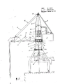
FIG. 1 is a diagrammatic side view of a pneumatic hoist of the present invention;
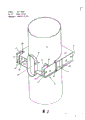
FIG. 2 is an enlarged partial perspective view of a container or receptacle of the pneumatic hoist of FIG. 1 with a connector;
the pneumatic hoist shown in fig. 1 mainly includes: a portal frame 1 movable along the quay bank, a cylindrical tower 3 rotatably mounted on the portal frame by means of a spherical swivel joint 2, a bracket 5 with a suction pipe 6 rotatably hinged to one side of the cylindrical tower and a machine room 7 hinged to the other side of the tower and serving at the same time as a balancing function.
The tower 3 mainly comprises: a container 3 for temporarily receiving granular material fed through a suction pipe 6 and an extension 9 projecting vertically upwards and having a conical shape, to the upper side of which are introduced traction members 10 of a carriage 5 and tensioning members 11 of a machine room 7 in the form of an image-like carriage. The traction element 10 of the carriage 5 consists of a wire rope 12 which is led in a pulley block to a winch (not shown in the figure) located in the machine room 7 via a pulley support 13 at the top of the tower 3, i.e. on the extension 9, and a pulley support 14 on the carriage 5 to a diverting pulley 15 mounted on the machine room 7. A wire rope is also used as a tension member 11 for the machine room 7, which tension member is fastened to the end of the extension member 9 on the one hand and to the machine room 7 on the other hand and keeps the machine room in a horizontal position.
The central part of the tower 3 is a container 8 which is under negative pressure during operation, and its upper cover plate 8.1 and the conventional filter device 8.2 and the discharge funnel 8.3 for the material, as well as the down pipe 8.4 connected behind the discharge funnel are shown in broken lines, the negative pressure required for pneumatic transfer through the suction pipe 6 being generated by a suction fan (not shown) installed in the machine room 7, which suction fan is connected to the upper part of the container 8 through a conduit 16. Dust and small-particle dirt in the material is filtered off in the filter device 8.2, and the conveyed material is passed in a continuous flow through the discharge funnel 8.3 and the down pipe 8.4 to the blade wheel gate 17, which is intended to prevent air from leaking into the container 8, from where it passes through the discharge connection to the conveyor 18 and is fed via the discharge chute 19 into a discharge vehicle, such as a container of a truck or train.
As can be seen from the general structure of fig. 1, in the connecting element 4 there are hinge points 20, 21 of the bracket 5 and the machine room 7, which are in the same horizontal plane, so that all the horizontal resultant forces generated by the bracket 5 and the machine room 7 are balanced with each other in this plane, i.e. in the connecting element 4. Furthermore, since the traction means 10 of the carriage 5 and the tensioning means 11 of the machine room 7 pass through the top of the tower 3, the vertical forces generated here are transmitted uniformly through the conical extension 9 to the wall of the container 8 and, together with the vertical forces acting on the hinge points 20, 21 of the connecting element 4, act on the spherical rotary joint 2 and thus on the gantry 1 through the lower container wall part which is no longer under negative pressure.
The connecting element is shown separately in fig. 2, the structural design of which has to be such that the carrier 5 can be raised and lowered over a wide range, while the machine room essentially only stays in a horizontal position. The hinge point 20 of the bracket 5 and the hinge point 21 of the machine room 7 are thus not of the same construction. In addition, the hinge construction of the console 5 and the machine room 7 is of secondary importance in the context of the present application, so that a relatively simple form of hinge openings 5.1, 7.1 can be used as shown in fig. 1, while two arms with hinge openings each project from the console and the machine room, and the hinge can be designed to be detachable for ease of assembly.
The connecting element 4 is mainly formed by two rectangular plates 22, 23 having apertures for the containers 8 and webs 24, 25, 26 welded between the two plates. The rectangular plates are welded together along the walls passing through the holes and the container 8, the upper plate 22 being partly broken away in the front corner of the figure. In order to form the hinge points 20 of the support, here simplified as holes for receiving supporting bolts, two outer webs 24 and two inner webs 25 are welded between the plates 22, 23, wherein one outer web 24 and one inner web 25 are provided for each hinge hole 20. In order to allow the bracket 5, not shown in fig. 2, to rotate freely up and down over a large range around the hinge point 20, the plates 22, 23 at the web portions 24, 25 are slotted 27. The webs 24, 25 and the transverse webs 28 welded to the plate edges and, in the rear, to the vessel wall form a vertical shaft from top to bottom for receiving the ends of the brackets 5. For the hinging of the machine room, the construction of the hinging point 21 is very simple, since no upward and downward rotation is generated. Although a similar solution can be used, for example with an additional inner web 25 on the side of the carrier, in the present case an opening in the web 26 is in principle sufficient. No slots are required in the plates 22, 23 since the machine room is not rotated.
Furthermore, an inlet 29 for the suction tube 6 leading into the connecting piece 4 is provided between the hinge points 20 of the carriers. To this end, the pipe connection 30 is welded to the corresponding notch in the wall of the container 8 along the entire periphery of the notch. Furthermore, the pipe connections are inserted at the edge portions of the plates 22, 23 and are connected to the plates in the through-going position, likewise by welding. The oval shape of the pipe connection ensures that the suction pipe 6 can be moved with the holder 5 in a large range in the vertical direction. In addition to this firm connection of the inlet 29 to the connecting piece 4 via the coupling 30, there are pressure relief openings 31 of this type, which for symmetry and balance reasons should be provided on both sides of the container and closed in the normal state by means of a packing or shutter, which, when a dust explosion or deflagration occurs in the container, ensure that the explosion pressure wave energy is transmitted to the atmosphere after removal of the packing and opening of the shutter, thereby avoiding serious damage to the container. In order to provide a stable frame for the pressure relief opening, it is advantageous if the plates 22, 23 of the connecting element 4 form part of this frame.
The pressure relief openings 31 in the container wall are closed at the top and bottom by the edge regions of the plates 22, 23, so that the pressure relief openings are reinforced, the sides of the openings 31 being framed by connecting webs 32, which are welded to the wall of the container 8 and to the plates 22, 23 and are reliably isolated from the surroundings by means of the webs. Furthermore, each connecting web is also fixed, preferably welded, to the web adjacent to it, whereby the connecting web has an additional very reliable fixing in the event of a dust explosion or deflagration. Of course, the connection between the connecting web 32 and the adjacent web can take a variety of different forms. In the illustrated embodiment, the outer web 24 extends to the front connecting web 32. And web 26 extends to the rear connecting web. A very simple construction is thereby obtained.
In addition, for example in large plants, the construction of the connecting element 4 can also be carried out with more than two plates 22, 23 and correspondingly with an increase in the number of webs 24, 25, 26 and diaphragms 28, changing their position and adapting the position of the hinge points 20, 21 to be arranged.
In addition, in small installations the connecting element is preferably formed by a container section which is thickened compared to the typical wall thickness of the container 8. At the same time as webs are welded to the container section in order to provide the hinge points 20, 21, the inlet 31 of the suction tube and the edge portions of the pressure relief opening 31 essentially do not have to be particularly thickened because of the large wall thickness.
Symbol table
1. Portal frame
2. Spherical rotary joint
3. Tower with a tower body
4. Connecting piece
5. Bracket
5.1 hinge hole
6. Suction tube
7. Machine room
7.1 hinge hole
8. Container with a lid
8.1 cover plate
8.2 Filter device
8.3 discharge funnel
8.4 blanking pipe
9. Extension piece
10. Traction element
11. Tensioning member
12. Steel wire rope
13. Pulley support
14. Pulley support
15. Steering wheel
16. Catheter tube
17. Impeller gate
18. Conveyor
19. Discharge chute
20. Bracket hinge point
21. Machine room hinge point
22. Flat plate
23. Flat plate
24. Web plate
25. Web plate
26. Web plate
27. Trough
28. Diaphragm plate
29. An inlet
30. Pipe joint
31. Pressure relief hole
32. Connecting web
Claims (7)
1. Pneumatic elevator for transporting granular materials, especially for unloading them from ships, having a carrier and a container temporarily containing the granular materials, the carrier with suction pipes being mounted on a support, the carrier being pivotable in a vertical plane and being operated by a traction means, the container being rotatable about its longitudinal axis, preferably cylindrical, the container simultaneously serving as a mounting bracket by means of a force transmission element connected thereto and as a support frame for a machine room counterweighted against the carrier on the other side of the container, characterized in that: the force transmission element is in the form of a connecting element (4) which is located on a vertical section and which surrounds the entire circumference of the vertical section, wherein the pivoting points (20, 21) of the console (5) and the machine room (7) formed on the other side in the form of the console are located in the same horizontal plane, and the traction element (10) of the console (5) and the tensioning element (11) of the machine room (7) are guided to the vertically upwardly extending container (8) extension (9).
2. The pneumatic elevator as claimed in claim 1, wherein: an inlet (29) for a suction pipe (6) is arranged between the bracket (5) and the hinge point (20) of the connecting piece (4), and a pressure relief opening (31) for the container (8) is arranged on each side surface between the hinge point (20) of the bracket (5) and the hinge point (21) of the machine room (7) which are opposite to each other.
3. The pneumatic elevator as claimed in claim 1 or 2, wherein: the connecting element (4) is formed by at least two parallel plates (22, 23) which are provided with through holes for the containers (8) and are welded to the container walls along the holes, the plates are preferably rectangular, and webs (24, 25, 26) for receiving the hinge points of the bracket (5) and the machine room (7) are welded between the plates at the corners.
4. A pneumatic elevator as claimed in claim 3, wherein: for each hinge point (20) of the carrier (5), two webs (24, 25) are provided parallel to one another, and the carrier side of the plates (22, 23) has a slot (27) bounded by the two webs.
5. A pneumatic elevator as claimed in claim 3, wherein: a diaphragm plate (28) is welded to the web (24, 25) at the end opposite the bracket (5), and is also welded to the plates (22, 23) and to the wall of the vessel (8).
6. A pneumatic elevator as claimed in claim 3, wherein: the inlet (29) of the suction pipe (6) is formed as a pipe connector (30) which is inserted into the edge of the plate (22, 23) and welded to the edge and the wall of the container with the corresponding hole, the pipe connector (30) having an oval cross section, the major axis of the oval being oriented in the vertical direction.
7. A pneumatic elevator as claimed in claim 3, wherein: the pressure relief openings (31) of the container (8) are formed by webs (32) which frame corresponding openings in the container wall and are welded to the container wall and to the plates (22, 23), and by edge portions of the plates (22, 23) which cover the webs, each web (32) being at least additionally fixedly connected to an adjacent web (24, 25, 26) having a hinge point (20, 21).
Applications Claiming Priority (2)
| Application Number | Priority Date | Filing Date | Title |
|---|---|---|---|
| DE3522841A DE3522841C1 (en) | 1985-06-26 | 1985-06-26 | Suction lifter |
| DEP3522841.5 | 1985-06-26 |
Publications (2)
| Publication Number | Publication Date |
|---|---|
| CN86104073A CN86104073A (en) | 1986-12-24 |
| CN1004804B true CN1004804B (en) | 1989-07-19 |
Family
ID=6274238
Family Applications (1)
| Application Number | Title | Priority Date | Filing Date |
|---|---|---|---|
| CN86104073.2A Expired CN1004804B (en) | 1985-06-26 | 1986-06-19 | air lift |
Country Status (5)
| Country | Link |
|---|---|
| EP (1) | EP0206094B1 (en) |
| JP (1) | JPH066446B2 (en) |
| CN (1) | CN1004804B (en) |
| AT (1) | ATE39464T1 (en) |
| DE (2) | DE3522841C1 (en) |
Families Citing this family (4)
| Publication number | Priority date | Publication date | Assignee | Title |
|---|---|---|---|---|
| FR2633487B1 (en) * | 1988-07-04 | 1991-04-05 | Tout Pour Le Grain Sa | DEVICE FOR SAMPLING GRANULAR OR POWDERY MATERIALS |
| CN104444450A (en) * | 2014-11-19 | 2015-03-25 | 镇江船舶电器有限责任公司 | Material conveying control table for ship |
| CN106429535B (en) * | 2016-11-30 | 2023-12-19 | 杭州三螺机械设备有限公司 | A spiral negative pressure dual-function ship unloader |
| CN110936312A (en) * | 2019-11-29 | 2020-03-31 | 上海华宜风电模具有限公司 | Integrated web positioning tool |
Family Cites Families (4)
| Publication number | Priority date | Publication date | Assignee | Title |
|---|---|---|---|---|
| BE762913A (en) * | 1971-02-12 | 1971-07-16 | Iniex | VACUUM DEVICE FOR DRAINING BOATS, WAGONS OR ANY OTHER CONTAINER CONTAINING SOLID GRANULAR PRODUCTS. |
| DE2253060B2 (en) * | 1972-10-28 | 1978-09-14 | Buehler-Miag Gmbh, 3300 Braunschweig | Suction cup |
| DE3034465A1 (en) * | 1980-09-12 | 1982-04-29 | PHB Weserhütte AG, 5000 Köln | Portal-mounted ship unloader - has central vertical tube with bottom bend leading to conveyor on quay |
| AU8414482A (en) * | 1981-06-26 | 1983-01-06 | Honeywell Information Systems Incorp. | Terminal connect means |
-
1985
- 1985-06-26 DE DE3522841A patent/DE3522841C1/en not_active Expired
-
1986
- 1986-06-10 AT AT86107887T patent/ATE39464T1/en not_active IP Right Cessation
- 1986-06-10 EP EP86107887A patent/EP0206094B1/en not_active Expired
- 1986-06-10 DE DE8686107887T patent/DE3661523D1/en not_active Expired
- 1986-06-19 CN CN86104073.2A patent/CN1004804B/en not_active Expired
- 1986-06-26 JP JP61148332A patent/JPH066446B2/en not_active Expired - Lifetime
Also Published As
| Publication number | Publication date |
|---|---|
| JPS624137A (en) | 1987-01-10 |
| DE3522841C1 (en) | 1986-09-04 |
| ATE39464T1 (en) | 1989-01-15 |
| DE3661523D1 (en) | 1989-02-02 |
| EP0206094A3 (en) | 1988-01-07 |
| JPH066446B2 (en) | 1994-01-26 |
| EP0206094A2 (en) | 1986-12-30 |
| EP0206094B1 (en) | 1988-12-28 |
| CN86104073A (en) | 1986-12-24 |
Similar Documents
| Publication | Publication Date | Title |
|---|---|---|
| US4546891A (en) | Grappler system for lifting apparatus | |
| GB2050295A (en) | Auxiliary counterweight arrangement for mobile crane | |
| CN1004804B (en) | air lift | |
| US3640413A (en) | Boat crane | |
| CA1189476A (en) | Bulk-material unloading unit for ships or like carriers | |
| CA2243868A1 (en) | Dump block | |
| US4538848A (en) | Grab | |
| CN211895219U (en) | Harbour bulk cargo loads with flexible swift current section of thick bamboo of shipment machine | |
| CN211644369U (en) | Box hoist and mount balance adjustment mechanism | |
| CA1158609A (en) | Dampened fully pivotal hanger for a grapple | |
| CN221140967U (en) | Lifting equipment | |
| CN116002525A (en) | Self-rotating lifting mechanism for tower crane and tower crane | |
| CN111115449B (en) | Box body hoisting balance adjusting mechanism | |
| CN209758884U (en) | Material hoisting device for building | |
| CN211196258U (en) | Foldable large hatch board bolt installation dolly | |
| WO2012030045A1 (en) | Crane for ship | |
| CN214456244U (en) | Side increase-volume grab bucket | |
| CN110789592A (en) | Foldable large hatch board bolt floor truck | |
| CA2267751A1 (en) | Improved crane mechanism | |
| CN206521101U (en) | A kind of swingable loose unpacked material unloading elevator | |
| WO2012030044A1 (en) | Crane for ship | |
| EP0131664A1 (en) | Boom structure | |
| CN221459662U (en) | Glass curtain wall conveying device | |
| CN213356670U (en) | Building material overhead hoist for indoor outer fitment | |
| CN214192356U (en) | Counterweight system for crane and crane |
Legal Events
| Date | Code | Title | Description |
|---|---|---|---|
| C06 | Publication | ||
| PB01 | Publication | ||
| C10 | Entry into substantive examination | ||
| SE01 | Entry into force of request for substantive examination | ||
| C13 | Decision | ||
| GR02 | Examined patent application | ||
| C14 | Grant of patent or utility model | ||
| GR01 | Patent grant | ||
| C19 | Lapse of patent right due to non-payment of the annual fee | ||
| CF01 | Termination of patent right due to non-payment of annual fee |