CN100500103C - Surgical treatment instrument - Google Patents
Surgical treatment instrument Download PDFInfo
- Publication number
- CN100500103C CN100500103C CNB028145194A CN02814519A CN100500103C CN 100500103 C CN100500103 C CN 100500103C CN B028145194 A CNB028145194 A CN B028145194A CN 02814519 A CN02814519 A CN 02814519A CN 100500103 C CN100500103 C CN 100500103C
- Authority
- CN
- China
- Prior art keywords
- tension band
- surgical incision
- fastening member
- surgical
- incision
- Prior art date
- Legal status (The legal status is an assumption and is not a legal conclusion. Google has not performed a legal analysis and makes no representation as to the accuracy of the status listed.)
- Expired - Fee Related
Links
Images














Classifications
-
- A—HUMAN NECESSITIES
- A61—MEDICAL OR VETERINARY SCIENCE; HYGIENE
- A61B—DIAGNOSIS; SURGERY; IDENTIFICATION
- A61B17/00—Surgical instruments, devices or methods
- A61B17/02—Surgical instruments, devices or methods for holding wounds open, e.g. retractors; Tractors
- A61B17/0293—Surgical instruments, devices or methods for holding wounds open, e.g. retractors; Tractors with ring member to support retractor elements
-
- A—HUMAN NECESSITIES
- A61—MEDICAL OR VETERINARY SCIENCE; HYGIENE
- A61B—DIAGNOSIS; SURGERY; IDENTIFICATION
- A61B17/00—Surgical instruments, devices or methods
- A61B17/02—Surgical instruments, devices or methods for holding wounds open, e.g. retractors; Tractors
-
- A—HUMAN NECESSITIES
- A61—MEDICAL OR VETERINARY SCIENCE; HYGIENE
- A61B—DIAGNOSIS; SURGERY; IDENTIFICATION
- A61B17/00—Surgical instruments, devices or methods
- A61B17/34—Trocars; Puncturing needles
- A61B17/3417—Details of tips or shafts, e.g. grooves, expandable, bendable; Multiple coaxial sliding cannulas, e.g. for dilating
- A61B17/3421—Cannulas
- A61B17/3423—Access ports, e.g. toroid shape introducers for instruments or hands
-
- A—HUMAN NECESSITIES
- A61—MEDICAL OR VETERINARY SCIENCE; HYGIENE
- A61B—DIAGNOSIS; SURGERY; IDENTIFICATION
- A61B17/00—Surgical instruments, devices or methods
- A61B17/34—Trocars; Puncturing needles
- A61B17/3462—Trocars; Puncturing needles with means for changing the diameter or the orientation of the entrance port of the cannula, e.g. for use with different-sized instruments, reduction ports, adapter seals
-
- A—HUMAN NECESSITIES
- A61—MEDICAL OR VETERINARY SCIENCE; HYGIENE
- A61B—DIAGNOSIS; SURGERY; IDENTIFICATION
- A61B17/00—Surgical instruments, devices or methods
- A61B17/32—Surgical cutting instruments
- A61B2017/320064—Surgical cutting instruments with tissue or sample retaining means
-
- A—HUMAN NECESSITIES
- A61—MEDICAL OR VETERINARY SCIENCE; HYGIENE
- A61B—DIAGNOSIS; SURGERY; IDENTIFICATION
- A61B17/00—Surgical instruments, devices or methods
- A61B17/34—Trocars; Puncturing needles
- A61B2017/348—Means for supporting the trocar against the body or retaining the trocar inside the body
- A61B2017/3482—Means for supporting the trocar against the body or retaining the trocar inside the body inside
-
- A—HUMAN NECESSITIES
- A61—MEDICAL OR VETERINARY SCIENCE; HYGIENE
- A61B—DIAGNOSIS; SURGERY; IDENTIFICATION
- A61B17/00—Surgical instruments, devices or methods
- A61B17/34—Trocars; Puncturing needles
- A61B2017/348—Means for supporting the trocar against the body or retaining the trocar inside the body
- A61B2017/3492—Means for supporting the trocar against the body or retaining the trocar inside the body against the outside of the body
-
- A—HUMAN NECESSITIES
- A61—MEDICAL OR VETERINARY SCIENCE; HYGIENE
- A61B—DIAGNOSIS; SURGERY; IDENTIFICATION
- A61B90/00—Instruments, implements or accessories specially adapted for surgery or diagnosis and not covered by any of the groups A61B1/00 - A61B50/00, e.g. for luxation treatment or for protecting wound edges
- A61B90/40—Apparatus fixed or close to patients specially adapted for providing an aseptic surgical environment
Landscapes
- Health & Medical Sciences (AREA)
- Life Sciences & Earth Sciences (AREA)
- Surgery (AREA)
- Heart & Thoracic Surgery (AREA)
- Engineering & Computer Science (AREA)
- Biomedical Technology (AREA)
- Nuclear Medicine, Radiotherapy & Molecular Imaging (AREA)
- Medical Informatics (AREA)
- Molecular Biology (AREA)
- Animal Behavior & Ethology (AREA)
- General Health & Medical Sciences (AREA)
- Public Health (AREA)
- Veterinary Medicine (AREA)
- Pathology (AREA)
- Surgical Instruments (AREA)
Abstract
Description
技术领域 technical field
本发明涉及一种用于张开切口的外科处理器械。特别是,本发明涉及一种用在某些情况中的外科处理器械,这些情况包括:在气腹状态下执行处理之后,解除气腹的状态,并将一内部器官从体内取出、且进行处置;以及再次在气腹条件下将器官放回到体内,并确定病变部位,且还辅以其它的处理。The invention relates to a surgical treatment instrument for opening an incision. In particular, the present invention relates to a surgical treatment instrument for use in situations including: after performing a treatment in a pneumoperitoneum state, releasing the pneumoperitoneum state, and removing an internal organ from the body and treating it ; and put the organs back into the body again under pneumoperitoneum conditions and identify the lesion site, and also supplemented by other treatments.
背景技术 Background technique
近些年来,内窥镜外科手术作为一种低创伤的外科手术方法而获得了采用。内窥镜外科手术属于低创伤性的手术,其具有手术住院期短、伤口小的优点。而在手术者方面,则存在一些不足之处,原因在于:手术者要在观察屏幕上投影的图像的同时、用多种镊子等的处理器械进行手术,因而操作将非常困难,且需要更长的时间,从而对手术者造成相当大的压力。尤其是,对胃和大肠执行的手术会耗费很长的时间,且手术者会感到非常紧张。因而,如果预计在执行完内窥镜下的处置之后最终将取出很大的标本,则就需要能有一种外科处理器械,其能容易地闭合小的切口(假如形成的切口较小),从而能很容易地将手术过程从在气腹状态下的处理阶段转换到对经小切口取出到身体表面外的内部器官进行处置的阶段。In recent years, endoscopic surgery has gained adoption as a less invasive surgical procedure. Endoscopic surgery is a low-invasive surgery, which has the advantages of short hospital stay and small wounds. And in terms of the operator, there are some deficiencies, the reason is that the operator will perform the operation with a variety of tweezers and other processing instruments while observing the projected image on the screen, so the operation will be very difficult and it will take a long time to perform the operation. time, thus causing considerable pressure on the operator. In particular, operations performed on the stomach and large intestine take a long time and are very stressful for the operator. Thus, if it is expected that a large specimen will eventually be removed after performing an endoscopic procedure, it is desirable to have a surgical instrument that can easily close a small incision (if the incision is made small), thereby The surgical procedure can be easily transferred from the pneumoperitoneum stage to the stage of internal organs taken out of the body surface through small incisions.
专利文件JP-A-11-160942公开了一种装置,其包括:用于夹住腹壁、并对其进行固定的构件;以及一个圆筒形构件,可通过一简单的机构对位于腹壁钳夹构件之间的间隔距离进行调节,在该调节机构中,事先固定于某一紧固构件上的螺栓等元件被拔出,并被固定到设置在腹膜腔外侧的另一紧固构件上,其中,前一紧固构件被插入到腹膜腔内。对于这种外科处理器械,如果再次形成了气腹状态,则由于设置了两种分别用于在未插入操作器械时、以及插入操作器械时保持气密状态的气密构件,所以在此条件下可经小切口将镊子插入,以便于进行手术。Patent document JP-A-11-160942 discloses a device, which includes: a member for clamping and fixing the abdominal wall; and a cylindrical member that can clamp the abdominal wall by a simple mechanism. The distance between the components is adjusted. In this adjustment mechanism, the bolts and other components previously fixed on a certain fastening component are pulled out and fixed on another fastening component arranged outside the peritoneal cavity. , the former fastening member is inserted into the peritoneal cavity. For this kind of surgical treatment instrument, if the pneumoperitoneum state is formed again, since two kinds of airtight members are respectively used to maintain the airtight state when the operating instrument is not inserted and when the operating instrument is inserted, under this condition Forceps can be inserted through a small incision to facilitate the procedure.
通过采用该装置,可进行这样的手术:在该手术中,在气腹状态下完整地执行了某种处置(该处置例如是切开待取出的内部器官的周围部位)之后,就形成了一个尺寸约为3cm到5cm的小切口,可经该切口将器官取出,且从该小切口将要被进行处理的器官从体内取出,在手术者能直接看到病变部位的情况下,可对病变部位进行切除、摘除和缝合。但是,此技术方案已遇到了一些问题:当利用螺栓来撑开切口时,螺栓会扎陷到围成切口的腹壁部分中,因而常常很难将切口充分地张开;为固定紧固构件的一间隔调节片,要设置一些突出,且间隔调节片被设置在被张开切口的周围,因而,常常难于将器官取出、以对其进行处置。By using this device, it is possible to perform an operation in which, after a certain treatment (for example, an incision around an internal organ to be taken out) is completely performed under the pneumoperitoneum, a A small incision with a size of about 3cm to 5cm, through which the organ can be taken out, and the organ to be treated can be taken out from the body through this small incision, and the lesion can be treated when the surgeon can directly see the lesion. Excision, enucleation, and suturing are performed. However, this technical solution has encountered some problems: when bolts are used to spread the incision, the bolts will sink into the abdominal wall part surrounding the incision, so it is often difficult to fully open the incision; A spacing adjustment piece, some protrusions are provided, and the spacing adjustment piece is arranged around the opened incision, thus, it is often difficult to remove the organ for its disposal.
专利文件JP-A-10-108868公开了一种阀(不论使用那一种镊子,其都可防止气腹的气体从腹膜腔中泄漏出去)、以及带有这种阀的套管针。此阀具有一软质的圆筒构件,其被设置在两个环体之间,通过在相反的方向上分别旋拧这两个环体,就可使不同外径的镊子、以及手术者的手臂插入到阀中,从而可在体内执行处置。通过张开这种阀,可将内部器官从体内取出,并对其进行处置。但是,这种方法具有一个缺点:由于镊子等工具被阀以挤压的方式固定着,所以镊子的前、后移动将是非常困难的。而且除此之外,当手臂插入时,由于手臂的厚度是变化的—尤其是在随着前/后运动的情况下,所以经常难于能保持气密状态,且在此情况下就必须要调节阀的开度。另外,将上述装置固定到腹壁上的作用力只取决于圆筒构件的橡胶弹性,因而装置就具有这样一个问题:其不能灵活地适配腹壁厚度的变化,因而不能将切口充分地张开。Patent document JP-A-10-108868 discloses a valve (which prevents pneumoperitoneum gas from leaking out of the peritoneal cavity regardless of the forceps used), and a trocar with such a valve. This valve has a soft cylindrical member, which is arranged between two rings. By screwing the two rings in opposite directions, tweezers of different outer diameters, and the operator's The arm is inserted into the valve so that the treatment can be performed inside the body. By opening this valve, internal organs can be removed from the body and disposed of. However, this method has a disadvantage: since tools such as tweezers are fixed by the valve in a squeezed manner, it will be very difficult to move the tweezers forward and backward. And on top of that, when the arm is inserted, it is often difficult to maintain an airtight condition due to the varying thickness of the arm—especially with forward/backward movement—and in this case adjustments are necessary. valve opening. In addition, the force for fixing the above-mentioned device to the abdominal wall depends only on the rubber elasticity of the cylindrical member, so the device has a problem that it cannot flexibly adapt to changes in the thickness of the abdominal wall and thus cannot sufficiently open the incision.
第5480410号美国专利公开了一种装置,该装置为柔性封罩件的形式,该封罩件具有一内表面和一开口端。在开口端上设置了用于将该装置固定到腹壁上、并保持气密状态的扩张装置,且设置了至少一个进入孔,以便于能接近封罩件的内部,这样就可以在腹膜腔中、或封罩件的内部进行外科手术。该装置与此前用在腹腔镜手术和胸腔镜手术中的刚性套管针不同,而是用柔软的薄层材料制成的,扩张装置的形状可变形为与腹壁上切口的形状相对应,该扩张装置被从切口中插入,并在腹膜腔中扩张,为了对气腹的二氧化碳气体从腹膜腔流入到封罩件中,从而将该封罩件膨胀开,同时扩张装置则保持了装置与腹壁之间的气密性。在封罩件外周表面上设置有多个检查孔,可将多个镊子插入到封罩件内,并能观察到位于切口下方的部位,且保护了切口的边缘。但是,封罩件的形状基本上是球形的,且当装置被安装好之后,相距设置在外周表面上的各个检查孔的距离就被确定出来了,并保持恒定。因而,如果插入到封罩件中的多个处理器械中的某个器械有很大的移动,则其它的处理器械也会随着该处理器械而移动。另外,相对于镊子等的处理器械,腹壁上切口的尺寸是很大的,而且,在操作过程中,腹壁的任何部分都不会成为处理器械的支点,因而对镊子的操作将是复杂的。除此之外,对切口的张开只取决于薄层板的延展性,因而会遇到这样一个问题:腹壁的厚度可能会阻碍将切口充分地张开。US Patent No. 5480410 discloses a device in the form of a flexible enclosure having an inner surface and an open end. The open end is provided with an expansion device for securing the device to the abdominal wall and maintaining an airtight state, and at least one access hole is provided to facilitate access to the inside of the closure member, so that it can be placed in the peritoneal cavity , or the inside of the enclosure for surgical operations. Unlike the rigid trocars previously used in laparoscopic and thoracoscopic procedures, the device is made of a soft, thin layer of material that deforms to match the shape of an incision made in the abdominal wall. The dilation device is inserted through the incision and expanded in the peritoneal cavity to inflate the closure for pneumoperitoneum carbon dioxide gas to flow from the peritoneal cavity into the enclosure while the dilation device retains the device from the abdominal wall airtightness between them. A plurality of inspection holes are arranged on the outer peripheral surface of the enclosure member, a plurality of tweezers can be inserted into the enclosure member, and the position below the cutout can be observed, and the edge of the cutout is protected. However, the shape of the enclosure member is substantially spherical, and when the device is installed, the distances from the inspection holes provided on the outer peripheral surface are determined and kept constant. Thus, if one of the plurality of treatment instruments inserted into the enclosure moves significantly, the other treatment instruments will also move with the treatment instrument. In addition, compared with processing instruments such as tweezers, the size of the incision on the abdominal wall is very large, and any part of the abdominal wall will not become the fulcrum of the processing instrument during the operation, so the operation of the tweezers will be complicated. In addition, the opening of the incision depends only on the extensibility of the thin-layer plate, so there is a problem that the thickness of the abdominal wall may prevent the opening of the incision sufficiently.
第5640977号美国专利公开一种装置,在该装置中,其结构包括一外套管和两密封装置,该装置经一小切口插入到腹膜腔中,并利用两密封装置而在外套管中形成一气密空间。在该装置中,当手术者的手和手臂经该装置的内部插入到身体内时,就可在气腹的条件下对内部器官进行处置。而且除此之外,如果使用第三个密封装置,则即使手臂被抽出后,仍然能保持身体的气密状态。但是,该装置的结构使得:即使在手术者想将器官从体内取出、以便于对其进行处理时,套管部分仍附着在覆盖着患者身体表面的盖布上。而从被接合部分向外延伸出的那一部分是不能扩张的,因而,除非是切割盖布、以便于能将整个装置一次取出,或者是对套管部分进行切割,否则将不能把器官从体内取出,因而也无法进行处置。如果将装置取出,则就要担心癌变的组织是否会粘附到腹壁上。如果对套管部分进行切割,则在完成了体外的处置之后,将无法重新形成气腹状态,因而将无法完成对腹膜腔内部的观察和处置。U.S. Patent No. 5,640,977 discloses a device in which the structure includes an overtube and two sealing devices. dense space. In this device, internal organs can be treated under pneumoperitoneum when the operator's hand and arm are inserted into the body through the interior of the device. And on top of that, if a third seal is used, the body remains airtight even after the arm is withdrawn. However, the structure of the device is such that even when the operator wants to remove the organ from the body to facilitate its manipulation, the sleeve portion remains attached to the drape covering the surface of the patient's body. The portion extending outward from the engaged portion cannot be expanded, so unless the drape is cut so that the entire device can be removed at one time, or the sleeve portion is cut, the organ cannot be removed from the body. removed and therefore cannot be disposed of. If the device is removed, there is concern about cancerous tissue sticking to the abdominal wall. If the cannula portion is cut, it will not be possible to recreate the pneumoperitoneum state after completion of the extracorporeal treatment, and thus the observation and treatment of the interior of the peritoneal cavity will not be complete.
第5813409号美国专利公开了一种装置(以及其它的装置),在该装置中,套筒与一腹壁固定部分是分开的,并在套筒的远端设置一环体,该环体相对于腹壁固定部分上的另一个环体进行嵌固,由此可将装置固定起来。在该装置中,套筒可与腹壁固定部分分离开,因而能拆下套筒部分,但将腹壁固定部分留在腹壁上,在此条件下,可将器官从体内取出,并对其进行处理。因而,癌变组织将不会粘附到切口上,在对器官的处置完成之后,器官被放回到身体内,并再次固定套筒,从而可在气腹状态下进行观察和处置。但是,很难使套筒的环体与腹壁固定构件在整个圆周上都能嵌固到一起,如果在某些区域处该组装关系是不完全的,则就不能维持气密状态。此外,在该装置中,当通过套筒对镊子等处理器械进行操作时,就会出现这样一个缺陷:由于腹壁上的切口相对于处理器械是很大的,且在操作过程中,腹壁的任何部分都无法作为处理器械的支点,所以对镊子的操作将是非常复杂的。U.S. Patent No. 5,813,409 discloses a device (and other devices) in which the sleeve is separate from an abdominal wall fixation portion and a ring is provided at the distal end of the sleeve, which is opposed to the Another ring on the fixed portion of the abdominal wall is embedded, thereby securing the device. In this device, the sleeve is detachable from the fixed part of the abdominal wall, so that the sleeve part can be removed, but the fixed part of the abdominal wall is left on the abdominal wall, and in this condition, the organ can be removed from the body and processed . Thus, cancerous tissue will not adhere to the incision, and after the treatment of the organ is completed, the organ is placed back into the body and the sleeve is secured again so that observation and treatment can be performed under pneumoperitoneum. However, it is difficult to make the ring body of the sleeve and the abdominal wall fixing member fit together on the entire circumference, and if the assembly relationship is incomplete in some areas, the airtight state cannot be maintained. Furthermore, in this device, when handling instruments such as tweezers are operated through the sleeve, there is a drawback that since the incision on the abdominal wall is large relative to the handling instrument, and during the operation, any part of the abdominal wall Part of it cannot be used as a fulcrum for handling instruments, so the operation of tweezers will be very complicated.
第5366478号美国专利以及JP-A-2000-501978号文件公开了这样的装置:在该装置中,在某一区域处,在身体的外侧和内侧充胀一连续的环体型气圈,从而封闭了一个内部空腔,在插入和拉出手或镊子时,可保持腹膜腔内的气密状态。该装置的结构简单,并易于组装,因而可缩短手术所需的时间。但是,在第5366478号美国专利所公开的装置中,当在解除了气腹状态之后、为了进行处置而将器官从体内取出时,必须要将气圈收缩起来,结果将导致切口会闭合起来,因而出现了一个问题:必须要使用另外一个切口张开器械。在上述的这两种装置中,是沿着圆周方向将气圈充胀起来的,从而会增大装置距离身体表面的高度,因而将器官从体内完全取出将变得困难,且除此之外,这种装置还遇到了这样的问题:镊子等工具不易定位在需要进行处置的部位处。U.S. Patent No. 5,366,478 and JP-A-2000-501978 disclose a device in which a continuous ring-shaped balloon is inflated on the outside and inside of the body at a certain area, thereby closing the An internal cavity is created to keep the peritoneal cavity airtight when inserting and withdrawing hands or forceps. The device has a simple structure and is easy to assemble, thereby shortening the time required for surgery. However, in the device disclosed in U.S. Patent No. 5,366,478, when the organ is taken out of the body for disposal after the pneumoperitoneum is released, the balloon must be contracted, and the incision will be closed as a result. A problem thus arises: it is necessary to use another incision opening instrument. In both of the above-mentioned devices, the balloon is inflated in a circumferential direction, which increases the height of the device from the surface of the body, making it difficult to completely remove the organ from the body, and in addition , This device has also encountered such a problem: tools such as tweezers are not easy to be positioned at the position that needs to handle.
日本专利文件JP-A-11-99156公开了一种装置,在该装置中,一套筒利用一些环状构件而固定到腹壁上,其中的环状构件分别被布置在腹壁的上、下两侧,并设置了两个阀(其中一个为普通的密封阈,另一个阀是用弹性的薄隔膜制成的,且具有一裂缝状的开口),采用这种结构,不论在手已插入、或手尚未插入时,都能提高气密性。在该装置中,如果手和镊子尚未插入,则裂缝状的阀就会在腹膜压力的作用下而按照一定的方式延展,从而使由折叠部分形成的接触表面能相互贴压到一起,由此而保持了气密状态。因而,如果在插入手时使阀张开,则除了弹性薄隔膜的弹性力之外,将不会产生出其它的作用力,因此,对手臂的挤压力将是很小的,在长期使用中,可降低作用在手术者上的压力。但是,这种装置具有一个缺陷:当在解除了气腹状态之后、为了进行治疗处置而将器官从体内取出时,或者在透过切口能直接观察到待处置的病变部位、且对病变部位进行处置时,阀—尤其是裂缝状阀就会成为障碍。此外,在该装置中,当经套管对处理器械进行操作时,会遇到一个问题:由于腹壁上的切口相对于处理器械是很大的,在操作过程中,腹壁的任何部分都无法作为处理器械的支点,所以对镊子的操作将是非常复杂的。Japanese patent document JP-A-11-99156 discloses a device in which a sleeve is fixed to the abdominal wall by means of ring members, wherein the ring members are respectively arranged on the upper and lower sides of the abdominal wall. side, and set two valves (one of which is a common sealing threshold, and the other valve is made of an elastic thin diaphragm, and has a slit-like opening). Or when the hand has not been inserted, the airtightness can be improved. In this device, if the hand and tweezers are not inserted, the slit-shaped valve will be stretched in a certain way under the action of peritoneal pressure, so that the contact surfaces formed by the folded parts can be pressed against each other, thereby while maintaining an airtight state. Therefore, if the valve is opened when the hand is inserted, no other force will be produced except the elastic force of the elastic thin diaphragm, so the extrusion force on the arm will be very small, and it will not be used for a long time. In this way, the pressure on the operator can be reduced. However, this device has a defect: when the organ is taken out of the body for therapeutic treatment after the pneumoperitoneum state is lifted, or the lesion to be treated can be directly observed through the incision and the lesion is treated. Valves—especially cracked valves—can become a hindrance when it comes to disposal. Furthermore, in this device, when the treatment instrument is manipulated through the cannula, a problem is encountered: since the incision in the abdominal wall is large relative to the treatment instrument, no part of the abdominal wall can be used as The fulcrum of the instrument is handled, so the manipulation of the tweezers will be very complicated.
第5741298号美国专利公开了一种装置,在该装置的内侧和外侧设置有一个孔口,该孔口能紧固地夹握住腹壁上位于切口周围的部分,并固定到这些部分上,与该孔口相连接的一盖板将一个内部空腔封闭,从而在插入或拉出镊子时可保持腹膜腔的气密性。该装置结构简单,并易于组装,因而可缩短手术所需的时间。但是,这种装置无法灵活地适配切口尺寸、以及腹壁厚度的变化,因而会出现切口不能被充分张开的问题。U.S. Patent No. 5,741,298 discloses a device in which an orifice is provided on the inside and outside of the device, and the orifice can firmly grip and fix to the parts of the abdominal wall located around the incision, and A cover plate connected to the port closes an internal cavity, thereby maintaining the airtightness of the peritoneal cavity when inserting or withdrawing forceps. The device has a simple structure and is easy to assemble, thereby reducing the time required for surgery. However, this device cannot flexibly adapt to changes in the size of the incision and the thickness of the abdominal wall, and thus there will be a problem that the incision cannot be fully opened.
第5653705号公开了一种装置,在该装置中,一带有螺纹的锥状环形构件被旋入到腹壁中,并固定于此,且该构件上连接有一可拆卸性的柔性包套,当手或镊子被插入和拉出时,可保持腹膜腔内部的气密性。在该装置中,仅通过将环形构件旋拧到一切口中,就能容易地形成检查孔口,且环形构件可作为镊子的操作支点,因而易于对镊子进行操作。但是,由于环形构件被旋拧到切口中,所以会担心切口是否会受到损伤的问题。而且除此之外,还遇到了一个问题:由于为便于旋拧操作而设置有螺纹角,所以会使环形构件变得苯重,另外的一个缺陷是:这种装置无法灵活地适配切口尺寸、以及腹壁厚度的变化,No. 5653705 discloses a device in which a threaded conical ring-shaped member is screwed into the abdominal wall and fixed there, and a detachable flexible sheath is connected to the member. Or the forceps are inserted and pulled out to maintain the airtightness of the inside of the peritoneal cavity. In this device, the inspection aperture can be easily formed only by screwing the ring member into the cutout, and the ring member can be used as an operating fulcrum of the tweezers, thereby facilitating manipulation of the tweezers. However, since the ring member is screwed into the cutout, there is concern about whether the cutout will be damaged. And in addition to this, a problem is encountered: due to the thread angle provided for the screwing operation, it makes the ring member heavy, and another disadvantage is that this device cannot be flexibly adapted to the size of the cutout , and changes in abdominal wall thickness,
发明内容 Contents of the invention
本发明致力于解决上述那些在常规的内窥镜手术中执行处理时所遇到的缺陷,本发明的目的是提供一种外科处理器械,在本发明中,该器械的安置方式能灵活地适配腹壁的各种厚度和切口的各种尺寸,且在将装置安置好之后,能执行将切口张开的第二级操作,从而易于完成切口周围的处置工作,而且在安置装置时,器械距离身体表面的高度是很小的,可很容易地在气腹条件下的处置模式与在腹膜腔外部的处置模式之间进行切换,而且在气腹状态下进行处置的情况中,可对镊子进行操作。The present invention aims to solve the above-mentioned drawbacks encountered when performing treatment in conventional endoscopic surgery. It is suitable for various thicknesses of the abdominal wall and various sizes of incisions, and after the device is placed, it can perform the second-level operation of opening the incision, so that it is easy to complete the treatment around the incision, and when the device is placed, the instrument distance The height of the body surface is small, it is easy to switch between the treatment mode under pneumoperitoneum conditions and the treatment mode outside the peritoneal cavity, and in the case of pneumoperitoneum treatment, the forceps can be adjusted operate.
也就是说,根据本发明,本申请提供了如下的技术方案。That is to say, according to the present invention, the application provides the following technical solutions.
(1)一种外科处理器械,其包括一管状部分,该部分具有一第一紧固构件,其被设置在管状构件近端一侧的开口部分处,管状构件还具有一第二紧固构件,其被设置在该构件远端一侧的开口部分处,其特征在于:在第二紧固构件上安装了至少两条张紧带;且在第一紧固构件上设置了用于调节张紧带的长度、从而对第一紧固构件进行定位的固定装置。(1) A surgical treatment instrument comprising a tubular portion having a first fastening member disposed at an opening portion on the proximal side of the tubular member, the tubular member further having a second fastening member , which is arranged at the opening part of the distal end side of the member, is characterized in that: at least two tension belts are installed on the second fastening member; The length of the strap and thus the fixing means for positioning the first fastening member.
(2)根据上文第(1)段落的外科处理器械,其中,固定装置包括一些张紧带阻力调节构件,这些构件分别被设置在第一紧固构件上制出的一些沟槽中。(2) The surgical instrument according to the above paragraph (1), wherein the fixing device includes some tension band resistance adjusting members, and these members are respectively arranged in some grooves made on the first fastening member.
(3)根据上文第(2)段的外科处理器械,其中,所述的张紧带阻力调节构件包括一狭缝,以便于张紧带能穿过该狭缝作滑动运动,该调节构件还包括用于以气密方式保持着张紧带的装置。(3) The surgical treatment instrument according to paragraph (2) above, wherein the tension band resistance adjustment member includes a slit so that the tension band can slide through the slit, and the adjustment member Also included are means for holding the tension strap in an airtight manner.
(4)根据上文第(3)段的外科处理器械,其中,所述气密保持装置包括制在狭缝附近的不规则结构、以及制在张紧带上的不规则结构。(4) The surgical treatment instrument according to paragraph (3) above, wherein the airtight holding means includes an irregular structure formed near the slit, and an irregular structure formed on the tension band.
(5)根据上文第(4)段的外科处理器械,其中,不规则结构为锯齿形状。(5) The surgical instrument according to paragraph (4) above, wherein the irregular structure is a sawtooth shape.
(6)根据上文第(1)段的外科处理器械,其中,固定装置包括一个设置在第一紧固构件处的止动件、张紧带的一个阻力部分、以及一保持板,这些构件以气密的方式相互接合而保持在一起。(6) The surgical instrument according to the above paragraph (1), wherein the fixing device includes a stopper provided at the first fastening member, a resistance portion of the tension band, and a holding plate, and these members are held together by engaging each other in an airtight manner.
(7)根据上文第(6)段的外科处理器械,其中,气密保持装置包括制在止动件上的不规则结构、以及制在张紧带上的不规则结构。(7) The surgical treatment instrument according to paragraph (6) above, wherein the airtight holding means includes an irregularity formed on the stopper, and an irregularity formed on the tension band.
(8)根据上文第(7)段的外科处理器械,其中,不规则结构为锯齿状。(8) The surgical instrument according to paragraph (7) above, wherein the irregularity is serrated.
(9)根据上文第(1)段到第(8)段之一的外科处理器械,其中,固定装置包括一弹性构件。(9) The surgical instrument according to one of the above paragraphs (1) to (8), wherein the fixing means includes an elastic member.
(10)根据上文第(3)段到第(9)段之一的外科处理器械,其中,气密保持装置包括用于移动张紧带阻力调节构件和张紧带不规则部分二者中之一的装置,以解除张紧带的接合保持状态。(10) The surgical treatment instrument according to any one of the above paragraphs (3) to (9), wherein the airtight holding device includes a resistance adjustment member for moving the tension band and the irregular portion of the tension band. One of the means to release the engagement holding state of the tension belt.
(11)根据上文第(10)段的外科处理器械,其中,用于解除接合保持状态的装置包括一薄片,其可被插入到制在张紧带上的不规则结构、与张紧带阻力调节构件之间,(11) The surgical treatment instrument according to the above paragraph (10), wherein the means for disengaging the holding state comprises a sheet which can be inserted into the irregular structure formed on the tension band, and the tension band Between the resistance adjustment members,
(12)根据上文第(10)段的外科处理器械,其中,用于解除接合保持状态的装置包括一突出部分,其被制在张紧带阻力调节构件与止动件二者中的之一上,其能在解除接合的方向上移动不规则部分。(12) The surgical instrument according to the above paragraph (10), wherein the means for disengaging the holding state includes a protruding portion which is caught in one of the tension band resistance adjusting member and the stopper First, it can move the irregularity in the disengagement direction.
(13)根据上文第(1)段到第(12)段之一的外科处理器械,其中,管状构件和第二紧固构件具有柔性。(13) The surgical instrument according to one of the above paragraphs (1) to (12), wherein the tubular member and the second fastening member have flexibility.
(14)根据上文第(1)段到第(13)段之一的外科处理器械,其中,张紧带的宽度在10mm到60mm之间。(14) The surgical treatment instrument according to one of the above paragraphs (1) to (13), wherein the width of the tension band is between 10 mm and 60 mm.
(15)根据上文第(1)段到第(14)段之一的外科处理器械,其中,张紧带被设计成可被基本水平地拉动。(15) The surgical treatment instrument according to one of the above paragraphs (1) to (14), wherein the tension band is designed to be pulled substantially horizontally.
(16)根据上文第(1)段到第(15)段之一的外科处理器械,其中,一转换器以气密的方式与第一紧固构件组合起来,转换器上安装有一气密的密封构件。(16) The surgical treatment instrument according to any one of the above paragraphs (1) to (15), wherein a converter is combined with the first fastening member in an airtight manner, and an airtight sealing member.
(17)根据上文第(16)段之一的外科处理器械,其中,在转换器上安装有多个气密密封构件。(17) The surgical treatment instrument according to one of the above paragraphs (16), wherein a plurality of hermetic sealing members are mounted on the converter.
(18)根据上文第(16)段之一的外科处理器械,其中,在转换器上安装有一第一气密的密封构件和一第二气密密封构件。(18) The surgical treatment instrument according to one of the above paragraphs (16), wherein a first hermetic sealing member and a second hermetic sealing member are mounted on the converter.
(19)根据上文第(16)段到第(18)段之一的外科处理器械,其中,气密密封构件是一柔性隔膜。(19) The surgical treatment instrument according to one of the above paragraphs (16) to (18), wherein the hermetic sealing member is a flexible diaphragm.
(20)根据上文第(1)段到第(19)段之一的外科处理器械,其中,张紧带阻力调节构件与张紧带二者中至少之一或全部是用纵向弹性模量在0.05kg/mm2到10kg/mm2之间的材料制成的。(20) The surgical treatment instrument according to any one of the above paragraphs (1) to (19), wherein at least one or both of the tension band resistance adjusting member and the tension band are made with longitudinal modulus of elasticity Made of materials between 0.05kg/mm 2 and 10kg/mm 2 .
附图说明 Description of drawings
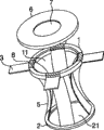
图1A中的轴测图表示了本发明外科处理器械一优选实施方式的外观,图1B中的剖面图表示了外科处理器械的一转换器和一气密密封构件,图1C中的剖面图表示了外科处理器械的管状构件;The axonometric view among Fig. 1 A has represented the appearance of a preferred embodiment of surgical treatment instrument of the present invention, and the sectional view among Fig. 1 B has represented a converter and a hermetic sealing member of surgical treatment instrument, and the sectional view among Fig. 1 C has represented Tubular members of surgical instruments;
图2A中的轴测图表示了本发明外科处理器械另一优选实施方式的外观,图2B中的剖面图表示了器械在被保持在腹壁中时的情形,且在该器械中插入一套管针;The axonometric view in Figure 2A shows the appearance of another preferred embodiment of the surgical treatment instrument of the present invention, and the sectional view in Figure 2B shows the situation of the instrument when it is held in the abdominal wall and a cannula is inserted in the instrument Needle;
图3中的轴测图表示了第一紧固构件的一种示例;An isometric view in Figure 3 shows an example of a first fastening member;
图4A中的剖面图表示了第一紧固构件一种示例方式的沟槽部分,图4B中的剖面图表示了张紧带从一止动件中脱离时的情形;The sectional view among Fig. 4 A has represented the groove part of an exemplary mode of the first fastening member, and the sectional view among Fig. 4 B has represented the situation when the tension band is disengaged from a stopper;
图5中的示意图表示了当本发明的外科处理器械被保持在切口内时的情形;The schematic diagram in Fig. 5 shows the situation when the surgical treatment instrument of the present invention is held in the incision;
图6A表示了根据本发明的外科处理器械中张紧带的一种示例,图6B中的轴测图表示了另一种示例方式,图6C是再一种示例的轴测图;Fig. 6A shows an example of the tension band in the surgical treatment instrument according to the present invention, the axonometric view in Fig. 6B shows another example, and Fig. 6C is an axonometric view of another example;
图7A中的剖面图表示了图6A到图6C所示张紧带上齿条槽的一种示例方式,而图7B中的剖面图则表示了另一种示例方式;The cross-sectional view in Figure 7A shows an example of the rack groove on the tension belt shown in Figures 6A to 6C, and the cross-section in Figure 7B shows another example;
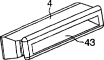
图8A中的轴测图表示了张紧带阻力调节构件的一种示例方式,而图8B则是该构件的剖面图;The axonometric view in Figure 8A shows an example of the tension band resistance adjusting member, while Figure 8B is a cross-sectional view of the member;
图9A中的轴测图表示了通过用在张紧带阻力调节构件中的薄片来解除保持状态的方式,并表示了调节构件与第一紧固构件的关系,图9B中的剖面图表示了当薄片被插入到张紧带阻力调节构件中之前时的情形,图9C中的剖面图表示了薄片在插入后的状态;The axonometric view in Fig. 9A shows the way to release the holding state by the thin sheet used in the tension band resistance adjusting member, and shows the relationship between the adjusting member and the first fastening member, and the sectional view in Fig. 9B shows Before the sheet is inserted into the tension band resistance adjusting member, the cross-sectional view in FIG. 9C shows the state of the sheet after insertion;
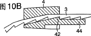
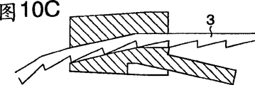
图10A中的轴测图表示了张紧带阻力调节构件的另一种示例,图10B中的剖视图表示了张紧带被插入后的状态,图10C中的剖视图表示了张紧带的脱开状态;The isometric view in Fig. 10A shows another example of the resistance adjusting member of the tension band, the sectional view in Fig. 10B shows the state after the tension band is inserted, and the sectional view in Fig. 10C shows the disengagement of the tension band state;
图11是张紧带阻力调节构件另一种示例的轴测图;Fig. 11 is an axonometric view of another example of a tension band resistance adjusting member;
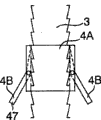
图12中的剖面图表示了张紧带阻力调节构件的另一种示例,该图表示了张紧带的接合状态,图12B是沿垂直于图12A所在纸面的平面剖开而作出的剖面图,图12C中的剖面图表示了张紧带的脱开状态,而图12D则是沿垂直于图12C所在纸面的平面剖开而作出的剖面图;Another example of the tension band resistance adjusting member is shown in a cross-sectional view in Fig. 12, which shows the engaged state of the tension band, and Fig. 12B is a section taken along a plane perpendicular to the plane of the paper where Fig. 12A is located Fig. 12C shows the disengaged state of the tension band, while Fig. 12D is a sectional view taken along a plane perpendicular to the plane of the paper where Fig. 12C is located;
图13A中的轴测图表示了张紧带阻力调节构件的又一种示例,该调节构件是由两个部件组成的,图中表示了这两个部件被组合到一起时的状态,图13B中的轴测图表示了这两个部件相互分离开的状态;The axonometric view in Fig. 13A shows another example of the tension band resistance adjusting member, which is composed of two parts, and the figure shows the state when these two parts are combined together, Fig. 13B The axonometric drawing in shows the two parts separated from each other;
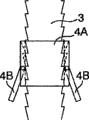
图14A是对张紧带阻力调节构件的再一种示例所作的侧视图,该调节构件是由三个部分组成的,图14B中的俯视图表示了该构件在接合起来时的状态,而图14C中的俯视图则表示了脱开时的状态;Fig. 14A is a side view of another example of the tension band resistance adjusting member, which is composed of three parts, the top view in Fig. 14B shows the state of the members when they are engaged, and Fig. 14C The top view in shows the state when disengaged;
图15A是从上方一侧对保持板的一种示例所作的轴测图,图15B是从下方一侧进行观察所作的轴测图;Fig. 15A is an isometric view of an example of a holding plate viewed from the upper side, and Fig. 15B is an isometric view viewed from the lower side;
图16中的剖面图表示了转换器的一种实施方式;以及The cross-sectional view in Figure 16 shows an embodiment of the converter; and
图17中的剖面图表示了转换器的另一种实施方式。The sectional view in Fig. 17 shows another embodiment of the converter.
具体实施方式 Detailed ways
下面将参照附图对本发明的外科处理器械进行描述。图1A和图1B表示了整个器械的外观。本发明的外科处理器械包括如下的部件。这些部件分别为一第一紧固构件1、一第二紧固构件2、张紧带3、张紧带阻力调节构件(或设置在第一紧固构件上的止动件)4、一管状构件5、一转换器6、以及一气密的密封构件7。The surgical treatment instrument of the present invention will be described below with reference to the accompanying drawings. Figures 1A and 1B show the appearance of the entire device. The surgical treatment instrument of the present invention includes the following components. These components are respectively a
(外科处理器械的结构)(Structure of Surgical Treatment Instruments)
下面对结构作简要的描述,第二紧固构件2具有一用于取出器官的开口部分21,且第二紧固构件2被固定到管状构件5的开口部分21上。管状部分5的另一端与第一紧固部分1相连接。可在第二紧固构件2上设置任意数目的张紧带3。至于用来将张紧带3以气密方式固定到第一紧固构件1上的装置,如图3所示,在第一紧固构件1中制出了一些沟槽、并在各沟槽内装配一保持板8以及一狭缝16,用于使张紧带3能穿过该狭缝来产生滑动运动。作为备选方案,如图1所示,在第一紧固构件1中设置有张紧带阻力调节构件4,并在张紧带阻力调节构件4中制有一狭缝,张紧带3从张紧带阻力调节构件4上的狭缝中穿过。在第一紧固构件1上连接了用于防止气腹气体泄漏的转换器6。在转换器6中基本为中心的部位处设置了气密的密封构件7。管状构件5和张紧带3的长度大于腹壁70的厚度,因而可被安装到任意厚度的腹壁70上,且通过向张紧带3施加拉力而将切口张开。转换器6能被容易地连接到第一紧固构件1上,因而能很容易地在形成气腹状态的模式与取出器官的操作模式之间进行转换。气密的密封构件70被设置在带有窗孔80的转换器6上,因而可放置套管针等工具,并能用镊子的等器具进行处置。Briefly describing the structure, the
(第一紧固构件)(first fastening member)
第一紧固构件1被设置在管状构件5的近端侧开口部分处。通常,该第一紧固构件是用注塑成型方法、压力成型方法或挤出成型方法制成的。第一紧固构件被保持为与管状构件5的表面紧密地接触,并通过熔接或粘接等方法固定到管状构件上,或者是利用O型圈等部件以机械连接的方法固定到管状构件5上。第一紧固构件的形状基本上为圆环形、多边形或其它形状,只要其中央部分具有一用于取出器官的开孔部分,则该构件的形状并不限定于特定的某种形状。手术者的手指和手可插入到该开孔部分中,且优选地是,第一紧固构件的尺寸被设计成:当其被安放到腹部上时,其并不显得沉重。例如,优选地是,第一紧固构件为环形,也就是说,其形状总体上为圆环形,其外径在50mm到300mm之间,而内径则在30mm到280mm之间。优选地是,第一紧固构件的高度要尽可能地低,从而能便于器官经开孔部分11而被拉出到身体表面72上,并在将长柄处理器械插入到体内时,如以开孔部分11作为支点,则能扩大进行处置的范围。优选地是,该高度在5mm到50mm之间。固定装置可具有图3所示的构造,在该结构中,在第一紧固构件1上制有用于将其组装到保持板8上的沟槽,且制出了狭缝16,张紧带3可按照气密的方式滑动地插装到狭缝16中。在此情况下,优选地是,在沟槽部分12中制有用于保持张紧带3的止动件13。如图3、4A和4B所示,止动件13用于防止切口的开度变小,并便于对切口的张开操作,且缓解了作用在手术者上的压力。作为备选方案,固定装置具有这样的结构:在该结构中,在第一紧固构件1处设置了张紧带阻力调节构件4。尽管张紧带阻力调节构件4可被设置在一个沟槽中,该沟槽被制在第一紧固构件与身体表面接触的表面10中,或者被制在与该表面10相反的一个表面上,但优选地是,在与身体表面接触面10相垂直的、第一紧固构件1的侧面上形成一些空腔,并将张紧带阻力调节构件4分别设置在这些空腔中。采用这种结构,利用一个构件就可形成安装转换器6的表面,且不存在任何的接头部位,从而易于保持装置的气密性。优选地是,在张紧带阻力调节构件4要被固定的那一部分上制出凸肋41,利用这样的结构设计可提高气密性。The
优选地是,第一紧固构件1上设置有用于在水平方向上分别拉紧张紧带3的张紧带阻力调节构件4,从而在将器官从本发明的外科处理器械中拉出、以便于进行处置时,张紧带3不会成为妨碍物。转换器6被组装到第一紧固构件1上。优选地是,第一紧固构件1外边缘的形状被设计成这样的:使得转换器6上的卡爪9能与该外边缘相接合。被拉出的器官与第一紧固构件1的上表面直接保持接触,因而该上表面是平面,从而不会对拉出的器官造成损伤。对于第一紧固构件1的材质,可使用氯乙烯树脂、聚亚氨酯树脂、聚酰胺树脂、聚乙烯树脂、聚丙烯树脂、聚缩醛树脂、ABS(丙烯腈-丁二烯-苯乙烯)树脂、SEBS树脂、硅酮橡胶、或不锈钢等金属。Preferably, the
(第二紧固构件)(second fastening member)
第二紧固构件2被设置在管状构件5的开口部分21处。通常,第二紧固构件是通过注塑成型、压力成型或挤出成型方法制出的。第二紧固构件被管状构件5包围着,且保持与管状构件5的紧密接触,其可通过熔接或粘接方法而固定到管状构件5上,或者可以使管状构件保持与第二紧固构件2的表面紧密接触,并利用熔接或粘接方法而固定到第二紧固构件2上。作为备选方案,也可通过采用O型圈等构件的机械紧固方法来进行固定。在借助于腹腔内窥镜对大肠进行切除的情况下,优选地是,对于尺寸约为20mm到80mm的小切口,内径被设定为约30mm到120mm,而外径被设定为约40mm到200mm。希望装置在腹膜腔中并不显得沉重,因而,第二紧固构件的厚度优选为约0.5mm到10mm。由于环体是以折弯的状态、经切口插入到腹膜腔中的,所以优选地是,其材料具有一定程度的弹性。对于第二紧固构件2的材质,可使用氯乙烯树脂、聚亚氨酯树脂、聚酰胺树脂、聚乙烯树脂、聚丙烯树脂、聚缩醛树脂、ABS(丙烯腈-丁二烯-苯乙烯)树脂、SEBS树脂、硅酮橡胶、或不锈钢等金属。The
(张紧带)(tension belt)
如图1A和图2B所示,张紧带3被连接到第二紧固构件2上,并穿过由第一紧固构件1和保持板8形成的各个狭缝16、以及张紧带阻力调节构件4的各个狭缝43。如图5所示,切口被扩张开(尽可能变为接近于圆形的形状),因而优选地是:张紧带3的宽度不小于10mm,如果其宽度过大,则就难于将装置插入到切口中,宽度的优选范围在10mm到60mm之间。优选地是,张紧带为薄片的形式,其厚度在0.1mm到0.5mm之间,从而能将装置距离身体表面的高度保持在较低的数值上。优选地是,张紧带3的长度是很大的,从而能适配各种壁厚,但如果其长度太大,则张紧带会暴露到身体表面上,从而限制了套管针60等工具上穿刺部分的运动。因而,优选地是,张紧带的实际长度为30mm到200mm。在张紧带3上设置一阻力部分31,由此使被扩张开的切口的尺寸不会减小。阻力部分31只需要能对张紧带3沿狭槽43的滑动提供阻力就可以了,可仅在张紧带上制出突起、孔洞等不规则结构42,但优选地是如图6所示那样在张紧带上制出锯齿状的棘牙槽32。棘牙槽的深度被设定为约0.5mm到2.5mm,以便于能减小张紧带3的厚度。如图6A到图6C所示,可在张紧带3的部分段上制有棘牙槽32。如果如图7A和图7B所示那样,将棘牙槽32的角度设计成锐角,则就能降低张开切口时的所产生的阻力,而这样的效果是所希望的。可将棘牙槽32制在张紧带的侧面上,但优选地是如图1A到图1C所示那样:将棘牙槽制在张紧带背向开孔部分21的那一面上,从而在将器官拉出时,器官不会与张紧带的棘牙槽发生接触,因而不会被刮伤。优选地是,该材料具有适度的柔性,并具有良好的滑动特性。为了便于平滑地进行操作,张紧带3最好具有适当的硬度(肖氏硬度约为A40到D60),从而使张紧带的整体或部分(带有不规则结构的部分)能被变形。张紧带是用无纺布或纺织薄层材料制成的,或者是通过挤出成型、注塑成型或压力成型的方法来制成,所用的材料并无特定的限制。可使用聚酰胺树脂、氯乙烯树脂、聚亚氨酯树脂、聚乙烯树脂、聚丙烯树脂、或聚缩醛树脂。由于带有树脂丝网或金属丝网的薄板不易于发生变形,所以这种薄板也是优选的。As shown in Figure 1A and Figure 2B, the
(张紧带阻力调节构件)(Tension belt resistance adjustment member)
如图1C所示,张紧带阻力调节构件4被设置在第一紧固构件1上。如图8A和图8B所示,张紧带阻力调节构件4具有便于张紧带3穿过的狭缝43。优选地是,狭缝43的横截面形状基本上与张紧带3的形状相同,从而可确保气密性。As shown in FIG. 1C , the tension band
在靠近狭缝43的位置处,制有与张紧带3的不规则结构相对应的不规则结构42,从而可防止张紧带3在使已张开切口发生收缩的方向上移动。At a position close to the
优选的是,在张紧带阻力调节构件4上设置有凸肋41或凹陷部分,以便于在该构件4被安装到第一紧固构件1上时能保持气密状态。在图8A和图8B中表示了一种示例。Preferably, a
为了使切口能在张开状态和闭缩状态之间适当地进行转换,优选地是:设置一用于解除张紧带3被保持着的状态的装置。例如,如图9A到图9C所示,通过在张紧带3与张紧带阻力调节构件4的不规则结构42之间插入一薄片90,就可解除不规则结构42的接合保持状态。薄片90可被设置成一单独的构件,或者可被固定到第一紧固构件1上,从而可相对于第一紧固构件1滑动。如图10A到图10C、以及图11所示,为了使张紧带阻力调节构件4的不规则结构42能在某一方向上移动、从而解除保持状态,可在不规则部分上制出一突出部分44,且该突出部分从不规则部分延伸出,在此情况下,可对突出部分进行操作来使不规则部分42产生移动。如图10A和图10B所示,为了使不规则结构42能可靠地产生移动,优选地是在张紧带阻力调节构件4的一些部分上制出一些凹口45,这些凹口分别被设置在靠近不规则结构42相对两端的位置处。如图11所示,该结构包括两个部件,当带有不规则结构42的那个部件的突出部分44被牵拉时,此部件就会沿设置在另一部件上的导轨向下移动。因而就能使带有不规则结构42的部件产生移动,从而解除被保持着的状态。如图12A到图12D所示,张紧带阻力调节构件4可被分成两个部件4A和4B,在当前情况下,在带有不规则结构的部件4B的下侧设置了一弹簧46,从而可使不规则结构进行上下移动。如图13A和图13B所示,可设置这样一种结构:在该结构设计中,张紧带阻力调节构件4可被分成两个部件4A和4B,且可在水平方向上对不规则结构进行抽拉。如图14A到图14C所示,张紧带阻力调节构件4也可被分成三个部件4A、4B和4C,在此情况下,可利用不规则的操作部分而将不规则部分张开、或使其移动。张紧带阻力调节构件4的内部可被制成一个空腔,在此情况下,通过将该空腔内的压力降低就能解除被保持着的状态。In order to enable the incision to be properly switched between the open state and the closed state, it is preferable to provide a means for releasing the state in which the
用于阻止已张开切口发生收缩的不规则结构被制在张紧带3上,因而,当张开切口时,就会产生出阻力,为了能平顺地进行操作,优选地是:张紧带阻力调节构件4具有适当的硬度(肖氏硬度约为A40到D60),从而使整个构件或部分构件(带有不规则结构的部分)是可进行变形的。对于其中所用的材料,可采用氯乙烯树脂、聚亚氨酯树脂、聚酰胺树脂、聚乙烯树脂、聚丙烯树脂、聚缩醛树脂、ABS(丙烯腈-丁二烯-苯乙烯)树脂、SEBS树脂、或硅酮橡胶。The irregular structure used to prevent the contraction of the opened incision is made on the
如图3、4A和图4B所示,每一保持板8都被装配到第一紧固构件1上,并形成了狭缝16,张紧带3可在该狭缝中滑动。对其具体形状并无太大的限定,但优选地是:保持板带有杆轴81,杆轴81被布置在靠近保持板中央轴线的位置处,并被安装到第一紧固构件7中;保持板还带有一张紧带保持部分83,其保持着张紧带3,而杆轴81则被作为支轴,并保持与张紧带的紧密接触;保持板还带有侧腿82,其可施加作用力,用于将张紧带保持部分83紧压到张紧带3上。用于固定张紧带3的装置包括(制在第一紧固构件1上的)不规则结构13,其用于保持着与张紧带3的接合状态,因而,在使用保持板8的情况下,可应用与上述机构类似的机构,以便于解除被保持着的状态。对于制造保持板8的材料,可使用氯乙烯树脂、聚亚氨酯树脂、聚酰胺树脂、聚乙烯树脂、聚丙烯树脂、聚缩醛树脂、ABS树脂、聚碳酸酯树脂、硅酮橡胶、碳氟化合物树脂或不锈钢等金属。As shown in FIGS. 3 , 4A and 4B , each retaining
(管状构件)(tubular member)
管状构件5为直管形状或基本为锥管状,且壁厚为0.05mm到3mm。同时,该管状构件是通过膨胀成型等方法制成的,但对制造方法并无特定的限制。管状构件5的尺寸是可变的,这取决于要被处置的部位、以及具体的目的,但在借助于腹腔内窥镜对大肠执行切除的情况中,其外径优选为30mm到300mm。在使用过程中,内窥镜和镊子等的处理器械要被频繁地插入和拉出,因而希望能选出某种材料类型,其不会太沉重,又具有适度的柔性,且当这些处理器械被撞到该管状构件时,其不会被划坏或磨损。例如,优选地是,可采用软质的氯乙烯树脂、聚亚氨酯树脂、聚乙烯树脂、聚酰胺树脂、聚丙烯树脂、聚酯树脂、SEBS树脂、硅酮橡胶、或天然橡胶作为该材料。The
(转换器)(converter)
转换器6被安装到第一紧固构件1上,并用于在气腹的条件下保持腹膜腔内部的气密。为了联接和拆卸转换器,可通过凸面或凹面部分或螺钉将转换器固定到第一紧固构件1上,但优选而方便的作法是:在转换器6的边缘上设置卡爪9,在此情况下,卡爪与第一紧固构件1的侧面安装地接合起来。通常,转换器是用注塑成型或压力成型方法制成的。对于某种类型的转换器6,如图1A、1B和图16所示,在该转换器6上固定了气密的密封构件7,该构件是不带有孔洞的隔膜,处理器械可穿刺过该气密密封构件。对于另一类型的转换器,如图17所示,气密密封构件被分成了两部分72和74,且第一气密密封构件72和第二气密密封构件74被固定到转换器上。在转换器的中央部位处制有窗孔80,气密的密封构件7由该窗孔而外露。窗孔80的尺寸由要被插入的处理器械的尺寸确定,可将窗孔的尺寸合适地设定在1mm到80mm之间。其高度可被适当地确定在1mm到40mm之间,从而可防止与处置动作出现干涉。对于所涉及的材质,可使用刚性的树脂,例如氯乙烯树脂、聚亚氨酯树脂、聚乙烯树脂、聚丙烯树脂、聚缩醛树脂、聚碳酸酯、聚砜树脂、硅酮橡胶、天然橡胶、或NBR等的人造橡胶。The
(气密密封构件)(airtight sealing member)
设置气密密封构件7是为了在套管针60或镊子被插入时能保持气密状态。该构件是一块不带有任何孔洞的隔膜。优选地是,其厚度在0.1mm到3mm之间。如果厚度小于0.1mm,则该阀易于在二氧化碳气体的压力作用下发生变形,且如果厚度大于3mm,则在插入镊子等的处理器械时,所产生的摩擦阻力就会增大,结果将导致插入困难。优选地是,考虑到处理器械或其它结构的外径,该密封构件的内径被设定为0.5mm到80mm。优选地是,该气密密封构件是用这样一种材料制成的:其撕裂强度在5N/mm到100N/mm之间,从而当套管针60等的处理器械被插入时,可保持气密的状态。另外,更为优选地是该材料具有柔性,合适的材料例如是天然橡胶、硅酮橡胶、氯乙烯树脂、尿烷树脂或SEBS树脂。The
(第一气密密封构件)(first hermetic sealing member)
设置第一气密密封构件72是为了在镊子等器械未被插入时保持气密状态。可用一杯帽等结构体来封闭近端一侧的顶端,或者可在内部设置一个瓣阀和鸭嘴阀等的阀件。此处,可采用这样一种类型:在此类构件中,在撕裂强度很高(20kgf/cm到50kgf/cm)的硅酮橡胶(弹性材料)隔膜中,只制有一条狭缝。在利用杯帽等结构体来封闭端部的情况下,可在近端一侧的入口处设置了一固定构件,在此情况下,杯帽利用凸面—凹面的配合关系而相对于该固定构件安装,或者可利用一螺钉将杯帽固定着。通常,所述杯帽是通过注塑成型方法形成的,而对于其中的材料,可采用略显刚性的树脂制成,例如可采用氯乙烯树脂、聚亚氨酯树脂、聚乙烯树脂、聚丙烯树脂、聚缩醛树脂、聚碳酸酯、聚砜树脂、硅酮橡胶、天然橡胶、或NBR等的人造橡胶。而对于瓣阀的情况,可将一刚性的模制品与一弹簧构件组合使用,其中的模制品被容纳在通常腹腔内窥镜外科手术所用的套管针中。作为备选方案,可使用硅酮橡胶等材料制出的弹性构件,该构件被制成阀瓣形状。瓣阀将不会向身体的外侧开启,但是却可向身体的内侧移动,因而,当处理器械或其它工具未被插入时,瓣叶会被体内的正压力顶向身体的外侧,因而可被关闭。可利用注塑成型或压力成型等方法来制出该瓣阀,而对于其材质,可采用氯乙烯树脂、聚亚氨酯树脂、聚乙烯树脂、聚丙烯树脂、聚缩醛树脂、聚碳酸酯树脂、聚砜树脂、或硅酮橡胶。类似地,可利用注塑成型方法或压缩成型方法来制出鸭嘴形阀,其主要是用硅酮橡胶等弹性材料制成的。The first airtight sealing
(第二气密密封构件)(Second hermetic sealing member)
设置第二气密密封构件74的目的是为了在镊子等器械被插入时能保持气密状态。可设置一带有圆形孔的密封阀或类似装置。可通过注塑成型、压力成型或对一板材进行加工而制出该密封阀,并用熔接或粘接的方法固定到近端一侧的入口或转换器6上。优选地是,密封阀的厚度在0.1mm到3mm之间。如果厚度小于0.1mm,则该阀易于在二氧化碳气体的压力作用下发生变形,且如果厚度大于3mm,则在插入镊子等的处理器械时,所产生的摩擦阻力就会增大,结果将导致插入困难。优选地是,考虑到处理器械或其它构件的外径,阀的内径可被设定在0.5mm到30mm之间。优选地是,密封阀是用柔性材料制成的,合适的材料例如是天然橡胶、硅酮橡胶、氯乙烯树脂、尿烷树脂或SEBS树脂。The purpose of providing the second airtight sealing
(使用方法)(Instructions)
下面,将对根据本发明的外科处理器械的实际使用方法进行描述。为了借助于腹腔内窥镜来对大肠进行切除,首先,要将多根套管针60插入到腹部中,并在该部位中形成一个尺寸约为3cm到5cm的小切口,估计器官可被从该切口拉出。将第二紧固构件2插入到该小切口中,然后牵拉张紧带3以张开切口。Next, the actual usage method of the surgical treatment instrument according to the present invention will be described. In order to resect the large intestine by means of a laparoscope, first, a plurality of
然后,如图2所示,以气密的方式将转换器6固定到第一紧固构件1上。并使套管针60和其它工具刺穿转换器6的气密密封构件7,经该密封构件而插入腹腔内窥镜和处理器械,从而可在腹腔内窥镜下进行处置,该处置操作例如是切断大肠、切除淋巴节、以及对血管的处理,而且在完成了足够的操作之后,将转换器6拆去,从而将大肠从体内拉出,并在能直接进行观察的条件下对大肠上病变部位附近的部分执行切除、缝合等操作,然后再将大肠放回到体内,然后,将转换器6重新联接到第一紧固构件1上,并再次形成气腹状态,此条件下能清楚地观察到腹膜腔的内部。如果需要执行另一项处理,且该处理工作需要在气腹状态下进行,或者需要解除气腹状态,则就可将转换器6拆去,然后再执行此项处理。如果在处理过程中,需要放松张紧带,则可利用解除装置来实现这一效果。Then, as shown in FIG. 2 , the
对于本发明的外科处理器械,仅通过拆卸掉转换器6就可容易地在两种模式之间进行转换,这两种模式即为:在气腹状态下进行处置、以及在腹膜腔的外部进行处置。在转换器6上设置气密的密封构件7,因而当在气腹条件下执行处置时,可经过本发明的产品而插入套管针,从而能对镊子进行操作。在取出癌变部位时,腹壁上的切口受到管状构件5的保护,因而不必担心切口会受到癌细胞的感染。可按照这样的方式来固定该装置:使得利用张紧带3上的棘齿机构就能向切口施加足够的张力,且切口的开度不会缩小。如果需要放松张紧带,则通过用于解除接合保持的装置就能释放张紧带。With the surgical treatment instrument of the present invention, it is easy to switch between two modes, namely: treatment in the pneumoperitoneum state, and treatment outside the peritoneal cavity, simply by detaching the
在腹腔内窥镜手术过程中,能容易地在气腹状态下的处置模式与在腹膜腔外部进行处置的模式之间进行转换,且在直接可见的情况下,能容易地对切口下方的部位进行处置,因而缓解了对手术者的压力,并能缩短手术所需的时间,且除此之外,相比于腹腔切开手术,这种手术所形成的切口很小,对患者的负担也更小,因而可缩短患者在手术后的住院期,这样,对患者和医院都是有利的。另外,手术后切口的疤痕也是很小的,以致于很不明显,因而,从美观的角度考虑,本发明也是有效的。Easily switch between pneumoperitoneum and outside of the peritoneal cavity during laparoscopic surgery and allow easy access to the area below the incision with direct visualization The pressure on the operator is relieved and the time required for the operation can be shortened. In addition, compared with laparotomy, the incision formed by this operation is small, and the burden on the patient is also lower. Smaller, thus shortening the patient's post-operative hospital stay, which is beneficial to both the patient and the hospital. In addition, the scar of the incision after the operation is so small that it is not obvious, so the present invention is also effective from an aesthetic point of view.
上述的本发明外科处理器械不仅减轻了对手术者的压力,而且由于相比于腹腔切开手术能使切口的疤痕变得更小,所以还能减轻患者的负担,因而,本发明的器械对患者和医院都是有利的。The above-mentioned surgical treatment instrument of the present invention not only reduces the pressure on the operator, but also reduces the burden on the patient because the scar of the incision can be made smaller compared with laparotomy. Both patients and hospitals benefit.
Claims (15)
Applications Claiming Priority (4)
| Application Number | Priority Date | Filing Date | Title |
|---|---|---|---|
| JP2001218851A JP2002325769A (en) | 2000-07-18 | 2001-07-18 | Medical treatment tools |
| JP218851/2001 | 2001-07-18 | ||
| JP337264/2001 | 2001-11-02 | ||
| JP2001337264 | 2001-11-02 |
Publications (2)
| Publication Number | Publication Date |
|---|---|
| CN1533258A CN1533258A (en) | 2004-09-29 |
| CN100500103C true CN100500103C (en) | 2009-06-17 |
Family
ID=26618965
Family Applications (1)
| Application Number | Title | Priority Date | Filing Date |
|---|---|---|---|
| CNB028145194A Expired - Fee Related CN100500103C (en) | 2001-07-18 | 2002-07-16 | Surgical treatment instrument |
Country Status (6)
| Country | Link |
|---|---|
| US (1) | US7297106B2 (en) |
| EP (1) | EP1407715B1 (en) |
| KR (1) | KR100813755B1 (en) |
| CN (1) | CN100500103C (en) |
| DE (1) | DE60237823D1 (en) |
| WO (1) | WO2003007821A1 (en) |
Cited By (2)
| Publication number | Priority date | Publication date | Assignee | Title |
|---|---|---|---|---|
| CN106236163A (en) * | 2016-09-07 | 2016-12-21 | 江苏芸迪医疗科技发展有限公司 | Adjustable for surgical operation and fixed lens skin incision retracts dilator |
| CN107661131A (en) * | 2017-08-22 | 2018-02-06 | 佛山市优特医疗科技有限公司 | A kind of surgical incision retractor |
Families Citing this family (101)
| Publication number | Priority date | Publication date | Assignee | Title |
|---|---|---|---|---|
| US7537564B2 (en) | 1998-12-01 | 2009-05-26 | Atropos Limited | Wound retractor device |
| US7559893B2 (en) | 1998-12-01 | 2009-07-14 | Atropos Limited | Wound retractor device |
| IE20000835A1 (en) | 1999-10-14 | 2002-02-06 | Atropos Ltd | A retractor |
| WO2002034108A2 (en) | 2000-10-19 | 2002-05-02 | Applied Medical Resources Corporation | Surgical access apparatus and method |
| EP2422829B1 (en) | 2001-08-14 | 2013-03-06 | Applied Medical Resources Corporation | Surgical access sealing apparatus |
| US6958037B2 (en) | 2001-10-20 | 2005-10-25 | Applied Medical Resources Corporation | Wound retraction apparatus and method |
| EP1441648B9 (en) * | 2001-10-20 | 2012-04-25 | Applied Medical Resources Corporation | Wound retraction apparatus |
| CA2488118C (en) | 2002-06-05 | 2012-01-10 | Applied Medical Resources Corporation | Wound retractor |
| US9271753B2 (en) | 2002-08-08 | 2016-03-01 | Atropos Limited | Surgical device |
| AU2003273510A1 (en) | 2002-09-19 | 2004-04-08 | Atropos Limited | A wound retractor system |
| US20050020884A1 (en) | 2003-02-25 | 2005-01-27 | Hart Charles C. | Surgical access system |
| US7811274B2 (en) | 2003-05-07 | 2010-10-12 | Portaero, Inc. | Method for treating chronic obstructive pulmonary disease |
| US7426929B2 (en) | 2003-05-20 | 2008-09-23 | Portaero, Inc. | Intra/extra-thoracic collateral ventilation bypass system and method |
| US7533667B2 (en) | 2003-05-29 | 2009-05-19 | Portaero, Inc. | Methods and devices to assist pulmonary decompression |
| US7252086B2 (en) | 2003-06-03 | 2007-08-07 | Cordis Corporation | Lung reduction system |
| US7377278B2 (en) | 2003-06-05 | 2008-05-27 | Portaero, Inc. | Intra-thoracic collateral ventilation bypass system and method |
| EP1834596A3 (en) * | 2003-07-15 | 2007-09-26 | Respira, Inc. | Methods and devices to accelerate wound healing in thoracic anastomosis applications |
| US7682332B2 (en) | 2003-07-15 | 2010-03-23 | Portaero, Inc. | Methods to accelerate wound healing in thoracic anastomosis applications |
| JP2007516860A (en) | 2003-08-06 | 2007-06-28 | アプライド メディカル リソーシーズ コーポレイション | Non-adhesive surgical instrument with gel and manufacturing method |
| US7163510B2 (en) | 2003-09-17 | 2007-01-16 | Applied Medical Resources Corporation | Surgical instrument access device |
| WO2005097234A2 (en) * | 2004-04-05 | 2005-10-20 | Tyco Healthcare Group Lp | Surgical hand access apparatus |
| EP2260777A1 (en) * | 2004-10-11 | 2010-12-15 | Atropos Limited | An instrument access device |
| US7398782B2 (en) | 2004-11-19 | 2008-07-15 | Portaero, Inc. | Method for pulmonary drug delivery |
| US8220460B2 (en) | 2004-11-19 | 2012-07-17 | Portaero, Inc. | Evacuation device and method for creating a localized pleurodesis |
| US7824366B2 (en) | 2004-12-10 | 2010-11-02 | Portaero, Inc. | Collateral ventilation device with chest tube/evacuation features and method |
| CN100577112C (en) * | 2005-01-14 | 2010-01-06 | 奥林巴斯医疗株式会社 | surgical treatment instrument |
| WO2007010511A1 (en) | 2005-07-15 | 2007-01-25 | Atropos Limited | A wound retractor |
| US8104474B2 (en) | 2005-08-23 | 2012-01-31 | Portaero, Inc. | Collateral ventilation bypass system with retention features |
| EP1933732B1 (en) | 2005-10-14 | 2009-12-02 | Applied Medical Resources Corporation | Wound retractor with gel cap |
| US7406963B2 (en) | 2006-01-17 | 2008-08-05 | Portaero, Inc. | Variable resistance pulmonary ventilation bypass valve and method |
| US8960194B2 (en) * | 2006-02-23 | 2015-02-24 | Spacelabs Healthcare Llc | Ventilator for rapid response to respiratory disease conditions |
| US8251900B2 (en) * | 2009-03-06 | 2012-08-28 | Ethicon Endo-Surgery, Inc. | Surgical access devices and methods providing seal movement in predefined paths |
| US8821391B2 (en) * | 2009-03-06 | 2014-09-02 | Ethicon Endo-Surgery, Inc. | Methods and devices for providing access into a body cavity |
| US8357085B2 (en) * | 2009-03-31 | 2013-01-22 | Ethicon Endo-Surgery, Inc. | Devices and methods for providing access into a body cavity |
| US8926506B2 (en) * | 2009-03-06 | 2015-01-06 | Ethicon Endo-Surgery, Inc. | Methods and devices for providing access into a body cavity |
| US20080011307A1 (en) * | 2006-07-12 | 2008-01-17 | Beckman Andrew T | Hand assisted laparoscopic device |
| US7749161B2 (en) | 2006-12-01 | 2010-07-06 | Ethicon Endo-Surgery, Inc. | Hand assisted laparoscopic device |
| US7678046B2 (en) * | 2007-03-06 | 2010-03-16 | Ethicon Endo-Surgery, Inc. | Hand assisted laparoscopic seal assembly with a ratchet mechanism |
| US7922656B2 (en) * | 2007-04-04 | 2011-04-12 | Ethicon Endo-Surgery, Inc. | Hand assisted laparoscopic seal assembly with detachable attachment ring |
| ES2623049T3 (en) | 2007-05-11 | 2017-07-10 | Applied Medical Resources Corporation | Surgical retractor |
| EP2146643A4 (en) | 2007-05-11 | 2012-05-30 | Applied Med Resources | Surgical retractor with gel pad |
| US7931641B2 (en) | 2007-05-11 | 2011-04-26 | Portaero, Inc. | Visceral pleura ring connector |
| US8163034B2 (en) | 2007-05-11 | 2012-04-24 | Portaero, Inc. | Methods and devices to create a chemically and/or mechanically localized pleurodesis |
| US8062315B2 (en) | 2007-05-17 | 2011-11-22 | Portaero, Inc. | Variable parietal/visceral pleural coupling |
| US8657740B2 (en) | 2007-06-05 | 2014-02-25 | Atropos Limited | Instrument access device |
| US8343047B2 (en) | 2008-01-22 | 2013-01-01 | Applied Medical Resources Corporation | Surgical instrument access device |
| US8336540B2 (en) | 2008-02-19 | 2012-12-25 | Portaero, Inc. | Pneumostoma management device and method for treatment of chronic obstructive pulmonary disease |
| EP2242527A4 (en) | 2008-02-19 | 2011-07-13 | Portaero Inc | DEVICES AND METHODS FOR ADMINISTERING A THERAPEUTIC AGENT THROUGH PNEUMOSTOMY |
| US8475389B2 (en) | 2008-02-19 | 2013-07-02 | Portaero, Inc. | Methods and devices for assessment of pneumostoma function |
| US8025640B2 (en) | 2008-06-27 | 2011-09-27 | Tyco Healthcare Group Lp | Pressurized surgical valve |
| US20100042157A1 (en) * | 2008-08-15 | 2010-02-18 | Warsaw Orthopedic, Inc. | Vertebral rod system and methods of use |
| US8628539B2 (en) * | 2008-09-05 | 2014-01-14 | Innovia, Llc | Flexible disposable surgical port |
| ES2659871T3 (en) | 2008-10-13 | 2018-03-19 | Applied Medical Resources Corporation | Single track access system |
| US8147405B2 (en) * | 2008-10-30 | 2012-04-03 | Ethicon Endo-Surgery, Inc. | Surgical access port with multilayered tortuous path seal |
| US8347881B2 (en) | 2009-01-08 | 2013-01-08 | Portaero, Inc. | Pneumostoma management device with integrated patency sensor and method |
| US8375955B2 (en) | 2009-02-06 | 2013-02-19 | Atropos Limited | Surgical procedure |
| US8518053B2 (en) | 2009-02-11 | 2013-08-27 | Portaero, Inc. | Surgical instruments for creating a pneumostoma and treating chronic obstructive pulmonary disease |
| US20100261972A1 (en) * | 2009-04-08 | 2010-10-14 | Ethicon Endo-Surgery, Inc. | Surgical Access Device with One Time Seal |
| US8968189B2 (en) * | 2009-05-07 | 2015-03-03 | Covidien Lp | Flexible access assembly with multiple ports |
| JP2012527930A (en) * | 2009-05-29 | 2012-11-12 | アサラス メディカル インストゥルメンツ リミテッド | Laparoscopic access port and port sleeve placement |
| US9078695B2 (en) * | 2009-06-05 | 2015-07-14 | Ethicon Endo-Surgery, Inc. | Methods and devices for accessing a body cavity using a surgical access device with modular seal components |
| EP3636183B1 (en) * | 2009-08-31 | 2023-06-28 | Applied Medical Resources Corporation | Multifunctional surgical access system |
| AU2015264848B2 (en) * | 2009-08-31 | 2018-01-18 | Applied Medical Resources Corporation | Multifunctional surgical access system |
| IE20100592A1 (en) | 2009-09-17 | 2011-05-11 | Atropos Ltd | An instrument access device |
| ES2623399T3 (en) | 2009-09-22 | 2017-07-11 | Doheny Eye Institute | Adjustable cannula systems and devices |
| US8932212B2 (en) * | 2009-10-01 | 2015-01-13 | Covidien Lp | Seal anchor with non-parallel lumens |
| AU2011308636B2 (en) | 2010-10-01 | 2015-06-04 | Applied Medical Resources Corporation | Surgical access port system |
| US9289115B2 (en) | 2010-10-01 | 2016-03-22 | Applied Medical Resources Corporation | Natural orifice surgery system |
| ES2550784T3 (en) | 2011-05-10 | 2015-11-12 | Applied Medical Resources Corporation | Wound retractor device |
| AU2013208197C1 (en) | 2012-01-10 | 2018-03-08 | The Board Of Trustees Of The Leland Stanford Junior University | Methods and devices for the prevention of surgical site infections |
| US9463007B2 (en) | 2012-02-23 | 2016-10-11 | Covidien Lp | Adjustable height port including retention elements |
| KR200465473Y1 (en) | 2012-04-06 | 2013-02-20 | 김철우 | Thoracic Trocar |
| US10327751B2 (en) | 2013-03-20 | 2019-06-25 | Prescient Surgical, Inc. | Methods and apparatus for reducing the risk of surgical site infections |
| CN105142536B (en) | 2013-03-14 | 2018-09-11 | 普莱赛恩特外科公司 | Method and apparatus for preventing surgical incision site infection |
| WO2014144468A1 (en) | 2013-03-15 | 2014-09-18 | Applied Medical Resources Corporation | Trocar surgical seal |
| AU2014228334B2 (en) | 2013-03-15 | 2018-11-29 | Applied Medical Resources Corporation | Mechanical gel surgical access device |
| EP3692935B1 (en) * | 2014-04-23 | 2023-06-28 | Applied Medical Resources Corporation | Systems for tissue removal |
| KR101595770B1 (en) * | 2014-07-01 | 2016-02-19 | 주식회사 비제이 | Operating protector with retractor funtion |
| US9999542B2 (en) | 2014-07-16 | 2018-06-19 | Doheny Eye Institute | Systems, methods, and devices for cannula insertion |
| AU2015289553B2 (en) | 2014-07-18 | 2020-09-03 | Applied Medical Resources Corporation | Gels having permanent tack free coatings and method of manufacture |
| EP4566554A3 (en) | 2014-08-15 | 2025-07-23 | Applied Medical Resources Corporation | Natural orifice surgery system |
| KR102462961B1 (en) | 2014-08-18 | 2022-11-03 | 어플라이드 메디컬 리소시스 코포레이션 | Systems and methods for tissue containment and retrieval |
| KR20250030011A (en) * | 2014-11-13 | 2025-03-05 | 어플라이드 메디컬 리소시스 코포레이션 | Systems and methods for tissue removal |
| WO2016085930A2 (en) | 2014-11-25 | 2016-06-02 | Applied Medical Resources Corporation | Circumferential wound retraction with support and guidance structures |
| EP3900653B1 (en) | 2015-04-23 | 2024-07-24 | Applied Medical Resources Corporation | Systems for tissue removal |
| JP6595232B2 (en) | 2015-07-02 | 2019-10-23 | ソニー・オリンパスメディカルソリューションズ株式会社 | Endoscope imaging apparatus, endoscope apparatus, and endoscope cable |
| KR101592975B1 (en) * | 2015-08-19 | 2016-02-12 | 위캔메디케어 주식회사 | Surgical retractor |
| EP3769704B1 (en) | 2015-09-15 | 2022-11-30 | Applied Medical Resources Corporation | Surgical robotic access system |
| CA3001311A1 (en) | 2015-10-07 | 2017-04-13 | Applied Medical Resources Corporation | Wound retractor with multi-segment outer ring |
| DE102015012964B4 (en) * | 2015-10-08 | 2018-12-27 | Karl Storz Se & Co. Kg | Access system for endoscopic operations |
| FR3046340B1 (en) | 2016-01-05 | 2017-12-22 | Oreal | APPLICATION MEMBER FOR A COSMETIC PRODUCT APPLICATOR, THIS APPLICATION BODY BEING OBTAINED AT LEAST PARTIALLY BY MOLDING AT LEAST ONE ELASTOMERIC THERMOPLASTIC MATERIAL |
| ES3023515T3 (en) | 2016-01-22 | 2025-06-02 | Applied Med Resources | Systems for tissue removal |
| JP6969202B2 (en) * | 2016-08-04 | 2021-11-24 | 住友ベークライト株式会社 | Medical treatment tools |
| US10674896B2 (en) | 2016-09-12 | 2020-06-09 | Applied Medical Resources Corporation | Surgical robotic access system for irregularly shaped robotic actuators and associated robotic surgical instruments |
| CN106806026A (en) * | 2017-03-14 | 2017-06-09 | 朱雍 | A kind of disposable incision protection device |
| WO2019094502A1 (en) | 2017-11-07 | 2019-05-16 | Prescient Surgical, Inc. | Methods and apparatus for prevention of surgical site infection |
| AU2019343947B2 (en) | 2018-09-20 | 2025-05-08 | Applied Medical Resources Corporation | Tissue removal containment systems |
| US11529170B2 (en) | 2020-04-29 | 2022-12-20 | Covidien Lp | Expandable surgical access port |
| US12256958B2 (en) * | 2020-07-28 | 2025-03-25 | Atropos Limited | Medical access device having a guard assembly |
| US11937799B2 (en) * | 2021-09-29 | 2024-03-26 | Cilag Gmbh International | Surgical sealing systems for instrument stabilization |
| CN113876376B (en) * | 2021-11-29 | 2022-04-29 | 郑州大学第二附属医院 | An intelligent robot ostomy device for abdominal surgery |
Citations (3)
| Publication number | Priority date | Publication date | Assignee | Title |
|---|---|---|---|---|
| US5366478A (en) * | 1993-07-27 | 1994-11-22 | Ethicon, Inc. | Endoscopic surgical sealing device |
| JPH10108868A (en) | 1996-10-08 | 1998-04-28 | Hakko Denki Seisakusho:Kk | Valve and valved trocar mantle |
| US6033426A (en) * | 1997-07-29 | 2000-03-07 | Olympus Optical Co., Ltd. | Access device for surgical treatment |
Family Cites Families (13)
| Publication number | Priority date | Publication date | Assignee | Title |
|---|---|---|---|---|
| JPS4812479Y1 (en) | 1969-12-16 | 1973-04-04 | ||
| US5480410A (en) | 1994-03-14 | 1996-01-02 | Advanced Surgical, Inc. | Extracorporeal pneumoperitoneum access bubble |
| US5640977A (en) | 1994-04-08 | 1997-06-24 | Medical Creative Technologies, Inc. | Apparatus and method for use in surgery |
| US5813409A (en) | 1994-09-02 | 1998-09-29 | Medical Creative Technologies, Inc. | Surgical apparatus |
| US5514133A (en) * | 1994-08-26 | 1996-05-07 | Golub; Robert | Access device for endoscopic surgery |
| US5653705A (en) | 1994-10-07 | 1997-08-05 | General Surgical Innovations, Inc. | Laparoscopic access port for surgical instruments or the hand |
| US5741298A (en) | 1995-04-28 | 1998-04-21 | Macleod; Cathel | Method and devices for video-assisted surgical techniques |
| US6048309A (en) | 1996-03-04 | 2000-04-11 | Heartport, Inc. | Soft tissue retractor and delivery device therefor |
| US5906577A (en) | 1997-04-30 | 1999-05-25 | University Of Massachusetts | Device, surgical access port, and method of retracting an incision into an opening and providing a channel through the incision |
| JP3767138B2 (en) | 1997-11-26 | 2006-04-19 | 村田機械株式会社 | Image forming apparatus |
| US7537564B2 (en) * | 1998-12-01 | 2009-05-26 | Atropos Limited | Wound retractor device |
| AU773994B2 (en) * | 1998-12-01 | 2004-06-10 | Atropos Limited | A surgical device for retracting and/or sealing an incision |
| US6958037B2 (en) * | 2001-10-20 | 2005-10-25 | Applied Medical Resources Corporation | Wound retraction apparatus and method |
-
2002
- 2002-07-16 US US10/483,847 patent/US7297106B2/en not_active Expired - Fee Related
- 2002-07-16 WO PCT/JP2002/007220 patent/WO2003007821A1/en not_active Ceased
- 2002-07-16 EP EP02746097A patent/EP1407715B1/en not_active Expired - Lifetime
- 2002-07-16 DE DE60237823T patent/DE60237823D1/en not_active Expired - Lifetime
- 2002-07-16 KR KR1020047000823A patent/KR100813755B1/en not_active Expired - Fee Related
- 2002-07-16 CN CNB028145194A patent/CN100500103C/en not_active Expired - Fee Related
Patent Citations (3)
| Publication number | Priority date | Publication date | Assignee | Title |
|---|---|---|---|---|
| US5366478A (en) * | 1993-07-27 | 1994-11-22 | Ethicon, Inc. | Endoscopic surgical sealing device |
| JPH10108868A (en) | 1996-10-08 | 1998-04-28 | Hakko Denki Seisakusho:Kk | Valve and valved trocar mantle |
| US6033426A (en) * | 1997-07-29 | 2000-03-07 | Olympus Optical Co., Ltd. | Access device for surgical treatment |
Cited By (2)
| Publication number | Priority date | Publication date | Assignee | Title |
|---|---|---|---|---|
| CN106236163A (en) * | 2016-09-07 | 2016-12-21 | 江苏芸迪医疗科技发展有限公司 | Adjustable for surgical operation and fixed lens skin incision retracts dilator |
| CN107661131A (en) * | 2017-08-22 | 2018-02-06 | 佛山市优特医疗科技有限公司 | A kind of surgical incision retractor |
Also Published As
| Publication number | Publication date |
|---|---|
| DE60237823D1 (en) | 2010-11-11 |
| EP1407715A4 (en) | 2008-07-23 |
| EP1407715B1 (en) | 2010-09-29 |
| KR20040025699A (en) | 2004-03-24 |
| US20040173218A1 (en) | 2004-09-09 |
| WO2003007821A1 (en) | 2003-01-30 |
| EP1407715A1 (en) | 2004-04-14 |
| CN1533258A (en) | 2004-09-29 |
| KR100813755B1 (en) | 2008-03-13 |
| US7297106B2 (en) | 2007-11-20 |
Similar Documents
| Publication | Publication Date | Title |
|---|---|---|
| CN1533258A (en) | Surgical treatment instrument | |
| US7766824B2 (en) | Surgical hand access apparatus | |
| US8137267B2 (en) | Retractor with flexible sleeve | |
| US8323184B2 (en) | Surgical access port and associated introducer mechanism | |
| EP2277464B1 (en) | Surgical port and frangible introducer assembly | |
| US5514133A (en) | Access device for endoscopic surgery | |
| EP2621348B1 (en) | Natural orifice surgery system | |
| JP4623067B2 (en) | Medical treatment tool | |
| JP2002325769A (en) | Medical treatment tools | |
| KR102293147B1 (en) | Wound Retractor for Laparoscopic Surgery | |
| CA2689787A1 (en) | Suture management system for surgical portal apparatus including internal tubes | |
| JP4082952B2 (en) | Medical treatment tool | |
| JP4134161B2 (en) | Medical treatment tool | |
| US20200268412A1 (en) | Access assembly including flexible cannula | |
| TW529926B (en) | Medical treating instrument | |
| JP4145918B2 (en) | Medical treatment tool | |
| JP2006272018A (en) | Medical treatment instrument | |
| AU2011239219B2 (en) | Surgical hand access apparatus |
Legal Events
| Date | Code | Title | Description |
|---|---|---|---|
| C06 | Publication | ||
| PB01 | Publication | ||
| C10 | Entry into substantive examination | ||
| SE01 | Entry into force of request for substantive examination | ||
| C14 | Grant of patent or utility model | ||
| GR01 | Patent grant | ||
| CF01 | Termination of patent right due to non-payment of annual fee |
Granted publication date: 20090617 Termination date: 20180716 |
|
| CF01 | Termination of patent right due to non-payment of annual fee |