CN100511771C - Battery - Google Patents
Battery Download PDFInfo
- Publication number
- CN100511771C CN100511771C CNB2006800158555A CN200680015855A CN100511771C CN 100511771 C CN100511771 C CN 100511771C CN B2006800158555 A CNB2006800158555 A CN B2006800158555A CN 200680015855 A CN200680015855 A CN 200680015855A CN 100511771 C CN100511771 C CN 100511771C
- Authority
- CN
- China
- Prior art keywords
- electrode
- active material
- material layer
- battery
- face
- Prior art date
- Legal status (The legal status is an assumption and is not a legal conclusion. Google has not performed a legal analysis and makes no representation as to the accuracy of the status listed.)
- Expired - Fee Related
Links
Images


Classifications
-
- H—ELECTRICITY
- H01—ELECTRIC ELEMENTS
- H01M—PROCESSES OR MEANS, e.g. BATTERIES, FOR THE DIRECT CONVERSION OF CHEMICAL ENERGY INTO ELECTRICAL ENERGY
- H01M10/00—Secondary cells; Manufacture thereof
- H01M10/05—Accumulators with non-aqueous electrolyte
- H01M10/058—Construction or manufacture
- H01M10/0583—Construction or manufacture of accumulators with folded construction elements except wound ones, i.e. folded positive or negative electrodes or separators, e.g. with "Z"-shaped electrodes or separators
-
- H—ELECTRICITY
- H01—ELECTRIC ELEMENTS
- H01M—PROCESSES OR MEANS, e.g. BATTERIES, FOR THE DIRECT CONVERSION OF CHEMICAL ENERGY INTO ELECTRICAL ENERGY
- H01M10/00—Secondary cells; Manufacture thereof
- H01M10/04—Construction or manufacture in general
- H01M10/0413—Large-sized flat cells or batteries for motive or stationary systems with plate-like electrodes
-
- H—ELECTRICITY
- H01—ELECTRIC ELEMENTS
- H01M—PROCESSES OR MEANS, e.g. BATTERIES, FOR THE DIRECT CONVERSION OF CHEMICAL ENERGY INTO ELECTRICAL ENERGY
- H01M10/00—Secondary cells; Manufacture thereof
- H01M10/04—Construction or manufacture in general
- H01M10/0459—Cells or batteries with folded separator between plate-like electrodes
-
- H—ELECTRICITY
- H01—ELECTRIC ELEMENTS
- H01M—PROCESSES OR MEANS, e.g. BATTERIES, FOR THE DIRECT CONVERSION OF CHEMICAL ENERGY INTO ELECTRICAL ENERGY
- H01M4/00—Electrodes
- H01M4/02—Electrodes composed of, or comprising, active material
- H01M4/64—Carriers or collectors
- H01M4/70—Carriers or collectors characterised by shape or form
-
- H—ELECTRICITY
- H01—ELECTRIC ELEMENTS
- H01M—PROCESSES OR MEANS, e.g. BATTERIES, FOR THE DIRECT CONVERSION OF CHEMICAL ENERGY INTO ELECTRICAL ENERGY
- H01M50/00—Constructional details or processes of manufacture of the non-active parts of electrochemical cells other than fuel cells, e.g. hybrid cells
- H01M50/50—Current conducting connections for cells or batteries
- H01M50/528—Fixed electrical connections, i.e. not intended for disconnection
-
- H—ELECTRICITY
- H01—ELECTRIC ELEMENTS
- H01M—PROCESSES OR MEANS, e.g. BATTERIES, FOR THE DIRECT CONVERSION OF CHEMICAL ENERGY INTO ELECTRICAL ENERGY
- H01M50/00—Constructional details or processes of manufacture of the non-active parts of electrochemical cells other than fuel cells, e.g. hybrid cells
- H01M50/50—Current conducting connections for cells or batteries
- H01M50/543—Terminals
- H01M50/562—Terminals characterised by the material
-
- H—ELECTRICITY
- H01—ELECTRIC ELEMENTS
- H01M—PROCESSES OR MEANS, e.g. BATTERIES, FOR THE DIRECT CONVERSION OF CHEMICAL ENERGY INTO ELECTRICAL ENERGY
- H01M10/00—Secondary cells; Manufacture thereof
- H01M10/05—Accumulators with non-aqueous electrolyte
- H01M10/052—Li-accumulators
- H01M10/0525—Rocking-chair batteries, i.e. batteries with lithium insertion or intercalation in both electrodes; Lithium-ion batteries
-
- H—ELECTRICITY
- H01—ELECTRIC ELEMENTS
- H01M—PROCESSES OR MEANS, e.g. BATTERIES, FOR THE DIRECT CONVERSION OF CHEMICAL ENERGY INTO ELECTRICAL ENERGY
- H01M4/00—Electrodes
- H01M4/02—Electrodes composed of, or comprising, active material
- H01M4/64—Carriers or collectors
- H01M4/66—Selection of materials
- H01M4/661—Metal or alloys, e.g. alloy coatings
-
- H—ELECTRICITY
- H01—ELECTRIC ELEMENTS
- H01M—PROCESSES OR MEANS, e.g. BATTERIES, FOR THE DIRECT CONVERSION OF CHEMICAL ENERGY INTO ELECTRICAL ENERGY
- H01M50/00—Constructional details or processes of manufacture of the non-active parts of electrochemical cells other than fuel cells, e.g. hybrid cells
- H01M50/50—Current conducting connections for cells or batteries
- H01M50/531—Electrode connections inside a battery casing
- H01M50/534—Electrode connections inside a battery casing characterised by the material of the leads or tabs
-
- H—ELECTRICITY
- H01—ELECTRIC ELEMENTS
- H01M—PROCESSES OR MEANS, e.g. BATTERIES, FOR THE DIRECT CONVERSION OF CHEMICAL ENERGY INTO ELECTRICAL ENERGY
- H01M50/00—Constructional details or processes of manufacture of the non-active parts of electrochemical cells other than fuel cells, e.g. hybrid cells
- H01M50/50—Current conducting connections for cells or batteries
- H01M50/531—Electrode connections inside a battery casing
- H01M50/536—Electrode connections inside a battery casing characterised by the method of fixing the leads to the electrodes, e.g. by welding
-
- H—ELECTRICITY
- H01—ELECTRIC ELEMENTS
- H01M—PROCESSES OR MEANS, e.g. BATTERIES, FOR THE DIRECT CONVERSION OF CHEMICAL ENERGY INTO ELECTRICAL ENERGY
- H01M50/00—Constructional details or processes of manufacture of the non-active parts of electrochemical cells other than fuel cells, e.g. hybrid cells
- H01M50/50—Current conducting connections for cells or batteries
- H01M50/543—Terminals
- H01M50/564—Terminals characterised by their manufacturing process
- H01M50/566—Terminals characterised by their manufacturing process by welding, soldering or brazing
-
- Y—GENERAL TAGGING OF NEW TECHNOLOGICAL DEVELOPMENTS; GENERAL TAGGING OF CROSS-SECTIONAL TECHNOLOGIES SPANNING OVER SEVERAL SECTIONS OF THE IPC; TECHNICAL SUBJECTS COVERED BY FORMER USPC CROSS-REFERENCE ART COLLECTIONS [XRACs] AND DIGESTS
- Y02—TECHNOLOGIES OR APPLICATIONS FOR MITIGATION OR ADAPTATION AGAINST CLIMATE CHANGE
- Y02E—REDUCTION OF GREENHOUSE GAS [GHG] EMISSIONS, RELATED TO ENERGY GENERATION, TRANSMISSION OR DISTRIBUTION
- Y02E60/00—Enabling technologies; Technologies with a potential or indirect contribution to GHG emissions mitigation
- Y02E60/10—Energy storage using batteries
-
- Y—GENERAL TAGGING OF NEW TECHNOLOGICAL DEVELOPMENTS; GENERAL TAGGING OF CROSS-SECTIONAL TECHNOLOGIES SPANNING OVER SEVERAL SECTIONS OF THE IPC; TECHNICAL SUBJECTS COVERED BY FORMER USPC CROSS-REFERENCE ART COLLECTIONS [XRACs] AND DIGESTS
- Y02—TECHNOLOGIES OR APPLICATIONS FOR MITIGATION OR ADAPTATION AGAINST CLIMATE CHANGE
- Y02P—CLIMATE CHANGE MITIGATION TECHNOLOGIES IN THE PRODUCTION OR PROCESSING OF GOODS
- Y02P70/00—Climate change mitigation technologies in the production process for final industrial or consumer products
- Y02P70/50—Manufacturing or production processes characterised by the final manufactured product
Landscapes
- Chemical & Material Sciences (AREA)
- Chemical Kinetics & Catalysis (AREA)
- Electrochemistry (AREA)
- General Chemical & Material Sciences (AREA)
- Engineering & Computer Science (AREA)
- Manufacturing & Machinery (AREA)
- Secondary Cells (AREA)
- Battery Electrode And Active Subsutance (AREA)
- Cell Electrode Carriers And Collectors (AREA)
- Cell Separators (AREA)
- Connection Of Batteries Or Terminals (AREA)
Abstract
Description
技术领域 technical field
本发明涉及能够充分确保集电体和外部端子的连接的电池。The present invention relates to a battery capable of sufficiently securing a connection between a current collector and an external terminal.
背景技术 Background technique
随着电子设备或电气设备的小型化、轻量化或薄型化,对于用作其电源的二次电池等的电化学元件,也在要求小型化、轻量化或薄型化。例如,锂二次电池采用的是将在集电体上形成有正极活性物质层的正极和在集电体上形成有负极活性物质层的负极夹着隔膜地层叠、并将所得到的三层结构的薄片卷绕而形成的滚筒型的极板组,或者具有将上述三层结构的薄片折叠成多段而得到的层叠结构的极板组。另外,还提出了隔着隔膜交替地层叠多个正极薄片和多个负极薄片,以使该隔膜穿过正极薄片和负极薄片之间的空隙的方式进行Z字形层叠而得到的极板组(例如,参照专利文献1)。Along with the miniaturization, weight reduction or thinning of electronic equipment and electric equipment, electrochemical elements such as secondary batteries used as their power sources are also required to be smaller, lighter or thinner. For example, a lithium secondary battery adopts a method in which a positive electrode having a positive electrode active material layer formed on a current collector and a negative electrode having a negative electrode active material layer formed on a current collector are laminated with a separator interposed therebetween, and the resulting three-layer A roll-type electrode plate group formed by winding a sheet of the above three-layer structure, or an electrode plate group having a laminated structure obtained by folding the above-mentioned three-layer structure sheet into multiple sections. In addition, it has also been proposed that a plurality of positive electrode sheets and a plurality of negative electrode sheets are alternately laminated with separators interposed therebetween so that the separators pass through the gaps between the positive electrode sheets and the negative electrode sheets in a zigzag manner. , refer to Patent Document 1).
另一方面,为了提高体积能量密度,例如,提出了在隔膜上层叠正极活性物质或负极活性物质,在上述活性物质上形成薄的内部电极层(集电体)的方案(例如,参照专利文献2)。如此,通过减薄集电体的厚度,增加体积能量密度,可形成薄型、高能量密度的电池。On the other hand, in order to increase the volumetric energy density, for example, it has been proposed to stack a positive electrode active material or a negative electrode active material on a separator, and form a thin internal electrode layer (current collector) on the active material (for example, refer to Patent Document 2). In this way, by reducing the thickness of the current collector and increasing the volumetric energy density, a thin battery with high energy density can be formed.
另外,为了提高电池的输出特性、可靠性及容量,提出了由树脂薄片和设在其两面的具有规定的形状图案的导电层构成的集电体薄片的方案(例如,参照专利文献3)。In addition, in order to improve the output characteristics, reliability, and capacity of the battery, a current collector sheet composed of a resin sheet and conductive layers having a predetermined shape and pattern provided on both sides has been proposed (for example, refer to Patent Document 3).
但是,在具有专利文献1所述的结构的电池中,如果集电体的厚度非常薄,则难以将包含在多个正极薄片或多个负极薄片中的集电体连接在外部端子上。However, in the battery having the structure described in
在专利文献2中,具有隔膜、形成于隔膜上的活性物质层、和形成于活性物质层上的内部电极层的组件(unit)以内部电极层为内侧,形成为两折。在形成为两折的组件中,隔膜的厚度达到2倍。因此,尽管减薄了内部电极层,但有时不能减薄电池的厚度。因此,不能显著地提高体积能量密度。另外,与上述同样,由于内部电极层非常薄,因此难以将上述组件所含的内部电极层连接在外部端子上。In
如专利文献3所示,在采用在树脂薄片上具有由金属薄膜构成的导电层的集电体的情况下,电池因含有与电池反应无关的树脂薄片,而使能量密度降低。在采用只由金属薄膜构成的集电体的情况下,由于该集电体不含树脂薄片,因此能量密度不会降低。但是,由金属薄膜构成的集电体,如果其厚度达到5μm以下,只要不用支撑体支撑,就难以对集电体进行操作。As shown in
专利文献1:特开2002-329530号公报Patent Document 1: JP-A-2002-329530
专利文献2:特开平8-138726号公报Patent Document 2: JP-A-8-138726
专利文献3:特开2004-253340号公报Patent Document 3: JP-A-2004-253340
发明内容 Contents of the invention
因此,本发明的目的是提供一种电池,其即使在将集电体的厚度减薄到5μm以下时,也能充分确保集电体和外部端子的连接。Accordingly, an object of the present invention is to provide a battery capable of sufficiently ensuring connection between a current collector and an external terminal even when the thickness of the current collector is reduced to 5 μm or less.
本发明的电池具备至少1个第1电极、至少1个第2电极及带状的隔膜。隔膜以Z字形折叠,构成具有交替地排列的至少1个第1电极收容部及至少1个第2电极收容部的层叠体。层叠体具有配有至少1个第1弯曲部的第1端面及配有至少1个第2弯曲部的第2端面。第1端面位于第2端面的相反侧。第1电极收容部在第1端面侧具有开放部,第2电极收容部在第2端面侧具有开放部。在第1电极收容部内收容第1电极,在第2电极收容部内收容上述第2电极。第1电极及第2电极分别具有包含集电体和担载在其单面上的活性物质层的2个电极部分,2个电极部分以使集电体彼此接触的方式配置。在第1电极及第2电极的至少一方中,2个电极部分中的至少1个具有向上述端面的开放部侧突出的突部。突部包含集电体和活性物质层。第1端面具备与第1电极连接的第1端子,第2端面具备与第2电极连接的第2端子。第1端子及第2端子优选分别由金属膜构成。此外,第1端子及第2端子优选分别具备引线。The battery of the present invention includes at least one first electrode, at least one second electrode, and a strip-shaped separator. The separator is folded in a zigzag shape to form a laminate having at least one first electrode housing portion and at least one second electrode housing portion alternately arranged. The laminated body has a first end surface provided with at least one first bent portion and a second end surface provided with at least one second bent portion. The first end surface is located on the opposite side to the second end surface. The first electrode accommodating portion has an opening on the first end surface side, and the second electrode accommodating portion has an opening portion on the second end surface side. The first electrode is housed in the first electrode housing, and the second electrode is housed in the second electrode housing. The first electrode and the second electrode each have two electrode portions including a current collector and an active material layer carried on one surface thereof, and the two electrode portions are arranged so that the current collectors are in contact with each other. In at least one of the first electrode and the second electrode, at least one of the two electrode parts has a protrusion protruding toward the opening side of the end surface. The protrusion includes a current collector and an active material layer. The first end surface has a first terminal connected to the first electrode, and the second end surface has a second terminal connected to the second electrode. The first terminal and the second terminal are each preferably made of a metal film. In addition, it is preferable that each of the first terminal and the second terminal is provided with a lead wire.
在第1电极及第2电极的至少一方中,2个电极部分也可以通过以使集电体的未担载有活性物质层的面彼此接触的方式,将由集电体和担载在其单面上的活性物质层构成的1块极板折弯而构成。或者,2个电极部分也可以通过以使集电体的未担载有活性物质层的面彼此接触的方式,将由集电体和担载在其单面上的活性物质层构成的2块极板层叠而构成。In at least one of the first electrode and the second electrode, the two electrode parts may be connected by the current collector and the surface of the active material layer carried by the current collector in such a manner that the surfaces of the current collector that are not loaded with the active material layer are in contact with each other. One electrode plate composed of active material layers on the surface is bent and constituted. Alternatively, the two electrode portions may be formed by connecting two electrodes consisting of a current collector and an active material layer carried on one side thereof in such a manner that the surfaces of the current collector on which the active material layer is not carried are in contact with each other. The plates are stacked.
在通过折弯1块极板构成2个电极部分的情况下,在折弯该极板时,优选将与极板的折弯轴平行的2个边的位置在极板的长度方向上错开,由此使得仅在2个电极部分的一方中,突部设置在该电极部分的整个宽度方向。In the case of forming two electrode parts by bending one pole plate, when bending the pole plate, it is preferable to stagger the positions of the two sides parallel to the bending axis of the pole plate in the longitudinal direction of the pole plate, Thus, only in one of the two electrode portions, the protrusion is provided over the entire width direction of the electrode portion.
优选在第1电极及第2电极的至少一方中,在2个电极部分的各自上设置面积相等的突部。在第1电极及第2电极的至少一方所含的集电体的厚度优选为0.1μm~5μm。Preferably, in at least one of the first electrode and the second electrode, protrusions having the same area are provided on each of the two electrode portions. The thickness of the current collector contained in at least one of the first electrode and the second electrode is preferably 0.1 μm to 5 μm.
收容在层叠体两端的各电极收容部内的电极优选由包含集电体和担载在其单面上的活性物质层的1块极板构成,活性物质层经由隔膜与邻接的收容在电极收容部内的电极的活性物质层相对置。The electrodes housed in the electrode housings at both ends of the laminate are preferably constituted by one electrode plate including a current collector and an active material layer carried on one side thereof, and the active material layer is housed in the adjacent electrode housings via a separator. The active material layers of the electrodes face each other.
此外,本发明涉及具备2个第1电极、第2电极及带状的隔膜的电池。隔膜以Z字形折叠,构成具有2个第1电极收容部和配置于它们之间的1个第2电极收容部的层叠体。层叠体具有配有1个第1弯曲部的第1端面及配有2个第2弯曲部的第2端面,第1端面位于第2端面的相反侧。第1电极收容部在第1端面侧具有开放部,第2电极收容部在第2端面侧具有开放部。在第1电极收容部内收容第1电极,在第2电极收容部内收容第2电极。第1电极具有包含集电体和担载在其单面上的活性物质层的1个电极部分。第2电极具有包含集电体和担载在其单面上的活性物质层的2个电极部分,2个电极部分以使集电体彼此接触的方式配置。各个第1电极的活性物质层经由隔膜与第2电极的活性物质层相对置。第2电极的2个电极部分及第1电极的电极部分中的至少一方具有向上述端面的开放部侧突出的至少1个突部,上述突部包含集电体和活性物质层。第1端面具备与第1电极连接的第1端子,第2端面具备与第2电极连接的第2端子。Furthermore, the present invention relates to a battery including two first electrodes, a second electrode, and a strip-shaped separator. The separator is folded in a zigzag shape to form a laminate having two first electrode housing portions and one second electrode housing portion disposed therebetween. The laminate has a first end surface provided with one first curved portion and a second end surface provided with two second curved portions, and the first end surface is located on the opposite side of the second end surface. The first electrode accommodating portion has an opening on the first end surface side, and the second electrode accommodating portion has an opening portion on the second end surface side. The first electrode is housed in the first electrode housing, and the second electrode is housed in the second electrode housing. The first electrode has one electrode portion including a current collector and an active material layer carried on one surface thereof. The second electrode has two electrode parts including a current collector and an active material layer carried on one surface thereof, and the two electrode parts are arranged so that the current collectors are in contact with each other. The active material layer of each first electrode faces the active material layer of the second electrode via a separator. At least one of the two electrode portions of the second electrode and the electrode portion of the first electrode has at least one protrusion protruding toward the opening side of the end surface, and the protrusion includes a current collector and an active material layer. The first end surface has a first terminal connected to the first electrode, and the second end surface has a second terminal connected to the second electrode.
在本发明的电池中,第1电极及第2电极的至少一方具有向开放部侧突出的突部。另外,电池所含的各个第1电极及/或各个第2电极可经由突部连接在端子上。因此,即使在集电体薄时,通过将端子设在突部突出的端面上,也能够可靠地从集电体进行集电。In the battery of the present invention, at least one of the first electrode and the second electrode has a protrusion protruding toward the open portion side. In addition, each of the first electrodes and/or each of the second electrodes included in the battery may be connected to the terminal via the protrusion. Therefore, even when the current collector is thin, it is possible to reliably collect current from the current collector by providing the terminal on the end surface on which the protruding portion protrudes.
附图说明 Description of drawings
图1是简要地表示本发明的一实施方式的电池所用的极板组的纵剖视图。FIG. 1 is a longitudinal sectional view schematically showing an electrode plate group used in a battery according to an embodiment of the present invention.
图2是简要地表示本发明的另一实施方式的电池所用的极板组的纵剖视图。Fig. 2 is a longitudinal sectional view schematically showing an electrode plate group used in a battery according to another embodiment of the present invention.
图3是简要地表示本发明的一实施方式的电池所含的第1电极的俯视图。3 is a plan view schematically showing a first electrode included in a battery according to an embodiment of the present invention.
图4是简要地表示本发明的一实施方式的电池所含的第1电极的仰视图。4 is a bottom view schematically showing a first electrode included in a battery according to an embodiment of the present invention.
图5是表示按线A-A切断图3的第1电极时的纵剖视图。Fig. 5 is a longitudinal sectional view showing the first electrode of Fig. 3 cut along line A-A.
图6是表示按线B-B切断图3的第1电极时的纵剖视图。Fig. 6 is a longitudinal sectional view showing the first electrode of Fig. 3 taken along line B-B.
图7是以分离状态表示构成图3的第1电极的第1正极部分和第2正极部分的图示。FIG. 7 is a diagram showing a first positive electrode portion and a second positive electrode portion constituting the first electrode in FIG. 3 in a separated state.
图8是简要地表示本发明的一实施方式的电池所含的第2电极的一例的俯视图。8 is a plan view schematically showing an example of a second electrode included in a battery according to an embodiment of the present invention.
图9是简要地表示本发明的一实施方式的电池所含的第2电极的一例的仰视图。9 is a bottom view schematically showing an example of a second electrode included in a battery according to an embodiment of the present invention.
图10是表示按线C-C切断图8的第2电极时的纵剖视图。Fig. 10 is a longitudinal sectional view showing the second electrode of Fig. 8 taken along line C-C.
图11是表示按线D-D切断图8的第2电极时的纵剖视图。Fig. 11 is a longitudinal sectional view showing the second electrode of Fig. 8 taken along line D-D.
图12是简要地表示本发明的另一实施方式的电池所含的第1电极的俯视图。12 is a plan view schematically showing a first electrode included in a battery according to another embodiment of the present invention.
图13是简要地表示本发明的另一实施方式的电池所含的第2电极的俯视图。13 is a plan view schematically showing a second electrode included in a battery according to another embodiment of the present invention.
图14是简要地表示本发明的又一实施方式的电池所含的电极的俯视图。Fig. 14 is a plan view schematically showing electrodes included in a battery according to still another embodiment of the present invention.
图15是用于说明集电体和担载在其上的活性物质层的制作方法的图示。FIG. 15 is a diagram for explaining a method of producing a current collector and an active material layer carried thereon.
图16是表示本发明的一实施方式的电池所含的极板组中的第1电极和第2电极的配置的俯视图。16 is a plan view showing the arrangement of first electrodes and second electrodes in the electrode plate group included in the battery according to the embodiment of the present invention.
图17是图16的线E-E的纵剖视图。Fig. 17 is a longitudinal sectional view taken along line E-E of Fig. 16 .
图18是图16的线F-F的纵剖视图。Fig. 18 is a longitudinal sectional view taken along line F-F of Fig. 16 .
图19是表示本发明的另一实施方式的电池所含的极板组中的第1电极和第2电极的配置的俯视图。19 is a plan view showing the arrangement of first electrodes and second electrodes in an electrode plate group included in a battery according to another embodiment of the present invention.
图20是图19的线G-G的纵剖视图。Fig. 20 is a longitudinal sectional view taken along line G-G in Fig. 19 .
图21是图19线H-H的纵剖视图。Fig. 21 is a longitudinal sectional view taken along line H-H in Fig. 19 .
图22是经由1片隔膜层叠多个第1电极及多个第2电极而成的极板组的纵剖视图。22 is a vertical cross-sectional view of an electrode plate group in which a plurality of first electrodes and a plurality of second electrodes are stacked through a single separator.
图23是简要地表示设有分别设在不同的端面上的第1端子及第2端子的图22所示的极板组的纵剖视图。Fig. 23 is a longitudinal sectional view schematically showing the electrode plate group shown in Fig. 22 provided with first terminals and second terminals respectively provided on different end faces.
图24是表示在落下试验中成为底面的4个面的图示。Fig. 24 is a diagram showing four surfaces serving as bottom surfaces in a drop test.
具体实施方式 Detailed ways
本发明的电池具备至少1个第1电极、至少1个第2电极及带状的隔膜。隔膜以Z字形折叠,构成具有交替地排列的至少1个第1电极收容部及至少1个第2电极收容部的层叠体。层叠体具有配有至少1个第1弯曲部的第1端面及配有至少1个第2弯曲部的第2端面。第1端面位于第2端面的相反侧。第1电极收容部在第1端面侧具有开放部,第2电极收容部在第2端面侧具有开放部。在第1电极收容部内收容第1电极,在第2电极收容部内收容第2电极。第1电极及第2电极分别具有包含集电体和担载在其单面上的活性物质层的2个电极部分,2个电极部分以使集电体彼此接触的方式配置。在第1电极及第2电极的至少一方中,2个电极部分的至少1个具有向上述端面的开放部侧突出的突部。突部包含集电体和活性物质层。第1端面具备与第1电极连接的第1端子,第2端面具备与第2电极连接的第2端子。The battery of the present invention includes at least one first electrode, at least one second electrode, and a strip-shaped separator. The separator is folded in a zigzag shape to form a laminate having at least one first electrode housing portion and at least one second electrode housing portion alternately arranged. The laminated body has a first end surface provided with at least one first bent portion and a second end surface provided with at least one second bent portion. The first end surface is located on the opposite side to the second end surface. The first electrode accommodating portion has an opening on the first end surface side, and the second electrode accommodating portion has an opening portion on the second end surface side. The first electrode is housed in the first electrode housing, and the second electrode is housed in the second electrode housing. The first electrode and the second electrode each have two electrode portions including a current collector and an active material layer carried on one surface thereof, and the two electrode portions are arranged so that the current collectors are in contact with each other. In at least one of the first electrode and the second electrode, at least one of the two electrode parts has a protrusion protruding toward the opening side of the end surface. The protrusion includes a current collector and an active material layer. The first end surface has a first terminal connected to the first electrode, and the second end surface has a second terminal connected to the second electrode.
图1表示本发明的一实施方式的电池所用的极板组。在本实施方式中,说明本发明的电池是锂离子二次电池时的情况。另外,本发明也可用于其它的二次电池。FIG. 1 shows an electrode plate group used in a battery according to an embodiment of the present invention. In this embodiment, a case where the battery of the present invention is a lithium ion secondary battery will be described. In addition, the present invention can also be applied to other secondary batteries.
图1所示的极板组包含4个第1电极3、3个第2电极6、及1枚带状的隔膜7。以下,以第1电极作为正极,以第2电极作为负极进行说明。另外,也可以第1电极是负极,第2电极是正极。The electrode plate group shown in FIG. 1 includes four
各正极3包括2个电极部分,即第1正极部分1及第2正极部分2。第1正极部分1包含带状的第1正极集电体1a及担载在其单面上的第1正极活性物质层1b。第2正极部分2包含带状的第2正极集电体2a及担载在其单面上的第2正极活性物质层2b。Each
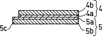
各负极6也同样,包含第1负极部分4及第2负极部分5。第1负极部分4包含带状的第1负极集电体4a及担载在其单面上的第1负极活性物质层4b。第2负极部分5包含带状的第2负极集电体5a及担载在其单面上的第2负极活性物质层5b。Similarly, each
在正极3中,第1正极部分1和第2正极部分2以使第1正极集电体1a的未担载有活性物质层的面与第2正极集电体2a的未担载有活性物质层的面重叠的方式层叠。在负极6中,第1负极部分4和第2负极部分5也以使第1负极集电体4a的未担载有活性物质层的面与第2负极集电体5a的未担载有活性物质层的面重叠的方式层叠。In the
隔膜7以Z字形折叠,构成具有交替地排列的第1电极收容部8及第2电极收容部10的层叠体。在图1中,层叠体具有4个第1电极(正极)收容部8和3个第2电极(负极)收容部10。此外,层叠体具有配有3个第1弯曲部11的第1端面及配有4个第2弯曲部9的第2端面。第1端面位于第2端面的相反侧。The
第1电极收容部8在第1端面侧具有开放部16,在第2端面侧具有第2弯曲部9。第2电极收容部10在第2端面侧具有开放部17,在第1端面侧具有第1弯曲部11。正极3被收容在第1电极收容部8内,负极6被收容在第2电极收容部10内。正极3的活性物质层和负极6的活性物质层经由隔膜7相对置。The first
另外,在图1中,第1电极收容部8及第2电极收容部10的断面为U字状。各电极收容部的断面不需要是严格地只由直线和曲线构成的形状,曲线部也可以是由直线构成的コ字状。或者,曲线线部也可以是由多条直线部构成的形状。此外,电极收容部的断面也可以是V字状。在实际的电池中,如果隔膜松弛,有时其断面成U字状。此外,如果对隔膜施加张力,有时其断面成V字状,或成コ字状。In addition, in FIG. 1, the cross section of the 1st
在本发明中,在第1电极及第2电极的至少一方中,2个电极部分的至少1个具有至少1个突部。图1表示在正极及负极的双方中,2个电极部分各自具有1个突部的情况。In the present invention, in at least one of the first electrode and the second electrode, at least one of the two electrode portions has at least one protrusion. FIG. 1 shows a case where two electrode portions each have one protrusion in both the positive electrode and the negative electrode.
正极3的2个电极部分分别具有向位于第1电极收容部8的第1端面上的开放部16侧突出的突部。负极6的2个电极部分分别具有向位于第2电极收容部10的第2端面上的开放部17侧突出的突部。这些突部由集电体和活性物质层构成。另外,在图1中,示出了设在第2正极部分2上的突部2c、及设置第1负极部分4上的突部4c。The two electrode portions of the
在设于正极上的突部突出的第1端面上,可形成第1端子(正极集电端子)12。在设于负极上的突部突出的第2端面上,可形成第2端子(负极集电端子)13。设在各正极上的突部连接在第1端子12上,设在各负极上的突部连接在第2端子13上。A first terminal (positive electrode current collector terminal) 12 can be formed on the first end surface protruding from the protruding portion provided on the positive electrode. A second terminal (negative electrode current collector terminal) 13 can be formed on the second end surface protruding from the protruding portion provided on the negative electrode. The protrusions provided on the positive electrodes are connected to the
如此,正极及负极通过分别具有突部,由此,特别是即使在集电体的厚度薄到0.1~5μm的情况下,也能通过活性物质层可靠地支撑集电体,同时集电体和端子的接触面积也增加。因此,能够可靠地进行集电体和端子的连接。此外,在本发明中,由于利用活性物质层支撑集电体,因此能够将集电体的厚度减薄到0.1~5μm。另外,如果集电体的厚度减薄到低于0.1μm,有时集电体的比电阻增大。In this way, the positive electrode and the negative electrode have protrusions respectively, thereby, even when the thickness of the current collector is as thin as 0.1 to 5 μm, the current collector can be reliably supported by the active material layer, and the current collector and the current collector can be reliably supported. The contact area of the terminal is also increased. Therefore, the connection between the current collector and the terminal can be reliably performed. Furthermore, in the present invention, since the current collector is supported by the active material layer, the thickness of the current collector can be reduced to 0.1 to 5 μm. In addition, when the thickness of the current collector is reduced to less than 0.1 μm, the specific resistance of the current collector may increase.
与隔膜的层叠体的厚度方向垂直的方向上的第1端子及第2端子的厚度分别优选为0.1mm~1mm。The thicknesses of the first terminal and the second terminal in a direction perpendicular to the thickness direction of the laminated body of the separator are preferably 0.1 mm to 1 mm.
另外,在第1端子12上连接有第1引线14,在第2端子13上连接有第2引线15。第1端子与所有的正极连接,第2端子与所有的负极连接。因此,即使在具有多个正极及负极的情况下,也能分别在第1端子及第2端子上连接引线端子。因此,不需要在全部电极上分别地连接引线端子。In addition, a
如图1所示,由于在第1端子12和第2电极6之间夹入隔膜7的第1弯曲部11,所以它们不会接触。由于在第2端子13和第1电极3之间夹入隔膜7的第2弯曲部9,所以它们不会接触。As shown in FIG. 1 , since the first
正极活性物质层含有正极活性物质。在是锂离子二次电池时,作为正极活性物质,例如,可采用含有锂的过渡金属氧化物。作为含有锂的过渡金属氧化物,例如,可列举出LixCoOz、LixNiOz、LixMnOz、LixCoyNi1-yOz、LixCofV1-fOz、LixNi1-yMyOz(M=Ti、V、Mn、Fe)、LixCoaNibMcOz(M=Ti、Mn、Al、Mg、Fe、Zr)、LixMn2O4、LixMn2 (1-y)M2yO4(M=Na、Mg、Sc、Y、Fe、Co、Ni、Ti、Zr、Cu、Zn、Al、Pb、Sb)等。其中,x值可根据电池的充放电,在0≤x≤1.2的范围内变化。此外,0≤y≤1、0.9≤f≤0.98、1.9≤z≤2.3、a+b+c=1、0≤a≤1、0≤b≤1、0≤c<1。这些金属氧化物可以单独使用,也可以组合两种以上使用。The positive electrode active material layer contains a positive electrode active material. In the case of a lithium ion secondary battery, for example, a transition metal oxide containing lithium can be used as the positive electrode active material. Examples of transition metal oxides containing lithium include Li x CoO z , Li x NiO z , Li x MnO z , Li x Co y Ni 1-y O z , Li x Co f V 1-f O z , Li x Ni 1-y M y O z (M = Ti, V, Mn, Fe), Li x Co a Ni b M c O z (M = Ti, Mn, Al, Mg, Fe, Zr), Li x Mn 2 O 4 , Li x Mn 2 (1-y) M 2y O 4 (M=Na, Mg, Sc, Y, Fe, Co, Ni, Ti, Zr, Cu, Zn, Al, Pb, Sb) wait. Wherein, the value of x can vary within the range of 0≤x≤1.2 according to the charging and discharging of the battery. In addition, 0≤y≤1, 0.9≤f≤0.98, 1.9≤z≤2.3, a+b+c=1, 0≤a≤1, 0≤b≤1, 0≤c<1. These metal oxides may be used alone or in combination of two or more.
另外,所用的正极活性物质可根据要制作的电池的种类适宜变更。In addition, the positive electrode active material used can be changed suitably according to the kind of battery to manufacture.
负极活性物质层含有负极活性物质。在是锂离子二次电池时,作为负极活性物质,例如,可采用锂、锂合金、金属间化合物、碳材料、硅(Si)、氧化硅(SiOx)、锡(Sn)、可嵌入及脱嵌锂离子的有机化合物或无机化合物、金属络合物以及有机高分子化合物。这些材料可以单独使用,也可以组合两种以上使用。The negative electrode active material layer contains a negative electrode active material. In the case of a lithium ion secondary battery, as the negative electrode active material, for example, lithium, lithium alloys, intermetallic compounds, carbon materials, silicon (Si), silicon oxide (SiO x ), tin (Sn), intercalated and Organic or inorganic compounds, metal complexes, and organic polymer compounds that deintercalate lithium ions. These materials may be used alone or in combination of two or more.
作为碳材料,可列举焦炭、热分解碳、天然石墨、人造石墨、中间相碳微球、石墨化中间相小球体、气相生长碳、玻璃状碳、碳纤维(聚丙烯腈系、沥青系、纤维系、气相生长系)、无规碳、有机化合物烧结体等。其中,尤其优选天然石墨或人造石墨。Examples of carbon materials include coke, pyrolytic carbon, natural graphite, artificial graphite, mesocarbon microspheres, graphitized mesophase spheres, vapor-grown carbon, glassy carbon, carbon fibers (polyacrylonitrile-based, pitch-based, fiber system, vapor phase growth system), random carbon, organic compound sintered body, etc. Among them, natural graphite or artificial graphite is particularly preferable.
在负极活性物质含有Si、SiOx及Sn中的至少一种时,负极活性物质层也可以是含有这些元素的沉积膜。When the negative electrode active material contains at least one of Si, SiO x and Sn, the negative electrode active material layer may be a deposited film containing these elements.
另外,负极活性物质的种类也可根据要制作的电池的种类适宜变更。In addition, the type of negative electrode active material can also be appropriately changed according to the type of battery to be produced.
正极活性物质层及负极活性物质层也可以根据需要含有导电材料及/或粘合剂。在是锂离子二次电池时,作为导电材料,例如,可采用乙炔黑等炭黑、及石墨。作为粘合剂,例如,可采用聚偏氟乙烯、聚四氟乙烯等氟树脂、丙烯系树脂、丁苯橡胶及乙烯丙烯三元共聚物。The positive electrode active material layer and the negative electrode active material layer may contain a conductive material and/or a binder as needed. In the case of a lithium ion secondary battery, carbon black such as acetylene black, and graphite can be used as the conductive material, for example. As the binder, for example, fluororesins such as polyvinylidene fluoride and polytetrafluoroethylene, acrylic resins, styrene-butadiene rubber, and ethylene-propylene terpolymers can be used.
导电材料及粘合剂的种类也可根据电池的种类适宜变更。The types of conductive material and binder can also be appropriately changed according to the type of battery.
作为正极集电体及负极集电体,可采用该领域公知的由金属材料构成的薄片或薄膜。在是锂离子二次电池时,作为构成正极集电体的材料可列举出铝。作为构成负极集电体的材料可列举出铜。As the positive electrode current collector and the negative electrode current collector, a sheet or film made of a metal material known in the art can be used. In the case of a lithium ion secondary battery, aluminum is used as a material constituting the positive electrode current collector. Examples of the material constituting the negative electrode current collector include copper.
作为构成第1端子即正极集电端子的材料,可采用该领域公知的材料。例如,作为正极集电端子,可采用金属铝薄膜、或由金属铝构成的多孔质膜。作为构成第2端子即负极集电端子的材料,可采用该领域公知的材料。例如,作为负极集电端子,可采用铜金属膜、或由铜构成的多孔质膜。另外,在第1电极是负极,第2电极是正极时,第1端子成为负极集电端子,第2端子成为正极集电端子。As the material constituting the first terminal, that is, the positive electrode collector terminal, materials known in the art can be used. For example, a metal aluminum thin film or a porous film made of metal aluminum can be used as the positive electrode current collector terminal. As a material constituting the second terminal, that is, the negative electrode collector terminal, materials known in the art can be used. For example, a copper metal film or a porous film made of copper can be used as the negative electrode current collector terminal. In addition, when the first electrode is a negative electrode and the second electrode is a positive electrode, the first terminal becomes a negative electrode collector terminal, and the second terminal becomes a positive electrode collector terminal.
第1端子及第2端子可通过真空蒸镀、溅射、喷镀等形成。此外,第1端子及第2端子也可以通过在各端面上涂布含有金属粒子的导电浆料,然后使其干燥来形成。The first terminal and the second terminal can be formed by vacuum evaporation, sputtering, spraying, or the like. In addition, the first terminal and the second terminal may be formed by applying a conductive paste containing metal particles on each end surface and drying it.
通过采用上述这样的第1端子及第2端子,能够可靠地进行这些端子和集电体的连接。By employing the first terminal and the second terminal as described above, the connection between these terminals and the current collector can be reliably performed.
关于隔膜,例如可采用由聚乙烯、聚丙烯等烯烃系聚合物、或玻璃纤维等构成的织布或无纺布。As the separator, for example, woven or nonwoven fabrics made of olefin-based polymers such as polyethylene and polypropylene, glass fibers, or the like can be used.
作为正极引线14和负极引线15,可采用该领域公知的材料。作为构成正极引线的材料,例如可采用金属铝。作为构成负极引线的材料,例如可采用金属镍。另外,在第1电极是负极,第2电极是正极时,第1引线为负极引线,第2引线为正极引线。As the
此外,第1引线及第2引线也可以分别埋入第1端子及第2端子。由此,能够更可靠地进行引线在端子上的连接。In addition, the first lead and the second lead may be embedded in the first terminal and the second terminal, respectively. Accordingly, it is possible to more reliably connect the lead wires to the terminals.
在图1中,在隔膜的层叠体的厚度方向的两端,配置有第1电极收容部8a及8b。被收容在第1电极收容部8a及8b内的正极优选分别由包含集电体和担载在其单面上的活性物质层的1个极板18及19构成。此时,收容在第1电极收容部8a及8b内的正极的活性物质层经由隔膜与邻接的收容在第2电极收容部内的负极的活性物质层相对置。In FIG. 1 , first
如图1所示,优选不用隔膜全部覆盖该集电体面,以使得收容在第1电极收容部8a及8b内的正极的正极集电体面的至少一部分向外部露出。由此,能可靠地从位于极板组的层叠方向的两端的极板进行集电。收容在第1电极收容部8a及8b内的电极可以具有突部,也可以不具有突部。另外,图1表示收容在第1电极收容部8a及8b内的电极不具有突部的电极群。As shown in FIG. 1 , it is preferable not to completely cover the current collector surface with a separator so that at least a part of the positive electrode current collector surface of the positive electrode accommodated in the first
接着,参照图2说明由2个第1电极夹着1个第2电极的极板组。在图2中,对于与图1相同的构成要素,附加相同的符号。Next, an electrode plate group in which one second electrode is sandwiched between two first electrodes will be described with reference to FIG. 2 . In FIG. 2 , the same reference numerals are attached to the same components as those in FIG. 1 .
图2所示的极板组具备2个第1电极21及22、1个第2电极23、以及带状的隔膜7。隔膜7以Z字形折叠,构成具有2个第1电极收容部26a及26b、和配置在它们之间的1个第2电极收容部27的层叠体。收容在第1电极收容部26a内的第1电极21由包含集电体21a和担载在其上的活性物质层21b的1块极板构成。同样,收容在第2电极收容部26b内的第1电极22由包含集电体22a和担载在其上的活性物质层22b的1块极板构成。即,在图2的极板组中,第1电极只具有1个电极部分。The electrode plate group shown in FIG. 2 includes two
第2电极23具有2个电极部分24及25。电极部分24包含集电体24a及担载在其单面上的活性物质层24b。电极部分25包含集电体25a及担载在其单面上的活性物质层25b。电极部分24和电极部分25以使集电体24a及集电体25a相互接触的方式配置。The
在图2的极板组中,第1电极21的活性物质层21b,经由隔膜7与第2电极23的活性物质层24b相对置,第1电极22的活性物质层22b,经由隔膜7与第2电极23的活性物质层25b相对置。2, the
第2电极的2个电极部分各自具有朝第2端面的开放部侧突出的突部。在图2中示出了第2电极23的电极部分24的突部24c。另外,在图2中,第1电极的电极部分没有突部。与第2电极同样,第1电极的电极部分也可以具有朝第1端面的开放部侧突出的突部。另外,设在各电极部分上的突部的个数可以是1个,也可以是2个以上。Each of the two electrode parts of the second electrode has a protrusion protruding toward the opening side of the second end face. In FIG. 2, the protrusion 24c of the
下面,参照附图分别说明正极3及负极6。在以下的附图中,对于与图1相同的构成要素,附加与图1相同的号码。Next, the
图3是正极3的俯视图,图4是正极3的仰视图。图5是按线A-A切断图3的正极时的纵剖视图。图6是按线B-B切断图3的正极时的纵剖视图。图7分别表示构成图3的正极的第1正极部分1及第2正极部分2。FIG. 3 is a plan view of the
如图3~图6所示,在正极中,第1正极部分1及第2正极部分2以使集电体1a的未担载有活性物质层的面与集电体2a的未担载有活性物质层的面接触的方式层叠。第1正极部分1具有突部1c,第2正极部分2具有突部2c。如图5所示,即使在以使集电体面彼此接触的方式层叠第1正极部分1和第2正极部分2的情况下,通过设置突部1c,能使第1正极部分1的正极集电体面露出。此外,如图6所示,通过设置突部2c,也能使第2正极部分2的正极集电体面露出。优选突部1c和突部2c不相互重叠。As shown in FIGS. 3 to 6 , in the positive electrode, the first
只要能可靠地进行突部和端子的连接,对突部的形状就不特别限定。例如,突部的形状也可以是如矩形、三角形或梯形。The shape of the protrusion is not particularly limited as long as the connection between the protrusion and the terminal can be reliably performed. For example, the shape of the protrusions may also be, for example, rectangular, triangular or trapezoidal.
与突部2c的宽度方向平行的边的长度Wt、与突部1c的宽度方向平行的边的长度Wu、和与正极的宽度方向平行的边的长度Ws之间的关系优选是Ws≥Wt+Wu,特别优选是Ws>Wt=Wu。由此,能够更可靠地连接各正极和第1端子。The relationship between the length Wt of the side parallel to the width direction of the
此外,突部1c中的集电体的露出面积Su和突部2c中的集电体的露出部St优选为同等面积。由此,能够通过第1正极部分和第2正极部分2使连接电阻相等。In addition, the exposed area Su of the current collector in the
突部的突出长度可以在0.5mm~1cm的范围。由此,能够充分得到本发明的效果。The protrusion length of the protrusion may be in the range of 0.5 mm to 1 cm. Thereby, the effect of this invention can fully be acquired.
下面,参照图8~图11说明负极6。Next, the
图8是负极6的俯视图,图9是负极6的仰视图。图10是按线C-C切断图8的负极时的纵剖视图,图11是按线D-D切断图8的负极时的纵剖视图。FIG. 8 is a top view of
如图8~图11所示,在负极6中,第1负极部分4及第2负极部分5以使集电体4a的未担载有活性物质层的面与集电体5a的未担载有活性物质层的面接触的方式层叠。第1负极部分4具有突部4c,第2电极部分5具有突部5c。如图10所示,即使在以使集电体面彼此接触的方式层叠第1负极部分4和第2负极部分5的情况下,通过设置突部4c,也能使第1负极部分4的负极集电体面露出。此外,如图11所示,通过设置突部5c,能使第2负极部分5的负极集电体面露出。与上述同样,优选突部4c和突部5c不相互重叠。As shown in FIGS. 8 to 11 , in the
与突部4c的宽度方向平行的边的长度Wy、与突部5c的宽度方向平行的边的长度Wx、和与负极的宽度方向平行的边的长度Wf之间的关系优选是Wf≥Wx+Wy,特别优选是Wf>Wx=Wy。优选,突部4c中的集电体的露出面积Sy和突部5c中的集电体的露出部Sx为同等面积。其理由与正极的情况相同。The relationship between the length Wy of the side parallel to the width direction of the
如图12及图13所示,2个电极部分各自也可以具有2个突部。As shown in FIGS. 12 and 13 , each of the two electrode portions may have two protrusions.
例如,在正极中,如图12所示,优选将设在第1正极部分1上的2个突部1c、和设在第2正极部分2上的2个突部2c交替地配置在正极的宽度方向。此外,优选各突部不相互重叠。For example, in the positive electrode, as shown in FIG. 12, it is preferable to alternately arrange the two
在负极中,如图13所示,优选将2个突部4c和2个突部5c交替地配置在负极的宽度方向。此外,优选各突部不重叠。In the negative electrode, as shown in FIG. 13 , it is preferable to arrange two
另外,在图12及图13中,在各电极部分设有2个突部,但设在各电极部分上的突部的个数也可以是3个以上。In addition, in FIGS. 12 and 13 , two protrusions are provided on each electrode portion, but the number of protrusions provided on each electrode portion may be three or more.
正极所含的2个电极部分,也可以通过以使集电体的未担载有活性物质层的面彼此接触的方式,将含有正极集电体和担载在其单面上的活性物质层的1块极板折弯来构成。或者,如图1所示,2个电极部分也可以通过以使集电体的未担载有活性物质层的面彼此接触的方式,将含有正极集电体和担载在其单面上的活性物质层的2块极板重叠来构成。The two electrode parts contained in the positive electrode may also contain the positive electrode current collector and the active material layer loaded on one side thereof by making the surfaces of the current collector not loaded with the active material layer contact each other. 1 plate is bent to form. Alternatively, as shown in FIG. 1 , the two electrode parts can also be composed of a positive electrode current collector and an active material layer loaded on one surface thereof in such a manner that the surfaces of the current collectors that are not loaded with the active material layer are in contact with each other. The two plates of the active material layer are formed by overlapping each other.
在通过折弯1块极板构成正极的情况下,突部可分别设在与该极板的折弯轴平行的2个边上。此时,这些突部在折弯极板时以不相互重叠的方式配置。设在各边上的突部的个数可以是1个,也可以是2个以上。When the positive electrode is formed by bending one electrode plate, the protrusions may be respectively provided on two sides parallel to the bending axis of the electrode plate. At this time, these protrusions are arranged so as not to overlap each other when the electrode plate is bent. The number of protrusions provided on each side may be one or two or more.
或者,也可以只在正极的1个电极部分上,在极板的整个宽度方向设置突部。图14表示正极只具有突部2c,突部2c设置在极板的整个宽度方向时的情况。Alternatively, only one electrode portion of the positive electrode may be provided with protrusions over the entire width direction of the electrode plate. FIG. 14 shows a case where the positive electrode has only the protruding
在由1块极板构成正极的情况下,图14的正极可通过在折弯1块极板时,将与极板的折弯轴平行的2个边的位置在极板的长度方向上错开来制作。In the case where the positive electrode is constituted by one pole plate, the positive pole in Fig. 14 can be staggered in the length direction of the pole plate by shifting the positions of the two sides parallel to the bending axis of the pole plate when bending one pole plate to make.
在正极由2块极板构成的情况下,可在这些极板的相同的端部上设置突部,同时使这些突部不相互重叠。In the case where the positive electrode is composed of two plates, protrusions may be provided on the same ends of these plates without overlapping the protrusions.
另外,这些构成在负极中也同样。In addition, these configurations are also the same in the negative electrode.
在锂离子二次电池中,如果正极的尺寸大于负极的尺寸,则在充放电时有时在负极侧产生锂的枝状物。因此,优选正极的尺寸小于负极。即,与图4所示的正极的长度方向平行的边和突部的长度的合计Ls优选短于与图9所示的负极的长度方向平行的边的长度Lf(除去突部的长度)。此外,与正极的宽度方向平行的边的长度Ws优选短于与负极的宽度方向平行的边的长度Wf。In a lithium ion secondary battery, if the size of the positive electrode is larger than that of the negative electrode, lithium dendrites may be generated on the negative electrode side during charge and discharge. Therefore, it is preferable that the positive electrode is smaller in size than the negative electrode. That is, the sum Ls of the lengths of the side parallel to the longitudinal direction of the positive electrode shown in FIG. 4 and the length of the protrusion is preferably shorter than the length Lf of the side parallel to the longitudinal direction of the negative electrode shown in FIG. 9 (excluding the length of the protrusion). In addition, the length Ws of the side parallel to the width direction of the positive electrode is preferably shorter than the length Wf of the side parallel to the width direction of the negative electrode.
在正极及负极中,可根据电池的容量设计而适宜变更担载在集电体上的活性物质层的厚度。例如,活性物质层的厚度可设定在1μm~150μm。In the positive electrode and the negative electrode, the thickness of the active material layer supported on the current collector can be appropriately changed according to the capacity design of the battery. For example, the thickness of the active material layer can be set at 1 μm to 150 μm.
接着,示出图1所示的极板组的一例制作方法。Next, an example of a manufacturing method of the electrode plate group shown in FIG. 1 will be described.
首先,参照图15说明正极及负极的一例制作方法。First, an example of a method for producing a positive electrode and a negative electrode will be described with reference to FIG. 15 .
(A)正极的制作(A) Fabrication of the positive electrode
准备图15(a)所示的规定尺寸的附有脱模剂(剥离剂)32的树脂薄片31。作为脱模剂,最好采用黑色素系且不含Si的。因为如果含有Si,有时难以从树脂薄片上剥离金属膜。A
接着,在树脂薄片31的脱模剂32上,覆盖具有规定形状的、规定尺寸的开口部的掩模。使规定的金属沉积在从树脂薄片31的开口部露出的部分上,形成由金属薄膜构成的正极集电体33(图15(b))。此时,金属的沉积可采用蒸镀法等进行。Next, a mask having openings of a predetermined shape and a predetermined size is covered on the
接着,在正极集电体33的整面上涂敷正极合剂浆料,并使其干燥。然后,压延干燥后的涂膜,在集电体上形成正极活性物质层34(图15(c))。涂膜的压延,例如可采用辊进行。另外,通过压延干燥后的涂膜,可提高活性物质层的密度。Next, the positive electrode mixture slurry is applied to the entire surface of the positive electrode
正极合剂浆料可通过将正极活性物质、导电材料、粘合剂等按规定的比例与分散剂混合来调制。The positive electrode mixture slurry can be prepared by mixing a positive electrode active material, a conductive material, a binder, and the like with a dispersant in a prescribed ratio.
在要制作的电池是锂离子二次电池时,能够采用上述这样的正极活性物质、导电材料及粘合剂。此外,分散剂可根据所用的活性物质、导电材料、粘合剂的种类而适宜选择。When the battery to be manufactured is a lithium ion secondary battery, the above-mentioned positive electrode active material, conductive material, and binder can be used. In addition, the dispersant can be appropriately selected according to the type of active material, conductive material, and binder to be used.
正极合剂浆料的在集电体上的涂敷方法,不特别限定,可采用在该领域公知的方法。例如,可采用丝网印刷及布图涂敷。The method of coating the positive electrode mixture slurry on the current collector is not particularly limited, and a method known in the art can be used. For example, screen printing and pattern coating can be used.
接着,将得到的层叠薄片切断成规定的尺寸及形状,得到极板前体。此时,在极板前体上设有至少1个突部。Next, the obtained laminated sheet is cut into a predetermined size and shape to obtain an electrode plate precursor. At this time, at least one protrusion is provided on the electrode plate precursor.
接着,从集电体33剥离具备脱模剂32的树脂薄片31(图15(d))。由此,可得到含有正极集电体和担载在其上的正极活性物质层的、形成有突部的极板。但在图15中未示出突部。Next, the
如此制作2块极板,以使集电体面彼此接触的方式层叠这两块极板,由此可得到正极。此时,以突部位于正极的相同端部的方式层叠2块极板。In this way, two electrode plates are produced, and the two electrode plates are laminated so that the surfaces of the current collectors are in contact with each other, whereby a positive electrode can be obtained. At this time, two electrode plates were stacked so that the protrusions were located at the same end of the positive electrode.
或者,制作在两端分别具备至少1个突部的1块极板,通过以使集电体彼此重叠的方式折弯该极板,也能得到正极。此时,突部仅设置在极板的一个端部。Alternatively, a positive electrode can also be obtained by manufacturing one electrode plate having at least one protrusion at both ends, and bending the electrode plate so that current collectors overlap each other. At this time, the protrusion is provided only at one end of the pole plate.
(B)负极的制作(B) Preparation of negative electrode
基本上能与正极相同地制作负极。Basically, the negative electrode can be produced in the same manner as the positive electrode.
准备规定尺寸的附有脱模的树脂薄片。在树脂薄片的脱模剂上,覆盖具有规定形状、规定尺寸的开口部的掩模。使规定的金属沉积在从树脂薄片的开口部露出的部分上,形成负极集电体。Prepare a resin sheet with a mold release of the specified size. A mask having openings of a predetermined shape and a predetermined size is covered on the release agent of the resin sheet. A predetermined metal is deposited on the portion exposed from the opening of the resin sheet to form a negative electrode current collector.
接着,在负极集电体的整面上涂敷负极合剂浆料,并使其干燥。然后,压延干燥后的涂膜,在集电体上形成负极活性物质层。Next, the negative electrode mixture slurry was applied on the entire surface of the negative electrode current collector, and dried. Then, the dried coating film was rolled to form a negative electrode active material layer on the current collector.
负极合剂浆料可通过将负极活性物质、导电材料、根据需要的粘合剂等按规定的比例与分散剂混合来调制。The negative electrode mixture slurry can be prepared by mixing a negative electrode active material, a conductive material, and if necessary, a binder, etc., with a dispersant in a predetermined ratio.
在要制作的电池是锂离子二次电池时,能够采用上述这样的负极活性物质、导电材料及粘合剂。此外,分散剂可根据所用的活性物质、导电材料、粘合剂的种类而适宜选择。When the battery to be manufactured is a lithium ion secondary battery, the above-mentioned negative electrode active material, conductive material, and binder can be used. In addition, the dispersant can be appropriately selected according to the type of active material, conductive material, and binder to be used.
在负极活性物质含有Si、SiOx及Sn中的至少一种时,负极活性物质层也可以是含有该至少一种元素的沉积膜。该沉积膜例如可采用溅射法及蒸镀法制作。When the negative electrode active material contains at least one of Si, SiOx and Sn, the negative electrode active material layer may also be a deposited film containing the at least one element. The deposited film can be produced by, for example, sputtering and vapor deposition.
接着,将得到的层叠薄片切断成规定的尺寸及形状,得到极板前体。此时,在极板前体上设有至少1个突部。Next, the obtained laminated sheet is cut into a predetermined size and shape to obtain an electrode plate precursor. At this time, at least one protrusion is provided on the electrode plate precursor.
接着,从集电体上剥离具备脱模剂的树脂薄片。由此,可得到含有负极集电体和担载在其上的负极活性物质层的、形成有突部的极板。Next, the resin sheet provided with the release agent was peeled off from the current collector. As a result, an electrode plate on which protrusions are formed, including a negative electrode current collector and a negative electrode active material layer supported thereon, can be obtained.
与正极的情况同样地,通过以使集电体面彼此接触的方式层叠2块极板,可得到负极。或者,制作在两端分别具备至少1个突部的1块极板,通过以使集电体彼此重叠的方式折弯该极板,也能得到负极。As in the case of the positive electrode, the negative electrode can be obtained by stacking two electrode plates so that the current collector surfaces are in contact with each other. Alternatively, a negative electrode can also be obtained by manufacturing one electrode plate having at least one protrusion at both ends, and bending the electrode plate so that current collectors overlap each other.
另外,采用以往一般所用的由金属箔构成的集电体,也能制作正极及负极。In addition, a positive electrode and a negative electrode can also be produced by using a conventional current collector made of metal foil.
(C)极板组的组装(C) Assembly of plate group
通过将1块带状的隔膜进行Z字形折叠,得到第1电极收容部和第2电极收容部交替排列的层叠体。得到的层叠体具有4个第1电极收容部和3个第2电极收容部。A laminated body in which the first electrode housing portions and the second electrode housing portions are alternately arranged was obtained by zigzag-folding one strip-shaped separator. The obtained laminated body had four 1st electrode accommodating parts and 3 2nd electrode accommodating parts.
如图16~图18所示,或图19~图21所示,将得到的正极及负极配置在第1电极收容部和第2电极收容部中。此时,经由隔膜使正极的正极活性物质层和负极的负极活性物质层相对置。As shown in FIGS. 16 to 18 , or as shown in FIGS. 19 to 21 , the obtained positive electrode and negative electrode are arranged in the first electrode accommodating portion and the second electrode accommodating portion. At this time, the positive electrode active material layer of the positive electrode and the negative electrode active material layer of the negative electrode are opposed to each other through the separator.
在图16~图18和图19~图21中,在正极3中,设在第1正极部分上的突部1c和设在第2正极部分上的突部2c的位置相互相反。In FIGS. 16 to 18 and FIGS. 19 to 21 , in the
图16是经由隔膜层叠1个正极和1个负极时的俯视图。图17是图16的线E-E处的纵剖视图,图18是图16的线F-F处的纵剖视图。Fig. 16 is a plan view when one positive electrode and one negative electrode are laminated via a separator. 17 is a longitudinal sectional view taken along line E-E of FIG. 16 , and FIG. 18 is a longitudinal sectional view taken along line F-F of FIG. 16 .
图19是经由隔膜层叠1个负极和突部位置与图16的正极不同的1个正极时的俯视图。图20表示图19的线G-G处的纵剖视图,图21表示图19的线H-H处的纵剖视图。FIG. 19 is a plan view of a case where one negative electrode and one positive electrode having a protrusion position different from that of the positive electrode of FIG. 16 are stacked via a separator. FIG. 20 shows a longitudinal sectional view taken along line G-G in FIG. 19 , and FIG. 21 shows a longitudinal sectional view taken along line H-H in FIG. 19 .
另外,在图16及图19中未示出隔膜。In addition, the diaphragm is not shown in FIGS. 16 and 19 .
通过按如上所述,经由隔膜交替地层叠4个正极3和3个负极6,可得到图22所示的结构物。By alternately laminating four
在隔膜的层叠体的厚度方向的两端的第1电极收容部内,分别配置包含正极集电体和担载在其单面上的正极活性物质层的1块极板。配置在两端的电极收容部内的正极的活性物质层,分别经由隔膜与邻接的收容在第2电极收容部内的负极的活性物质层相对置。One electrode plate including a positive electrode current collector and a positive electrode active material layer carried on one surface thereof is placed in the first electrode housing portions at both ends of the separator laminate in the thickness direction. The active material layers of the positive electrodes arranged in the electrode housing portions at both ends face the active material layers of the adjacent negative electrodes housed in the second electrode housing portions via the separators.
接着,通过在正极及负极的层叠方向上冲压得到的结构物整体,可得到由多个正极、负极及隔膜构成的集合体。另外,该冲压可根据需要实施。Next, by punching the entire structure obtained in the stacking direction of the positive electrode and the negative electrode, an assembly composed of a plurality of positive electrodes, negative electrodes, and separators can be obtained. In addition, this punching can be performed as needed.
正极和负极的位置也可以调换。在此种情况下,在上述集合体的层叠方向的两端的收容部,分别配置由1个负极部分构成的负极。The positions of the positive and negative poles can also be reversed. In this case, negative electrodes consisting of one negative electrode part are arranged in the housing portions at both ends of the assembly in the stacking direction.
接着,如图23所示,在正极3的突部露出的区域(第1端面)上,形成第1端子(正极集电端子)12,并联连接各正极。第1端子12例如可通过向第1端面喷涂熔化状态或半熔化状态的规定的金属来制作。Next, as shown in FIG. 23 , a first terminal (positive electrode collector terminal) 12 is formed on the region (first end surface) where the protrusion of the
同样,在负极6的突部露出的第2端面上,形成第2端子(负极集电端子)13,并联连接各负极。第2端子13例如可通过向第2端面以熔化状态或半熔化状态喷涂例如与构成第1端子的金属不同的金属来制作。Similarly, a second terminal (negative electrode collector terminal) 13 is formed on the second end surface where the protruding portion of the
熔化状态或半熔化状态的金属的喷涂,例如可通过采用压缩空气,使熔化状态或半熔化状态的金属从喷嘴喷出来进行。The spraying of molten or semi-molten metal can be performed, for example, by spraying the molten or semi-molten metal from a nozzle using compressed air.
接着,通过在第1端子12上安装正极引线14,在第2端子13上安装负极引线15,可构成图1所示的电极群。Next, by attaching the
另外,极板组的没有第1端子及第2端子的其它区域,可以维持原状,也可以用绝缘材料覆盖。In addition, other regions of the electrode plate group without the first terminal and the second terminal may be kept as they are, or may be covered with an insulating material.
正极引线14可通过向第1端子12喷镀金属铝等来设置。此外,也可以在第1端子上焊接由金属铝等构成的金属引线,将其作为正极引线。同样,负极引线15也可通过向第2端子13喷镀金属镍等来设置。或者,也可以在第2端子上焊接由金属镍等构成的金属引线,将其作为负极引线。The
也可以将正极引线14及负极引线15分别埋入第1端子12及第2端子13内。例如,正极引线的埋入,例如可通过在形成第1端子后,将正极引线配置在第1端子上,从其上方再次喷镀构成第1端子的金属来进行。负极引线的埋入也相同。The
图1所示的极板组通常与电解液一同收容在规定的电池壳内,然后密封该电池壳的开口部,做成电池。The electrode plate group shown in FIG. 1 is usually housed in a predetermined battery case together with an electrolyte, and the opening of the battery case is sealed to form a battery.
对电池壳的形状、材质等不特别限定。例如,作为电池壳,可采用以规定形状加工不锈钢板、铝板等而成的壳体、由两面具有树脂覆膜的铝箔(层压铝薄板)构成的壳体、树脂壳体等。The shape, material, etc. of the battery case are not particularly limited. For example, as the battery case, a case formed by processing a stainless steel plate or an aluminum plate into a predetermined shape, a case made of aluminum foil (laminated aluminum sheet) with a resin coating on both sides, a resin case, etc. can be used.
所使用的电解液的种类可根据电池的种类而适宜变更。例如,锂离子二次电池中所用的电解液,由非水溶液和溶解于非水溶液中的锂盐构成。在此种情况下,溶解于电解液中的锂盐的浓度优选设定为0.5~1.5mol/L。The type of electrolytic solution used can be appropriately changed according to the type of battery. For example, an electrolytic solution used in a lithium ion secondary battery consists of a non-aqueous solution and a lithium salt dissolved in the non-aqueous solution. In this case, the concentration of the lithium salt dissolved in the electrolytic solution is preferably set to 0.5 to 1.5 mol/L.
作为非水溶剂,例如,可采用碳酸亚乙酯、碳酸亚丙酯、碳酸亚丁酯、碳酸亚乙烯酯等环状碳酸酯,碳酸二甲酯、碳酸二乙酯、碳酸甲乙酯、碳酸乙丙酯、碳酸甲丙酯、碳酸甲基异丙基酯、碳酸二丙酯等非环状碳酸酯,甲酸甲酯、乙酸甲酯、丙酸甲酯、丙酸乙酯等脂肪族羧酸酯、γ—丁内酯、γ—戊内酯等γ—内酯,1,2—二甲氧基乙烷、1,2—二乙氧基乙烷、乙氧基甲氧基乙烷等非环状醚,四氢呋喃、2—甲基—四氢呋喃等环状醚,二甲亚砜、1,3—二氧杂环戊烷、磷酸三甲酯、磷酸三乙酯、磷酸三辛酯等烷基磷酸酯,及它们的氟化物。这些非水溶剂,可以单独使用,也可以组合两种以上使用。其中,优选为含有环状碳酸酯和非环状碳酸酯的混合物,以及含有环状碳酸酯、非环状碳酸酯和脂肪族羧酸酯的混合物等。As the non-aqueous solvent, for example, cyclic carbonates such as ethylene carbonate, propylene carbonate, butylene carbonate, vinylene carbonate, dimethyl carbonate, diethyl carbonate, ethyl methyl carbonate, ethylene carbonate, etc. Propyl, methyl propyl carbonate, methyl isopropyl carbonate, dipropyl carbonate and other acyclic carbonates, methyl formate, methyl acetate, methyl propionate, ethyl propionate and other aliphatic carboxylates , γ-butyrolactone, γ-valerolactone and other γ-lactones, 1,2-dimethoxyethane, 1,2-diethoxyethane, ethoxymethoxyethane and other non- Cyclic ethers, tetrahydrofuran, 2-methyl-tetrahydrofuran and other cyclic ethers, dimethyl sulfoxide, 1,3-dioxolane, trimethyl phosphate, triethyl phosphate, trioctyl phosphate and other alkyl groups Phosphates, and their fluorides. These nonaqueous solvents may be used alone or in combination of two or more. Among them, a mixture containing a cyclic carbonate and an acyclic carbonate, a mixture containing a cyclic carbonate, an acyclic carbonate, and an aliphatic carboxylate, and the like are preferable.
关于锂盐,例如,可采用LiPF6、LiBF4、LiClO4、LiAlCl4、LiSbF6、LiSCN、LiCl、LiCF3SO3、LiCF3CO2、LiAsF6、LiN(CF3SO2)2、Li2B10Cl10、LiN(C2F5SO2)2、LiPF3(CF3)3及LiPF3(C2F5)3。这些材料,可以单独使用,也可以组合两种以上使用。锂盐优选至少含有LiPF6。As for the lithium salt, for example, LiPF 6 , LiBF 4 , LiClO 4 , LiAlCl 4 , LiSbF 6 , LiSCN, LiCl, LiCF 3 SO 3 , LiCF 3 CO 2 , LiAsF 6 , LiN(CF 3 SO 2 ) 2 , Li 2 B 10 Cl 10 , LiN(C 2 F 5 SO 2 ) 2 , LiPF 3 (CF 3 ) 3 and LiPF 3 (C 2 F 5 ) 3 . These materials may be used alone or in combination of two or more. The lithium salt preferably contains at least LiPF 6 .
采用以上说明的制造方法,例如,只要是在长为10~300mm、宽为10~300mm、厚为0.1~5mm的范围内,就能高效率地制造任意尺寸的极板组。According to the manufacturing method described above, for example, as long as the length is 10 to 300 mm, the width is 10 to 300 mm, and the thickness is 0.1 to 5 mm, an electrode plate group of any size can be efficiently manufactured.
实施例1Example 1
以下,基于实施例来说明本发明。在本实施例中,制作了锂离子二次电池。在制作的电池中,以第1电极作为正极,以第2电极作为负极。另外,以下的实施例并不限定本发明。Hereinafter, the present invention will be described based on examples. In this example, a lithium ion secondary battery was produced. In the produced battery, the first electrode was used as the positive electrode, and the second electrode was used as the negative electrode. In addition, the following Examples do not limit this invention.
(电池A)(Battery A)
(A)正极的制作(A) Fabrication of the positive electrode
准备规定长度的附有脱模剂的聚对苯二甲酸乙二酯(PET)薄膜。该PET薄膜的宽度为100mm,厚度为7μm。Prepare a predetermined length of polyethylene terephthalate (PET) film with a release agent. The PET film had a width of 100 mm and a thickness of 7 μm.
采用规定的蒸镀装置及开口部尺寸为80mm×50mm的掩模,在PET薄膜的具备脱模剂的面上形成正极集电体即Al蒸镀膜。形成的Al蒸镀膜的宽度为80mm,长度为1m,厚度为1μm。Using a predetermined vapor deposition device and a mask with an opening size of 80 mm×50 mm, an Al vapor-deposited film, which is a positive electrode current collector, was formed on the surface of the PET film provided with a release agent. The formed Al vapor-deposited film had a width of 80 mm, a length of 1 m, and a thickness of 1 μm.
通过混合正极活性物质即钴酸锂(LiCoO2)100重量份、导电材料即乙炔炭黑3重量份、粘合剂即聚偏氟乙烯7重量份和分散剂即适量的羧甲基纤维素水溶液,调制了正极合剂浆料。将该浆料涂敷在Al蒸镀膜的整面上,形成宽80mm、长1m的涂膜层。然后,干燥该涂膜层,用辊压延到厚70μm,得到正极活性物质层。By mixing 100 parts by weight of lithium cobaltate (LiCoO 2 ) as the positive electrode active material, 3 parts by weight of acetylene carbon black as the conductive material, 7 parts by weight of polyvinylidene fluoride as the binder, and an appropriate amount of carboxymethyl cellulose aqueous solution as the dispersant , prepared the positive electrode mixture slurry. This slurry was coated on the entire surface of the Al vapor-deposited film to form a coating film layer with a width of 80 mm and a length of 1 m. Then, the coating film layer was dried and rolled to a thickness of 70 μm with a roll to obtain a positive electrode active material layer.
接着,冲裁由附有脱模剂的PET薄膜、正极集电体及正极活性物质层构成的层叠体,得到极板前体。极板前体具有在长150mm×宽45mm的长方形中设有2个突部的形状。突部的形状为矩形。此处,第1突部设在与该长方形的宽度方向平行的边的一方上,第2突部设在另一方的边上。突部的突出长度为3mm,突部的宽度为10mm。另外,与突部的突出方向平行的边,与上述长方形的长度方向平行。与突部的宽度方向平行的边,与上述长方形的宽度方向平行。Next, a laminate composed of the PET film with a release agent, the positive electrode current collector, and the positive electrode active material layer was punched out to obtain an electrode plate precursor. The electrode plate precursor had a shape in which two protrusions were provided in a rectangle with a length of 150 mm x a width of 45 mm. The shape of the protrusion is rectangular. Here, the first protrusion is provided on one side parallel to the width direction of the rectangle, and the second protrusion is provided on the other side. The protrusion length of the protrusion was 3 mm, and the width of the protrusion was 10 mm. In addition, the side parallel to the protruding direction of the protrusion is parallel to the longitudinal direction of the above-mentioned rectangle. The side parallel to the width direction of the protrusion is parallel to the width direction of the above-mentioned rectangle.
第1突部的与宽度方向平行的边的中心位置、和第2突部的与宽度方向平行的边的中心位置,从与上述长方形的宽度方向平行的边的中心位置,相互向相反方向错开5mm。The center position of the side parallel to the width direction of the first protrusion and the center position of the side parallel to the width direction of the second protrusion are shifted in opposite directions from the center position of the side parallel to the width direction of the above-mentioned rectangle. 5mm.
从极板前体揭下附有脱模剂的PET薄膜,得到由具备2个突部的正极集电体和担载在其上的正极活性物质层构成的正极板。The PET film with the release agent was removed from the electrode plate precursor to obtain a positive electrode plate composed of a positive electrode current collector having two protrusions and a positive electrode active material layer supported thereon.
通过与极板的长度方向平行的边的中心,在和与宽度方向平行的边平行的折弯轴处,朝集电体面相互接触的方向折弯得到的极板,得到尺寸为(75mm+突部3mm)×45mm的正极。此时,第1及第2突部,由于其位置向相反方向错开,所以不会相互重叠。Through the center of the side parallel to the length direction of the pole plate, at the bending axis parallel to the side parallel to the width direction, the pole plate obtained by bending toward the direction in which the surfaces of the current collectors are in contact with each other has a size of (75 mm+protrusions) 3mm) × 45mm positive electrode. At this time, since the positions of the first and second protrusions are shifted in opposite directions, they do not overlap each other.
如此,准备4个正极。In this way, four positive electrodes were prepared.
另外,准备好2个包含正极集电体和担载在其单面上的正极活性物质层的极板。这些极板可通过切断按上述得到的正极板而得到。In addition, two electrode plates including a positive electrode current collector and a positive electrode active material layer carried on one surface thereof were prepared. These plates can be obtained by cutting the positive plate obtained above.
(B)负极的制作(B) Preparation of negative electrode
准备规定长度的附有脱模剂的PET薄膜。PET薄膜的宽度为100mm,厚度为7μm。Prepare a PET film with a release agent of a specified length. The PET film has a width of 100 mm and a thickness of 7 μm.
接着,采用规定的蒸镀装置及开口部尺寸为80mm×50mm的掩模,在PET薄膜的具备脱模剂的面上,形成负极集电体即Cu蒸镀膜。形成的Cu蒸镀膜的宽度为80mm,长度为1m,厚度为1μm。Next, using a predetermined vapor deposition device and a mask with an opening size of 80 mm×50 mm, a Cu vapor-deposited film that is a negative electrode current collector was formed on the surface of the PET film provided with a release agent. The formed Cu vapor-deposited film had a width of 80 mm, a length of 1 m, and a thickness of 1 μm.
通过混合负极活性物质即球状石墨(石墨化中间相小球体)100重量份、粘合剂即丁苯橡胶10重量份和分散剂即适量的羧甲基纤维素水溶液,调制了负极合剂浆料。Negative electrode mixture slurry was prepared by mixing 100 parts by weight of spherical graphite (graphitized mesophase small spheres) as the negative electrode active material, 10 parts by weight of styrene-butadiene rubber as the binder, and an appropriate amount of carboxymethyl cellulose aqueous solution as the dispersant.
将该浆料涂敷在Cu蒸镀膜的整面上,形成宽80mm、长1m的涂膜层。然后,干燥该涂膜层,用辊压延到厚73μm,得到负极活性物质层。This slurry was applied on the entire surface of the Cu vapor-deposited film to form a coating film layer with a width of 80 mm and a length of 1 m. Then, the coating film layer was dried and rolled to a thickness of 73 μm with a roll to obtain a negative electrode active material layer.
接着,冲裁由附有脱模剂的PET薄膜、负极集电体及负极活性物质层构成的层叠片,得到极板前体。极板前体具有在长160mm×宽47mm的长方形中设有2个突部的形状。与正极的情况同样,突部的形状为矩形。第1突部设在与该长方形的宽度方向平行的边的一方上,第2突部设在与长方形的宽度方向平行的另一方的边上。突部的突出长度为3mm,突部的宽度为10mm。另外,与突部的突出方向平行的边,与上述长方形的长度方向平行。与突部的宽度方向平行的边,与上述长方形的宽度方向平行。Next, a laminate sheet composed of a PET film with a release agent, a negative electrode current collector, and a negative electrode active material layer was punched out to obtain an electrode plate precursor. The electrode plate precursor had a shape in which two protrusions were provided in a rectangle with a length of 160 mm x a width of 47 mm. As in the case of the positive electrode, the protrusion has a rectangular shape. The first protrusion is provided on one side parallel to the width direction of the rectangle, and the second protrusion is provided on the other side parallel to the width direction of the rectangle. The protrusion length of the protrusion was 3 mm, and the width of the protrusion was 10 mm. In addition, the side parallel to the protruding direction of the protrusion is parallel to the longitudinal direction of the above-mentioned rectangle. The side parallel to the width direction of the protrusion is parallel to the width direction of the above-mentioned rectangle.
第1突部的与宽度方向平行的边的中心位置、和第2突部的与宽度方向平行的边的中心位置,从与上述长方形的宽度方向平行的边的中心位置,相互向相反方向错开5mm。The center position of the side parallel to the width direction of the first protrusion and the center position of the side parallel to the width direction of the second protrusion are shifted in opposite directions from the center position of the side parallel to the width direction of the above-mentioned rectangle. 5mm.
从极板前体上揭下附有脱模剂的PET薄膜,得到由具备2个突部的负极集电体和担载在其上的负极活性物质层构成的负极板。The PET film with the release agent was removed from the electrode plate precursor to obtain a negative electrode plate composed of a negative electrode current collector having two protrusions and a negative electrode active material layer carried thereon.
通过与极板的长度方向平行的边(160mm的边)的中心,在和与宽度方向平行的边(47mm的边)平行的折弯轴处,以使集电体面相互接触的方式折弯得到的极板,得到尺寸为(80mm+突部3mm)×47mm的负极。此时,如上所述,各突部由于其位置向相反方向错开,所以不会相互重叠。Through the center of the side parallel to the longitudinal direction of the electrode plate (160 mm side), it is bent at the bending axis parallel to the side parallel to the width direction (47 mm side) so that the current collector surfaces are in contact with each other. A negative electrode with a size of (80mm+protrusion 3mm)×47mm was obtained. At this time, as described above, since the positions of the protrusions are shifted in opposite directions, they do not overlap each other.
如此地准备4个负极。Four negative electrodes are thus prepared.
(C)极板组的制作(C) Production of plate group
准备宽50mm、长814mm、厚0.016mm的隔膜。作为隔膜,采用由聚丙烯层、聚乙烯层及聚丙烯层这3层结构构成的隔膜。A separator having a width of 50 mm, a length of 814 mm, and a thickness of 0.016 mm was prepared. As the separator, a separator having a three-layer structure of a polypropylene layer, a polyethylene layer, and a polypropylene layer was used.
将该隔膜从一方的端部在长为75mm的位置处折弯。接着,在前进83mm的位置处向相反方向折弯,接着,在前进83mm的位置处再向与前次折弯的方向相反方向折弯。如此将隔膜折弯9次,得到层叠体。在从折叠的方向看该层叠体时,其尺寸为宽50mm×长83mm。此处,位于最上部及最下部的外侧的隔膜,为了使电极的突部的集电体面露出,将其长度缩短到75mm。This separator was bent at a position of 75 mm in length from one end. Next, bend in the opposite direction at the position advanced by 83 mm, and then bend in the opposite direction to the previous bending direction at the position advanced by 83 mm. In this way, the separator was bent 9 times to obtain a laminated body. When this laminated body is seen from the folding direction, the size is 50 mm in width x 83 mm in length. Here, the length of the separator located outside the uppermost and lowermost parts was shortened to 75 mm in order to expose the current collector surface of the protruding part of the electrode.
通过折叠隔膜得到的层叠体,具有配置了4个第1弯曲部的第1端面、和配置了5个第2弯曲部的第2端面。另外,在层叠体中,第1侧面位于第2端面的相反侧。The laminate obtained by folding the separator has a first end surface on which four first bent portions are arranged, and a second end surface on which five second bent portions are arranged. In addition, in the laminated body, the first side surface is located on the opposite side to the second end surface.
在5个第1电池收容部中,位于最上部的收容部和位于最下部的收容部以外的收容部中,分别以突部向第1端面的开放部侧突出的方式,配置了由2个电极部分构成的正极。在处于最上部及最下部的收容部中,配置了由正极集电体和担载在其单面上的正极活性物质层构成的1块极板。此时,正极活性物质层经由隔膜与负极活性物质层相对置。Among the five first battery housing parts, in the housing part located at the uppermost part and the housing parts other than the housing part located at the lowermost part, two batteries are arranged in such a manner that the protruding parts protrude toward the opening part side of the first end face. The electrode part constitutes the positive electrode. One electrode plate composed of a positive electrode current collector and a positive electrode active material layer carried on one surface thereof is placed in the uppermost and lowermost housing portions. At this time, the positive electrode active material layer faces the negative electrode active material layer via the separator.
在4个第2电极收容部的各自中,以突部向第2端面侧突出的方式配置了负极。In each of the four second electrode accommodating portions, a negative electrode is arranged such that the protruding portion protrudes toward the second end face side.
接着,通过冲压得到的结构物整体,得到集合体。Next, the entire obtained structure is punched to obtain an aggregate.
在得到的集合体的纵断面上,从上方依次配置有隔膜、正极集电体、正极活性物质层、隔膜、负极活性物质层、负极集电体、负极活性物质层、隔膜、正极活性物质层、正极集电体、正极活性物质层、隔膜、负极活性物质层、负极集电体、负极活性物质层、隔膜、正极活性物质层、正极集电体、正极活性物质层、隔膜、负极活性物质层、负极集电体、负极活性物质层、隔膜、正极活性物质层、正极集电体、正极活性物质层、隔膜、负极活性物质层、负极集电体、负极活性物质层、隔膜、正极活性物质层、正极集电体、及隔膜。On the longitudinal section of the obtained assembly, a separator, a positive electrode current collector, a positive electrode active material layer, a separator, a negative electrode active material layer, a negative electrode current collector, a negative electrode active material layer, a separator, and a positive electrode active material layer are sequentially arranged from above. , positive electrode current collector, positive electrode active material layer, separator, negative electrode active material layer, negative electrode current collector, negative electrode active material layer, separator, positive electrode active material layer, positive electrode current collector, positive electrode active material layer, separator, negative electrode active material layer, negative electrode current collector, negative electrode active material layer, separator, positive electrode active material layer, positive electrode current collector, positive electrode active material layer, separator, negative electrode active material layer, negative electrode current collector, negative electrode active material layer, separator, positive electrode active Material layer, positive electrode current collector, and separator.
此外,在集合体中,在从层叠方向看时,正极、隔膜和负极以负极位于隔膜内侧、正极位于负极内侧的方式配置。In addition, in the assembly, the positive electrode, the separator, and the negative electrode are arranged such that the negative electrode is located inside the separator and the positive electrode is located inside the negative electrode when viewed from the stacking direction.
接着,向正极的突部露出的第1端面喷涂半熔化状态的Al微粒子,形成由Al金属的多孔质膜构成的第1端子。如此,将各正极的突部连接在第1端子上。第1端子的厚度为0.5mm。Next, semi-molten Al fine particles were sprayed onto the first end surface exposed from the protruding portion of the positive electrode to form a first terminal made of a porous film of Al metal. In this way, the protrusions of the respective positive electrodes are connected to the first terminal. The thickness of the first terminal is 0.5 mm.
同样,向负极的突部露出的第2端面喷涂半熔化状态的Cu微粒子,形成由Cu金属的多孔质膜构成的第2端子。如此,将各负极的突部连接在第2端子上。第2端子的厚度为0.5mm。Similarly, Cu microparticles in a semi-molten state were sprayed onto the second end surface exposed from the protruding portion of the negative electrode to form a second terminal made of a Cu metal porous film. In this way, the protrusions of the respective negative electrodes are connected to the second terminal. The thickness of the second terminal is 0.5 mm.
接着,在第1端子上焊接由金属铝构成的正极引线,在第2端子上焊接由金属镍构成的负极引线。引线向端子上的焊接通过超声波焊接进行。第1端子和正极引线的接合面积、及第2端子和负极引线的接合面积分别为0.5cm2。如此得到极板组。Next, a positive electrode lead made of metal aluminum was welded to the first terminal, and a negative electrode lead made of metal nickel was welded to the second terminal. Welding of the leads to the terminals is performed by ultrasonic welding. The joint area between the first terminal and the positive electrode lead and the joint area between the second terminal and the negative electrode lead were 0.5 cm 2 . In this way, the plate group is obtained.
接着,将得到的极板组浸渍在规定的电解液中,使电解液充分浸渗到极板组内部。电解液包含按30∶70的体积比例含有碳酸亚乙酯(EC)和碳酸甲乙酯(EMC)的混合溶剂、和以1摩尔/L的浓度溶解于该混合溶剂中的LiPF6。Next, the obtained electrode plate assembly is immersed in a predetermined electrolytic solution so that the electrolytic solution is sufficiently infiltrated into the electrode plate assembly. The electrolytic solution contained a mixed solvent containing ethylene carbonate (EC) and ethyl methyl carbonate (EMC) in a volume ratio of 30:70, and LiPF 6 dissolved in the mixed solvent at a concentration of 1 mol/L.
接着,在由压层铝薄板构成的袋内,装入浸渗有电解液的电极群,在正极引线和负极引线向外部伸出的状态下,通过热粘接袋的开口部而密封。如此,制作了锂离子二次电池。将得到的电池作为电池A。Next, the electrode group impregnated with the electrolyte solution was placed in a pouch made of laminated aluminum sheets, and the opening of the pouch was thermally bonded to seal with the positive and negative lead wires protruding to the outside. In this manner, a lithium ion secondary battery was produced. The obtained battery was designated as battery A.
(电池B)(Battery B)
沿着与长度方向平行的边(不含突部)的中心,即上述折弯轴,切断电池A中所用的正极板,得到2块极板。以使集电体面彼此重叠的方式重合这2块极板,形成具有2个电极部分的正极。同样,沿着上述折弯轴切断电池A中所用的负极板,得到2块极板。以使集电体面彼此重叠的方式重合这2块极板,制作了具有2个电极部分的负极。除这些以外,与制作电池A时的方法同样地制作了锂离子二次电池。将得到的电池作为电池B。另外,电池B和图1所示的电池,除第1电极收容部及第2电极收容部的个数不同以外,其余都相同。The positive electrode plate used in the battery A was cut along the center of the side (excluding the protrusion) parallel to the longitudinal direction, that is, the above-mentioned bending axis, to obtain two electrode plates. These two electrode plates were stacked so that the surfaces of the current collectors overlapped each other to form a positive electrode having two electrode portions. Similarly, the negative electrode plate used in the battery A was cut along the bending axis to obtain two electrode plates. These two electrode plates were stacked so that the surfaces of the current collectors overlapped each other, and a negative electrode having two electrode portions was fabricated. Except for these, a lithium ion secondary battery was produced in the same manner as in the production of battery A. The obtained battery was designated as battery B. In addition, battery B is the same as the battery shown in FIG. 1 except that the numbers of the first electrode accommodating parts and the second electrode accommodating parts are different.
(电池C)(Battery C)
除采用图12所示的正极及图13所示的负极以外,与电池A同样地制作了电池C。Battery C was fabricated in the same manner as battery A except for using the positive electrode shown in FIG. 12 and the negative electrode shown in FIG. 13 .
按以下方法制作了正极。A positive electrode was fabricated as follows.
在电池B所用的正极板上,在与其宽度方向平行的各个边上,设置了2个突部(长3mm×宽5mm)。具体是,在正极板的与宽度方向平行的第1边上设置了第1突部及第2突部。第1突部的与宽度方向平行的边的中心位置,配置在从第1边的中心位置偏移2.5mm的位置上。第2突部的与宽度方向平行的边的中心位置,配置在与从第1边的中心位置设有第1突部的位置相反的方向、并且从第1边的中心位置偏移7.5mm的位置上。On the positive electrode plate used in the battery B, two protrusions (
同样,在正极板的与宽度方向平行的第2边上设置了第3突部及第4突部。第3突部的与宽度方向平行的边的中心位置,配置在从第2边的中心位置偏移2.5mm的位置上。第4突部的与宽度方向平行的边的中心位置,配置在与从第2边的中心位置设有第3突部的位置相反的方向、并且从第2边的中心位置偏移7.5mm的位置上。Similarly, a third protrusion and a fourth protrusion are provided on the second side parallel to the width direction of the positive electrode plate. The center position of the side parallel to the width direction of the third protrusion is arranged at a position shifted by 2.5 mm from the center position of the second side. The center position of the side parallel to the width direction of the fourth protrusion is arranged in the direction opposite to the position where the third protrusion is provided from the center position of the second side, and is offset from the center position of the second side by 7.5 mm. position.
另外,从第1边的中心位置设置第1突部的方向、和从第2边的中心位置设置第3突部的方向为相反方向。In addition, the direction in which the first protrusion is provided from the center position of the first side and the direction in which the third protrusion is provided from the center position of the second side are opposite directions.
采用如此的正极板制作了图12所示的正极。Using such a positive electrode plate, the positive electrode shown in FIG. 12 was produced.
按以下方法制作了负极。A negative electrode was fabricated as follows.
在电池B所用的负极板上,在与其宽度方向平行的各个边上,设置了2个突部(长3mm×宽5mm)。具体是,在负极板的与宽度方向平行的第1边上设置了第1突部及第2突部。第1突部的与宽度方向平行的边的中心位置,配置在从第1边的中心位置偏移2.5mm的位置上。第2突部的与宽度方向平行的边的中心位置,配置在与从第1边的中心位置设有第1突部的位置相反的方向、并且从第1边的中心位置偏移7.5mm的位置上。On the negative electrode plate used for the battery B, two protrusions (
同样,在负极板的与宽度方向平行的第2边上设置了第3突部及第4突部。第3突部的与宽度方向平行的边的中心位置,配置在从第2边的中心位置偏移2.5mm的位置上。第4突部的与宽度方向平行的边的中心位置,配置在与从第2边的中心位置设有第3突部的位置相反的方向、并且从第2边的中心位置偏移7.5mm的位置上。Similarly, the third protrusion and the fourth protrusion are provided on the second side parallel to the width direction of the negative electrode plate. The center position of the side parallel to the width direction of the third protrusion is arranged at a position shifted by 2.5 mm from the center position of the second side. The center position of the side parallel to the width direction of the fourth protrusion is arranged in the direction opposite to the position where the third protrusion is provided from the center position of the second side, and is offset from the center position of the second side by 7.5 mm. position.
另外,从第1边的中心位置设置第1突部的方向、和从第2边的中心位置设置第3突部的方向为相反方向。In addition, the direction in which the first protrusion is provided from the center position of the first side and the direction in which the third protrusion is provided from the center position of the second side are opposite directions.
采用如此的负极板制作了图13所示的负极。Using such a negative electrode plate, the negative electrode shown in FIG. 13 was produced.
(电池D)(battery D)
通过喷涂半熔化状态的Al微粒子,在第1端子上接合由铝构成的正极引线,通过喷涂半熔化状态的Cu微粒子,在第2端子上接合由镍构成的负极引线。除此以外,与电池A同样地制作了电池D。A positive electrode lead made of aluminum was bonded to the first terminal by spraying semi-molten Al particles, and a negative electrode lead made of nickel was bonded to the second terminal by spraying semi-molten Cu particles. Battery D was produced in the same manner as battery A except for the above.
(电池E)(Battery E)
除将正极集电体的厚度设定为0.1μm,将负极集电体的厚度设定为0.1μm以外,与电池A同样地制作了电池E。Battery E was fabricated in the same manner as battery A except that the thickness of the positive electrode current collector was 0.1 μm and the thickness of the negative electrode current collector was 0.1 μm.
(电池F)(Battery F)
除将正极集电体的厚度设定为5μm,将负极集电体的厚度设定为5μm以外,与电池A同样地制作了电池F。Battery F was fabricated in the same manner as battery A except that the thickness of the positive electrode current collector was 5 μm and the thickness of the negative electrode current collector was 5 μm.
(电池G)(Battery G)
作为正极集电体,代替Al蒸镀膜而采用厚为10μm的Al箔片,作为负极集电体,代替Cu蒸镀膜而采用厚为10μm的Cu箔片。除此以外,与电池A同样地制作了电池G。As the positive electrode current collector, a 10 μm thick Al foil was used instead of the Al deposited film, and as the negative electrode current collector, a 10 μm thick Cu foil was used instead of the Cu deposited film. Battery G was produced in the same manner as battery A except for this.
(电池H)(Battery H)
除将正极集电体的厚度设定为0.05μm,将负极集电体的厚度设定为0.05μm以外,与电池A同样地制作了电池H。Battery H was fabricated in the same manner as battery A, except that the thickness of the positive electrode current collector was 0.05 μm and the thickness of the negative electrode current collector was 0.05 μm.
(比较电池I)(Comparison Battery I)
除采用没有突部的正极及负极以外,与电池A同样地制作了比较电池I。Comparative battery I was produced in the same manner as battery A, except that a positive electrode and a negative electrode without protrusions were used.
(评价)(evaluate)
将按上述得到的电池A~H及比较电池I在0.2C的电流值下充电到电池电压达到4.2V。接着,在0.2C的电流值下,将充电后的电池放电到电池电压降低到3.0V。求出此时的电池容量,作为初期电池容量。Batteries A to H obtained as described above and comparative battery I were charged at a current value of 0.2C until the battery voltage reached 4.2V. Next, at a current value of 0.2C, the charged battery was discharged until the battery voltage was lowered to 3.0V. The battery capacity at this time was obtained and used as the initial battery capacity.
接着,进行将测定了初期放电容量后的各电池从75cm的高度落在规定的板上的落下试验。此时,如图24所示,以箭头所示的4个面分别成为底面的方式,使各电池落下。对各面进行5次落下。在该落下试验后,按与求出初期放电容量时相同的条件进行充放电,求出电池容量。表1示出了初期电池容量和落下试验后的电池容量。表1中还示出各电池的厚度(mm)及体积能量密度(Wh/L)。Next, a drop test was performed in which each battery whose initial discharge capacity was measured was dropped on a predetermined plate from a height of 75 cm. At this time, as shown in FIG. 24 , each battery is dropped so that the four surfaces indicated by the arrows become the bottom surfaces, respectively.
表1Table 1
如表1所示,电池A~H在落下试验后也未发现电池容量的变化。而在比较电池I中,在落下试验后,电池容量显著下降。As shown in Table 1, no change in battery capacity was observed in Batteries A to H after the drop test. Whereas, in the comparative battery I, the battery capacity significantly decreased after the drop test.
将评价后的比较电池I分解及切断,用扫描电子式显微镜(SEM)观察了其断面。结果发现,端子和集电体的接合部断开的地方有多处。The comparative battery I after evaluation was disassembled and cut, and its cross section was observed with a scanning electron microscope (SEM). As a result, it was found that there were many places where the joint between the terminal and the current collector was disconnected.
此外,从电池E~G的在0.2C下的充放电容量的结果得知,体积能量密度随着集电体厚度的增加而减小。In addition, from the results of the charge and discharge capacities at 0.2C of Batteries E to G, it is known that the volumetric energy density decreases as the thickness of the current collector increases.
另外,电池H与其它的电池相比,初期电池容量低一些。由Al蒸镀膜构成的正极集电体的厚度及由Cu蒸镀膜构成的负极集电体的厚度分别为0.05μm,集电体的厚度减薄到光透过的水平。此外,一般认为,在集电体中存在针孔等,在某种程度上成为多孔集电体。由此可以认为,集电体的电阻增加,其结果是使电极的极化增大,容量下降。In addition, battery H has a somewhat lower initial battery capacity than the other batteries. The thickness of the positive electrode current collector composed of deposited Al film and the thickness of the negative electrode current collector composed of deposited Cu film were each 0.05 μm, and the thickness of the current collectors was reduced to the level of light transmission. In addition, it is generally considered that pinholes and the like are present in the current collector, and the current collector is porous to some extent. From this, it is considered that the resistance of the current collector increases, and as a result, the polarization of the electrode increases and the capacity decreases.
根据本发明,即使在集电体薄的情况下,也能提供确实提高集电性的电池。通过采用这种电池,能够提供具有高可靠性的用于便携式电话、便携式信息终端设备、凸轮编码器、个人计算机、PDA、便携式音响设备、电动汽车、道路测平仪等用电源的设备。According to the present invention, even when the current collector is thin, it is possible to provide a battery with reliably improved current collection performance. By adopting such a battery, it is possible to provide highly reliable devices used as power sources for cellular phones, portable information terminal devices, cam encoders, personal computers, PDAs, portable audio devices, electric vehicles, road level gauges, and the like.
Claims (10)
Applications Claiming Priority (2)
| Application Number | Priority Date | Filing Date | Title |
|---|---|---|---|
| JP137656/2005 | 2005-05-10 | ||
| JP2005137656 | 2005-05-10 |
Publications (2)
| Publication Number | Publication Date |
|---|---|
| CN101171703A CN101171703A (en) | 2008-04-30 |
| CN100511771C true CN100511771C (en) | 2009-07-08 |
Family
ID=37396468
Family Applications (1)
| Application Number | Title | Priority Date | Filing Date |
|---|---|---|---|
| CNB2006800158555A Expired - Fee Related CN100511771C (en) | 2005-05-10 | 2006-05-01 | Battery |
Country Status (4)
| Country | Link |
|---|---|
| US (1) | US8426069B2 (en) |
| JP (1) | JP3993223B2 (en) |
| CN (1) | CN100511771C (en) |
| WO (1) | WO2006120959A1 (en) |
Cited By (1)
| Publication number | Priority date | Publication date | Assignee | Title |
|---|---|---|---|---|
| CN104103854A (en) * | 2014-06-12 | 2014-10-15 | 河北工业大学 | Laminated cylindrical lithium ion battery and fabrication method thereof |
Families Citing this family (36)
| Publication number | Priority date | Publication date | Assignee | Title |
|---|---|---|---|---|
| CN101861675B (en) * | 2009-02-04 | 2013-03-27 | 丰田自动车株式会社 | All-solid-state battery and method for manufacturing same |
| CN102576855B (en) | 2009-08-24 | 2015-11-25 | 赛昂能源有限公司 | Stripping systems for electrochemical cells |
| US20120177975A1 (en) * | 2009-09-10 | 2012-07-12 | Nec Corporation | Stacked battery and method of producing the same |
| KR101152552B1 (en) * | 2010-05-04 | 2012-06-01 | 삼성에스디아이 주식회사 | Electrode assembly and secondary battery using the same |
| JP5678270B2 (en) * | 2010-07-23 | 2015-02-25 | エリーパワー株式会社 | Power generation element and secondary battery |
| US9343726B2 (en) * | 2010-12-30 | 2016-05-17 | Samsung Sdi Co., Ltd. | Rechargeable battery |
| KR101303432B1 (en) * | 2011-06-15 | 2013-09-05 | 삼성에스디아이 주식회사 | Secondary Battery |
| WO2013036801A1 (en) | 2011-09-07 | 2013-03-14 | 24M Technologies, Inc. | Semi-solid electrode cell having a porous current collector and methods of manufacture |
| US9289611B2 (en) | 2011-11-22 | 2016-03-22 | Medtronic, Inc. | Electrochemical cell with adjacent cathodes |
| US20130131744A1 (en) * | 2011-11-22 | 2013-05-23 | Medtronic, Inc. | Electrochemical cell with adjacent cathodes |
| JP5809044B2 (en) * | 2011-12-21 | 2015-11-10 | 川崎重工業株式会社 | Secondary battery |
| JP6495570B2 (en) * | 2012-03-23 | 2019-04-03 | 株式会社半導体エネルギー研究所 | Power storage device |
| US9401501B2 (en) | 2012-05-18 | 2016-07-26 | 24M Technologies, Inc. | Electrochemical cells and methods of manufacturing the same |
| KR101369738B1 (en) * | 2012-06-14 | 2014-03-04 | 최대규 | Electrode structure and the capacitor comprising the electrodestructure |
| US10762523B2 (en) * | 2013-03-11 | 2020-09-01 | Mastercard International Incorporated | Methods and systems for applying promotions to payment transactions |
| US9728768B2 (en) | 2013-03-15 | 2017-08-08 | Sion Power Corporation | Protected electrode structures and methods |
| JP2016511517A (en) | 2013-03-15 | 2016-04-14 | ビーエイエスエフ・ソシエタス・エウロパエアBasf Se | Protective electrode structure |
| JP6163847B2 (en) * | 2013-04-17 | 2017-07-19 | 三菱自動車工業株式会社 | Secondary battery |
| CN106062995B (en) | 2014-02-19 | 2020-02-04 | 巴斯夫欧洲公司 | Electrode protection using composite comprising ionic conductor inhibiting electrolyte |
| US10490796B2 (en) | 2014-02-19 | 2019-11-26 | Sion Power Corporation | Electrode protection using electrolyte-inhibiting ion conductor |
| CN104051792B (en) * | 2014-07-03 | 2016-03-09 | 宁德新能源科技有限公司 | The preparation method of non-rectangle laminated cell |
| JP2016076475A (en) * | 2014-08-06 | 2016-05-12 | 株式会社半導体エネルギー研究所 | Electronic device and eyeglass-type device having secondary battery |
| EP4350937A3 (en) | 2014-10-13 | 2024-10-09 | 24M Technologies, Inc. | Systems and methods for series battery charging and forming |
| EP4300666A3 (en) * | 2014-11-05 | 2024-02-21 | 24m Technologies, Inc. | Electrochemical cells having semi-solid electrodes and methods of manufacturing the same |
| WO2016205663A1 (en) | 2015-06-18 | 2016-12-22 | 24M Technologies, Inc. | Single pouch battery cells and methods of manufacture |
| KR102691688B1 (en) * | 2015-10-27 | 2024-08-02 | 가부시키가이샤 한도오따이 에네루기 켄큐쇼 | Battery and battery manufacturing method |
| HUE062872T2 (en) * | 2018-04-20 | 2023-12-28 | Bosch Gmbh Robert | Method for manufacturing an electrode assembly for a battery cell and battery cell |
| JP7027649B2 (en) * | 2018-06-29 | 2022-03-02 | 株式会社エンビジョンAescジャパン | Lithium ion secondary battery |
| KR20200095896A (en) * | 2019-02-01 | 2020-08-11 | 주식회사 엘지화학 | Electrode assembly manufacturing method, and electrode assembly and rechargeable battery manufactured from thereof |
| US11742525B2 (en) | 2020-02-07 | 2023-08-29 | 24M Technologies, Inc. | Divided energy electrochemical cell systems and methods of producing the same |
| US12381277B2 (en) | 2020-06-17 | 2025-08-05 | 24M Technologies, Inc. | Electrochemical cells with flame retardant mechanism and methods of producing the same |
| CN116670912A (en) * | 2021-07-09 | 2023-08-29 | 株式会社Lg新能源 | Electrode assembly |
| US20230027024A1 (en) | 2021-07-09 | 2023-01-26 | Lg Energy Solution, Ltd. | Electrode Assembly |
| EP4333151B1 (en) * | 2021-11-09 | 2026-03-11 | Contemporary Amperex Technology (Hong Kong) Limited | Electrode assembly and manufacturing method therefor, battery cell, battery, and electric apparatus |
| CN115668573A (en) * | 2022-01-20 | 2023-01-31 | 东莞新能安科技有限公司 | Electrode assembly, electrochemical device, and electric equipment |
| CN116247310B (en) * | 2023-03-03 | 2026-03-20 | 东南大学 | A three-dimensional integrated solid-state thin-film lithium-ion battery and its fabrication method |
Citations (3)
| Publication number | Priority date | Publication date | Assignee | Title |
|---|---|---|---|---|
| JP2001210355A (en) * | 2000-01-28 | 2001-08-03 | Japan Storage Battery Co Ltd | Battery and method for manufacturing battery |
| JP2002329530A (en) * | 2001-05-02 | 2002-11-15 | Mitsubishi Cable Ind Ltd | Sheet type battery |
| CN1495934A (en) * | 2002-09-03 | 2004-05-12 | �ղ��Զ�����ʽ���� | Stacked pack flat battery |
Family Cites Families (10)
| Publication number | Priority date | Publication date | Assignee | Title |
|---|---|---|---|---|
| US5989743A (en) * | 1994-09-27 | 1999-11-23 | Asahi Kasei Kogyo Kabushiki Kaisha | Non-aqueous battery |
| JPH08138726A (en) | 1994-11-08 | 1996-05-31 | Murata Mfg Co Ltd | Layer-built lithium secondary battery |
| JPH09320637A (en) | 1996-06-04 | 1997-12-12 | Sony Corp | Non-aqueous electrolyte secondary battery |
| CA2376895A1 (en) | 2001-03-15 | 2002-09-15 | Wilson Greatbatch Ltd. | Process for fabricating continuously coated electrodes on a porous current collector and cell designs incorporating said electrodes |
| US6790561B2 (en) * | 2001-03-15 | 2004-09-14 | Wilson Greatbatch Ltd. | Process for fabricating continuously coated electrodes on a porous current collector and cell designs incorporating said electrodes |
| JP4297472B2 (en) * | 2001-08-28 | 2009-07-15 | アオイ電子株式会社 | Secondary battery |
| JP2003203671A (en) | 2001-10-29 | 2003-07-18 | Kyocera Corp | Stacked battery and method of manufacturing the same |
| JP2004079218A (en) * | 2002-08-09 | 2004-03-11 | Mitsubishi Materials Corp | Punching device |
| JP4594596B2 (en) | 2002-12-27 | 2010-12-08 | パナソニック株式会社 | Electrochemical element |
| JP4175215B2 (en) * | 2003-08-08 | 2008-11-05 | 日産自動車株式会社 | Bipolar battery, assembled battery, composite assembled battery, and vehicle using assembled battery or composite assembled battery |
-
2006
- 2006-05-01 CN CNB2006800158555A patent/CN100511771C/en not_active Expired - Fee Related
- 2006-05-01 US US11/913,349 patent/US8426069B2/en not_active Expired - Fee Related
- 2006-05-01 WO PCT/JP2006/309096 patent/WO2006120959A1/en not_active Ceased
- 2006-05-01 JP JP2006535882A patent/JP3993223B2/en not_active Expired - Fee Related
Patent Citations (3)
| Publication number | Priority date | Publication date | Assignee | Title |
|---|---|---|---|---|
| JP2001210355A (en) * | 2000-01-28 | 2001-08-03 | Japan Storage Battery Co Ltd | Battery and method for manufacturing battery |
| JP2002329530A (en) * | 2001-05-02 | 2002-11-15 | Mitsubishi Cable Ind Ltd | Sheet type battery |
| CN1495934A (en) * | 2002-09-03 | 2004-05-12 | �ղ��Զ�����ʽ���� | Stacked pack flat battery |
Cited By (1)
| Publication number | Priority date | Publication date | Assignee | Title |
|---|---|---|---|---|
| CN104103854A (en) * | 2014-06-12 | 2014-10-15 | 河北工业大学 | Laminated cylindrical lithium ion battery and fabrication method thereof |
Also Published As
| Publication number | Publication date |
|---|---|
| US20090029259A1 (en) | 2009-01-29 |
| JPWO2006120959A1 (en) | 2008-12-18 |
| WO2006120959A1 (en) | 2006-11-16 |
| JP3993223B2 (en) | 2007-10-17 |
| CN101171703A (en) | 2008-04-30 |
| US8426069B2 (en) | 2013-04-23 |
Similar Documents
| Publication | Publication Date | Title |
|---|---|---|
| CN100511771C (en) | Battery | |
| US8557431B2 (en) | Pouch and secondary battery comprising the same | |
| JP4594590B2 (en) | Electrochemical element | |
| CN100521306C (en) | Cathode active material, its manufacturing method, cathode, its manufacturing method, and secondary battery | |
| CN102668190B (en) | Solid electrolyte battery and positive electrode active material | |
| KR102742789B1 (en) | Improved Jelly-roll Type Electrode Assembly and Cylindrical Secondary Battery Employing the Same | |
| JP6892247B2 (en) | Lithium-ion secondary batteries and electronic devices | |
| KR101617423B1 (en) | Hybrid Electrode Assembly of Stair-like Structure | |
| US9966627B2 (en) | Electrode assembly of incline structure and battery cell employed with the same | |
| US20230155108A1 (en) | Methods for making thick multilayer electrodes | |
| KR101634772B1 (en) | Battery Cell Comprising Zigzag Type Electrode Assembly | |
| WO2006118053A1 (en) | Cell | |
| KR101775565B1 (en) | Electrode Assembly Comprising Single Anode Sheet | |
| CN107836061A (en) | Nonaqueous electrolyte battery and battery bag | |
| KR20210038257A (en) | Jelly-Roll Type Electrode Assembly Comprising Positive Electrode Having Pattern-Coated Part and Secondary Battery comprising the same | |
| KR102048755B1 (en) | Electrode Assembly Comprising Unit cell Having Separator Sheet-Folded Structure | |
| US20130078497A1 (en) | Nonaqueous electrolyte secondary battery | |
| JP7019011B2 (en) | Lithium-ion battery | |
| US20250132462A1 (en) | All-solid-state battery | |
| KR102002315B1 (en) | Electrode Assembly of Irregular Structure Comprising Unit Cells with Different Capacity and Size and Battery Cell Having the Same | |
| JP2019207757A (en) | Non-aqueous electrolyte secondary battery | |
| WO2019069356A1 (en) | Electrode group, secondary battery, battery module, electricity storage device, vehicle and flying body | |
| EP4503244A1 (en) | Secondary battery | |
| JP4594598B2 (en) | Electrochemical element | |
| JP2004253341A (en) | Electrochemical element |
Legal Events
| Date | Code | Title | Description |
|---|---|---|---|
| C06 | Publication | ||
| PB01 | Publication | ||
| C10 | Entry into substantive examination | ||
| SE01 | Entry into force of request for substantive examination | ||
| C14 | Grant of patent or utility model | ||
| GR01 | Patent grant | ||
| CF01 | Termination of patent right due to non-payment of annual fee | ||
| CF01 | Termination of patent right due to non-payment of annual fee |
Granted publication date: 20090708 Termination date: 20180501 |