CN100511806C - Direct oxidation fuel cell and method for making same - Google Patents
Direct oxidation fuel cell and method for making same Download PDFInfo
- Publication number
- CN100511806C CN100511806C CNB2007100886879A CN200710088687A CN100511806C CN 100511806 C CN100511806 C CN 100511806C CN B2007100886879 A CNB2007100886879 A CN B2007100886879A CN 200710088687 A CN200710088687 A CN 200710088687A CN 100511806 C CN100511806 C CN 100511806C
- Authority
- CN
- China
- Prior art keywords
- electrolyte membrane
- hydrophobic
- fuel cell
- layer
- direct oxidation
- Prior art date
- Legal status (The legal status is an assumption and is not a legal conclusion. Google has not performed a legal analysis and makes no representation as to the accuracy of the status listed.)
- Expired - Fee Related
Links
Images


Classifications
-
- H—ELECTRICITY
- H01—ELECTRIC ELEMENTS
- H01M—PROCESSES OR MEANS, e.g. BATTERIES, FOR THE DIRECT CONVERSION OF CHEMICAL ENERGY INTO ELECTRICAL ENERGY
- H01M4/00—Electrodes
- H01M4/86—Inert electrodes with catalytic activity, e.g. for fuel cells
- H01M4/88—Processes of manufacture
- H01M4/8803—Supports for the deposition of the catalytic active composition
- H01M4/881—Electrolytic membranes
-
- H—ELECTRICITY
- H01—ELECTRIC ELEMENTS
- H01M—PROCESSES OR MEANS, e.g. BATTERIES, FOR THE DIRECT CONVERSION OF CHEMICAL ENERGY INTO ELECTRICAL ENERGY
- H01M8/00—Fuel cells; Manufacture thereof
- H01M8/02—Details
-
- H—ELECTRICITY
- H01—ELECTRIC ELEMENTS
- H01M—PROCESSES OR MEANS, e.g. BATTERIES, FOR THE DIRECT CONVERSION OF CHEMICAL ENERGY INTO ELECTRICAL ENERGY
- H01M8/00—Fuel cells; Manufacture thereof
- H01M8/10—Fuel cells with solid electrolytes
- H01M8/1004—Fuel cells with solid electrolytes characterised by membrane-electrode assemblies [MEA]
-
- H—ELECTRICITY
- H01—ELECTRIC ELEMENTS
- H01M—PROCESSES OR MEANS, e.g. BATTERIES, FOR THE DIRECT CONVERSION OF CHEMICAL ENERGY INTO ELECTRICAL ENERGY
- H01M8/00—Fuel cells; Manufacture thereof
- H01M8/10—Fuel cells with solid electrolytes
- H01M8/1009—Fuel cells with solid electrolytes with one of the reactants being liquid, solid or liquid-charged
-
- H—ELECTRICITY
- H01—ELECTRIC ELEMENTS
- H01M—PROCESSES OR MEANS, e.g. BATTERIES, FOR THE DIRECT CONVERSION OF CHEMICAL ENERGY INTO ELECTRICAL ENERGY
- H01M8/00—Fuel cells; Manufacture thereof
- H01M8/02—Details
- H01M8/0271—Sealing or supporting means around electrodes, matrices or membranes
- H01M8/0273—Sealing or supporting means around electrodes, matrices or membranes with sealing or supporting means in the form of a frame
-
- H—ELECTRICITY
- H01—ELECTRIC ELEMENTS
- H01M—PROCESSES OR MEANS, e.g. BATTERIES, FOR THE DIRECT CONVERSION OF CHEMICAL ENERGY INTO ELECTRICAL ENERGY
- H01M8/00—Fuel cells; Manufacture thereof
- H01M8/10—Fuel cells with solid electrolytes
- H01M8/1009—Fuel cells with solid electrolytes with one of the reactants being liquid, solid or liquid-charged
- H01M8/1011—Direct alcohol fuel cells [DAFC], e.g. direct methanol fuel cells [DMFC]
-
- H—ELECTRICITY
- H01—ELECTRIC ELEMENTS
- H01M—PROCESSES OR MEANS, e.g. BATTERIES, FOR THE DIRECT CONVERSION OF CHEMICAL ENERGY INTO ELECTRICAL ENERGY
- H01M8/00—Fuel cells; Manufacture thereof
- H01M8/10—Fuel cells with solid electrolytes
- H01M8/1016—Fuel cells with solid electrolytes characterised by the electrolyte material
- H01M8/1018—Polymeric electrolyte materials
- H01M8/102—Polymeric electrolyte materials characterised by the chemical structure of the main chain of the ion-conducting polymer
- H01M8/1023—Polymeric electrolyte materials characterised by the chemical structure of the main chain of the ion-conducting polymer having only carbon, e.g. polyarylenes, polystyrenes or polybutadiene-styrenes
-
- H—ELECTRICITY
- H01—ELECTRIC ELEMENTS
- H01M—PROCESSES OR MEANS, e.g. BATTERIES, FOR THE DIRECT CONVERSION OF CHEMICAL ENERGY INTO ELECTRICAL ENERGY
- H01M8/00—Fuel cells; Manufacture thereof
- H01M8/10—Fuel cells with solid electrolytes
- H01M8/1016—Fuel cells with solid electrolytes characterised by the electrolyte material
- H01M8/1018—Polymeric electrolyte materials
- H01M8/102—Polymeric electrolyte materials characterised by the chemical structure of the main chain of the ion-conducting polymer
- H01M8/1025—Polymeric electrolyte materials characterised by the chemical structure of the main chain of the ion-conducting polymer having only carbon and oxygen, e.g. polyethers, sulfonated polyetheretherketones [S-PEEK], sulfonated polysaccharides, sulfonated celluloses or sulfonated polyesters
-
- H—ELECTRICITY
- H01—ELECTRIC ELEMENTS
- H01M—PROCESSES OR MEANS, e.g. BATTERIES, FOR THE DIRECT CONVERSION OF CHEMICAL ENERGY INTO ELECTRICAL ENERGY
- H01M8/00—Fuel cells; Manufacture thereof
- H01M8/10—Fuel cells with solid electrolytes
- H01M8/1016—Fuel cells with solid electrolytes characterised by the electrolyte material
- H01M8/1018—Polymeric electrolyte materials
- H01M8/1039—Polymeric electrolyte materials halogenated, e.g. sulfonated polyvinylidene fluorides
-
- Y—GENERAL TAGGING OF NEW TECHNOLOGICAL DEVELOPMENTS; GENERAL TAGGING OF CROSS-SECTIONAL TECHNOLOGIES SPANNING OVER SEVERAL SECTIONS OF THE IPC; TECHNICAL SUBJECTS COVERED BY FORMER USPC CROSS-REFERENCE ART COLLECTIONS [XRACs] AND DIGESTS
- Y02—TECHNOLOGIES OR APPLICATIONS FOR MITIGATION OR ADAPTATION AGAINST CLIMATE CHANGE
- Y02E—REDUCTION OF GREENHOUSE GAS [GHG] EMISSIONS, RELATED TO ENERGY GENERATION, TRANSMISSION OR DISTRIBUTION
- Y02E60/00—Enabling technologies; Technologies with a potential or indirect contribution to GHG emissions mitigation
- Y02E60/30—Hydrogen technology
- Y02E60/50—Fuel cells
-
- Y—GENERAL TAGGING OF NEW TECHNOLOGICAL DEVELOPMENTS; GENERAL TAGGING OF CROSS-SECTIONAL TECHNOLOGIES SPANNING OVER SEVERAL SECTIONS OF THE IPC; TECHNICAL SUBJECTS COVERED BY FORMER USPC CROSS-REFERENCE ART COLLECTIONS [XRACs] AND DIGESTS
- Y02—TECHNOLOGIES OR APPLICATIONS FOR MITIGATION OR ADAPTATION AGAINST CLIMATE CHANGE
- Y02P—CLIMATE CHANGE MITIGATION TECHNOLOGIES IN THE PRODUCTION OR PROCESSING OF GOODS
- Y02P70/00—Climate change mitigation technologies in the production process for final industrial or consumer products
- Y02P70/50—Manufacturing or production processes characterised by the final manufactured product
Landscapes
- Engineering & Computer Science (AREA)
- Manufacturing & Machinery (AREA)
- Chemical & Material Sciences (AREA)
- Chemical Kinetics & Catalysis (AREA)
- Electrochemistry (AREA)
- General Chemical & Material Sciences (AREA)
- Life Sciences & Earth Sciences (AREA)
- Sustainable Development (AREA)
- Sustainable Energy (AREA)
- Fuel Cell (AREA)
Abstract
一种直接氧化燃料电池,包括至少一个单元电池。该至少一个单元电池包括:阳极、阴极、介于该阳极和该阴极之间的氢离子传导聚合物电解质膜、带有用于向该阳极供给或从其中排出燃料的流通通道的阳极侧隔离层、以及带有向该阴极供给或从其中排出氧化剂气体的气体流通通道的阴极侧隔离层。疏水层形成在该电解质膜的各个侧面上,以围绕该阳极或该阴极。当MEA发生水合作用时或当将液体燃料供应给该电池用于发电时,围绕该电极的该电解质膜的部分不发生急速溶胀或变形。因此有可能确保该电极与该电解质膜之间的粘附。
A direct oxidation fuel cell includes at least one unit cell. The at least one unit cell includes: an anode, a cathode, a hydrogen ion conducting polymer electrolyte membrane interposed between the anode and the cathode, an anode-side separator with a flow channel for supplying or discharging fuel to the anode, and a cathode-side separator having a gas flow channel for supplying or exhausting an oxidant gas to or from the cathode. A hydrophobic layer is formed on each side of the electrolyte membrane to surround the anode or the cathode. The portion of the electrolyte membrane surrounding the electrode does not rapidly swell or deform when the MEA is hydrated or when liquid fuel is supplied to the cell for power generation. It is thus possible to ensure adhesion between the electrode and the electrolyte membrane.
Description
技术领域 technical field
本发明涉及一种可直接利用燃料而无须将其转变为氢的固体聚合物电解质燃料电池,并且涉及到一种制造该电池的方法。The present invention relates to a solid polymer electrolyte fuel cell which can directly utilize fuel without converting it into hydrogen, and to a method of manufacturing the cell.
背景技术 Background technique
随着无所不在的网络社会的发展,对便携式装置如便携式电话、笔记本个人电脑,以及数码相机等的需求正日益增大。作为这些装置的电源,由于燃料电池不需要充电并且在有燃料供应时能为这些装置持续供电,故人们希望尽早实现燃料电池的实用化。With the development of the ubiquitous network society, there is an increasing demand for portable devices such as cellular phones, notebook personal computers, and digital cameras. As a power source for these devices, since the fuel cell does not need to be charged and can continuously supply power to these devices when there is fuel supply, people hope to realize the practical application of the fuel cell as soon as possible.
在燃料电池中,直接氧化燃料电池正日益受到关注。直接氧化燃料电池通过向电池直接提供无需转化为氢的液体燃料,如甲醇或二甲醚,并使其在阳极上氧化来发电。由于这类电池采用了有机燃料,具有高理论能量密度并易于储存,故其系统有可能得到简化。目前与此相关的研究正在积极进行中。Among fuel cells, direct oxidation fuel cells are gaining increasing attention. Direct oxidation fuel cells generate electricity by supplying a liquid fuel such as methanol or dimethyl ether directly to the cell that does not need to be converted to hydrogen, and allowing it to oxidize at the anode. Since such batteries use organic fuels, have high theoretical energy densities, and are easy to store, their systems can potentially be simplified. Research related to this is currently underway.
直接氧化燃料电池包含至少一个单元电池,该单元电池包括夹于阳极侧与阴极侧隔离层间的膜电极组件(MEA)。MEA由夹于阳极和阴极间的氢离子传导固体聚合物电解质膜构成。阳极和阴极各自都包含催化剂层和扩散层。这类燃料电池通过向阳极侧提供作燃料用的甲醇或甲醇水溶液、向阴极侧提供氧化剂气体(典型的为空气)来发电。A direct oxidation fuel cell comprises at least one unit cell comprising a membrane electrode assembly (MEA) sandwiched between an anode side and a cathode side separator. The MEA consists of a hydrogen ion conducting solid polymer electrolyte membrane sandwiched between an anode and a cathode. The anode and cathode each contain a catalyst layer and a diffusion layer. This type of fuel cell generates electricity by supplying methanol or methanol aqueous solution for fuel to the anode side and an oxidant gas (typically air) to the cathode side.
用甲醇作燃料的直接甲醇燃料电池(DMFC)的电极反应式如下所示:The electrode reaction formula of direct methanol fuel cell (DMFC) using methanol as fuel is as follows:
阳极:CH3OH+H2O→CO2+6H++6e- Anode: CH 3 OH+H 2 O→CO 2 +6H + +6e -
阴极:3/2O2+6H++6e-→3H2OCathode: 3/2O 2 +6H + +6e - → 3H 2 O
在阳极上,甲醇和水反应生成了二氧化碳、氢离子和电子。氢离子通过电解质膜向阴极迁移。在阴极上,氢离子和氧与流经外电路的电子相结合生成了水。At the anode, methanol and water react to form carbon dioxide, hydrogen ions and electrons. Hydrogen ions migrate toward the cathode through the electrolyte membrane. At the cathode, hydrogen ions and oxygen combine with electrons flowing through an external circuit to form water.
然而,实现这类直接氧化燃料电池的商业化还需解决一些问题。However, several issues need to be addressed to realize the commercialization of such direct oxidation fuel cells.
问题之一是“甲醇穿越(methanol crossover)现象,即供给阳极的燃料,如甲醇,未发生反应而通过电解质膜迁移至阴极催化剂层。因由全氟烃基磺酸组成的离子交换膜具有良好的氢离子传导性、耐热性及耐酸性,故常被用作直接氧化燃料电池的电解质膜。由于这类电解质膜具有非交联结构,故该膜的亲水基团和疏水基团发生相分离,从而使燃料如甲醇易于扩散或透过亲水侧链簇。这种甲醇穿越效应不仅降低了燃料的利用率,还降低了阴极电势,从而导致电池的发电特性明显变差。One of the problems is the "methanol crossover" phenomenon, that is, the fuel supplied to the anode, such as methanol, does not react and migrates to the cathode catalyst layer through the electrolyte membrane. Because the ion exchange membrane composed of perfluoroalkyl sulfonic acid has good hydrogen Ion conductivity, heat resistance and acid resistance, so it is often used as an electrolyte membrane for direct oxidation fuel cells. Because this type of electrolyte membrane has a non-crosslinked structure, the hydrophilic and hydrophobic groups of the membrane are phase-separated, As a result, fuels such as methanol are easy to diffuse or permeate through hydrophilic side chain clusters. This methanol crossover effect not only reduces the fuel utilization rate, but also reduces the cathode potential, resulting in a significant deterioration of the battery's power generation characteristics.
为降低这种燃料穿越效应,有许多提议致力于改进电解质膜。例如,日本公开专利号NO.2005-38620(以下称专利文献1)提出用电子束在降低的压强下照射电解质膜的表面,以形成5μm以下的改性层。已经证实这种改性层具有因侧链和磺酸基分解并形成羧基而产生的交联结构。专利文献1声称该改性层在确保氢离子传导率的同时防止了燃料穿越效应。此外,日本公开专利号No.2002-56857(以下称专利文献2)公开了一种结构,在该结构中,两种具有不同的有机燃料穿透率的电解质膜,例如,有机电解质膜和无机电解质膜,用介于其间的离子交换剂(由与有机电解质膜相同的组分构成的粘合剂层)进行叠层,并且具有更高的有机燃料穿透率的有机电解质膜设在阳极侧。To reduce this fuel crossover effect, there are many proposals for improving the electrolyte membrane. For example, Japanese Laid-Open Patent No. 2005-38620 (hereinafter referred to as Patent Document 1) proposes to irradiate the surface of the electrolyte membrane with an electron beam under reduced pressure to form a modified layer of 5 μm or less. It has been confirmed that this modified layer has a cross-linked structure resulting from decomposition of side chains and sulfonic acid groups and formation of carboxyl groups. Patent Document 1 claims that the modified layer prevents the fuel crossover effect while ensuring hydrogen ion conductivity. In addition, Japanese Laid-Open Patent No. 2002-56857 (hereinafter referred to as Patent Document 2) discloses a structure in which two kinds of electrolyte membranes having different organic fuel penetration rates, for example, an organic electrolyte membrane and an inorganic Electrolyte membrane laminated with an ion exchanger (adhesive layer composed of the same components as the organic electrolyte membrane) in between, and an organic electrolyte membrane with a higher organic fuel penetration rate is provided on the anode side .
另一问题是有关催化剂层与电解质膜间的粘附力。MEA通常采用称为热压的方法制造。根据该方法,电解质膜夹在阳极和阴极之间,并且在120~150℃的高温下,通过向其施加约5~10MPa的压力将它们焊接交结在一起。然而,在采用比催化剂层中聚合物电解质的燃料穿透率低的电解质膜以降低燃料穿越效应的上述例子中,通常不能获得足够大的粘附力。于是,在催化剂层和电解质膜间的界面处发生局部分离。因此,电阻在电解质膜和催化剂层间的界面处增大,从而产生发电特性变差的问题。Another problem concerns the adhesion between the catalyst layer and the electrolyte membrane. MEAs are usually manufactured using a method called hot pressing. According to this method, an electrolyte membrane is sandwiched between an anode and a cathode, and they are welded and interlocked by applying a pressure of about 5 to 10 MPa thereto at a high temperature of 120 to 150°C. However, in the above example in which the fuel crossover effect is reduced by using an electrolyte membrane lower than the fuel crossover rate of the polymer electrolyte in the catalyst layer, a sufficiently large adhesive force cannot usually be obtained. Then, partial separation occurs at the interface between the catalyst layer and the electrolyte membrane. Therefore, the electrical resistance increases at the interface between the electrolyte membrane and the catalyst layer, resulting in a problem that power generation characteristics deteriorate.
为解决这些问题,例如,日本公开专利号No.2004-6306(以下称专利文献3)公开了一种结构,该结构中,包含第一聚合物电解质的阳极催化剂层和电解质膜之间夹着包含第二聚合物电解质的粘合层,其中第二聚合物电解质具有与电解质膜相同的组分。To solve these problems, for example, Japanese Laid-Open Patent No. 2004-6306 (hereinafter referred to as Patent Document 3) discloses a structure in which an anode catalyst layer including a first polymer electrolyte and an electrolyte membrane are sandwiched between An adhesive layer comprising a second polymer electrolyte, wherein the second polymer electrolyte has the same composition as the electrolyte membrane.
然而,上述常规结构难以提供一种在具有良好发电特性的同时不降低其燃料利用率的直接氧化燃料电池,因此还存在许多问题。However, the above-mentioned conventional structure is difficult to provide a direct oxidation fuel cell having good power generation characteristics without lowering its fuel utilization rate, and thus there are many problems.
就专利文献1中所代表的技术而言,催化剂层与电解质膜改性层之间的粘附力不足。例如,当MEA发生水合作用以确保氢离子传导率时,未朝向催化剂层的部分电解质膜发生溶胀变形,从而导致催化剂层与改性层完全分离。With the technology represented in Patent Document 1, the adhesive force between the catalyst layer and the electrolyte membrane reforming layer is insufficient. For example, when the MEA undergoes hydration to ensure the hydrogen ion conductivity, the part of the electrolyte membrane not facing the catalyst layer swells and deforms, resulting in complete separation of the catalyst layer from the modified layer.
就专利文献2所代表的技术而言,在阴极侧的无机电解质膜具有低的氢离子传导率。当MEA发生水合作用以提高氢离子传导率时或当将有机燃料提供给电池用于发电时,有机电解质膜和离子交换剂急速发生溶胀和变形,从而导致离子交换剂与无机电解质膜之间的粘附力很小。With the technology represented by Patent Document 2, the inorganic electrolyte membrane on the cathode side has low hydrogen ion conductivity. When MEA is hydrated to increase the hydrogen ion conductivity or when organic fuel is supplied to the battery for power generation, the organic electrolyte membrane and ion exchanger rapidly swell and deform, resulting in a gap between the ion exchanger and the inorganic electrolyte membrane. The adhesion is very small.
就专利文献3所代表的技术而言,阳极催化剂层、粘合层以及电解质膜包含各种不同含量的聚合物电解质。于是,阳极催化剂层、粘合层以及电解质膜在水或有机燃料如甲醇中呈现不同程度的溶胀。因此,当MEA发生水合作用时或当将有机燃料供应给电池用于发电时,在阳极催化剂层、粘合层以及电解质膜间的界面处发生局部分离。尤其当MEA发生水合作用时,未朝向催化剂层的部分电解质膜发生溶胀变形,从而使催化剂层的外边缘易于发生分离或损坏。因此,需要改善生产工艺以稳定地制造MEAs。With the technology represented by Patent Document 3, the anode catalyst layer, the adhesive layer, and the electrolyte membrane contain various contents of polymer electrolytes. As a result, the anode catalyst layer, adhesive layer, and electrolyte membrane exhibit different degrees of swelling in water or organic fuels such as methanol. Therefore, local separation occurs at the interface between the anode catalyst layer, the adhesive layer, and the electrolyte membrane when hydration of the MEA occurs or when an organic fuel is supplied to the cell for power generation. Especially when the MEA is hydrated, the part of the electrolyte membrane not facing the catalyst layer is swollen and deformed, so that the outer edge of the catalyst layer is prone to separation or damage. Therefore, there is a need to improve the production process to stably manufacture MEAs.
此外,在专利文献1~3中,均会产生如下问题。即,在MEA发生水合作用后,未朝向电极的部分电解质膜急速收缩,从而使电极和垫圈之间的间隙扩大。有机燃料通过扩大的间隙直接进入电解质膜的表面。其结果是,燃料穿越效应增大,从而导致燃料的利用率和发电特性下降。In addition, in each of Patent Documents 1 to 3, the following problems arise. That is, after the hydration of the MEA, the part of the electrolyte membrane that does not face the electrodes shrinks rapidly, thereby expanding the gap between the electrodes and the gasket. Organic fuel directly enters the surface of the electrolyte membrane through the enlarged gap. As a result, the fuel crossover effect increases, resulting in a decrease in fuel utilization and power generation characteristics.
本发明通过抑制在MEA发生水合作用时或有机燃料供应给电池用于发电时未朝向电极的电解质膜部分的急速溶胀变形,并且确保电极与电解质膜间的粘附力,解决了这些常见的问题,并试图提供一种在具有良好发电特性的同时不降低燃料利用率的直接氧化燃料电池。The present invention solves these common problems by suppressing rapid swelling and deformation of the electrolyte membrane portion not facing the electrodes when hydration of the MEA occurs or when an organic fuel is supplied to the battery for power generation, and ensuring adhesion between the electrodes and the electrolyte membrane , and tried to provide a direct oxidation fuel cell with good power generation characteristics without reducing fuel utilization.
发明内容 Contents of the invention
本发明的燃料电池是一种包含至少一个单元电池的直接氧化燃料电池。该至少一个单元电池包括:阳极、阴极、介于阳极和阴极之间的氢离子传导聚合物电解质膜、带有用于向阳极供给或从其中排出燃料的流通通道的阳极侧隔离层,以及带有向阴极供给或从其中排出氧化剂气体的气体流通通道的阴极侧隔离层。疏水层(water-repellent layer)形成在电解质膜的各个侧面上以围绕阳极或阴极。优选的,疏水层表面的疏水性是使其与水的接触角为130°或以上。The fuel cell of the present invention is a direct oxidation fuel cell comprising at least one unit cell. The at least one unit cell includes: an anode, a cathode, a hydrogen ion conducting polymer electrolyte membrane interposed between the anode and the cathode, an anode-side separator with flow passages for supplying or discharging fuel to the anode, and a Cathode-side separator of the gas flow channels that supply or exhaust oxidant gas to the cathode. A water-repellent layer is formed on each side of the electrolyte membrane to surround the anode or cathode. Preferably, the hydrophobicity of the surface of the hydrophobic layer is such that the contact angle with water is 130° or more.
根据本发明,对水或有机燃料化学亲和性低的疏水层形成在电解质膜的各个侧面上以围绕阳极或阴极。疏水层优选形成于围绕各个电极的电解质膜的完全暴露部分上,即形成在未朝向各个电极的电解质膜部分的表面上。于是,水或有机燃料难以渗入到未朝向电极的电解质膜部分中。因此,当MEA发生水合作用或供应有机燃料时,避免了电解质膜发生急速溶胀或变形。其结果是,有可能解决电极与电解质膜之间粘附力弱的问题,如电极的外边缘分离或损坏的问题,并同时解决穿越电极和垫圈间的间隙的燃料增加的问题。According to the present invention, a hydrophobic layer having low chemical affinity to water or organic fuel is formed on each side of the electrolyte membrane to surround the anode or the cathode. The hydrophobic layer is preferably formed on the fully exposed portion of the electrolyte membrane surrounding each electrode, that is, on the surface of the portion of the electrolyte membrane not facing each electrode. Then, it is difficult for water or organic fuel to permeate into the portion of the electrolyte membrane not facing the electrodes. Therefore, rapid swelling or deformation of the electrolyte membrane is avoided when the MEA is hydrated or an organic fuel is supplied. As a result, it is possible to solve the problem of weak adhesion between the electrode and the electrolyte membrane, such as the problem of separation or damage of the outer edge of the electrode, and at the same time solve the problem of increased fuel passing through the gap between the electrode and the gasket.
当疏水层具有使其与水的接触角为130°或以上的疏水性时,疏水层不可能变湿,这可有效地抑制水渗入到电解质膜中。因此,MEA能在高温环境下发生水合作用而不削弱电极与电解质膜间的粘附力,从而使电解质膜的氢离子传导率能在短时间内得到提高。When the hydrophobic layer has hydrophobicity such that the contact angle with water is 130° or more, the hydrophobic layer is less likely to get wet, which can effectively suppress the penetration of water into the electrolyte membrane. Therefore, MEA can undergo hydration in a high-temperature environment without weakening the adhesion between the electrode and the electrolyte membrane, so that the hydrogen ion conductivity of the electrolyte membrane can be improved in a short time.
虽然本发明的新特征在附后的权利要求中已具体列出,但通过下面详细的描述并结合附图,能够更好的了解本发明的内容、其它发明目的及其特征。Although the new features of the present invention have been specifically listed in the appended claims, the content of the present invention, other invention objects and features thereof can be better understood through the following detailed description in conjunction with the accompanying drawings.
附图说明 Description of drawings
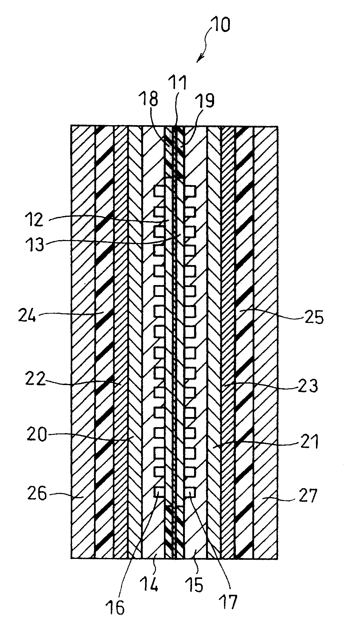
图1是本发明的一个具体实施方式的燃料电池的一个单元电池的纵向剖面示意图;Fig. 1 is a schematic longitudinal sectional view of a unit cell of a fuel cell according to a specific embodiment of the present invention;
图2是该单元电池主体部分放大的剖面图;以及FIG. 2 is an enlarged sectional view of the main body of the unit cell; and
图3是表示用以在电解质膜上形成疏水层的喷涂装置的结构示意图。Fig. 3 is a schematic diagram showing the structure of a spray coating device for forming a hydrophobic layer on an electrolyte membrane.
具体实施方式 Detailed ways
本发明的直接氧化燃料电池包括至少一个单元电池。该至少一个单元电池包括:阳极、阴极、介于该阳极和该阴极之间的氢离子传导聚合物电解质膜、带有用于向该阳极供给或从其中排出燃料的流通通道的阳极侧隔离层,以及带有向该阴极供给或从其中排出氧化剂气体的气体流通通道的阴极侧隔离层。疏水层形成在电解质膜的各个侧面上以围绕阳极或阴极。优选地,形成疏水层以围绕电极,从而使疏水层和电极之间没有间隙。电解质膜上可以存在一些未被疏水层覆盖的外部区域。The direct oxidation fuel cell of the present invention includes at least one unit cell. The at least one unit cell includes: an anode, a cathode, a hydrogen ion conducting polymer electrolyte membrane interposed between the anode and the cathode, an anode-side separator with a flow passage for supplying or discharging fuel to the anode, and a cathode-side separator having a gas flow channel for supplying or exhausting an oxidant gas to or from the cathode. A hydrophobic layer is formed on each side of the electrolyte membrane to surround the anode or cathode. Preferably, the hydrophobic layer is formed to surround the electrodes so that there is no gap between the hydrophobic layer and the electrodes. There may be some outer regions on the electrolyte membrane that are not covered by the hydrophobic layer.
疏水层优选至少包含疏水树脂细颗粒和疏水粘合材料。The hydrophobic layer preferably contains at least hydrophobic resin fine particles and a hydrophobic binding material.
使用这类材料能在电解质膜的表面上形成表面粗糙并且表面能非常低的疏水层。于是有可能有效地抑制水渗入到电解质膜中。Use of such materials enables the formation of a hydrophobic layer with a rough surface and very low surface energy on the surface of the electrolyte membrane. It is then possible to effectively suppress the infiltration of water into the electrolyte membrane.
疏水层中的疏水树脂细颗粒优选氟碳树脂细颗粒。The hydrophobic resin fine particles in the hydrophobic layer are preferably fluorocarbon resin fine particles.
氟碳树脂具有化学稳定的碳-氟键(C-F)。因此,用氟碳树脂作为疏水的细颗粒可形成一疏水表面,即,与其它分子相互作用微弱的表面。氟碳树脂的例子包括聚四氟乙烯树脂(PTFE)、四氟乙烯-六氟丙烯共聚物(FEP),聚氟乙烯树脂(PVF)、聚偏氟乙烯树脂(PVDF),以及四氟乙烯-全氟(烷基乙烯醚)共聚物(PFA)。Fluorocarbon resins have chemically stable carbon-fluorine bonds (C-F). Therefore, using a fluorocarbon resin as hydrophobic fine particles can form a hydrophobic surface, that is, a surface that interacts weakly with other molecules. Examples of fluorocarbon resins include polytetrafluoroethylene resin (PTFE), tetrafluoroethylene-hexafluoropropylene copolymer (FEP), polyvinyl fluoride resin (PVF), polyvinylidene fluoride resin (PVDF), and tetrafluoroethylene- Perfluoro(alkyl vinyl ether) copolymer (PFA).
疏水层中的疏水粘合材料优选氟碳树脂或硅树脂。The hydrophobic adhesive material in the hydrophobic layer is preferably fluorocarbon resin or silicone resin.
用氟碳树脂或硅树脂作为疏水粘合材料能在形成与电解质膜粘附良好的疏水层,同时不削弱其疏水性。对氟碳树脂没有特别限定,其可以是聚氟乙烯树脂、聚偏氟乙烯树脂等。硅树脂可以是纯的硅树脂,或者是在分子构架中具有硅氧烷键并在侧链中具有甲基的改性硅树脂。Using fluorocarbon resin or silicone resin as the hydrophobic binding material can form a hydrophobic layer that adheres well to the electrolyte membrane without weakening its hydrophobicity. The fluorocarbon resin is not particularly limited, and it may be polyvinyl fluoride resin, polyvinylidene fluoride resin, or the like. The silicone resin may be pure silicone resin, or a modified silicone resin having siloxane bonds in the molecular framework and methyl groups in the side chains.
本发明还提供了一种用以制造本发明的上述燃料电池的方法。The present invention also provides a method for manufacturing the above fuel cell of the present invention.
用以制造本发明的直接氧化燃料电池的第一种方法包括如下步骤:A first method for manufacturing the direct oxidation fuel cell of the present invention comprises the following steps:
(a)在电解质膜各个侧面上形成包含催化剂粒子和聚合物电解质的催化剂层,以获得膜催化剂层组件(membrane-catalyst layer assembly);(a) forming a catalyst layer comprising catalyst particles and a polymer electrolyte on each side of the electrolyte membrane to obtain a membrane-catalyst layer assembly;
(b)在电解质膜上形成疏水层以围绕各个催化剂层;(b) forming a hydrophobic layer on the electrolyte membrane to surround each catalyst layer;
(c)将带有疏水层的膜催化剂层组件浸入水中;以及(c) immersing the membrane catalyst layer assembly with the hydrophobic layer in water; and
(d)将扩散层粘结到各个催化剂层上。(d) Bonding the diffusion layer to each catalyst layer.
第一种制造方法中,在膜催化剂层组件发生水合作用之前,各个疏水层形成于其上没有形成催化剂层的电解质膜的区域上。于是这就有可能提高催化剂层和电解质膜中的氢离子传导率,同时不会引起诸如催化剂层在水合作用时发生分离或损坏之类的粘合问题。In the first manufacturing method, each hydrophobic layer is formed on the region of the electrolyte membrane on which the catalyst layer is not formed, before hydration of the membrane catalyst layer assembly occurs. This then makes it possible to increase the hydrogen ion conductivity in the catalyst layer and the electrolyte membrane without causing adhesion problems such as separation or damage of the catalyst layer upon hydration.
用以制造本发明的直接氧化燃料电池的第二种方法包括如下步骤:A second method for making the direct oxidation fuel cell of the present invention comprises the steps of:
(a)在电解质膜的各个侧面上形成疏水层,以围绕其上将形成催化剂层的预定区域;(a) forming a hydrophobic layer on each side of the electrolyte membrane so as to surround a predetermined region on which the catalyst layer will be formed;
(b)将带有疏水层的电解质膜浸入水中;(b) immersing the electrolyte membrane with the hydrophobic layer in water;
(c)在电解质膜的各个侧面的预定区域上形成包含催化剂粒子和聚合物电解质的催化剂层,以获得膜催化剂层组件;(c) forming a catalyst layer containing catalyst particles and a polymer electrolyte on a predetermined area on each side of the electrolyte membrane to obtain a membrane catalyst layer assembly;
(d)将膜催化剂层组件浸入水中;以及(d) immersing the membrane catalyst layer assembly in water; and
(e)将扩散层粘结到各个催化剂层上。(e) Bonding the diffusion layer to each catalyst layer.
第二种制造方法中,在制造膜催化剂层组件之前,各个疏水层形成于电解质膜上,接着发生水合作用。于是,朝向催化剂层的电解质膜部分能在其表面附近发生充分的水合作用,而不受未朝向催化剂层的电解质膜部分的溶胀和变形的影响。因此这有可能提高催化剂层和电解质膜之间的粘附力。此外,由于水合过程能刚好在膜催化剂层组件制成后进行,故有可能使因电解质膜和催化剂层中的水蒸发而引起的电解质组分结构变化减到最低程度。因此,能够缩短用以确保氢离子传导率的水合作用的时间。In the second manufacturing method, each hydrophobic layer is formed on the electrolyte membrane before the membrane catalyst layer assembly is manufactured, followed by hydration. Thus, the portion of the electrolyte membrane facing the catalyst layer can be sufficiently hydrated in the vicinity of its surface without being affected by swelling and deformation of the portion of the electrolyte membrane not facing the catalyst layer. This therefore makes it possible to improve the adhesion between the catalyst layer and the electrolyte membrane. In addition, since the hydration process can be performed just after the membrane catalyst layer assembly is fabricated, it is possible to minimize structural changes in the electrolyte components due to evaporation of water in the electrolyte membrane and catalyst layer. Therefore, the time for hydration to ensure hydrogen ion conductivity can be shortened.
在第一种和第二种制造方法的优选实施方式中,疏水层用湿涂法形成。In preferred embodiments of the first and second manufacturing methods, the hydrophobic layer is formed by wet coating.
疏水层能用湿涂法如喷涂法和刮涂法,以及干涂法如等离子气相沉积而形成。然而,考虑到维持电解质膜和催化剂层的水合状态,湿涂法是优选的。The hydrophobic layer can be formed by wet coating methods such as spray coating and blade coating, and dry coating methods such as plasma vapor deposition. However, the wet coating method is preferable in view of maintaining the hydration state of the electrolyte membrane and the catalyst layer.
在第一种和第二种制造方法的另一优选实施方式中,通过喷涂至少包含疏水树脂细颗粒和疏水粘合材料的浆料并将其干燥来形成疏水层。In another preferred embodiment of the first and second manufacturing methods, the hydrophobic layer is formed by spraying and drying a slurry containing at least hydrophobic resin fine particles and a hydrophobic binding material.
采用喷涂法使含疏水材料的小液滴薄而均匀地沉积在电解质膜的表面上。因此这有可能形成表面粗糙而且表面能非常低的疏水层,同时不削弱电解质膜的挠性。Small droplets containing hydrophobic materials are thinly and uniformly deposited on the surface of the electrolyte membrane by spraying. It is therefore possible to form a hydrophobic layer with a rough surface and a very low surface energy without impairing the flexibility of the electrolyte membrane.
如上所述,根据本发明,疏水层形成于电解质膜的各个侧面上以围绕电极。于是,水或有机燃料难以渗入到围绕电极的电解质膜部分中。因此,当MEA发生水合作用以确保氢离子传导率时或当供应有机燃料时,能够避免电解质膜发生急速溶胀或变形。其结果是,有可能解决电极与电解质膜之间粘附力弱的问题,如电极的外边缘分离或损坏的问题,并同时解决穿越电极和垫圈间的间隙的燃料增加的问题。因此,本发明能提供一种具有良好发电特性的直接氧化燃料电池,同时不降低其燃料的利用率。As described above, according to the present invention, the hydrophobic layer is formed on each side of the electrolyte membrane to surround the electrodes. Then, it is difficult for water or organic fuel to permeate into the electrolyte membrane portion surrounding the electrodes. Therefore, rapid swelling or deformation of the electrolyte membrane can be avoided when the MEA is hydrated to secure hydrogen ion conductivity or when an organic fuel is supplied. As a result, it is possible to solve the problem of weak adhesion between the electrode and the electrolyte membrane, such as the problem of separation or damage of the outer edge of the electrode, and at the same time solve the problem of increased fuel passing through the gap between the electrode and the gasket. Therefore, the present invention can provide a direct oxidation fuel cell having good power generation characteristics without reducing its fuel utilization rate.
现在结合附图,对本发明的实施方式进行描述。Embodiments of the present invention will now be described in conjunction with the accompanying drawings.
实施方式1Embodiment 1
图1是表示本发明的一个实施方式的燃料电池结构的纵向剖面示意图。在此实施例中,燃料电池由一个单元电池组成。单元电池10包括夹在阳极侧隔离层14与阴极侧隔离层15间的膜电极组件(MEA)。MEA包括氢离子传导电解质膜11以及夹着电解质膜11的阳极12和阴极13。阳极侧隔离层14带有用于向阳极侧供给并从其排出燃料的流通通道16。阴极侧隔离层15带有用于向阴极侧供给并从其排出氧化剂气体的气体流通通道17。垫圈18和19安装于阳极和阴极的外围以夹住电解质膜。FIG. 1 is a schematic longitudinal sectional view showing the structure of a fuel cell according to an embodiment of the present invention. In this embodiment, the fuel cell is composed of one unit cell. The
单元电池10还包括集电器板20和21、加热器板22和23、绝缘体板24和25,以及电池两个侧面上的底板26和27,用夹紧方法将这些组件牢固地固定在一起。The
图2显示了MEA的主体部分的结构。阳极12和阴极13分别包括与电解质膜11相接触的催化剂层33和34以及隔离层侧面上的扩散层35和36。在此实施例中,阳极和阴极位于电解质膜11的中心区,并且疏水层31和32分别形成于围绕阳极和阴极的电解质膜的外围区域。垫圈18和19设在疏水层上。Figure 2 shows the structure of the main part of the MEA.
电解质膜11可由任合氢离子传导率、耐热性及化学稳定性出色的材料制成,并对此类材料无特别限定。The
催化剂层33和34均是主要由聚合物电解质和载有催化剂金属或金属微粒的导电碳粒子组成的多孔薄膜。阳极催化剂层33的催化剂金属为以细颗粒形式存在的铂-钌(Pt-Ru)合金,而阴极催化剂层34的催化剂金属为以细颗粒形式存在的铂。聚合物电解质可以是任合氢离子传导率、耐热性及化学稳定性出色的材料,并对此材料无特别限定。Both catalyst layers 33 and 34 are porous thin films mainly composed of polymer electrolyte and conductive carbon particles carrying catalyst metal or metal fine particles. The catalyst metal of the
阳极扩散层35的基层可以是具有燃料扩散性、对发电生成的二氧化碳的可排出性和电子传导性的导电多孔材料,如碳纸或碳布。导电多孔基层可用常规方法进行疏水处理。此外,在催化剂层(33)上的导电多孔基层表面可以带有疏水的碳层。The base layer of the
阴极扩散层36的基层可以是具有空气扩散性、对发电生成的水的可排出性和电子传导性的导电多孔材料,如碳纸或碳布。导电多孔基层可用常规方法进行疏水处理。此外,在催化剂层(34)上的导电多孔基层的表面可以带有疏水的碳层。The base layer of the
疏水层31和32由主要包含疏水树脂细颗粒的疏水材料或疏水浆料和疏水粘合材料如氟碳树脂或硅树脂组成,其中疏水树脂例如是聚四氟乙烯树脂、四氟乙烯-六氟丙烯共聚物、聚氟乙烯树脂,聚偏氟乙烯树脂、或四氟乙烯-全氟(烷基乙烯醚)共聚物。形成这些层的优选示例方法包括喷涂疏水材料或浆料的方法,以及通过使用涂布机如刮片的湿涂法进行施涂的方法。The
特别地,采用喷涂法可使含疏水材料的小液滴薄而均匀地沉积在电解质膜的表面上。因此这有可能形成表面粗糙且表面能非常低的疏水层,同时不削弱电解质膜的挠性。In particular, small liquid droplets containing a hydrophobic material can be thinly and uniformly deposited on the surface of the electrolyte membrane by the spraying method. It is therefore possible to form a hydrophobic layer with a rough surface and a very low surface energy without impairing the flexibility of the electrolyte membrane.
此外,用喷涂法对其进行施涂的电解质膜的表面温度优选30~60℃。在此温度范围内,含疏水材料的小液滴能在涂覆面上沉积并干燥,此时包含在电解质膜中的水的蒸发受到抑制。于是有可能抑制疏水层中的微裂缝的产生。然而,如果电解质膜的表面温度超过60℃,包含在电解质膜中的水的蒸发速度变高,而这是不可取的。另一方面,如果电解质膜的表面温度低于30℃,浆料中的挥发性组分的蒸发速度则过低。于是,在一层形成后,大量的溶剂蒸发,从而促进微裂缝的产生,故这是不可取的。In addition, the surface temperature of the electrolyte membrane to which it is applied by the spray coating method is preferably 30 to 60°C. In this temperature range, small liquid droplets containing a hydrophobic material can be deposited on the coated surface and dried while the evaporation of the water contained in the electrolyte membrane is suppressed. It is then possible to suppress the generation of microcracks in the water-repellent layer. However, if the surface temperature of the electrolyte membrane exceeds 60° C., the evaporation rate of water contained in the electrolyte membrane becomes high, which is not preferable. On the other hand, if the surface temperature of the electrolyte membrane is lower than 30°C, the evaporation rate of the volatile components in the slurry is too low. Then, after one layer is formed, a large amount of solvent evaporates, thereby promoting the generation of microcracks, so this is not preferable.
隔离层14和15可以是任一具有气密性、电子导电性以及电化学稳定性的材料,并且该材料无特别的限定。此外,流通通道16和17的形状无特别限定。The isolation layers 14 and 15 can be any material with air tightness, electronic conductivity and electrochemical stability, and the material is not particularly limited. In addition, the shapes of the
图3是表示用以在电解质膜上形成本发明的疏水层31和32的喷涂装置结构示意图。喷涂装置40具有包含浆料42的槽41,浆料42是分散在介质中的疏水树脂细颗粒的均一分散体。槽中的浆料因搅拌器43的操作而恒定地流动,并且通过配有泵44的管子45供应给喷嘴46。此外,氮气通过管子48作为喷射气体从气缸47中供应给喷嘴46。Fig. 3 is a schematic diagram showing the construction of a spraying device for forming the
连接到传动器49上的喷嘴46,能以一给定的速度沿X轴和Y轴这两个方向移动。在喷涂浆料42时,喷嘴46在其上将形成疏水层的电解质膜50上移动,从而将浆料42均匀地涂在电解质膜50上。此时,电解质膜50用工作台51上的加热器52加热,使其表面温度为30~60℃。The
接下来用实施例和对照例对本发明进行详细说明,这不应看作是以任何方式对本发明进行限制。Next, the present invention will be described in detail with examples and comparative examples, which should not be construed as limiting the present invention in any way.
实施例1Example 1
将平均粒度均为

带有阳极催化剂层的片材和带有阴极催化剂层的片材被切成6cm×6cm大小。将电解质膜中心部分夹在两种片材中间,使得各催化剂层面向内设置。将这一组合体在82kg/cm2、130℃下热压3分钟。采用的电解质膜是全氟烃基磺酸的离子交换膜(Nafion112,购自E.I.Du Pontde Nemours & Company)。其后,将聚四氟乙烯片材从制得的组件中移出,以使阳极催化剂层和阴极催化剂层形成在电解质膜的中心部分。阳极催化剂层和阴极催化剂层中的铂催化剂的量均为2.2mg/cm2。The sheet with the anode catalyst layer and the sheet with the cathode catalyst layer were cut to a size of 6 cm x 6 cm. The central part of the electrolyte membrane is sandwiched between the two sheets, so that the catalyst layers face inwardly. This assembly was hot-pressed at 82 kg/cm 2 at 130°C for 3 minutes. The electrolyte membrane used was an ion exchange membrane of perfluoroalkyl sulfonic acid (Nafion 112, available from EI Du Pontde Nemours & Company). Thereafter, the polytetrafluoroethylene sheet was removed from the fabricated assembly so that an anode catalyst layer and a cathode catalyst layer were formed in the central portion of the electrolyte membrane. The amount of the platinum catalyst in both the anode catalyst layer and the cathode catalyst layer was 2.2 mg/cm 2 .
之后,通过稀释主要由聚四氟乙烯树脂细颗粒和硅树脂组成的超疏水(super-water-repellent)材料(HIREC450,购自NTT先进技术公司),制得用以形成疏水层的浆料。该浆料填充在图3所示喷涂装置40的槽42中。由于电解质膜的催化剂层上覆盖一保护性覆盖层,故浆料喷涂在电解质膜的暴露部分,即围绕催化剂层的周边部分。在喷涂过程中,电解质膜的表面温度为50℃。然后将浆料在室温下干燥约1小时以形成疏水层。通过这种方法,在电解质膜上未形成催化剂层的区域的各个侧面上形成15μm厚的疏水层。Thereafter, a slurry for forming a hydrophobic layer was prepared by diluting a super-water-repellent material (HIREC450, available from NTT Advanced Technology Co., Ltd.) mainly composed of polytetrafluoroethylene resin fine particles and silicone resin. The slurry is filled in the
将具有疏水层的膜催化剂层组件浸在70℃的去离子水中6小时。The membrane catalyst layer assembly with the hydrophobic layer was immersed in deionized water at 70°C for 6 hours.
随后,用Kimwipe S-200(购自Nippon Paper Crecia Co.,Ltd)除去膜催化剂层组件表面上的水。然后将6cm×6cm的扩散层设置在各个阳极催化剂层和阴极催化剂层上,并在41kg/cm2、130℃下热压2分钟。采用碳纸(TGP-H090,Toray工业公司)作为各个扩散层的基层,并且催化剂层侧面的碳纸表面上涂有15μm厚的疏水碳层。Subsequently, Kimwipe S-200 (available from Nippon Paper Crecia Co., Ltd.) was used to remove water on the surface of the membrane catalyst layer assembly. A 6 cm x 6 cm diffusion layer was then placed on each of the anode catalyst layer and the cathode catalyst layer, and hot-pressed at 41 kg/cm 2 at 130° C. for 2 minutes. Carbon paper (TGP-H090, Toray Industrial Co.) was used as the base layer of each diffusion layer, and a 15 μm thick hydrophobic carbon layer was coated on the surface of the carbon paper on the side of the catalyst layer.
此外,在41kg/cm2、135℃下热压阳极和阴极外围垫圈30分钟,以夹住电解质膜,形成MEA。In addition, the anode and cathode peripheral gaskets were hot-pressed at 41 kg/cm 2 at 135° C. for 30 minutes to sandwich the electrolyte membrane to form an MEA.
MEA被夹在隔离层、集电器板、加热器板、绝缘体板以及底板之间,其外尺寸为12cm×12cm,整个单元用夹紧棒条固定。每隔离层面积的夹紧压力为20kgf/cm2。阳极侧和阴极侧隔离层分别由4mm厚的浸满树脂的石墨板(G347B,购自Tokai Carbon有限公司)组成,该石墨板在面向阳极一侧或面向阴极一侧具有宽1.5mm、深1mm的弯曲流通通道。集电器板为镀金不锈钢板,底板为不锈钢板。The MEA is sandwiched between the spacer, collector plate, heater plate, insulator plate, and base plate, with an outer dimension of 12 cm x 12 cm, and the entire unit is fixed with clamping rods. The clamping pressure per spacer area is 20 kgf/cm 2 . The anode-side and cathode-side separators consisted of a 4 mm thick resin-impregnated graphite plate (G347B, purchased from Tokai Carbon Co., Ltd.) with a width of 1.5 mm and a depth of 1 mm on the side facing the anode or the side facing the cathode. curved circulation channel. The current collector plate is a gold-plated stainless steel plate, and the bottom plate is a stainless steel plate.
通过该方法制得燃料电池A。A fuel cell A was produced by this method.
实施例2Example 2
用与实施例1相同的制造方法制得燃料电池B,所不同的只是,采用图3中的装置,喷涂通过将去离子水加到四氟乙烯-六氟丙烯共聚物树脂(ND-10E,购自Daikin工业公司)的分散体中而制得的稀释溶液(40wt%的FEP含量),以形成疏水层。Fuel cell B was prepared in the same manufacturing method as in Example 1, except that the device in Fig. 3 was used for spray coating by adding deionized water to tetrafluoroethylene-hexafluoropropylene copolymer resin (ND-10E, A diluted solution (40 wt% FEP content) was prepared in a dispersion (available from Daikin Industries Co., Ltd.) to form a hydrophobic layer.
实施例3Example 3
用与实施例1相同的制造方法制得燃料电池C,所不同的只是,主要由磺化聚醚酮醚(PEEK)组成的碳氢化合物型聚合物电解质膜(厚度为60μm)用作其电解质膜,并且在形成疏水层后,将膜催化剂层组件浸入去离子水中12小时。A fuel cell C was produced in the same manufacturing method as in Example 1, except that a hydrocarbon-type polymer electrolyte membrane (60 μm in thickness) mainly composed of sulfonated polyetheretherketone (PEEK) was used as its electrolyte membrane, and after forming the hydrophobic layer, the membrane catalyst layer assembly was immersed in deionized water for 12 hours.
实施例4Example 4
用与实施例1相同的制造方法制得燃料电池D,所不同的只是,主要由磺化聚醚酮醚(PEEK)组成的碳氢化合物型聚合物电解质膜(厚度为60μm)用作其电解质膜,以及增加了在将催化剂层热压到电解质膜上之前的下述步骤:在除了其上将形成催化剂层区域以外的电解质膜上,形成疏水层,并且将具有疏水层的电解质膜浸入70℃的去离子水中1小时。A fuel cell D was produced in the same manufacturing method as in Example 1, except that a hydrocarbon-type polymer electrolyte membrane (60 μm in thickness) mainly composed of sulfonated polyetherketone ether (PEEK) was used as its electrolyte Membrane, and the following step is added before hot pressing the catalyst layer onto the electrolyte membrane: On the electrolyte membrane except the area where the catalyst layer will be formed, a hydrophobic layer is formed, and the electrolyte membrane having the hydrophobic layer is immersed in 70 °C deionized water for 1 hour.
对照例1Comparative example 1
用与实施例1相同的制造方法制得燃料电池E,所不同的只是,没有在电解质膜上形成疏水层。A fuel cell E was produced in the same manufacturing method as in Example 1, except that no hydrophobic layer was formed on the electrolyte membrane.
对照例2Comparative example 2
用与实施例2相同的制造方法制得燃料电池F,所不同的只是,没有在电解质膜上形成疏水层。A fuel cell F was produced in the same manufacturing method as in Example 2, except that no hydrophobic layer was formed on the electrolyte membrane.
用如下评估测试方法对实施例的燃料电池A~D以及对照例的燃料电池E和F进行评估。表1为评估结果。The fuel cells A to D of Examples and the fuel cells E and F of Comparative Examples were evaluated by the following evaluation test methods. Table 1 is the evaluation result.
表1Table 1
(1)与水的接触角(1) Contact angle with water
将去离子水(表面张力72.8mN/m)滴到将与垫圈接触的电解质膜部分的表面上。在50毫秒之后测量其接触角。Deionized water (surface tension 72.8 mN/m) was dropped onto the surface of the electrolyte membrane portion to be in contact with the gasket. The contact angle thereof was measured after 50 milliseconds.
(2)电流-电压特性1(2) Current-voltage characteristics 1
2M的甲醇水溶液以0.4cc/min的流量供给到阳极,空气则以0.2L/min的流量供给到阴极。当电池温度保持在60℃时,以电流密度为150mA/cm2持续发电。在电池发电8小时后,测量其有效电压。A 2M aqueous methanol solution was supplied to the anode at a flow rate of 0.4 cc/min, and air was supplied to the cathode at a flow rate of 0.2 L/min. When the battery temperature was maintained at 60°C, power generation was continued at a current density of 150mA/cm 2 . After the battery generates electricity for 8 hours, measure its effective voltage.
(3)电流-电压特性2(3) Current-voltage characteristics 2
4M的甲醇水溶液以0.2cc/min的流量供给到阳极,空气则以0.2L/min的流量供给到阴极。电池温度保持在60℃,持续发电时的电流密度为150mA/cm2。在电池发电8小时后,测量其有效电压。A 4M aqueous methanol solution was supplied to the anode at a flow rate of 0.2 cc/min, and air was supplied to the cathode at a flow rate of 0.2 L/min. The battery temperature was kept at 60° C., and the current density was 150 mA/cm 2 during continuous power generation. After the battery generates electricity for 8 hours, measure its effective voltage.
表1清楚说明如下问题。对于燃料电池A~D而言,疏水层形成于其上没有形成催化剂层的电解质膜区域上。于是,水或甲醇水溶液难以渗入到电解质膜的这些区域中。因此,当MEA发生水合作用以确保氢离子传导率时或当将甲醇水溶液供应给电池用于发电时,避免了电解质膜发生急速溶胀或变形。其结果是,有可能解决电极与电解质膜之间粘附力弱的问题,如电极的外边缘分离或损坏的问题,并同时解决穿越电极和垫圈间的间隙的甲醇增加的问题。此外,燃料电池A~D即使在于低空气流速下供应高浓度甲醇的运行条件下,仍表现出良好的发电特性。就燃料电池D而言,特别是在制得膜催化剂层组件之前,疏水层形成于电解质膜上,接着发生水合作用。于是,其上将形成催化剂层的电解质膜部分能在其表面附近发生充分的水合作用,而不受电解质膜周边部分溶胀和变形的影响。其结果是,催化剂层与电解质膜的粘附力进一步得到增强,并且其发电特性得到显著地提高。Table 1 clearly illustrates the following issues. For the fuel cells A to D, the water-repellent layer was formed on the region of the electrolyte membrane on which the catalyst layer was not formed. Then, it is difficult for water or methanol aqueous solution to penetrate into these regions of the electrolyte membrane. Therefore, rapid swelling or deformation of the electrolyte membrane is avoided when the MEA is hydrated to secure hydrogen ion conductivity or when methanol aqueous solution is supplied to the battery for power generation. As a result, it is possible to solve the problem of weak adhesion between the electrode and the electrolyte membrane, such as the problem of separation or damage of the outer edge of the electrode, and at the same time solve the problem of the increase of methanol passing through the gap between the electrode and the gasket. In addition, the fuel cells AD exhibited good power generation characteristics even under operating conditions in which a high concentration of methanol was supplied at a low air flow rate. In the case of fuel cell D, in particular, before the membrane catalyst layer assembly is fabricated, a hydrophobic layer is formed on the electrolyte membrane, followed by hydration. Thus, the portion of the electrolyte membrane on which the catalyst layer will be formed can be sufficiently hydrated in the vicinity of its surface without being affected by swelling and deformation of the peripheral portion of the electrolyte membrane. As a result, the adhesion of the catalyst layer to the electrolyte membrane is further enhanced, and its power generation characteristics are remarkably improved.
与此相反,就燃料电池E和F而言,没有在围绕催化剂层的电解质膜周边部分上形成疏水层。于是,在MEA发生水合作用时以及将甲醇水溶液供应给电池用于发电时,电解质膜周边部分未能免于发生溶胀和变形,从而导致电极与电解质膜间的粘附力下降以及穿越电极和垫圈间的间隙的甲醇增加。可能因此,当供给高浓度甲醇时,电池的发电特性变差。In contrast, with the fuel cells E and F, no water-repellent layer was formed on the peripheral portion of the electrolyte membrane surrounding the catalyst layer. Then, when the MEA is hydrated and when the methanol aqueous solution is supplied to the battery for power generation, the peripheral part of the electrolyte membrane is not protected from swelling and deformation, resulting in a decrease in the adhesion between the electrodes and the electrolyte membrane and passing through the electrodes and gaskets. The interstitial methanol increases. Possibly because of this, when high-concentration methanol is supplied, the power generation characteristics of the battery deteriorate.
本发明的燃料电池可直接使用燃料,如甲醇、二甲醚等,而无须将其转变为氢,因此该类电池可用作便携式小型电子装置的电源,如便携式电话、掌上电脑(PDA)、笔记本个人电脑以及摄像机等。它还可用作电车等的电源。The fuel cell of the present invention can directly use fuel, such as methanol, dimethyl ether, etc., without converting it into hydrogen, so this type of battery can be used as a power source for portable small electronic devices, such as cellular phones, palmtop computers (PDA), Notebook personal computer and video camera etc. It can also be used as a power source for trams, etc.
尽管本发明已按照最优方案进行了描述,但应当理解,这样的公开并不是一种限制。对那些与本发明相关的技术熟练人员来说,在了解了上述公开内容后,无疑可对本发明进行各种变更和修改。因此,所附加的权利要求应被解释为覆盖了所有落在本发明的宗旨和范围内的变化。While this invention has been described in terms of its preferred form, it is to be understood that such disclosure is not limiting. Various changes and modifications of the invention will no doubt become apparent to those skilled in the art to which the invention pertains after having the above disclosure. Accordingly, the appended claims should be construed to cover all changes which fall within the spirit and scope of the invention.
Claims (13)
Applications Claiming Priority (2)
| Application Number | Priority Date | Filing Date | Title |
|---|---|---|---|
| JP2006078404 | 2006-03-22 | ||
| JP2006078404 | 2006-03-22 |
Publications (2)
| Publication Number | Publication Date |
|---|---|
| CN101022172A CN101022172A (en) | 2007-08-22 |
| CN100511806C true CN100511806C (en) | 2009-07-08 |
Family
ID=38533850
Family Applications (1)
| Application Number | Title | Priority Date | Filing Date |
|---|---|---|---|
| CNB2007100886879A Expired - Fee Related CN100511806C (en) | 2006-03-22 | 2007-03-15 | Direct oxidation fuel cell and method for making same |
Country Status (4)
| Country | Link |
|---|---|
| US (1) | US20070224486A1 (en) |
| JP (1) | JP2007287663A (en) |
| KR (1) | KR100832213B1 (en) |
| CN (1) | CN100511806C (en) |
Families Citing this family (6)
| Publication number | Priority date | Publication date | Assignee | Title |
|---|---|---|---|---|
| JP5388639B2 (en) * | 2008-03-19 | 2014-01-15 | キヤノン株式会社 | Catalyst layer of polymer electrolyte fuel cell, membrane electrode assembly, and fuel cell |
| JP5388691B2 (en) * | 2008-05-23 | 2014-01-15 | キヤノン株式会社 | Method for producing catalyst layer and membrane electrode assembly |
| JP2010170892A (en) * | 2009-01-23 | 2010-08-05 | Panasonic Corp | Fuel cell |
| WO2012001061A1 (en) * | 2010-06-29 | 2012-01-05 | Vito Nv | Gas diffusion electrode, method of producing same, membrane electrode assembly comprising same and method of producing membrane electrode assembly comprising same |
| JP6102624B2 (en) * | 2013-08-08 | 2017-03-29 | エヌ・イーケムキャット株式会社 | Method for manufacturing disk electrode for electrochemical measurement |
| JP6064884B2 (en) * | 2013-12-10 | 2017-01-25 | トヨタ自動車株式会社 | Power generator |
Family Cites Families (4)
| Publication number | Priority date | Publication date | Assignee | Title |
|---|---|---|---|---|
| KR100446609B1 (en) * | 2000-03-17 | 2004-09-04 | 삼성전자주식회사 | Proton exchange membrane fuel cell and monopolar cell pack of direct methanol fuel cell |
| US7700211B2 (en) * | 2002-04-17 | 2010-04-20 | Nec Corporation | Fuel cell, fuel cell electrode and method for fabricating the same |
| US7195690B2 (en) * | 2003-05-28 | 2007-03-27 | 3M Innovative Properties Company | Roll-good fuel cell fabrication processes, equipment, and articles produced from same |
| US7344796B2 (en) * | 2004-02-18 | 2008-03-18 | Freudenberg-Nok General Partnership | Fluoroelastomer gasket compositions |
-
2007
- 2007-02-27 JP JP2007047296A patent/JP2007287663A/en not_active Withdrawn
- 2007-03-15 CN CNB2007100886879A patent/CN100511806C/en not_active Expired - Fee Related
- 2007-03-21 US US11/688,953 patent/US20070224486A1/en not_active Abandoned
- 2007-03-22 KR KR1020070028054A patent/KR100832213B1/en not_active Expired - Fee Related
Also Published As
| Publication number | Publication date |
|---|---|
| KR100832213B1 (en) | 2008-05-23 |
| CN101022172A (en) | 2007-08-22 |
| US20070224486A1 (en) | 2007-09-27 |
| JP2007287663A (en) | 2007-11-01 |
| KR20070095831A (en) | 2007-10-01 |
Similar Documents
| Publication | Publication Date | Title |
|---|---|---|
| CN103563143B (en) | Gas Diffusion Layers for Fuel Cells | |
| US8105732B2 (en) | Direct oxidation fuel cell | |
| US7964323B2 (en) | Direct oxidation fuel cell | |
| US20110244359A1 (en) | Membrane electrode assembly for fuel cell and fuel cell using the same | |
| JP5532630B2 (en) | Membrane electrode assembly, method for producing the same, and polymer electrolyte fuel cell | |
| KR20110043908A (en) | Method for manufacturing membrane electrode assembly for polymer electrolyte fuel cell | |
| JP5013740B2 (en) | Hydrophobic catalyst layer of polymer electrolyte fuel cell and method for producing the same, polymer electrolyte fuel cell and method for producing the same | |
| CN100511806C (en) | Direct oxidation fuel cell and method for making same | |
| US8283089B2 (en) | Direct oxidation fuel cell | |
| CN100379069C (en) | Direct Methanol Fuel Cell | |
| US20130164650A1 (en) | Membrane electrode assembly for direct oxidation fuel cell and direct oxidation fuel cell using the same | |
| CN100508266C (en) | Membrane electrode unit | |
| US20070178367A1 (en) | Direct oxidation fuel cell and method for operating direct oxidation fuel cell system | |
| KR100779820B1 (en) | Direct oxidation fuel cell and manufacturing method therefor | |
| KR100773669B1 (en) | Direct-type fuel cell and direct-type fuel cell system | |
| JP5153130B2 (en) | Membrane electrode assembly | |
| JP5326458B2 (en) | Membrane electrode assembly, method for producing the same, and polymer electrolyte fuel cell | |
| JP2010257669A (en) | Membrane electrode assembly, method for producing the same, and polymer electrolyte fuel cell | |
| JP2010170895A (en) | Method and device for manufacturing membrane electrode assembly | |
| JP5439946B2 (en) | Membrane electrode assembly, method for producing the same, and polymer electrolyte fuel cell | |
| JP2017091716A (en) | Membrane-electrode assembly | |
| KR101093708B1 (en) | Fuel cell electrode and fuel cell comprising same | |
| US8399144B2 (en) | Membrane-electrode assembly for direct oxidation fuel cell and direct oxidation fuel cell | |
| KR20250040174A (en) | Polymer electrolyte membrane fuel cell comprising a bipolar plate without flow channels | |
| US20100248074A1 (en) | Membrane electrode assembly for direct oxidation fuel cell and direct oxidation fuel cell including the same |
Legal Events
| Date | Code | Title | Description |
|---|---|---|---|
| C06 | Publication | ||
| PB01 | Publication | ||
| C10 | Entry into substantive examination | ||
| SE01 | Entry into force of request for substantive examination | ||
| C14 | Grant of patent or utility model | ||
| GR01 | Patent grant | ||
| C17 | Cessation of patent right | ||
| CF01 | Termination of patent right due to non-payment of annual fee |
Granted publication date: 20090708 Termination date: 20110315 |