CN100519309C - Vehicle body front structure - Google Patents
Vehicle body front structure Download PDFInfo
- Publication number
- CN100519309C CN100519309C CNB2006800016179A CN200680001617A CN100519309C CN 100519309 C CN100519309 C CN 100519309C CN B2006800016179 A CNB2006800016179 A CN B2006800016179A CN 200680001617 A CN200680001617 A CN 200680001617A CN 100519309 C CN100519309 C CN 100519309C
- Authority
- CN
- China
- Prior art keywords
- vehicle body
- fixing frame
- vehicle
- radiator
- radiator fixing
- Prior art date
- Legal status (The legal status is an assumption and is not a legal conclusion. Google has not performed a legal analysis and makes no representation as to the accuracy of the status listed.)
- Expired - Fee Related
Links
Images




Classifications
-
- B—PERFORMING OPERATIONS; TRANSPORTING
- B62—LAND VEHICLES FOR TRAVELLING OTHERWISE THAN ON RAILS
- B62D—MOTOR VEHICLES; TRAILERS
- B62D25/00—Superstructure or monocoque structure sub-units; Parts or details thereof not otherwise provided for
- B62D25/08—Front or rear portions
- B62D25/082—Engine compartments
-
- B—PERFORMING OPERATIONS; TRANSPORTING
- B62—LAND VEHICLES FOR TRAVELLING OTHERWISE THAN ON RAILS
- B62D—MOTOR VEHICLES; TRAILERS
- B62D21/00—Understructures, i.e. chassis frame on which a vehicle body may be mounted
- B62D21/15—Understructures, i.e. chassis frame on which a vehicle body may be mounted having impact absorbing means, e.g. a frame designed to permanently or temporarily change shape or dimension upon impact with another body
- B62D21/152—Front or rear frames
Landscapes
- Engineering & Computer Science (AREA)
- Chemical & Material Sciences (AREA)
- Combustion & Propulsion (AREA)
- Transportation (AREA)
- Mechanical Engineering (AREA)
- Body Structure For Vehicles (AREA)
Abstract
Description
技术领域 technical field
本发明涉及一种将一对车身前柱作为骨架的一部分,该车身前柱配置于车辆的车宽方向两侧且形成车辆的客舱的前部的车身前部结构。The present invention relates to a vehicle body front structure in which a pair of vehicle body front pillars are arranged on both sides in the vehicle width direction of a vehicle and form a front portion of a passenger compartment of the vehicle, as a part of a frame.
背景技术 Background technique
以往,在乘用车等的各种车辆的车身前部结构中,采用了用于吸收与其他车辆之间的碰撞时的冲击的结构。作为这种车身前部结构,已知有如下结构(例如参照日本国特开平11-43071号公报),即:利用构成发动机室的外框上部的车身围板上骨架(apron upper member),从车宽方向将支撑散热器的周缘部的散热器固定框的上端部支撑。Conventionally, structures for absorbing shocks at the time of collisions with other vehicles have been employed in vehicle body front structures of various vehicles such as passenger cars. As such a vehicle body front structure, there is known a structure (for example, refer to Japanese Patent Application Laid-Open No. 11-43071 ) in which an apron upper member constituting the upper part of the outer frame of the engine compartment is The upper end of the radiator fixing frame that supports the peripheral edge of the radiator is supported in the vehicle width direction.
为此,近年来,要求使碰撞载荷分散。而且要求,与上述公开专利公报中记载的以往技术相比,更有效地分散车辆前部的碰撞载荷。For this reason, in recent years, it is required to disperse the collision load. Furthermore, it is required to more effectively disperse the collision load at the front of the vehicle than the conventional technology described in the above-mentioned laid-open patent publication.
发明内容 Contents of the invention
本发明是为了解决这样的课题而完成的,其目的在于提供一种车身前部结构,可以有效地分散作用于车辆前部的碰撞载荷。The present invention has been made to solve such problems, and an object of the present invention is to provide a vehicle body front structure capable of effectively distributing collision loads acting on the vehicle front.
基于本发明的车身前部结构,将一对车身前柱作为骨架的一部分,该车身前柱配置于车辆的车宽方向两侧且形成车辆的客舱的前部,该车身前部结构的特征在于,具备:散热器固定框,其支撑散热器;一对第一散热器固定框支撑部件,其从车宽方向两侧对散热器固定框的支撑散热器上部的部分进行支撑,并与车身前柱连结;一对第二散热器固定框支撑部件,其配置于比一对第一散热器固定框支撑部件更靠车宽方向的内侧,且从后方对支撑散热器上部的散热器固定框的后面部分进行支撑,并与车身骨架连结。According to the vehicle body front structure of the present invention, a pair of vehicle body front pillars are used as a part of the skeleton. The vehicle body front pillars are arranged on both sides in the vehicle width direction of the vehicle and form the front of the vehicle passenger compartment. The vehicle body front structure is characterized in that , comprising: a radiator fixing frame, which supports the radiator; a pair of first radiator fixing frame support members, which support the radiator upper part of the radiator fixing frame from both sides in the vehicle width direction, and are connected to the front of the vehicle body Column connection; a pair of second radiator fixing frame support members, which are arranged on the inner side in the vehicle width direction than the pair of first radiator fixing frame support members, and support the radiator fixing frame on the upper part of the radiator from the rear. The rear part is supported and connected to the body frame.
根据本发明涉及的车身前部结构,在车辆前部配置的散热器固定框的支撑散热器上部的部分,通过从车宽方向的两侧进行支撑的一对第一散热器固定框支撑部件、和配置于比该一对第一散热器固定框支撑部件更靠车宽方向内侧且从后方进行支撑的第二散热器固定框支撑部件,与车身骨架连结。因此,在车辆碰撞时,针对散热器固定框的支撑散热器上部的部分的碰撞载荷,通过第一散热器固定框支撑部件、和配置于该第一散热器固定框支撑部件的车宽方向内侧的第二散热器固定框支撑部件,被传递到车身骨架且被有效地分散。另外,由于配置于比第一散热器固定框支撑部件更靠车宽方向内侧的第二散热器固定框支撑部件,支撑点距离变短,作用于散热器固定框的支撑散热器上部的部分的弯曲力矩减少,因此,与以往相比,可以承受更高的碰撞载荷。According to the vehicle body front structure according to the present invention, the portion of the radiator fixing frame disposed at the vehicle front that supports the upper portion of the radiator is supported by the pair of first radiator fixing frame support members from both sides in the vehicle width direction, The second radiator fixing frame supporting member disposed on the inside of the pair of first radiator fixing frame supporting members in the vehicle width direction and supported from the rear is connected to the vehicle body frame. Therefore, when the vehicle collides, the collision load on the portion of the radiator fixing frame that supports the upper portion of the radiator passes through the first radiator fixing frame supporting member and the inner side of the first radiator fixing frame supporting member in the vehicle width direction. The second radiator fixing frame support member, is transferred to the body frame and is effectively distributed. In addition, since the second radiator fixing frame supporting member is arranged on the inner side in the vehicle width direction than the first radiator fixing frame supporting member, the distance between the supporting points is shortened, and the force acting on the part of the radiator fixing frame supporting the upper part of the radiator is shortened. Bending moments are reduced, so higher crash loads can be accommodated than ever before.
这里,若具备将一对车身前柱的前部彼此连结的车身前围部,且第二散热器固定框支撑部件与车身前围部连结,则针对散热器固定框的支撑散热器上部的部分的碰撞载荷,通过第二散热器固定框支撑部件被传递到车身前围部,且被有效地分散到车身骨架。Here, if the front part of the pair of front pillars of the vehicle body is provided, and the second radiator fixing frame support member is connected to the front part of the vehicle body, the radiator fixing frame supports the upper part of the radiator. The collision load is transmitted to the vehicle body cowl through the second radiator fixing frame support member, and is effectively dispersed to the vehicle body frame.
另外,也可以构成为,具备车身前围支撑部件,该车身前围支撑部件将车身前围部的支撑第二散热器固定框支撑部件的部分与车身前柱连结。如果是这样的构成,则针对散热器固定框的支撑散热器上部的部分的碰撞载荷,通过第二散热器固定框支撑部件被传递到车身前围部,并通过车身前围支撑部件被传递到车身前柱,且有效地被分散到车身骨架。In addition, it may be configured to include a cowl support member that connects a portion of the vehicle body cowl portion that supports the second radiator fixing frame support member to the vehicle body front pillar. With such a configuration, the collision load on the portion of the radiator fixing frame that supports the upper part of the radiator is transmitted to the vehicle body cowl through the second radiator fixing frame support member, and is transmitted to the vehicle body cowl support member through the vehicle body cowl support member. The front pillars of the body are effectively distributed to the body frame.
另外,如果具备:车身前围部,其将一对车身前柱的前部彼此连结;发动机挡板,其与该车身前围部连结且构成客舱的前壁,并且第二散热器固定框支撑部件与发动机挡板连结,则针对散热器固定框的支撑散热器上部的部分的碰撞载荷,通过第二散热器固定框支撑部件被传递到发动机挡板,且被有效地分散到车身骨架。In addition, if provided with: a front part of the vehicle body, which connects the front parts of the pair of front pillars of the vehicle body; When the part is connected to the engine baffle, the collision load on the portion of the radiator fixing frame that supports the upper portion of the radiator is transmitted to the engine baffle through the second radiator fixing frame support member, and is effectively distributed to the vehicle body frame.
也可以构成为,具备发动机挡板支撑部件,该发动机挡板支撑部件将发动机挡板中的连结第二散热器固定框支撑部件的部分与车身前围部连结。如果是这样的构成,则针对散热器固定框的支撑散热器上部的部分的碰撞载荷,通过第二散热器固定框支撑部件被传递到发动机挡板,并通过发动机挡板支撑部件被传递到车身前柱,且有效地被分散到车身骨架。It may be configured to include an engine fender support member that connects a portion of the engine fender to which the second radiator fixing frame support member is connected, and the vehicle body cowl. With such a configuration, the collision load on the portion of the radiator fixing frame that supports the upper portion of the radiator is transmitted to the engine fender through the second radiator fixing frame support member, and is transmitted to the vehicle body through the engine fender support member. The front pillars, and are effectively distributed to the body frame.
另外,如果第二散热器固定框支撑部件,通过在车辆的前后方向上配置于散热器固定框和车身前围部之间的其他的部件,与车身骨架连结,则可以有效地起到上述作用的同时,可以将构成第二散热器固定框支撑部件的各个部件的长度缩短,与以往相比,可以承受更大的载荷。另外,提高第二散热器固定框支撑部件的配置的自由度。In addition, if the second radiator fixing frame supporting member is connected to the vehicle body frame through other members arranged between the radiator fixing frame and the vehicle body front wall in the front-rear direction of the vehicle, the above-mentioned functions can be effectively performed. At the same time, the length of each part constituting the support part of the second radiator fixing frame can be shortened, and it can withstand a larger load than before. In addition, the degree of freedom in the arrangement of the second radiator fixing frame support member is improved.
另外,如果其他的部件,是在车身侧对悬架中所使用的减振器进行支撑的悬架支撑罩,则针对散热器固定框的支撑散热器上部的部分的碰撞载荷,通过第二散热器固定框支撑部件和悬架支撑罩被传递,且有效地被分散到车身骨架,而且可以将构成第二散热器固定框支撑部件的各个部件的长度缩短,与以往相比,可以承受更大的载荷。另外,提高第二散热器固定框支撑部件的配置的自由度。In addition, if the other component is the suspension support cover that supports the shock absorber used in the suspension on the side of the vehicle body, the impact load of the part supporting the upper part of the radiator of the radiator fixing frame is transmitted through the second radiator. The radiator fixing frame support member and the suspension support cover are transferred and effectively distributed to the vehicle body frame, and the length of each part constituting the second radiator fixing frame support member can be shortened, which can withstand a larger load than before. load. In addition, the degree of freedom in the arrangement of the second radiator fixing frame support member is improved.
另外,基于本发明的车身前部结构,将一对车身前柱和地板通道作为骨架的一部分,该一对车身前柱配置在车辆的车宽方向两侧且形成车辆的客舱的前部,该地板通道形成在客舱的下面且在车辆前后方向上延伸,该车身前部结构的特征在于,具备:散热器固定框,其支撑散热器;一对第一散热器固定框支撑部件,其从车宽方向两侧对散热器固定框的支撑散热器上部的部分进行支撑,并与车身前柱连结;一对第二散热器固定框支撑部件,其在车宽方向上,配置于比一对第一散热器固定框支撑部件更靠内侧,且在车辆的前后方向上,配置在散热器固定框的支撑散热器上部的部分和地板通道之间,第二散热器固定框支撑部件,将发动机介于其间而被配置。In addition, based on the vehicle body front structure of the present invention, a pair of vehicle body front pillars and a floor tunnel are used as a part of the frame, and the pair of vehicle body front pillars are arranged on both sides in the vehicle width direction of the vehicle and form the front of the passenger compartment of the vehicle. The floor tunnel is formed under the passenger compartment and extends in the front-rear direction of the vehicle. The front structure of the vehicle body is characterized in that it includes: a radiator fixing frame supporting the radiator; a pair of first radiator fixing frame support members extending from the vehicle body. The two sides in the width direction support the part of the radiator fixing frame supporting the upper part of the radiator, and are connected to the front pillar of the vehicle body; a pair of second radiator fixing frame support members are arranged on the side of the pair of first radiator fixing frame support parts in the vehicle width direction. A radiator fixing frame supporting part is closer to the inner side, and is disposed between the part of the radiator fixing frame supporting the upper part of the radiator and the floor passage in the front-rear direction of the vehicle, and the second radiator fixing frame supporting part connects the engine configured in between.
根据这样的车身前部结构,针对散热器固定框的支撑散热器上部的部分的碰撞载荷,通过第一散热器固定框支撑部件和第二散热器固定框支撑部件及发动机被传递,且被有效地分散到车身骨架,并且,可以将构成第二散热器固定框支撑部件的各个部件的长度缩短,与以往相比,可以承受更大的载荷。另外,提高第二散热器固定框支撑部件的配置的自由度。另外,通过配置于比第一散热器固定框支撑部件更靠车宽方向内侧的第二散热器固定框支撑部件,支撑点距离变短,作用于散热器固定框的支撑散热器上部的部分的弯曲力矩减少,因此,与以往相比,可以承受更高的碰撞载荷。According to such a front structure of the vehicle body, the collision load to the portion of the radiator fixing frame that supports the upper part of the radiator is transmitted through the first radiator fixing frame supporting member, the second radiator fixing frame supporting member and the engine, and is effectively Distributed to the vehicle body frame, and the length of each member constituting the second radiator fixing frame support member can be shortened, so that it can bear a larger load than before. In addition, the degree of freedom in the arrangement of the second radiator fixing frame support member is improved. In addition, by disposing the second radiator fixing frame supporting member on the inner side in the vehicle width direction than the first radiator fixing frame supporting member, the distance between the supporting points is shortened, and the force acting on the part of the radiator fixing frame supporting the upper part of the radiator is shortened. Bending moments are reduced, so higher crash loads can be accommodated than ever before.
附图说明 Description of drawings
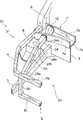
图1是从前方侧表示本发明的第1实施方式涉及的车身前部结构的立体图。FIG. 1 is a perspective view showing a front structure of a vehicle body according to a first embodiment of the present invention from the front side.
图2是表示图1所示的车身前部结构的俯视图。FIG. 2 is a plan view showing the front structure of the vehicle body shown in FIG. 1 .
图3是从前方侧表示本发明的第2实施方式涉及的车身前部结构的立体图。FIG. 3 is a perspective view showing a vehicle body front structure according to a second embodiment of the present invention from the front side.
图4是表示图3所示的车身前部结构的俯视图。Fig. 4 is a plan view showing the structure of the front part of the vehicle body shown in Fig. 3 .
图5是表示本发明的第3实施方式涉及的车身前部结构的俯视图。FIG. 5 is a plan view showing a vehicle body front structure according to a third embodiment of the present invention.
图6是从前方侧表示本发明的第4实施方式涉及的车身前部结构的立体图。FIG. 6 is a perspective view showing a vehicle body front structure according to a fourth embodiment of the present invention from the front side.
图7是从后方侧表示图6的车身前部结构的立体图。Fig. 7 is a perspective view showing the front structure of the vehicle body in Fig. 6 from the rear side.
图8是从后方侧表示本发明的第5实施方式涉及的车身前部结构的立体图。FIG. 8 is a perspective view showing a vehicle body front structure according to a fifth embodiment of the present invention from the rear side.
具体实施方式 Detailed ways
以下,参照附图对本发明的车身前部结构的优选实施方式进行说明。图1是从前方侧表示本发明的第1实施方式涉及的车身前部结构的立体图。图2是表示图1所示的车身前部结构的俯视图。此外,在附图的说明中,对相同或相当要素标以相同的符号,省略重复的说明。另外,在本说明书中,将车辆向前直行前进时的前方方向定义为“前方”,使用表示“前”“后”“左”“右”等方向的词。Hereinafter, preferred embodiments of the vehicle body front portion structure of the present invention will be described with reference to the drawings. FIG. 1 is a perspective view showing a front structure of a vehicle body according to a first embodiment of the present invention from the front side. FIG. 2 is a plan view showing the front structure of the vehicle body shown in FIG. 1 . In addition, in the description of the drawings, the same reference numerals are assigned to the same or corresponding elements, and overlapping descriptions will be omitted. In addition, in this specification, the front direction when a vehicle travels straight forward is defined as "front", and words indicating directions such as "front", "rear", "left", and "right" are used.
图1及图2所示的车身前部结构1,例如是乘用车等的车辆2的车身前部结构。车辆2在前部具备发动机室2a,在该发动机室2a的后方,隔着作为隔壁的发动机挡板3形成有客舱。此外,在图1中只图示了右侧。The vehicle
如图1所示,车身前部结构1具备:散热器固定框6,其配置于发动机室2a前部且支撑散热器;车身围板上骨架(第一散热器固定框支撑部件)4,其构成发动机室2a的框体上部;一对车身前纵梁5(只图示一个),其夹着发动机而配置在车宽方向两侧且在前后方向上延伸;车身前围部7,其配置于发动机挡板3的上方且在车宽方向上延伸。As shown in FIG. 1 , the vehicle
散热器固定框6具有:散热器固定框上框6a(散热器固定框的支撑散热器上部的部分),其构成矩形的框体且在车宽方向上延伸并支撑散热器的上端部;一对散热器固定框侧框6b,其在车高方向上延伸,且上端部与散热器固定框上框6a的端部连结并支撑散热器的侧部;散热器固定框下框6c,在车宽方向上延伸,且两端部与散热器固定框侧框6b的下端部连结并支撑散热器的下端部,在由这些散热器固定框上框6a、散热器固定框侧框6b、散热器固定框下框6c构成的框体内收纳散热器。而且,散热器固定框上框6a从车宽方向两侧由一对车身围板上骨架4来支撑。此外,散热器固定框6形成矩形的框体,但是,也可以构成为没有散热器固定框下框6c和散热器固定框侧框6b。The
车身围板上骨架4配置于车辆2的左右两侧并在前后方向上延伸,且车身围板上骨架4的前部向车宽方向的内侧弯曲,如上所述地,与散热器固定框上框6a连结。另一方面,车身围板上骨架4的后端侧,与作为车身骨架部件的一部分且形成于客舱的前部的前车身支柱上侧加强件(车身前柱,以下称为A支柱)9连结。另外,在车身围板上骨架4的车宽方向的内侧,设置有将用于悬架的减振器的上部支撑于车身侧的悬架支撑罩(suspension tower)8。该悬架支撑罩8,在车宽方向上从车身围板上骨架4向发动机室2a侧突出,且形成在车高方向上延伸的大致筒状,并形成从发动机室2a侧覆盖减振器的形状,且成为将该减振器悬吊的构成。The
作为车身骨架部件的一部分的车身前纵梁5,其前部与散热器固定框侧框6b连结,且在车辆2的前后方向上延伸,而与发动机挡板3的前面连结,而且从发动机挡板3的前面侧向下方弯曲,向客舱的地板的下面侧延伸。车身前纵梁5是用于提高车身的强度和刚性的部件,而且是在碰撞时吸收在保险杠等的车辆2前部没有吸收完的冲击的部件,且其具有规定的变形载荷。The
车身前围部7,与发动机挡板3的上端连结并在车宽方向上延伸,车身前围部7的两端部与一对A支柱9连结。车身前围部7具有:沿车高方向竖立设置的前壁7a及后壁7b;将这些前壁7a及后壁7b的下端部彼此相互连结的底板7c;将前壁7a及后壁7b的上端部彼此相互连结的上板(在图中表示没有上板的状态),该车身前围部7从下方支撑前挡风玻璃,而且作为针对空调的空气供给路径而被利用。The
在这里,本实施方式的车身前部结构1具备:一对第一加强部件11,其配置于比一对车身围板上骨架4更靠车宽方向的内侧,且从后方支撑散热器固定框上框6a并与车身前围部7的前壁7a连结;车身前围块体12(cowl bulk),其将车身前围部7的前壁7a中的支撑第一加强部件的部分和车身前围部7的后壁7b进行连结。而且,这些第一加强部件11及车身前围块体12构成第二散热器固定框支撑部件。Here, the vehicle
第一加强部件11,在车辆2的前后方向上大致水平地延伸,且从后方支撑散热器固定框上框6a。具体地讲,第一加强部件11的前端部11a,在散热器固定框上框6a的车宽方向上,通过基于车身围板上骨架4的支撑点而被连结于内侧。另一方面,第一加强部件11的后端部11b,被连结于车身前围部7的前壁7a的前面。第一加强部件11的针对散热器固定框上框6a及车身前围部7的连结,可以采用焊接,也可以用螺栓等进行连结。The first reinforcing
车身前围块体12,是介于车身前围部7的前壁7a和后壁7b之间的加强部件,车身前围块体12的前端部,与对应于第一加强部件11的后端部11b的车身前围部7的前壁7a的部分连结,另一方面,车身前围块体12的后端部,与车身前围部7的后壁7b连结。此外,车身前围块体12的针对车身前围部7的前壁7a及后壁7b的连结,可以采用焊接,也可以用螺栓等进行连结。The
根据这样构成的车身前部结构1,例如车辆2与其他的车辆等的障碍物在车辆2的前方侧发生碰撞时,如图2所示,从前方对散热器固定框上框6a施加载荷F,对于该散热器固定框上框6a的载荷F被传递到车身围板上骨架4及第一加强部件11。向车身围板上骨架4传递的载荷,被传递到A支柱9并分散于车身骨架部件。另一方面,向第一加强部件11传递的载荷被传递到车身前围部7、车身前围块体12、A支柱9并向分散于车身骨架部件。这样根据本实施方式的车身前部结构1,针对散热器固定框上框6a的碰撞载荷,被有效地分散到车身骨架上。另外,由于配置于比车身围板上骨架4更靠车宽方向的内侧的第一加强部件11,支撑点距离L变短,施加在散热器固定框上框6a的弯曲力矩减少,因此,与以往相比,可以承受更高的碰撞载荷。According to the vehicle
此外,在上述第1实施方式中,将第二散热器固定框支撑部件构成为:使第一加强部件11及车身前围块体12为不同的部件,并夹着车身前围部7的前壁7a而将第一加强部件11和车身前围块体12连结,但是,也可以构成为:使第一加强部件11和车身前围块体12为一体物,并贯通车身前围部7的前壁7a。另外,作为特别优选的构成在第1实施方式中,使用了车身前围块体12,但是,也可以采用只具备第一加强部件11的构成。In addition, in the above-mentioned first embodiment, the second radiator fixing frame support member is configured such that the
下面,参照图3及图4,对本发明的第2实施方式涉及的车身前部结构进行说明。该第2实施方式的车身前部结构21与第1实施方式的车身前部结构1的不同点是,代替将散热器固定框上框6a和车身前围部7连结的第一加强部件11,而使用通过悬架支撑罩(其他部件)8将散热器固定框上框6a和车身前围部7连结的第二加强部件23及第三加强部件24。而且,这些第二加强部件23、第三加强部件24及车身前围块体12构成第二散热器固定框支撑部件。Next, a vehicle body front structure according to a second embodiment of the present invention will be described with reference to FIGS. 3 and 4 . The difference between the vehicle
第二加强部件23,在车辆22的前后方向上大致水平地延伸,且从后方支撑散热器固定框上框6a。具体地讲,第二加强部件23的前端部23a被连结在散热器固定框上框6a的车宽方向上的内侧。另一方面,第二加强部件23的后端部23b被连结在悬架支撑罩8的上部且在车宽方向上的内侧的前侧。第二加强部件23的针对散热器固定框上框6a及悬架支撑罩8的连结,可以采用焊接,也可以用螺栓等进行连结。The second reinforcing
第三加强部件24,在车辆22的前后方向上大致水平地延伸,且通过悬架支撑罩8及第二加强部件23,从后方支撑散热器固定框上框6a。具体地讲,第三加强部件24的前端部24a被连结在悬架支撑罩8的上部且在车宽方向上的内侧的后侧。另一方面,第三加强部件24的后端部24b被连结在车身前围部7的前壁7a的前面。第三加强部件24的针对悬架支撑罩8及车身前围部7的连结,可以采用焊接,也可以用螺栓等进行连结。The
车身前围块体12,与第1实施方式相同,是介于车身前围部7的前壁7a和后壁7b之间的加强部件,车身前围块体12的前端部被连结在与第三加强部件24的后端部24b对应的车身前围部7的前壁7a的部分。另一方面,车身前围块体12的后端部被连结在车身前围部7的后壁7b。此外,车身前围块体12的针对车身前围部7的前壁7a及后壁7b的连结,可以采用焊接,也可以用螺栓等进行连结。The
在这样构成的车身前部结构21中,例如车辆22与其他的车辆等的障碍物在车辆22的前方侧发生碰撞时,作用于散热器固定框上框6a的载荷F(参照图4),被传递到车身围板上骨架4及第二加强部件23。向车身围板上骨架4传递的载荷,被传递到A支柱9并分散于车身骨架部件。另一方面,向第二加强部件23传递的载荷经由悬架支撑罩8被传递到第三加强部件24,向第三加强部件24传递的载荷被传递到车身前围部7、车身前围块体12、A支柱9并分散于车身骨架部件。In the vehicle
即使是这样的车身前部结构21,也可以得到与第1实施方式的车身前部结构1相同的效果,而且具备通过悬架支撑罩8将散热器固定框上框6a和车身前围部7连结的第二加强部件23及第三加强部件24,因此,可以使构成第二散热器固定框支撑部件的各个部件23、24的长度变短,与以往相比,可以承受更大的载荷。而且,提高第二散热器固定框支撑部件的配置的自由度。Even with such a vehicle
此外,在上述第2实施方式中,作为其他部件例举了悬架支撑罩8,且构成为通过该悬架支撑罩8将散热器固定框上框6a和车身骨架部件连结的车身前部结构21,但是,也可以构成为,通过在车辆22的前后方向上配置于散热器固定框6和车身前围部7之间的其他的部件,来将散热器固定框上框6a和车身骨架部件连结的车身前部结构。In addition, in the above-mentioned second embodiment, the
下面,参照图5,对本发明的第3实施方式涉及的车身前部结构进行说明。该第3实施方式的车身前部结构31与第1实施方式的车身前部结构1的不同点是,代替将散热器固定框上框6a和车身前围部7连结的第一加强部件11,而使用将发动机14介于之间并配置于散热器固定框上框6a和车身骨架部件的一部分即地板通道15之间的第四加强部件33及第五加强部件34。而且,这些第四加强部件33及第五加强部件34构成第二散热器固定框支撑部件。Next, referring to FIG. 5 , a vehicle body front structure according to a third embodiment of the present invention will be described. The difference between the vehicle
这里,地板通道15,由构成客舱下部的地板而形成,且在车宽方向的中央处向车辆32的前后方向延伸。Here, the
第四加强部件33,在车辆32的前后方向上大致水平地延伸,且将作用于散热器固定框上框6a的来自前方的碰撞载荷F向后方的发动机14传递。具体地讲,第四加强部件33的前端部33a,被连结在散热器固定框上框6a的车宽方向上的内侧,另一方面,第四加强部件33的后端部33b向发动机14的前面延伸。第四加强部件33的针对散热器固定框上框6a的连结,可以采用焊接,也可以用螺栓等进行连结。The
第五加强部件34,在车辆32的前后方向上大致水平地延伸,且将作用于发动机14的来自前方的碰撞载荷F向后方的地板通道15传递。具体地讲,第五加强部件34的前端部34a,被配置成与发动机14的后面相面对,另一方面,第五加强部件34的后端部34b,与地板通道15连结。第五加强部件34的针对地板通道15的连结,可以采用焊接,也可以用螺栓等进行连结。The
在这样构成的车身前部结构31中,例如车辆32与其他的车辆等的障碍物在车辆32的前方侧发生碰撞时,作用于散热器固定框上框6a的载荷F,被传递到车身围板上骨架4及第四加强部件33。向车身围板上骨架4传递的载荷,被传递到A支柱9并分散于车身骨架部件。另一方面,向第四加强部件33传递的载荷,通过发动机14被传递到第五加强部件34,向第五加强部件34传递的载荷被传递到地板通道15并分散于车身骨架部件。In the vehicle body
即使这样的车身前部结构31,也可以得到与第1实施方式的车身前部结构1相同的效果,而且具备将发动机14介于之间而配置于散热器固定框上框6a和地板通道15之间的第四加强部件33及第五加强部件34,因此,可以使构成第二散热器固定框支撑部件的各个部件33、34的长度变短,与以往相比,可以承受更大的载荷。而且,提高第二散热器固定框支撑部件的配置的自由度。Even such a vehicle
下面,参照图6及图7,对本发明的第4实施方式涉及的车身前部结构进行说明。该第4实施方式的车身前部结构41与第1实施方式的车身前部结构1的不同点是,代替将散热器固定框上框6a和车身前围部7连结的第一加强部件11,而使用将散热器固定框上框6a和发动机挡板3连结的第六加强部件43、以及将发动机挡板3中的连结第六加强部件43的部分和车身前围部7连结的发动机挡板支撑部件44(参照图7)。而且,第六加强部件43构成第二散热器固定框支撑部件。Next, a vehicle body front structure according to a fourth embodiment of the present invention will be described with reference to FIGS. 6 and 7 . The difference between the vehicle
第六加强部件43,在车辆42的前后方向上大致水平地延伸,且从后方支撑散热器固定框上框6a。具体地讲,第六加强部件43的前端部43a,被连结在散热器固定框上框6a的车宽方向上的内侧。另一方面,第六加强部件43的后端部43b,与发动机挡板3的前面连结。第六加强部件43的针对散热器固定框上框6a及发动机挡板3的连结,可以采用焊接,也可以用螺栓等进行连结。The
发动机挡板支撑部件44,如图7所示,是沿发动机挡板3的后面向车高方向延伸,且从后方支撑发动机挡板3的加强部件。发动机挡板支撑部件44的下端部44a夹着发动机挡板3与第六加强部件43的后端部43a连结。另一方面,发动机挡板支撑部件44的上端部44b,与车身前围部7的底板7c的下面连结。发动机挡板支撑部件44的针对发动机挡板3及车身前围部7的连结,可以采用焊接,也可以用螺栓等进行连结。The engine
在这样构成的车身前部结构41中,例如车辆42与其他的车辆等的障碍物在车辆42的前方侧发生碰撞时,作用于散热器固定框上框6a的载荷F,被传递到车身围板上骨架4及第六加强部件43。向车身围板上骨架4传递的载荷,被传递到A支柱9并分散于车身骨架部件。另一方面,向第六加强部件43传递的载荷,通过发动机挡板3被传递到发动机挡板支撑部件44,向发动机挡板支撑部件44传递的载荷被传递到车身前围部7、A支柱9并分散于车身骨架部件。即使是这样的车身前部结构41,也可以得到与第1实施方式的车身前部结构1相同的效果。In the vehicle body
此外,在上述第4实施方式中,作为特别优选的方式,构成为具备发动机挡板支撑部件44,但也可以构成为只具备第六加强部件43。In addition, in the above-mentioned fourth embodiment, the engine
下面,参照图8,对本发明的第5实施方式涉及的车身前部结构进行说明。该第5实施方式的车身前部结构51与第1实施方式的车身前部结构1的不同点是,具备将车身前围部7中的支撑车身前围块体12的后端的部分和A支柱9进行连结的车身前围支撑部件13。Next, a vehicle body front structure according to a fifth embodiment of the present invention will be described with reference to FIG. 8 . The difference between the vehicle
该车身前围支撑部件13,被配置在车身前围部7的后壁7b的后面(客舱)侧,且是从A支柱9侧支撑车身前围部7的车宽方向上的端部7d的加强部件。车身前围支撑部件13的车身前围部7侧的端部13a,通过车身前围部7及车身前围块体12与第一加强部件11的后端部11b连结。另一方面,车身前围支撑部件13的A支柱9侧的端部13b,与A支柱9的车宽方向上的内(客舱)侧的面连结。此外,车身前围支撑部件13的针对车身前围部7及A支柱9的连结,可以采用焊接,也可以用螺栓等进行连结。The
在这样构成的车身前部结构51中,例如车辆与其他的车辆等的障碍物在车辆的前方侧发生碰撞时,作用于散热器固定框上框的载荷F,被传递到车身围板上骨架4及第一加强部件11。向车身围板上骨架4传递的载荷,被传递到A支柱9并分散于车身骨架部件。另一方面,向第一加强部件11传递的载荷,通过车身前围块体12、车身前围部7被传递到A支柱9、车身前围支撑部件13传递,且向车身前围支撑部件13传递的载荷被传递到A支柱9并分散于车身骨架部件。即使是这样的车身前部结构,也可以得到与第1实施方式的车身前部结构1相同的效果,而且,由于具备车身前围支撑部件13,可以将车身前围部7用A支柱9更牢固地支撑。In the vehicle
以上,基于其实施方式对本发明进行了具体说明。但是,本发明并不限定于上述实施方式。在上述实施方式中构成为,将第二散热器支撑部件通过车身前围部7与A支柱9连结,或与地板通道15连结,但是,也可以构成为,通过其他的强度部件与车身骨架部件连结,也可以构成为与缓冲车架横梁等其他的车身骨架部件连结。As mentioned above, this invention was concretely demonstrated based on the embodiment. However, the present invention is not limited to the above-mentioned embodiments. In the above-mentioned embodiment, the second radiator support member is connected to the A-pillar 9 via the
工业上的可利用性Industrial availability
根据本发明的车身前部结构,针对散热器固定框的支撑散热器上部的部分的碰撞载荷,通过第一散热器固定框支撑部件、和配置于该第一散热器固定框支撑部件的车宽方向的内侧的第二散热器固定框支撑部件,被传递到车身骨架,因此,可以有效地使作用于车辆前部的碰撞载荷分散。另外,作用于散热器固定框的支撑散热器上部的部分的弯曲力矩减少,与以往相比,可以承受更高的碰撞载荷。According to the vehicle body front structure of the present invention, the collision load of the portion supporting the radiator upper portion of the radiator fixing frame passes through the first radiator fixing frame support member and the vehicle width disposed on the first radiator fixing frame support member. The second radiator fixing frame support member on the inner side in the direction is transmitted to the vehicle body frame, so that the collision load acting on the front part of the vehicle can be effectively dispersed. In addition, the bending moment acting on the part of the radiator fixing frame that supports the upper part of the radiator is reduced, and it is possible to withstand a higher collision load than before.
Claims (8)
Applications Claiming Priority (2)
| Application Number | Priority Date | Filing Date | Title |
|---|---|---|---|
| JP009353/2005 | 2005-01-17 | ||
| JP2005009353A JP4424208B2 (en) | 2005-01-17 | 2005-01-17 | Body front structure |
Publications (2)
| Publication Number | Publication Date |
|---|---|
| CN101090845A CN101090845A (en) | 2007-12-19 |
| CN100519309C true CN100519309C (en) | 2009-07-29 |
Family
ID=36677812
Family Applications (1)
| Application Number | Title | Priority Date | Filing Date |
|---|---|---|---|
| CNB2006800016179A Expired - Fee Related CN100519309C (en) | 2005-01-17 | 2006-01-17 | Vehicle body front structure |
Country Status (5)
| Country | Link |
|---|---|
| US (1) | US7766420B2 (en) |
| EP (1) | EP1840004B1 (en) |
| JP (1) | JP4424208B2 (en) |
| CN (1) | CN100519309C (en) |
| WO (1) | WO2006075804A1 (en) |
Families Citing this family (34)
| Publication number | Priority date | Publication date | Assignee | Title |
|---|---|---|---|---|
| JP4539366B2 (en) * | 2005-02-22 | 2010-09-08 | トヨタ自動車株式会社 | Body front structure |
| FR2910865B1 (en) * | 2006-12-28 | 2009-04-03 | Plastic Omnium Cie | SUPPORT PART FOR A SHOCK ABSORPTION SYSTEM INTENDED TO BE FITTED AT THE END OF A LONGERON OF A MOTOR VEHICLE |
| DE602008000251D1 (en) * | 2007-04-24 | 2009-12-17 | Mazda Motor | Front body of a vehicle |
| FR2929224B1 (en) * | 2008-03-26 | 2010-06-04 | Peugeot Citroen Automobiles Sa | IMPROVED BRAKE LOWER FRAME FOR PROTECTING OCCUPANTS OF THE VEHICLE IN THE EVENT OF A FRONTAL SHOCK |
| DE102008049763A1 (en) * | 2008-09-30 | 2010-04-01 | GM Global Technology Operations, Inc., Detroit | Body for a motor vehicle |
| JP5189463B2 (en) * | 2008-11-17 | 2013-04-24 | 本田技研工業株式会社 | Front body structure of automobile |
| US8128160B2 (en) * | 2009-06-17 | 2012-03-06 | Honda Motor Co., Ltd. | Tower bar construction for a motor vehicle |
| JP5495119B2 (en) | 2010-05-07 | 2014-05-21 | スズキ株式会社 | Reinforcement structure at the front of the car body |
| DE102010021574A1 (en) * | 2010-05-26 | 2011-12-01 | Gm Global Technology Operations Llc (N.D.Ges.D. Staates Delaware) | Front end for a motor vehicle |
| DE102011103090A1 (en) * | 2011-05-25 | 2012-11-29 | Thyssenkrupp Steel Europe Ag | Vehicle body and its use |
| JP5640934B2 (en) * | 2011-09-13 | 2014-12-17 | 三菱自動車工業株式会社 | Front body structure of the vehicle |
| JP2013103590A (en) * | 2011-11-14 | 2013-05-30 | Honda Motor Co Ltd | Vehicle body front structure of electric vehicle |
| JP5803819B2 (en) * | 2012-06-11 | 2015-11-04 | トヨタ自動車株式会社 | Vehicle front structure |
| KR101394760B1 (en) * | 2012-10-10 | 2014-05-15 | 기아자동차주식회사 | Reinforce for front shock absorber of vehicle |
| US8746764B2 (en) | 2012-11-01 | 2014-06-10 | GM Global Technology Operations LLC | Vehicle with front impact beam lateral load transferring member |
| DE102012023784A1 (en) * | 2012-12-05 | 2014-06-05 | GM Global Technology Operations LLC (n. d. Ges. d. Staates Delaware) | Motor vehicle body with wheel mounting strut |
| DE102013106433B4 (en) | 2013-06-20 | 2024-05-08 | Dr. Ing. H.C. F. Porsche Aktiengesellschaft | Supporting frame for a motor vehicle |
| DE102013014720A1 (en) * | 2013-09-05 | 2015-03-05 | GM Global Technology Operations LLC (n. d. Gesetzen des Staates Delaware) | Body front end |
| DE102013218688A1 (en) * | 2013-09-18 | 2015-03-19 | Bayerische Motoren Werke Aktiengesellschaft | Body of a motor vehicle |
| JP5971222B2 (en) * | 2013-10-16 | 2016-08-17 | トヨタ自動車株式会社 | Vehicle lower structure |
| FR3019517B1 (en) * | 2014-04-04 | 2018-03-23 | Renault S.A.S | REINFORCED AUTOMOTIVE VEHICLE STRUCTURE |
| DE102014008402B4 (en) * | 2014-06-13 | 2017-11-02 | Thyssenkrupp Ag | Front-end structure |
| US9333989B2 (en) * | 2014-06-25 | 2016-05-10 | Ford Global Technologies, Llc | Vehicle frame bracket |
| DE102014111794A1 (en) * | 2014-08-19 | 2016-02-25 | Dr. Ing. H.C. F. Porsche Aktiengesellschaft | Stiffening arrangement for a front end of a motor vehicle |
| CA2962155C (en) * | 2014-09-22 | 2022-07-19 | Arcelormittal | Vehicle front body structure |
| JP6547671B2 (en) * | 2016-04-06 | 2019-07-24 | トヨタ自動車株式会社 | Car equipped with a traveling motor |
| CN105774912B (en) * | 2016-05-21 | 2018-07-20 | 中山弗雷德机械有限公司 | A kind of hybrid vehicle front deck |
| CN106064643B (en) * | 2016-06-01 | 2018-09-11 | 北京长城华冠汽车科技股份有限公司 | On a kind of front on frame and the application front frame automobile |
| US9809256B1 (en) | 2016-06-07 | 2017-11-07 | Ford Global Technologies, Llc | Vehicle body structure |
| JP7056302B2 (en) * | 2018-03-27 | 2022-04-19 | マツダ株式会社 | Vehicle front body structure |
| CN110871762B (en) * | 2018-08-31 | 2024-05-28 | 标致雪铁龙汽车股份有限公司 | Vehicle lock support structure and vehicle |
| KR102660369B1 (en) * | 2019-04-11 | 2024-04-23 | 현대자동차주식회사 | Front body of vehicle |
| JP7197523B2 (en) * | 2020-01-14 | 2022-12-27 | トヨタ自動車株式会社 | Automotive body front structure |
| DE102020113206A1 (en) * | 2020-05-15 | 2021-11-18 | Bayerische Motoren Werke Aktiengesellschaft | Frame component for front-end module |
Citations (1)
| Publication number | Priority date | Publication date | Assignee | Title |
|---|---|---|---|---|
| CN1541876A (en) * | 2003-02-26 | 2004-11-03 | 日产自动车株式会社 | Vehicle front body structure of a vehicle of framed construction |
Family Cites Families (33)
| Publication number | Priority date | Publication date | Assignee | Title |
|---|---|---|---|---|
| JPS49126017A (en) | 1973-04-05 | 1974-12-03 | ||
| JPS6258260A (en) | 1985-09-07 | 1987-03-13 | Canon Inc | light receiving member |
| JPS6258260U (en) * | 1985-09-30 | 1987-04-10 | ||
| JPS6483676A (en) | 1987-09-28 | 1989-03-29 | Toyota Motor Corp | Wear resistant al alloy member |
| DE3800296A1 (en) * | 1988-01-08 | 1989-07-20 | Porsche Ag | COOLING DEVICE ON A MOTOR VEHICLE |
| JPH02246877A (en) * | 1989-03-20 | 1990-10-02 | Mazda Motor Corp | Front body structure for automobile |
| US5102164A (en) * | 1989-07-20 | 1992-04-07 | Mazda Motor Corporation | Vehicle suspension mounting structure |
| JPH0359275A (en) | 1989-07-26 | 1991-03-14 | Nissan Motor Co Ltd | Unlocking device for weaving machine |
| JPH04154487A (en) * | 1990-10-17 | 1992-05-27 | Mazda Motor Corp | Front body structure of vehicle |
| JP2565377Y2 (en) * | 1991-09-06 | 1998-03-18 | マツダ株式会社 | Car front body structure |
| JPH05170135A (en) * | 1991-12-18 | 1993-07-09 | Mazda Motor Corp | Front body structure of automobile |
| JP3307857B2 (en) | 1997-07-28 | 2002-07-24 | ダイハツ工業株式会社 | Car body front end structure |
| JP4154487B2 (en) | 1998-02-02 | 2008-09-24 | 三谷セキサン株式会社 | Foundation pile construction method, foundation pile |
| JP3697976B2 (en) * | 1999-03-16 | 2005-09-21 | 日産自動車株式会社 | Front end module mounting structure |
| JP3428518B2 (en) * | 1999-08-23 | 2003-07-22 | 本田技研工業株式会社 | Vehicle front cover mounting structure |
| FR2801031B1 (en) * | 1999-11-15 | 2002-02-15 | Plastic Omnium Cie | MOTOR VEHICLE TECHNICAL FRONT PANEL WITH REFERENCE TO VEHICLE WING |
| DE10023193B4 (en) | 2000-05-11 | 2006-10-26 | Dr.Ing.H.C. F. Porsche Ag | Vehicle body for a front end of a motor vehicle |
| JP4025008B2 (en) * | 2000-11-29 | 2007-12-19 | カルソニックカンセイ株式会社 | Radiator core support structure for vehicles |
| JP4762444B2 (en) * | 2001-06-15 | 2011-08-31 | 富士重工業株式会社 | Vehicle front-end structure |
| JP3747811B2 (en) * | 2001-06-20 | 2006-02-22 | 日産自動車株式会社 | Assembling the front end module |
| JP2003118640A (en) | 2001-10-10 | 2003-04-23 | Nissan Motor Co Ltd | Car body front structure |
| JP2003252241A (en) * | 2002-02-26 | 2003-09-10 | Denso Corp | Vehicle front end structure |
| JP4026465B2 (en) * | 2002-03-11 | 2007-12-26 | 株式会社デンソー | Vehicle front end structure |
| JP2004106705A (en) | 2002-09-18 | 2004-04-08 | Calsonic Kansei Corp | Front body structure of automobile |
| US6805400B2 (en) * | 2002-12-05 | 2004-10-19 | Daimlerchrysler Corporation | Fender support system |
| DE20321813U1 (en) * | 2003-03-04 | 2010-07-01 | Audi Ag | Support structure of a motor vehicle |
| KR100527119B1 (en) * | 2003-04-15 | 2005-11-09 | 현대자동차주식회사 | Stiffness increasing structure of front end module combination area on automobile fender apron |
| DE10324000B4 (en) * | 2003-05-27 | 2007-01-11 | Dr.Ing.H.C. F. Porsche Ag | Vehicle structure |
| JP3917965B2 (en) * | 2003-08-26 | 2007-05-23 | 本田技研工業株式会社 | Body front structure |
| JP4586477B2 (en) * | 2003-12-22 | 2010-11-24 | マツダ株式会社 | Shroud support structure and assembly method |
| US7210733B2 (en) * | 2004-04-22 | 2007-05-01 | Ford Global Technologies, Llc | Tubular support for shock tower in automobiles |
| US7066533B2 (en) * | 2004-06-03 | 2006-06-27 | Ford Global Technologies, Llc | Tubular front end structure for automobiles and method for making the same |
| US7347489B2 (en) * | 2005-09-13 | 2008-03-25 | Chrysler Llc | Front end for a vehicle and method for making same |
-
2005
- 2005-01-17 JP JP2005009353A patent/JP4424208B2/en not_active Expired - Fee Related
-
2006
- 2006-01-17 CN CNB2006800016179A patent/CN100519309C/en not_active Expired - Fee Related
- 2006-01-17 US US11/795,377 patent/US7766420B2/en not_active Expired - Fee Related
- 2006-01-17 WO PCT/JP2006/300919 patent/WO2006075804A1/en not_active Ceased
- 2006-01-17 EP EP06712135A patent/EP1840004B1/en not_active Expired - Lifetime
Patent Citations (1)
| Publication number | Priority date | Publication date | Assignee | Title |
|---|---|---|---|---|
| CN1541876A (en) * | 2003-02-26 | 2004-11-03 | 日产自动车株式会社 | Vehicle front body structure of a vehicle of framed construction |
Also Published As
| Publication number | Publication date |
|---|---|
| EP1840004A1 (en) | 2007-10-03 |
| JP2006193118A (en) | 2006-07-27 |
| EP1840004B1 (en) | 2011-10-05 |
| JP4424208B2 (en) | 2010-03-03 |
| US20080150326A1 (en) | 2008-06-26 |
| EP1840004A4 (en) | 2008-09-24 |
| US7766420B2 (en) | 2010-08-03 |
| CN101090845A (en) | 2007-12-19 |
| WO2006075804A1 (en) | 2006-07-20 |
Similar Documents
| Publication | Publication Date | Title |
|---|---|---|
| CN100519309C (en) | Vehicle body front structure | |
| CN101528530B (en) | Vehicle front structure | |
| JP4677025B2 (en) | Body front structure | |
| CN100436229C (en) | Body structure | |
| JP4875558B2 (en) | Body frame structure | |
| JP7028017B2 (en) | Vehicle front body structure | |
| US20120119542A1 (en) | Car body with reinforcing structure | |
| US11772708B2 (en) | Front vehicle body structure | |
| JP7056303B2 (en) | Vehicle front body structure | |
| CN102883942A (en) | Front end of a vehicle | |
| CN115503834B (en) | Front structure of vehicle | |
| CN115503835B (en) | Vehicle front structure | |
| CN100515851C (en) | Front structure of vehicle body | |
| JP7056302B2 (en) | Vehicle front body structure | |
| JP4923406B2 (en) | Body front structure | |
| CN107021138A (en) | The body structure of automobile and the manufacture method of automobile | |
| CN120922243A (en) | Frame member for vehicle and front structure of vehicle body | |
| JP2025114333A (en) | Front body structure | |
| CN112888621B (en) | Body for motor vehicle and motor vehicle with body | |
| JP2003146251A (en) | Lower body structure of vehicle | |
| JP2022083565A (en) | Body structure | |
| CN100448731C (en) | Body structure | |
| JP2019093783A (en) | Automobile body structure | |
| CN120922244A (en) | Frame member for vehicle and front structure of vehicle body | |
| KR100917329B1 (en) | Car front side member assembly |
Legal Events
| Date | Code | Title | Description |
|---|---|---|---|
| C06 | Publication | ||
| PB01 | Publication | ||
| C10 | Entry into substantive examination | ||
| SE01 | Entry into force of request for substantive examination | ||
| C14 | Grant of patent or utility model | ||
| GR01 | Patent grant | ||
| CF01 | Termination of patent right due to non-payment of annual fee |
Granted publication date: 20090729 Termination date: 20160117 |
|
| EXPY | Termination of patent right or utility model |