CN100519373C - Powder and grain feeder - Google Patents
Powder and grain feeder Download PDFInfo
- Publication number
- CN100519373C CN100519373C CNB031220401A CN03122040A CN100519373C CN 100519373 C CN100519373 C CN 100519373C CN B031220401 A CNB031220401 A CN B031220401A CN 03122040 A CN03122040 A CN 03122040A CN 100519373 C CN100519373 C CN 100519373C
- Authority
- CN
- China
- Prior art keywords
- inner core
- inner cylinder
- powder
- urceolus
- feed appliance
- Prior art date
- Legal status (The legal status is an assumption and is not a legal conclusion. Google has not performed a legal analysis and makes no representation as to the accuracy of the status listed.)
- Expired - Lifetime
Links
- 239000000843 powder Substances 0.000 title claims abstract description 19
- 239000000463 material Substances 0.000 claims abstract description 33
- 239000002245 particle Substances 0.000 claims description 16
- 238000007790 scraping Methods 0.000 claims description 10
- 239000002184 metal Substances 0.000 claims description 8
- 238000007598 dipping method Methods 0.000 claims description 3
- 230000015572 biosynthetic process Effects 0.000 claims description 2
- 230000014509 gene expression Effects 0.000 description 6
- 239000002440 industrial waste Substances 0.000 description 5
- 239000010813 municipal solid waste Substances 0.000 description 5
- 230000007423 decrease Effects 0.000 description 2
- 238000007599 discharging Methods 0.000 description 2
- 230000002093 peripheral effect Effects 0.000 description 2
- 239000002699 waste material Substances 0.000 description 2
- 238000002485 combustion reaction Methods 0.000 description 1
- 238000005516 engineering process Methods 0.000 description 1
- 238000013213 extrapolation Methods 0.000 description 1
- 230000037431 insertion Effects 0.000 description 1
- 238000003780 insertion Methods 0.000 description 1
- 238000007789 sealing Methods 0.000 description 1
- 230000003068 static effect Effects 0.000 description 1
- 235000013311 vegetables Nutrition 0.000 description 1
Images


Classifications
-
- B—PERFORMING OPERATIONS; TRANSPORTING
- B65—CONVEYING; PACKING; STORING; HANDLING THIN OR FILAMENTARY MATERIAL
- B65G—TRANSPORT OR STORAGE DEVICES, e.g. CONVEYORS FOR LOADING OR TIPPING, SHOP CONVEYOR SYSTEMS OR PNEUMATIC TUBE CONVEYORS
- B65G53/00—Conveying materials in bulk through troughs, pipes or tubes by floating the materials or by flow of gas, liquid or foam
- B65G53/34—Details
- B65G53/40—Feeding or discharging devices
- B65G53/46—Gates or sluices, e.g. rotary wheels
-
- B—PERFORMING OPERATIONS; TRANSPORTING
- B65—CONVEYING; PACKING; STORING; HANDLING THIN OR FILAMENTARY MATERIAL
- B65G—TRANSPORT OR STORAGE DEVICES, e.g. CONVEYORS FOR LOADING OR TIPPING, SHOP CONVEYOR SYSTEMS OR PNEUMATIC TUBE CONVEYORS
- B65G65/00—Loading or unloading
- B65G65/30—Methods or devices for filling or emptying bunkers, hoppers, tanks, or like containers, of interest apart from their use in particular chemical or physical processes or their application in particular machines, e.g. not covered by a single other subclass
- B65G65/34—Emptying devices
- B65G65/40—Devices for emptying otherwise than from the top
- B65G65/48—Devices for emptying otherwise than from the top using other rotating means, e.g. rotating pressure sluices in pneumatic systems
- B65G65/4809—Devices for emptying otherwise than from the top using other rotating means, e.g. rotating pressure sluices in pneumatic systems rotating about a substantially vertical axis
- B65G65/4818—Devices for emptying otherwise than from the top using other rotating means, e.g. rotating pressure sluices in pneumatic systems rotating about a substantially vertical axis and having the form of rotating tables or pans
- B65G65/4827—Devices for emptying otherwise than from the top using other rotating means, e.g. rotating pressure sluices in pneumatic systems rotating about a substantially vertical axis and having the form of rotating tables or pans with particular surface features, e.g. ribs, roughening
Landscapes
- Engineering & Computer Science (AREA)
- Mechanical Engineering (AREA)
- Filling Or Emptying Of Bunkers, Hoppers, And Tanks (AREA)
- Feeding, Discharge, Calcimining, Fusing, And Gas-Generation Devices (AREA)
Abstract
A powder and grain feeder is formed by an outer cylinder and upper and lower inner cylinders sharing a center line, the upper portion of the outer cylinder and the upper inner cylinder being connected by an upper annular plate; the lower portion of the outer cylinder and the lower portion of the lower inner cylinder being connected by a lower annular plate; a material passage being formed below the outer periphery of a circular table closing the upper end of the lower inner cylinder; a material discharge gap being provided between the outer periphery of the table and the lower end of the upper inner cylinder; a plurality of rotating blades being provided on an erect rotation shaft protruding from the central portion of the table; the forward ends of the rotating blades being connected to the rotary ring arranged in the material passage; and a scraper for use in the material passage being provided on the rotary ring.
Description
Technical field
The present invention relates to a kind of device, be used for stably supplying with rubbish, industrial waste or analogue in the factory of industrial waste etc. handling household garbage.
Background technology
In traditional powder and particle feed appliance, inner/outer tube is supported on the public line of centers, and powder and particulate emission gap are formed between the lower end of the base plate of urceolus and inner core; The upper end of turning cylinder is outstanding from the core of the base plate of urceolus, and a plurality of swivel arms are arranged on the upper end; The outer end of arm is connected to a swivel becket, and this swivel becket extends along the inwall of urceolus; This ring is provided with a plurality of pawls of scraping, and points to the middle part of base plate; And the powder and the particle that supply to inner core be put into a torus section between the inner/outer tube from above-mentioned interstitial row, forms a loll simultaneously, and this static bight pushes away towards an exhaust outlet by scraping pawl, to produce quantitative discharging.
In above-mentioned traditional device, in inner core, comprise not the piece and the vegetable leaf of the plastic bag of chopping, and quantitative mode they are carried is difficult.
Adopt traditional device, such piece is grabbed on swivel arm, and the passage of influence by described gap unfriendly hinders and reduce flowing to the passage between the inner/outer tube etc.
Summary of the invention
The purpose of this invention is to provide a kind of rubbish of in the factory of powder and particle disposal, stably carrying, the powder of industrial waste etc. and particle feed appliance, in this factory, the waste material of inconsistent shape, household garbage for example, industrial waste is transported to a belt conveyor, a combustion furnace etc. with stable manner.
According to the present invention, provide a kind of powder and particle feed appliance to comprise:
A urceolus, the inner core of the inner core on a top and a bottom, they have common line of centers;
The annular slab on a top, the top and the upper inner cylinder of connection urceolus;
The annular slab of a bottom connects the bottom of urceolus and the bottom of bottom inner core;
The platform of a circle is closed the upper end of bottom inner core, and has a vertical turning cylinder, has a plurality of rotating blades on this axle,
One of them material passage below the neighboring of circular platform formation and
One of them material discharge gap being provided is formed between the lower end of the neighboring of circular platform and upper inner cylinder,
This powder and particle feed appliance also comprise: one is arranged in the material passage, and be connected to by metal fixing rotating blade front end swivel becket and
Scraping blade is arranged in the material passage and is connected to swivel becket,
Swivel becket is arranged in the intersection angle recess that is formed by bottom inner core and circular platform, and
Wherein scraping blade is scraped pawl or a scraper plate forms by the outward-dipping guide rod under the described hoop that descends with from vertically extending one of described guide rod.
Description of drawings
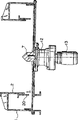
Fig. 1 is vertical front cross sectional view of powder of the present invention and particle feed appliance;
Fig. 2 A is the plan view along the A-A line of Fig. 1;
Fig. 2 B is along the partial plan view of the A-A line of Fig. 1, represents another embodiment;
Fig. 3 is the local inside view along the B-B line of Fig. 1;
Fig. 4 A is the plan view of Fig. 1;
Fig. 4 B is the front elevation of Fig. 4 A;
Fig. 5 A, 5B and 5C are the front elevations of the embodiment of a scraper plate;
Fig. 6 is traditional powder and vertical front cross sectional view of particle feed appliance.
The specific embodiment
A kind of powder and particle feed appliance comprise that a urceolus 1 and spaced and urceolus have inner core up and down 2 and the 2b of common vertical center line c.
The top of urceolus 1 is connected with the outside face of upper inner cylinder 2 is whole by the intermediate (intermediation) of the annular slab 3 on a top, to limit the annular space S on a top.
The bottom of urceolus 1 is connected to the bottom of the inner core 2b of bottom by the intermediate integral body of the annular slab 4 of a bottom, with the annular space (material passage 6) that limits a bottom.
The inner core 2b upper end of bottom is by 5 sealings of a coaxial annular table, and material passage 6 is formed by the following annular space of the bottom of the neighboring of platform 5.
As shown in Figure 1, the inside diameter of upper inner cylinder 2 is bigger than the outer dia of bottom inner core 2b, and the outer dia of platform 5 is identical with the outer dia of upper inner cylinder 2.But the relation about should be noted that between the outer dia of the inner and outer diameter of inner core 2 and 2b and platform 5 is suitably to select according to used material; Be not defined as the situation shown in Fig. 1.
Form an intersection angle recess (intersection angular recess portion) θ between the outer surface of the inner core 2b of the lower surface of the neighboring of platform 5 and bottom.
And, between the upper surface of the outer peripheral face of the lower end 2c of the inner core 2 on top and platform 5, there is a material discharge gap being provided t.
Below the core of the lower surface of platform 5, the intermediate of a drive motor 13 by a reducing gear 12 is set, the output shaft of reducing gear 12 is projected into platform 5 outsides, forms a rotating shaft of holding up 7.
As shown in Figure 1, the base end part of a plurality of (four to six) rotating blade 8 integrally is connected to turning cylinder 7.The front end of rotating blade is connected to a swivel becket 9 by metal fixing 10, and this swivel becket 9 is arranged in the intersection angle recess θ.
Rotating blade 8 is crooked, is converx on rotation direction a.Radius of curvature from the cardinal extremity to the front end reduces gradually.Rotating blade 8 also may be to have a fixing radius of curvature or straight.
As shown in Figure 3, the lower end 2c at the inner core 2 on top equally spaced forms a plurality of downward protrusion 2a.They stop the material of inconsistent shape, compel it by the rotating blade Final 8 and slide in vent gap t, push this material to vent gap t side.
Auxiliary metal piece 14 is set at the inner core 2 by top, among the annular space s on the top that the annular slab 3 on urceolus 1 and top limits, is used to discharge towards the lower end 2c of the inner core 2 on top or the material of vent gap t motion.They stop the waste material of the inconsistent shape of sliding along clearance t, and auxiliary or promote its motion outside the gap.
In Fig. 1, label 15 one of expression are arranged on the material discharge outlet in the material passage 6, the insertion support holes of label 16 expression assistant metal spares 14, the stop part of label 17 expression metal fixings 14, the upper flanges of the inner core 2 on label 18 expression tops, the following end flanges of label 19 expression urceolus 1.In Fig. 6, the traditional adjust the clearance tube of label 20 expressions.
In powder of the present invention and particle feed appliance, as described above, material when inconsistent shape, for example household garbage or industrial waste are put in the inner core on top, and when rotating blade rotated with a direction, the material of inconsistent shape was easy to outwards move along blade or along its curved surfaces.Under the situation that the outer peripheral face radius of curvature near platform reduces, material is easy to extrapolation, by vent gap, falls into material passage.Material can not slide along vent gap.This slip is stoped by downward protrusion or assistant metal spare, and material is easy to drop into following material passage.And material enters into passage by scraping blade guiding, and this scraping blade helps clog-freely the quantitative discharging from material passage auto levelizer outside.
Claims (4)
1. powder and particle feed appliance comprise:
A urceolus, the inner core of the inner core on a top and a bottom, they have common line of centers;
The annular slab on a top, the top and the upper inner cylinder of connection urceolus;
The annular slab of a bottom connects the bottom of urceolus and the bottom of bottom inner core;
The platform of a circle is closed the upper end of bottom inner core, and has a vertical turning cylinder, has a plurality of rotating blades on this axle,
One of them material passage below the neighboring of circular platform formation and
One of them material discharge gap being provided is formed between the lower end of the neighboring of circular platform and upper inner cylinder,
This powder and particle feed appliance also comprise: one is arranged in the material passage, and be connected to by metal fixing rotating blade front end swivel becket and
Scraping blade is arranged in the material passage and is connected to swivel becket,
Swivel becket is arranged in the intersection angle recess that is formed by bottom inner core and circular platform, and
Wherein scraping blade is scraped pawl or a scraper plate forms by the outward-dipping guide rod under the described hoop that descends with from vertically extending one of described guide rod.
2. powder according to claim 1 and particle feed appliance is characterized in that the radius of curvature of rotating blade reduces gradually towards its front end.
3. powder according to claim 1 and particle feed appliance is characterized in that a plurality of downward protrusions are arranged on the lower end of upper inner cylinder.
4. powder according to claim 1 and particle feed appliance, it is characterized in that, one is pointed to the lower end of upper inner cylinder or the material discharge assistant metal spare of vent gap, is set in the upper, annular space that upper inner cylinder, urceolus and upper, annular plate limited.
Applications Claiming Priority (2)
| Application Number | Priority Date | Filing Date | Title |
|---|---|---|---|
| JP2002142746A JP4039885B2 (en) | 2002-05-17 | 2002-05-17 | Powder and particle feeder |
| JP142746/2002 | 2002-05-17 |
Publications (2)
| Publication Number | Publication Date |
|---|---|
| CN1636847A CN1636847A (en) | 2005-07-13 |
| CN100519373C true CN100519373C (en) | 2009-07-29 |
Family
ID=19194586
Family Applications (1)
| Application Number | Title | Priority Date | Filing Date |
|---|---|---|---|
| CNB031220401A Expired - Lifetime CN100519373C (en) | 2002-05-17 | 2003-04-22 | Powder and grain feeder |
Country Status (7)
| Country | Link |
|---|---|
| US (1) | US6860410B2 (en) |
| JP (1) | JP4039885B2 (en) |
| KR (1) | KR100560356B1 (en) |
| CN (1) | CN100519373C (en) |
| DE (1) | DE10321243B4 (en) |
| FR (1) | FR2839707B1 (en) |
| GB (1) | GB2388590B (en) |
Families Citing this family (17)
| Publication number | Priority date | Publication date | Assignee | Title |
|---|---|---|---|---|
| DE10331866B4 (en) * | 2003-07-14 | 2008-11-13 | Minebea Co., Ltd. | Device for controlling a coil arrangement with electrically variable inductance, and switching power supply |
| JP2005343656A (en) * | 2004-06-04 | 2005-12-15 | Bab-Hitachi Industrial Co | Powder and granular material supply device, combustion device, and its operation method |
| US20080237914A1 (en) * | 2005-12-13 | 2008-10-02 | Arnold Lustiger | Methods for making fiber reinforced polypropylene composites using pre-cut fiber |
| JP2007302373A (en) * | 2006-05-09 | 2007-11-22 | Yoshikawa:Kk | Powder and particle feeder |
| US20110000938A2 (en) * | 2007-05-25 | 2011-01-06 | Shionogi & Co., Ltd. | Powder material supply device |
| JP4579308B2 (en) * | 2008-04-25 | 2010-11-10 | 株式会社ヨシカワ | Powder and particle feeder |
| KR101214540B1 (en) * | 2008-07-01 | 2013-01-09 | 츠카사 컴퍼니 리미티드 | Table feeder |
| JP5268598B2 (en) * | 2008-12-01 | 2013-08-21 | 株式会社ヨシカワ | Material transfer device in powder supply machine |
| WO2011038304A1 (en) | 2009-09-28 | 2011-03-31 | Kmc Oil Tools Bv | Drill cuttings methods and systems |
| JP5774362B2 (en) | 2011-04-28 | 2015-09-09 | 株式会社ヨシカワ | Powder and particle feeder with horizontal rotating table |
| JP5856037B2 (en) * | 2012-10-25 | 2016-02-09 | 株式会社ヨシカワ | Metering feeder |
| JP6101617B2 (en) * | 2013-10-23 | 2017-03-22 | 株式会社ヨシカワ | Fixed quantity feeder |
| KR101909333B1 (en) * | 2014-06-27 | 2018-10-17 | 가부시키가이샤 요시카와 | Multi feeder |
| EA031846B1 (en) * | 2014-12-02 | 2019-02-28 | Монтраде С.П.А. | Device and method for discharging material on a moving substrate |
| CN108584442A (en) * | 2018-03-07 | 2018-09-28 | 中国石油大学(华东) | A kind of powder transfer device |
| CN115254339A (en) * | 2022-08-25 | 2022-11-01 | 东北电力大学 | A device for crushing and collecting oil residue |
| CN119565700B (en) * | 2024-12-31 | 2025-07-29 | 广东省创力智能机械设备有限公司 | Cone crusher and method for avoiding stone accumulation pretreatment |
Family Cites Families (11)
| Publication number | Priority date | Publication date | Assignee | Title |
|---|---|---|---|---|
| US2612298A (en) * | 1950-01-25 | 1952-09-30 | United States Steel Corp | Discharge apparatus for coal hoppers |
| US3038643A (en) * | 1958-02-03 | 1962-06-12 | Lely Nv C Van Der | Devices for spreading granular or powdery material |
| US3083471A (en) * | 1960-03-24 | 1963-04-02 | Huntington Chemical Corp | Apparatus for continuous and uniform contacting of fluids and solids |
| DK117188C (en) * | 1967-04-29 | |||
| NL6708370A (en) * | 1967-06-16 | 1968-12-17 | ||
| JPS59138532A (en) * | 1983-01-28 | 1984-08-09 | Taisei Kogyo Kk | Granular powder quantitative supply control method |
| JPH05105239A (en) * | 1991-10-21 | 1993-04-27 | Katsuya Mizui | Supply and discharge apparatus for granular powder |
| DE19501179A1 (en) * | 1995-01-17 | 1996-07-18 | Zeppelin Schuettguttech Gmbh | Device for dosing bulk goods |
| JPH0952629A (en) * | 1995-08-16 | 1997-02-25 | Fuiider Giken:Kk | Ejection device for powder |
| JP3556466B2 (en) * | 1998-04-30 | 2004-08-18 | Jfeスチール株式会社 | Granule cutting device |
| JP4578612B2 (en) * | 2000-03-30 | 2010-11-10 | 株式会社ヨシカワ | Powder and particle feeder |
-
2002
- 2002-05-17 JP JP2002142746A patent/JP4039885B2/en not_active Expired - Lifetime
-
2003
- 2003-03-14 US US10/387,430 patent/US6860410B2/en not_active Expired - Lifetime
- 2003-03-19 GB GB0306321A patent/GB2388590B/en not_active Expired - Fee Related
- 2003-03-25 FR FR0303622A patent/FR2839707B1/en not_active Expired - Fee Related
- 2003-04-09 KR KR1020030022425A patent/KR100560356B1/en not_active Expired - Lifetime
- 2003-04-22 CN CNB031220401A patent/CN100519373C/en not_active Expired - Lifetime
- 2003-05-12 DE DE10321243A patent/DE10321243B4/en not_active Expired - Lifetime
Also Published As
| Publication number | Publication date |
|---|---|
| CN1636847A (en) | 2005-07-13 |
| FR2839707A1 (en) | 2003-11-21 |
| JP4039885B2 (en) | 2008-01-30 |
| US20030213815A1 (en) | 2003-11-20 |
| GB2388590B (en) | 2004-03-31 |
| JP2003335422A (en) | 2003-11-25 |
| US6860410B2 (en) | 2005-03-01 |
| KR100560356B1 (en) | 2006-03-14 |
| DE10321243A1 (en) | 2003-12-04 |
| GB2388590A (en) | 2003-11-19 |
| DE10321243B4 (en) | 2008-03-20 |
| FR2839707B1 (en) | 2005-06-10 |
| KR20030089423A (en) | 2003-11-21 |
| GB0306321D0 (en) | 2003-04-23 |
Similar Documents
| Publication | Publication Date | Title |
|---|---|---|
| CN1636847A (en) | Powder and grain feeder | |
| JP4884718B2 (en) | Powder supply machine in material supply equipment | |
| WO2010140336A1 (en) | Cylindrical sieve and cylindrical shifter | |
| CN1087125A (en) | Be used for the e Foerderanlage that the loose material batching is carried | |
| KR101677769B1 (en) | Apparatus for guiding descent in powder and grain feeder | |
| US4552460A (en) | Bucket-lift slurry storage apparatus and method | |
| US5823123A (en) | Transporting a particulate material to a discharge opening | |
| JP6462508B2 (en) | Multi-feeder and operation method thereof | |
| TW407166B (en) | Shaft furnace | |
| CN208150290U (en) | A kind of bucket elevator of Feed Manufacturing | |
| CN212863248U (en) | A feeding device for rotary kiln | |
| CN113233924B (en) | Rotary rocking shaft type material stirring system | |
| CN210758425U (en) | Turnover type mixer | |
| ES2296647T3 (en) | CRUSHER HEAD. | |
| CN222152240U (en) | Solid waste raw material feeding device | |
| CN2673827Y (en) | Blanking device of storage bin | |
| US5495949A (en) | System for treating solid particles in a medium | |
| CN213193277U (en) | Novel mixer for mixing powder and particles | |
| JP2945328B2 (en) | Waste treatment equipment | |
| CN222808617U (en) | Batching equipment and material conveying system | |
| CN219631060U (en) | Granular fuel stirring equipment | |
| CN217990382U (en) | Feeding conveying device for garbage sorting and classifying device | |
| CN219362589U (en) | Disc feeding device for material conveying | |
| CN224225909U (en) | Transmission structure for endless chain type bucket elevator | |
| CN1057271C (en) | Closure type vertical screw unloading machine for car |
Legal Events
| Date | Code | Title | Description |
|---|---|---|---|
| C06 | Publication | ||
| PB01 | Publication | ||
| C10 | Entry into substantive examination | ||
| SE01 | Entry into force of request for substantive examination | ||
| C14 | Grant of patent or utility model | ||
| GR01 | Patent grant | ||
| CX01 | Expiry of patent term | ||
| CX01 | Expiry of patent term |
Granted publication date: 20090729 |