CN100524083C - Fixing device - Google Patents

Fixing device Download PDF

Info

Publication number
CN100524083C
CN100524083C CNB2004100617741A CN200410061774A CN100524083C CN 100524083 C CN100524083 C CN 100524083C CN B2004100617741 A CNB2004100617741 A CN B2004100617741A CN 200410061774 A CN200410061774 A CN 200410061774A CN 100524083 C CN100524083 C CN 100524083C
Authority
CN
China
Prior art keywords
coil
heating
coils
fixing device
heating element
Prior art date
Legal status (The legal status is an assumption and is not a legal conclusion. Google has not performed a legal analysis and makes no representation as to the accuracy of the status listed.)
Expired - Fee Related
Application number
CNB2004100617741A
Other languages
Chinese (zh)
Other versions
CN1577162A (en
Inventor
木野内聪
高木修
杖田义德
曽根寿浩
Current Assignee (The listed assignees may be inaccurate. Google has not performed a legal analysis and makes no representation or warranty as to the accuracy of the list.)
Toshiba Corp
Toshiba Tec Corp
Original Assignee
Toshiba Corp
Toshiba Tec Corp
Priority date (The priority date is an assumption and is not a legal conclusion. Google has not performed a legal analysis and makes no representation as to the accuracy of the date listed.)
Filing date
Publication date
Priority claimed from JP2003188634A external-priority patent/JP2005024769A/en
Priority claimed from JP2003389751A external-priority patent/JP4402432B2/en
Application filed by Toshiba Corp, Toshiba Tec Corp filed Critical Toshiba Corp
Publication of CN1577162A publication Critical patent/CN1577162A/en
Application granted granted Critical
Publication of CN100524083C publication Critical patent/CN100524083C/en
Anticipated expiration legal-status Critical
Expired - Fee Related legal-status Critical Current

Links

Images
Classifications

    • GPHYSICS
    • G03PHOTOGRAPHY; CINEMATOGRAPHY; ANALOGOUS TECHNIQUES USING WAVES OTHER THAN OPTICAL WAVES; ELECTROGRAPHY; HOLOGRAPHY
    • G03GELECTROGRAPHY; ELECTROPHOTOGRAPHY; MAGNETOGRAPHY
    • G03G15/00Apparatus for electrographic processes using a charge pattern
    • G03G15/20Apparatus for electrographic processes using a charge pattern for fixing, e.g. by using heat
    • G03G15/2003Apparatus for electrographic processes using a charge pattern for fixing, e.g. by using heat using heat
    • G03G15/2014Apparatus for electrographic processes using a charge pattern for fixing, e.g. by using heat using heat using contact heat
    • G03G15/2039Apparatus for electrographic processes using a charge pattern for fixing, e.g. by using heat using heat using contact heat with means for controlling the fixing temperature
    • G03G15/2042Apparatus for electrographic processes using a charge pattern for fixing, e.g. by using heat using heat using contact heat with means for controlling the fixing temperature specially for the axial heat partition
    • GPHYSICS
    • G03PHOTOGRAPHY; CINEMATOGRAPHY; ANALOGOUS TECHNIQUES USING WAVES OTHER THAN OPTICAL WAVES; ELECTROGRAPHY; HOLOGRAPHY
    • G03GELECTROGRAPHY; ELECTROPHOTOGRAPHY; MAGNETOGRAPHY
    • G03G15/00Apparatus for electrographic processes using a charge pattern
    • G03G15/20Apparatus for electrographic processes using a charge pattern for fixing, e.g. by using heat
    • G03G15/2003Apparatus for electrographic processes using a charge pattern for fixing, e.g. by using heat using heat
    • G03G15/2014Apparatus for electrographic processes using a charge pattern for fixing, e.g. by using heat using heat using contact heat
    • G03G15/2053Structural details of heat elements, e.g. structure of roller or belt, eddy current, induction heating

Landscapes

  • Physics & Mathematics (AREA)
  • General Physics & Mathematics (AREA)
  • General Induction Heating (AREA)
  • Fixing For Electrophotography (AREA)

Abstract

A fixing device includes a heating member (2) heated by induction heating, a pressing member (3) applying a pressure to the heating member, and an induction heating mechanism (105, 106) supplying a predetermined magnetic field to the heating member. The induction heating mechanism (105, 106) is provided with a plurality of coils (105a, 161a, and 162 a). By arranging the adjoining coils (105a, 161a) and the adjoining coils (105a, 162a) in a superposed manner, a temperature distribution which is uniform in the length direction of the heating member (2) can be obtained.

Description

定影装置 Fixing device

技术领域 technical field

本发明涉及一种用于将显影剂熔融到一转印材料上的定影装置,该定影装置设置于使用电子照相方式在一转印材料上形成图像的诸如复印机和印刷机的成像装置中。The present invention relates to a fixing device for fusing a developer to a transfer material, which is provided in an image forming device such as a copying machine and a printing machine that forms an image on a transfer material using electrophotography.

背景技术 Background technique

诸如电动复印机的成像装置设有一个通过施加压力来熔融一热熔的显影剂图像到纸上的定影装置。An image forming apparatus such as an electric copier is provided with a fixing device that fuses a hot-fused developer image onto paper by applying pressure.

通常可采用感应加热来作为加热定影装置中加热件的一种方法。感应加热是一种通过向线圈施加一预定的电功率来产生磁场以及通过磁场产生的涡流来产生焦耳热从而在加热件内产生预定的热量的方法。Induction heating is generally used as a method of heating the heating element in the fixing device. Induction heating is a method of generating a predetermined amount of heat in a heating element by applying a predetermined electric power to a coil to generate a magnetic field and Joule heat generated by the eddy current generated by the magnetic field.

例如,KOKAI的日本专利申请公开号No.2001-235962中公开了一种应用感应加热方法的定影装置。在该定影装置中,具有与纸接触的一加热件区域的线圈相对一分开的加热区域而设置,将定影装置按照纸的尺寸分成一预定数量的线圈,并且位于加热件之外。For example, Japanese Patent Application Publication No. 2001-235962 of KOKAI discloses a fixing device applying an induction heating method. In the fixing device, a coil having a heating member area in contact with the paper is disposed opposite to a separate heating region, the fixing device is divided into a predetermined number of coils according to the size of the paper, and is located outside the heating member.

此外,KOKAI的日本专利申请公开号No.2000-206813中公开了一种应用感应加热方法的定影装置,该定影装置设有多个励磁线圈,而且根据向一第一励磁线圈供给的电流量,除了第一励磁线圈之外,控制供给励磁线圈的电流量。In addition, Japanese Patent Application Publication No. 2000-206813 of KOKAI discloses a fixing device applying an induction heating method, the fixing device is provided with a plurality of exciting coils, and according to the amount of current supplied to a first exciting coil, In addition to the first exciting coil, the amount of current supplied to the exciting coil is controlled.

此外,KOKAI的日本专利申请公开号No.7-295414中公开了一种应用感应加热方法的定影装置,该定影装置设有多个位于一加热件之外的励磁线圈,具有加热件与纸接触的区域,按照加热件所加热的纸的尺寸,该定影装置相对一分开的加热区域而设置,而且向多个线圈单独地供给电流。In addition, Japanese Patent Application Laid-Open No. 7-295414 of KOKAI discloses a fixing device using an induction heating method. According to the size of the paper to be heated by the heating member, the fixing device is disposed opposite to a separate heating area, and supplies electric currents individually to the plurality of coils.

在上述三个专利申请公开的应用感应加热方法的定影装置中,具有非常高发热效率的加热件能非常快地加热,而且如果加热是在不转动的状态下进行的,则靠近与励磁线圈相对的部分区域会被局部加热。In the fixing device applying the induction heating method disclosed in the above-mentioned three patent applications, the heating member having a very high heating efficiency can be heated very quickly, and if the heating is performed in a non-rotating state, it is close to the part opposite to the exciting coil. Some areas are locally heated.

此外,KOKAI的日本专利申请公开号No.2002-40839中公开了一种应用感应加热方法通过加热辊来加热具有热熔带的定影装置,而且包括一个探测装置用于探测热熔带沿转动方向的运动。In addition, KOKAI's Japanese Patent Application Laid-Open No. 2002-40839 discloses an application of an induction heating method to heat a fixing device having a hot-melt belt through a heating roller, and includes a detection device for detecting the direction of rotation of the hot-melt belt. exercise.

此外,KOKAI的日本专利申请公开号No.2002-82549中公开了一种定影装置,在该定影装置中,接触由加热件加热的一通过的纸的带子的那部分同与一加压件相配合的一部分分开,其中该加压件向纸供给一预定的压力,而且在带子转动之后该加热件开始感应加热。In addition, Japanese Patent Application Laid-Open No. 2002-82549 of KOKAI discloses a fixing device in which a portion of a belt of a passing paper heated by a heating member is in contact with a pressing member. A part of fitting is separated, wherein the pressing member supplies a predetermined pressure to the paper, and the heating member starts induction heating after the belt is rotated.

在应用感应加热方法的定影装置中,该定影装置使用了多个用于感应加热的线圈,这样,与紧靠线圈中心处产生的磁场相比,与线圈邻接的区域具有较弱的磁场强度。在这种情况下,磁场强度沿加热件的长度方向而变化,而且热量根据加热件的位置不同而改变。In the fixing device applying the induction heating method, the fixing device uses a plurality of coils for induction heating so that the area adjacent to the coils has a weaker magnetic field strength than the magnetic field generated immediately at the center of the coils. In this case, the magnetic field strength varies along the length of the heating element, and the amount of heat varies depending on the location of the heating element.

因此,沿加热件的长度方向的温度分布变得不均匀了,而且向纸上显影剂所供给的热量值变得不稳定了。Therefore, the temperature distribution along the length direction of the heating member becomes non-uniform, and the amount of heat supplied to the developer on the paper becomes unstable.

在近年来注意到的具有薄金属层的加热辊中,特别是多个线圈之间存在的温差成为了一个问题。In heating rollers having a thin metal layer that have been noticed in recent years, the temperature difference that exists particularly between a plurality of coils becomes a problem.

对于用于探测一反常温度的探测装置而言,就需要探测由励磁线圈局部加热的一预定位置处的温度。For detection means for detecting an abnormal temperature, it is necessary to detect the temperature at a predetermined position locally heated by the exciting coil.

然而,在没有设有励磁线圈和用于探测一反常温度的部件的定影装置中,由于加热件被装在里面,所以事实上难以将一个温度探测装置放置在一局部加热的预定位置(例如,在线圈和加热件之间)上。However, in a fixing device not provided with an exciting coil and a member for detecting an abnormal temperature, since the heating member is housed inside, it is actually difficult to place a temperature detecting device at a predetermined position for local heating (for example, between the coil and the heating element).

此外,定影装置使用装在里面的加热件会存在一个问题。由于用于探测反常温度的反常温度探测装置紧靠励磁线圈设置,所以从励磁线圈向加热辊供给的磁场不均匀,而且沿加热件的转动方向的温度也不均匀。In addition, there is a problem in the fixing device using the heating member incorporated therein. Since the abnormal temperature detecting means for detecting the abnormal temperature is located close to the exciting coil, the magnetic field supplied from the exciting coil to the heating roller is not uniform, and the temperature in the direction of rotation of the heating member is also not uniform.

发明内容 Contents of the invention

按照本发明的一方面提供了一种定影装置,包括:According to an aspect of the present invention, there is provided a fixing device, including:

一加热件,该加热件为圆柱形并具有一流过感应加热产生的感生电流的导电金属层;a heating element, the heating element is cylindrical and has an electrically conductive metal layer passing through an induced current generated by induction heating;

一加压件,该加压件向所述的加热件施加一压力;a pressurizing part, which applies a pressure to the heating part;

一第一感应加热机构,该第一感应加热机构包括一第一线圈;a first induction heating mechanism comprising a first coil;

一第二感应加热机构,该第二感应加热机构包括至少一个沿所述加热件的轴向方向与所述第一感应加热机构对准的第二线圈;a second induction heating mechanism comprising at least one second coil aligned with said first induction heating mechanism in the axial direction of said heating element;

其中,所述第一线圈和第二线圈具有至少一个端部,该端部朝向所述加热件的相对侧倾斜,其特征在于,第一和第二线圈具有与加热件的外圆周对应的特定曲率。Wherein, the first coil and the second coil have at least one end portion, which is inclined towards the opposite side of the heating element, and it is characterized in that the first and second coils have a specific diameter corresponding to the outer circumference of the heating element. curvature.

本发明的另一方面提供了一种定影装置,该定影装置包括:Another aspect of the present invention provides a fixing device, the fixing device includes:

一加热件,该加热件为圆柱形并具有一流过感应加热产生的感生电流的导电金属层;a heating element, the heating element is cylindrical and has an electrically conductive metal layer passing through an induced current generated by induction heating;

一加压件,该加压件向所述的加热件施加一压力;a pressurizing part, which applies a pressure to the heating part;

一第一感应加热机构,该第一感应加热机构包括一第一线圈;a first induction heating mechanism comprising a first coil;

一第二感应加热机构,该第二感应加热机构包括至少一个沿所述加热件的轴向方向与所述第一感应加热机构对准的第二线圈;a second induction heating mechanism comprising at least one second coil aligned with said first induction heating mechanism in the axial direction of said heating element;

其中,所述第一线圈包括平行的金属线部分和第一直线部分,所述金属线部分在平行于加热件的轴向方向上延伸,所述第一直线部分将一个平行的金属线部分与另一个平行的金属线部分连接,所述第一直线部分在邻接第二线圈的端部处沿与加热件的轴向方向相交某一角度的特定方向延伸;Wherein, the first coil includes a parallel metal wire portion and a first straight line portion, the metal wire portion extends parallel to the axial direction of the heating element, and the first straight line portion connects a parallel metal wire partly connected to another parallel wire part, said first straight part extending in a certain direction intersecting an axial direction of the heating element at an angle at an end adjacent to the second coil;

所述第二线圈包括在邻接第一线圈的端部处沿所述特定方向延伸的直线部分;以及The second coil includes a straight portion extending in the specific direction at an end adjacent to the first coil; and

所述第一线圈的第一直线部分和所述第二线圈的直线部分彼此平行设置。The first straight portion of the first coil and the straight portion of the second coil are arranged parallel to each other.

本发明的另一方面提供了一种定影装置,包括:Another aspect of the present invention provides a fixing device, including:

一加热件,该加热件为圆柱形并具有一流过感应加热产生的感生电流的导电金属层;a heating element, the heating element is cylindrical and has an electrically conductive metal layer passing through an induced current generated by induction heating;

一加压件,该加压件向所述的加热件施加一压力;a pressurizing part, which applies a pressure to the heating part;

一第一感应加热机构,该第一感应加热机构包括一第一线圈;a first induction heating mechanism comprising a first coil;

一第二感应加热机构,该第二感应加热机构包括至少一个沿所述加热件的轴向方向与所述第一感应加热机构对准的第二线圈;a second induction heating mechanism comprising at least one second coil aligned with said first induction heating mechanism in the axial direction of said heating element;

其中所述第二线圈具有一位于中心部分和加热件之间的第一间隔,和一位于邻接该第一线圈的端部和加热件之间的第二间隔,而且该第一间隔比第二间隔窄;Wherein the second coil has a first space between the central portion and the heating element, and a second space between the end adjacent to the first coil and the heating element, and the first space is larger than the second space. Narrow spacing;

第一线圈在中心部分和端部均距加热件所述第一间隔;以及the first coil is spaced apart from the heating element by the first spacing at both the central portion and the ends; and

第一线圈的端部和第二线圈的与该第一线圈的端部邻接的端部沿垂直于加热件的轴向的方向彼此叠置但不接触。An end portion of the first coil and an end portion of the second coil adjacent to the end portion of the first coil overlap each other in a direction perpendicular to the axial direction of the heating member without contacting.

本发明的另一方面提供了一种定影装置,包括:Another aspect of the present invention provides a fixing device, including:

一加热件,该加热件为圆柱形并具有一流过感应加热产生的感生电流的导电金属层;a heating element, the heating element is cylindrical and has an electrically conductive metal layer passing through an induced current generated by induction heating;

一加压件,该加压件向所述的加热件施加一压力;a pressurizing part, which applies a pressure to the heating part;

一第一感应加热机构,该第一感应加热机构包括一第一线圈;a first induction heating mechanism comprising a first coil;

一第二感应加热机构,该第二感应加热机构包括至少一个沿所述加热件的轴向方向与所述第一感应加热机构对准的第二线圈;a second induction heating mechanism comprising at least one second coil aligned with said first induction heating mechanism in the axial direction of said heating element;

其中第一和第二线圈在线圈的中心部分和加热件之间的间隔比在线圈的端部和加热件之间的间隔宽。Wherein the interval between the central portion of the coil and the heating member of the first and second coils is wider than the interval between the ends of the coil and the heating member.

本发明的另一方面提供了一种定影装置,包括:Another aspect of the present invention provides a fixing device, including:

一加热件,该加热件为圆柱形并设有一流过感应加热产生的感生电流的导电金属层;A heating element, the heating element is cylindrical and is provided with a conductive metal layer passing through an induced current generated by induction heating;

一加压件,该加压件向所述加热件施加一压力;a pressurizing member that applies a pressure to the heating member;

一第一感应加热机构,该第一感应加热机构包括一第一线圈,所述第一线圈给所述加热件提供磁场,并将所述加热件的预定区域加热;A first induction heating mechanism, the first induction heating mechanism includes a first coil, the first coil provides a magnetic field to the heating element, and heats a predetermined area of the heating element;

一第二感应加热机构,该第二感应加热机构包括至少一个以与该第一感应加热机构的第一线圈不同的角度和相位而设置的第二线圈,所述第二线圈被构造成给所述加热件提供磁场,并将加热件的预定区域加热;a second induction heating mechanism comprising at least one second coil arranged at a different angle and phase from the first coil of the first induction heating mechanism, the second coil being configured to give the The heating element provides a magnetic field and heats a predetermined area of the heating element;

其中,所述第一线圈具有一端部且第二线圈具有一在加热件的圆周方向与第一线圈的端部叠置的端部。Wherein, the first coil has an end and the second coil has an end overlapping with the end of the first coil in the circumferential direction of the heating element.

本发明的其它目的和优点在随后结合说明书的描述或者通过本发明的实践将变得更清楚。本发明的目的和优点通过下面结合实施例的描述可以来获得。Other purposes and advantages of the present invention will become clearer later in combination with the description of the specification or through the practice of the present invention. The objects and advantages of the present invention can be obtained by the following description with reference to the embodiments.

附图说明 Description of drawings

作为说明书一部分的附图示出了本发明的优选实施例,结合下面对实施例的描述和以上所作的一般说明都可用于解释本发明的原理。The accompanying drawings, which constitute a part of this specification, illustrate preferred embodiments of the invention and, together with the description of the embodiments below and the foregoing general description, serve to explain the principles of the invention.

图1是本发明一实施例中定影装置的示意图;FIG. 1 is a schematic diagram of a fixing device in an embodiment of the present invention;

图2是用于图1中定影装置的感应加热控制电路的结构方框图;Fig. 2 is a structural block diagram of an induction heating control circuit used in the fixing device in Fig. 1;

图3是用于解释控制图1中定影装置的方法的一个实施例的流程图;FIG. 3 is a flowchart for explaining one embodiment of a method of controlling the fixing device in FIG. 1;

图4A、4B和4C是解释图2中感应加热机构的另一个实施例的示意图;4A, 4B and 4C are schematic diagrams illustrating another embodiment of the induction heating mechanism in FIG. 2;

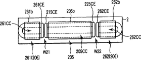
图5A和5B是解释紧邻图4A、4B和4C中感应加热机构而设置的反常温度探测机构的布置实例的示意图;5A and 5B are schematic diagrams for explaining an arrangement example of an abnormal temperature detecting mechanism provided next to the induction heating mechanism in FIGS. 4A, 4B and 4C;

图6A、6B、6C和6D是解释图2中感应加热机构的其它实施例的示意图;6A, 6B, 6C and 6D are schematic diagrams illustrating other embodiments of the induction heating mechanism in FIG. 2;

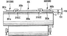
图7A和7B是解释图2中感应加热机构的其它实施例的示意图;7A and 7B are schematic diagrams illustrating other embodiments of the induction heating mechanism in FIG. 2;

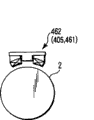
图8A、8B和8C是解释图2中感应加热机构的其它实施例的示意图;8A, 8B and 8C are schematic diagrams illustrating other embodiments of the induction heating mechanism in FIG. 2;

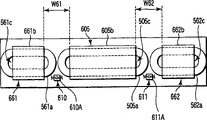
图9A和图9B是解释图1所示的定影装置中感应加热机构和反常温度探测机构之间关系的一个实施例的示意图;9A and 9B are schematic diagrams explaining one embodiment of the relationship between the induction heating mechanism and the abnormal temperature detecting mechanism in the fixing device shown in FIG. 1;

图10是解释图9A和图9B中反常温度机构的一个实施例的示意图;Figure 10 is a schematic diagram explaining one embodiment of the abnormal temperature mechanism in Figures 9A and 9B;

图11是解释图1所示的定影装置中感应加热机构和反常温度探测机构之间关系的另一个实施例的示意图;11 is a schematic diagram for explaining another embodiment of the relationship between the induction heating mechanism and the abnormal temperature detecting mechanism in the fixing device shown in FIG. 1;

图12A、12B和12C是解释图1所示的定影装置中感应加热机构和反常温度探测机构之间关系的再一个实施例的示意图;12A, 12B and 12C are diagrams for explaining still another embodiment of the relationship between the induction heating mechanism and the abnormal temperature detecting mechanism in the fixing device shown in FIG. 1;

图13A、13B和13C是解释图2所示的感应加热机构另一个实施例的示意图;13A, 13B and 13C are schematic diagrams illustrating another embodiment of the induction heating mechanism shown in FIG. 2;

图14A和14B是解释本发明的定影装置中纸输送形式的透视图;14A and 14B are perspective views explaining the form of paper conveyance in the fixing device of the present invention;

图15A、15B和15C是解释图2所示的感应加热机构其它实施例的示意图;15A, 15B and 15C are schematic diagrams illustrating other embodiments of the induction heating mechanism shown in FIG. 2;

图16是解释图15A、15B和15C中所示的感应加热控制电路的结构的方框图;Fig. 16 is a block diagram explaining the structure of the induction heating control circuit shown in Figs. 15A, 15B and 15C;

图17A、17B和17C是解释图2所示的感应加热机构其它实施例的示意图;17A, 17B and 17C are schematic diagrams illustrating other embodiments of the induction heating mechanism shown in FIG. 2;

图18是解释图1中定影装置的另一个感应加热控制电路的结构的方框图;18 is a block diagram for explaining the structure of another induction heating control circuit of the fixing device in FIG. 1;

图19A、19B、19C和19D是解释在图18中所示逆变电路的等效电路中电流流动的电路图;以及19A, 19B, 19C and 19D are circuit diagrams explaining the flow of current in the equivalent circuit of the inverter circuit shown in FIG. 18; and

图20A和20B示出流过在图18中所示逆变电路的等效电路中电流和时间之间关系的示意图。20A and 20B are diagrams showing the relationship between current and time flowing in an equivalent circuit of the inverter circuit shown in FIG. 18 .

具体实施方式 Detailed ways

下面,结合附图对本发明的实施例进行详细说明。Hereinafter, embodiments of the present invention will be described in detail with reference to the accompanying drawings.

图1示出了本发明定影装置的一个实施例。Fig. 1 shows an embodiment of the fixing device of the present invention.

如图1所示,定影装置设有加热件(加热辊)2和向该加热辊2施加一预定压力的加压件(加压辊)3,其中,该加热件2接触粘有色粉T的纸P或转印材料的表面,并且加热色粉T和纸P。As shown in FIG. 1, the fixing device is provided with a heating member (heating roller) 2 and a pressing member (pressing roller) 3 that applies a predetermined pressure to the heating roller 2, wherein the heating member 2 is in contact with the toner T. The surface of the paper P or transfer material, and the toner T and paper P are heated.

加热辊2包括在一预定压力下不会变形的芯金属2a或者金属轴(具有高硬度),在芯金属2a周围依次设有海绵橡胶层(海绵状物)2b、导电金属层2c、固体橡胶层2d和模制润滑层2e。可优选的是,海绵橡胶层(海绵状物)2b的厚度为5mm,导电金属层2c的厚度为40μm,固体橡胶层2d的厚度为200μm,以及模制释放层2e的厚度为40μm。加热辊2优选具有40mm的直径。导电金属层2c是由导电材料(例如镍、不锈钢、铝、铜、不锈钢和铝的合成材料等)制成的。The heat roller 2 includes a core metal 2a or a metal shaft (with high hardness) that is not deformed under a predetermined pressure, and a sponge rubber layer (sponge) 2b, a conductive metal layer 2c, a solid rubber layer are sequentially provided around the core metal 2a. Layer 2d and molded lubricant layer 2e. It is preferable that the thickness of the sponge rubber layer (sponge) 2b is 5 mm, the thickness of the conductive metal layer 2c is 40 μm, the thickness of the solid rubber layer 2d is 200 μm, and the thickness of the mold release layer 2e is 40 μm. The heat roller 2 preferably has a diameter of 40 mm. The conductive metal layer 2c is made of a conductive material such as nickel, stainless steel, aluminum, copper, a composite material of stainless steel and aluminum, or the like.

可优选的是,加压辊3包括在一预定压力下不会变形的芯金属3a或者金属轴(具有高硬度),围绕该芯金属3a设置的硅橡胶3b和氟橡胶3c,而且该加压辊3具有40mm的直径。It is preferable that the pressing roller 3 includes a core metal 3a or a metal shaft (having high hardness) which is not deformed under a predetermined pressure, silicon rubber 3b and fluororubber 3c provided around the core metal 3a, and the pressing Roller 3 has a diameter of 40 mm.

加压辊3通过接收来自于加压机构4的压力而向加热辊2施加一预定的压力。加热辊2以和加压辊3之间具有某一挤压宽被来接触加压辊3,加热辊2在一驱动电动机(没有示出)的作用下沿箭头方向(顺时针)旋转。当加热辊2旋转时,加压辊3沿箭头方向(逆时针)旋转。The pressure roller 3 applies a predetermined pressure to the heat roller 2 by receiving pressure from the pressure mechanism 4 . The heating roller 2 is brought into contact with the pressing roller 3 with a certain nip width therebetween, and the heating roller 2 is rotated in the arrow direction (clockwise) by a driving motor (not shown). When the heat roller 2 rotates, the pressure roller 3 rotates in the arrow direction (counterclockwise).

线圈主体(感应加热机构)5/6向加热辊2的导电金属层2c提供一预定的磁场,将该线圈主体设置在加热辊2之外,并且与该辊2的外圆周表面相距一预定的间隔。The coil main body (induction heating mechanism) 5/6 provides a predetermined magnetic field to the conductive metal layer 2c of the heating roller 2, and the coil main body is arranged outside the heating roller 2 and is separated from the outer peripheral surface of the roller 2 by a predetermined distance. interval.

线圈主体5/6在接收一预定的电流或电压时就产生一预定的磁场。通过来自线圈主体5/6的磁场,加热辊2的导电金属层2c内产生涡流,继而产生焦耳热。色粉T通过来自于加热辊2的热量而热熔,并且当粘附着色粉T的纸P通过位于加热辊2和加压辊3之间的接触部分(挤压部分)并接受加压辊3的一预定压力作用时,该色粉被固定到纸P上。The coil body 5/6 generates a predetermined magnetic field when receiving a predetermined current or voltage. By the magnetic field from the coil main body 5/6, an eddy current is generated in the conductive metal layer 2c of the heating roller 2, and then Joule heat is generated. The toner T is thermally fused by the heat from the heat roller 2, and when the paper P to which the toner T is adhered passes through the contact portion (press portion) between the heat roller 2 and the pressure roller 3 and receives the pressure roller The toner is fixed to the paper P when a predetermined pressure of 3 is applied.

在加热辊2的圆周上,从位于加热辊2和加压辊3之间的接触部分(挤压部分)沿旋转方向依次设有用于将纸P从加热辊2分离下来的分离刀片7和用于施加模制润滑剂(例如硅油)以避免加热辊2的圆周偏置的模制润滑剂施加装置8。在加热辊2的长度方向的一预定位置上,设有用于探测围绕加热辊2圆周方向的温度的热敏电阻9a和9b。在本实施例中,只使用了两个热敏电阻9a和9b,但是还可以使用三个或更多个。On the circumference of the heating roller 2, a separation blade 7 for separating the paper P from the heating roller 2 and a separation blade 7 for separating the paper P from the heating roller 2 are provided sequentially in the direction of rotation from the contact portion (pressing portion) between the heating roller 2 and the pressure roller 3. A molding lubricant applicator 8 for applying a molding lubricant (such as silicone oil) to avoid circumferential offset of the heating roller 2 . At a predetermined position in the longitudinal direction of the heat roller 2, thermistors 9a and 9b for detecting the temperature around the heat roller 2 in the circumferential direction are provided. In this embodiment, only two thermistors 9a and 9b are used, but three or more may be used.

在靠近线圈主体5和6处,设有一个反常温度探测机构(恒温器)10,该机构在加热辊2的温度达到一反常值时可切断向线圈5和6供给的电流或者电压。Near the coil main bodies 5 and 6, there is provided an abnormal temperature detecting mechanism (thermostat) 10 which cuts off the current or voltage supplied to the coils 5 and 6 when the temperature of the heating roller 2 reaches an abnormal value.

图2示出了用于图1中定影装置的感应加热控制电路的结构。FIG. 2 shows the structure of an induction heating control circuit used in the fixing device of FIG. 1. Referring to FIG.

感应加热控制电路具有线圈电流控制电路200、整流电路25、商用AC电源26、输入功率监控器27、CPU28和热敏电阻31和32。商用AC电源26是一种能提供电能的电源,以便操作本发明的定影装置,而且该电源26也向设有定影装置的复印机等供给一部分的电能。The induction heating control circuit has a coil current control circuit 200 , a rectification circuit 25 , a commercial AC power supply 26 , an input power monitor 27 , a CPU 28 , and thermistors 31 and 32 . The commercial AC power source 26 is a power source capable of supplying power to operate the fixing device of the present invention, and this power source 26 also supplies a part of power to a copier or the like provided with the fixing device.

线圈电流控制电路200包括线圈主体5、线圈主体61和线圈主体62,其中,线圈主体5位于与加热辊2的中心区域(即纸P频繁通过的区域)相对的位置上;线圈主体61位于加热辊2的一端沿加热辊2的轴向方向处于与线圈主体5对准状态时的相对位置上;线圈主体62与线圈主体5对准并面对与线圈主体62相对的加热辊2的另一端。线圈主体5包括励磁线圈5a,线圈主体61包括励磁线圈61a,而线圈主体62包括励磁线圈62a。如图2所示,励磁线圈61a和62a串联并电连接一个线圈,而且在说明线圈主体61和62时其被解释为线圈主体6而进行说明。The coil current control circuit 200 includes a coil main body 5, a coil main body 61 and a coil main body 62, wherein the coil main body 5 is located at a position opposite to the central area of the heating roller 2 (ie, the area where the paper P frequently passes); the coil main body 61 is located at the heating roller 2. One end of the roller 2 is in a position relative to the coil main body 5 in the axial direction of the heating roller 2; the coil main body 62 is aligned with the coil main body 5 and faces the other end of the heating roller 2 opposite to the coil main body 62 . The coil main body 5 includes an exciting coil 5a, the coil main body 61 includes an exciting coil 61a, and the coil main body 62 includes an exciting coil 62a. As shown in FIG. 2 , the exciting coils 61 a and 62 a are electrically connected in series as one coil, and the coil main bodies 61 and 62 are described as the coil main body 6 .

第一谐振电路包括励磁线圈5a和与其并联的谐振电容器21。第一逆变电路包括第一谐振电路和与其串联的开关元件23。The first resonance circuit includes an exciting coil 5a and a resonance capacitor 21 connected in parallel thereto. The first inverter circuit includes a first resonance circuit and a switching element 23 connected in series thereto.

第二谐振电路包括励磁线圈6a和与其并联的谐振电容器22。励磁线圈6a是串联到励磁线圈61a和励磁线圈62a的一个线圈。第二逆变电路包括第二谐振电路和与其串联的开关元件24。对于开关元件23和24而言,可以使用能承受高电压和大电流的IGB或MOS-FET。The second resonance circuit includes an exciting coil 6a and a resonance capacitor 22 connected in parallel thereto. The exciting coil 6a is one coil connected in series to the exciting coil 61a and the exciting coil 62a. The second inverter circuit includes a second resonance circuit and a switching element 24 connected in series thereto. For the switching elements 23 and 24, IGB or MOS-FETs capable of withstanding high voltage and large current can be used.

商用AC电源26提供的电流经整流电路25整流后向第一逆变电路和第二逆变电路供给DC电流。将用于监控输入功率PI或者从商用AC电源26提供的电流和电压之乘积的输入功率监控器27和恒温器10连接在整流电路25和商用AC电源26之间。The current provided by the commercial AC power supply 26 is rectified by the rectification circuit 25 and then supplies DC current to the first inverter circuit and the second inverter circuit. An input power monitor 27 for monitoring input power PI or the product of current and voltage supplied from a commercial AC power source 26 and a thermostat 10 are connected between the rectification circuit 25 and the commercial AC power source 26 .

输入功率监控器27包括一个与商用AC电源26相连的变压器27a和一个用于探测来自变压器27a的输入功率PI的输入功率探测电路27b。输入功率探测电路27b与CPU28相连,这样,将通过变压器27a探测到的输入功率PI的信息反馈给CPU28。The input power monitor 27 includes a transformer 27a connected to the commercial AC power source 26 and an input power detection circuit 27b for detecting the input power PI from the transformer 27a. The input power detection circuit 27b is connected to the CPU 28, so that the information of the input power PI detected by the transformer 27a is fed back to the CPU 28.

将CPU28连接到存储器28a、计时器28b和IGBT驱动电路29和30上。将IGBT驱动电路29连接到开关元件23的控制端上。将IGBT驱动电路30连接到开关元件24的控制端上。当CPU28操作IGBT驱动电路29和30时,高频电流将流过励磁线圈5a、61a和62a,从而产生一预定的磁场。当将该预定的磁场提供给加热辊2时,在加热辊2内产生涡流,而且励磁线圈5a和励磁线圈61a/62a分别在加热辊2的预定区域2A(中心区域)和2B(端部区域)中产生热量。用于探测加热辊2的表面温度的热敏电阻31和32分别靠近加热辊2的预定区域2A和2B而设置。The CPU 28 is connected to a memory 28a, a timer 28b, and IGBT drive circuits 29 and 30. The IGBT drive circuit 29 is connected to the control terminal of the switching element 23 . The IGBT drive circuit 30 is connected to the control terminal of the switching element 24 . When the CPU 28 operates the IGBT drive circuits 29 and 30, high frequency current flows through the exciting coils 5a, 61a and 62a, thereby generating a predetermined magnetic field. When this predetermined magnetic field is supplied to the heating roller 2, eddy currents are generated in the heating roller 2, and the exciting coil 5a and the exciting coils 61a/62a are formed in predetermined regions 2A (center region) and 2B (end regions) of the heating roller 2, respectively. ) generates heat. Thermistors 31 and 32 for detecting the surface temperature of the heating roller 2 are provided near predetermined areas 2A and 2B of the heating roller 2, respectively.

热敏电阻31和32将探测到的加热辊2的表面温度作为温度探测信号(电压值)输出到CPU28。根据该温度探测信号,CPU28能选择IGBT驱动电路29和30。例如,当热敏电阻31的温度比热敏电阻32的温度低一预定的度数时,CPU28就驱动与励磁线圈5a相连的IGBT驱动电路29以便加热加热辊的中心区域2A。相反,当热敏电阻32的温度比热敏电阻31的温度低一预定的度数时,CPU28就驱动与励磁线圈61a和62a相连的IGBT驱动电路30以便加热加热辊的端部区域2B。这样,加热辊的中心区域2A和端部区域2B能交替被加热。The thermistors 31 and 32 output the detected surface temperature of the heating roller 2 to the CPU 28 as a temperature detection signal (voltage value). Based on this temperature detection signal, CPU 28 can select IGBT drive circuits 29 and 30 . For example, when the temperature of the thermistor 31 is lower than the temperature of the thermistor 32 by a predetermined degree, the CPU 28 drives the IGBT drive circuit 29 connected to the exciting coil 5a to heat the central region 2A of the heating roller. Conversely, when the temperature of the thermistor 32 is lower than the temperature of the thermistor 31 by a predetermined degree, the CPU 28 drives the IGBT drive circuit 30 connected to the exciting coils 61a and 62a to heat the end region 2B of the heating roller. In this way, the central region 2A and the end regions 2B of the heating roller can be heated alternately.

在本发明的定影装置中应用的感应加热控制电路并不限于上述结构。还可以使用能独立地改变向开关元件23和24供给驱动电压的频率的半桥式电路以及一guasi-E级电路。对于连接到第一和第二逆变电路的驱动电路而言,可以使用PWM(脉冲宽度调制)电路。The induction heating control circuit used in the fixing device of the present invention is not limited to the above structure. It is also possible to use a half-bridge circuit capable of independently changing the frequency of driving voltage supplied to the switching elements 23 and 24, and a guasi-E class circuit. For the drive circuit connected to the first and second inverter circuits, a PWM (Pulse Width Modulation) circuit may be used.

下面,结合附图2的电路说明操作定影装置的方法的一个实施例。Next, an embodiment of the method for operating the fixing device will be described with reference to the circuit shown in FIG. 2 .

首先,说明交替地加热加热辊2的中心区域2A和端部区域2B的方法。First, a method of alternately heating the central region 2A and the end regions 2B of the heating roller 2 will be described.

CPU28指示IGBT驱动电路29和30以一预定的比率(时间比)交替地向励磁线圈5a和6a供给电流或电压(下文中称作线圈输出功率或这种电流和电压的乘积)。假设IGBT驱动电路29向励磁线圈5a输出的功率的时间为2而IGBT驱动电路30向励磁线圈6a输出的功率的时间为1,并且设定加热辊2在加热纸P通过频繁的中心部分具有更大的时间比。IGBT驱动电路29和30向开关元件23和24的控制端交替地以CPU28指示的时限和频率供给作为ON/OFF信号的驱动电压。The CPU 28 instructs the IGBT drive circuits 29 and 30 to alternately supply current or voltage to the exciting coils 5a and 6a at a predetermined ratio (time ratio) (hereinafter referred to as coil output power or the product of such current and voltage). Assuming that the time of the IGBT drive circuit 29 outputting power to the excitation coil 5a is 2 and the time of the IGBT drive circuit 30 outputting power to the excitation coil 6a is 1, and setting the heating roller 2 to have a more central portion where the heating paper P passes frequently. Big time ratio. The IGBT drive circuits 29 and 30 alternately supply drive voltages as ON/OFF signals to the control terminals of the switching elements 23 and 24 at the timing and frequency instructed by the CPU 28 .

例如,通过向开关元件23供给驱动电压而使其接通,并且因没有向开关元件24供给驱动电压而使其断开。For example, the switching element 23 is turned on by supplying a driving voltage to it, and it is turned off by not supplying a driving voltage to the switching element 24 .

当IGBT驱动电路29使开关元件23接通时,整流电路25向励磁线圈5a提供与驱动电压的频率(在本实施例中包括20-50kHz的高频电流)相应的预定功率。励磁线圈5a产生与输入功率相应的磁场。当这种磁场产生时,涡流在加热辊2靠近励磁线圈5a的预定区域2A中流动,而且该加热辊2由于焦耳热而被加热。类似地,当驱动电路30使开关元件24接通时,加热辊2的预定区域2B被加热了。When the IGBT driving circuit 29 turns on the switching element 23, the rectifying circuit 25 supplies predetermined power corresponding to the frequency of the driving voltage (including high-frequency current of 20-50 kHz in this embodiment) to the exciting coil 5a. The exciting coil 5a generates a magnetic field corresponding to the input power. When such a magnetic field is generated, an eddy current flows in a predetermined region 2A of the heating roller 2 close to the exciting coil 5a, and the heating roller 2 is heated due to Joule heat. Similarly, when the drive circuit 30 turns on the switching element 24, the predetermined region 2B of the heating roller 2 is heated.

由于加热辊2在加热时通过驱动电动机(没有示出)而旋转起来,所以在加热辊2靠近励磁线圈5a和6a的预定区域2A和2B的圆周方向上,加热辊2的表面上的温度分布均匀了。Since the heating roller 2 is rotated by driving the motor (not shown) when heating, the temperature distribution on the surface of the heating roller 2 in the circumferential direction of the predetermined regions 2A and 2B near the exciting coils 5a and 6a of the heating roller 2 even out.

此外,根据通过加热辊2和加压辊3之间的纸P的尺寸,通过有选择地改变向位于加热辊2的中心区域的励磁线圈5a和位于加热辊2的端部区域的励磁线圈6a供给的功率的时间能使加热辊2的表面均匀地被加热。In addition, according to the size of the paper P passing between the heating roller 2 and the pressing roller 3, by selectively changing the direction to the exciting coil 5 a located in the center area of the heating roller 2 and the exciting coil 6 a located in the end area of the heating roller 2 The timing of the power supply enables the surface of the heating roller 2 to be heated uniformly.

具体地讲,当A4或A3尺寸纸的长边平行于加热辊2的长度方向而经过时,并且当全尺寸的纸(其一侧边沿加热辊2的长度方向具有与纸经过区域相同的长度)经过时,功率是以相对位于加热辊2的中心区域的励磁线圈5b和位于加热辊2的端部区域的励磁线圈6b基本上相同的比率来提供。Specifically, when the long side of A4 or A3 size paper passes parallel to the lengthwise direction of the heat roller 2, and when full-sized paper (one side of which has the same length as the paper passing area along the lengthwise direction of the heat roller 2 ) passes, power is supplied at substantially the same ratio with respect to the exciting coil 5 b located in the central region of the heating roller 2 and the exciting coil 6 b located in the end region of the heating roller 2 .

相反,当经过诸如明信片这类小尺寸纸时,或者当A4尺寸纸的短边沿平行于加热辊2的长度方向而送入时,设定向位于中心区域的励磁线圈5a供给的功率大于向位于端部区域的励磁线圈6a供给的功率的比率。Conversely, when passing small-sized paper such as postcards, or when the short edge of A4-sized paper is fed in parallel to the lengthwise direction of the heat roller 2, set the power supplied to the exciting coil 5a located in the central area to be larger than that supplied to the coil located in the central area. The ratio of the power supplied by the field coil 6a in the end region.

此外,当向励磁线圈5a和6a供给的线圈输出功率(向线圈5a和6a供给的电流和电压的乘积)的最大值根据操作方式而改变时,通过将向开关元件23和24供给的驱动电压的频率控制在20-50kHz的范围内而使线圈输出功率能在700W-1500W的范围内变化。In addition, when the maximum value of the coil output power supplied to the exciting coils 5a and 6a (the product of the current supplied to the coils 5a and 6a and the voltage) is changed depending on the operation mode, the driving voltage supplied to the switching elements 23 and 24 The frequency is controlled in the range of 20-50kHz so that the output power of the coil can be changed in the range of 700W-1500W.

下面,结合附图2的电路说明操作定影装置的另一个实施例。Next, another embodiment for operating the fixing device will be described with reference to the circuit of FIG. 2 .

图3示出通过使用图2的定影装置的操作方法的另一个实施例的流程图。FIG. 3 illustrates a flow chart of another embodiment of an operating method by using the fixing device of FIG. 2 .

在向如图2所示的励磁线圈5a和6a供给功率的方法中,当将功率供给到一个励磁线圈5a时,就不会向另一个励磁线圈6a供给功率了。现在说明同时向励磁线圈5a和6a供给功率的控制方法。In the method of supplying power to the exciting coils 5a and 6a shown in FIG. 2, when power is supplied to one exciting coil 5a, power is not supplied to the other exciting coil 6a. A control method for simultaneously supplying power to the exciting coils 5a and 6a will now be described.

如图3的实施例所示,在CPU28的控制下,从商用电源26向励磁线圈5a供给的中心线圈输出功率P(5a)与向励磁线圈6a供给的端部线圈输出功率P(6a)之和,或总的线圈输出功率P(5a+6a)假设为900W。即,一预定的总的线圈输出功率P(5a+6a)以一预定比率分配给励磁线圈5a和6a,而且同时供给。此时,加热辊2的预定区域2A的温度TC(靠近位于加热辊2的中心的励磁线圈5a)通过热敏电阻31来探测,而且在经过步骤(S1)时与设置在CPU28内的待机温度TS(例如160℃)相比较,色粉在该待机温度时能被固定到纸上。As shown in the embodiment of FIG. 3, under the control of the CPU 28, the difference between the central coil output power P(5a) supplied from the commercial power supply 26 to the exciting coil 5a and the end coil output power P(6a) supplied to the exciting coil 6a is And, or the total coil output power P(5a+6a) is assumed to be 900W. That is, a predetermined total coil output power P(5a+6a) is distributed to the exciting coils 5a and 6a at a predetermined ratio and supplied simultaneously. At this time, the temperature TC of the predetermined area 2A of the heat roller 2 (near the exciting coil 5a located at the center of the heat roller 2) is detected by the thermistor 31, and is compared with the standby temperature set in the CPU 28 when passing through the step (S1). TS (for example, 160° C.), at which the toner can be fixed to the paper.

当热敏电阻31探测到的温度TC低于待机温度TS(S1-YES)时,热敏电阻31探测到的温度TC还与由热敏电阻32探测到的加热辊的预定位置2B(靠近位于加热辊2的端部区域的励磁线圈6a)的温度TE相比较(S2)。当热敏电阻31探测到的温度TC高于待机温度TS(S1-NO)时,步骤S1结束。When the temperature TC detected by the thermistor 31 is lower than the standby temperature TS (S1-YES), the temperature TC detected by the thermistor 31 is also consistent with the predetermined position 2B of the heating roller detected by the thermistor 32 (closer to The temperatures TE of the field coil 6a) in the end region of the heating roller 2 are compared (S2). When the temperature TC detected by the thermistor 31 is higher than the standby temperature TS(S1-NO), step S1 ends.

当端部区域的温度TE高于加热辊2的中心区域的温度TC(S2-NO)时,需要判断温度TC与TE之间的差是否小于第一预定的温度(例如5℃)。当温度TC与TE之间的差小于5℃时,向励磁线圈5a和6a供给相同值(相同比率)的功率(S3-YES)。即,总的线圈输出功率900W以5:5的配给量来分配,分别将450W的功率供给到励磁线圈(中心线圈)5a和励磁线圈(端部线圈)6a。When the temperature TE of the end region is higher than the temperature TC (S2-NO) of the central region of the heat roller 2, it is necessary to judge whether the difference between the temperature TC and TE is smaller than a first predetermined temperature (for example, 5° C.). When the difference between the temperatures TC and TE is less than 5°C, power of the same value (same ratio) is supplied to the exciting coils 5a and 6a (S3-YES). That is, the total coil output power of 900W is distributed at a ratio of 5:5, and 450W of power is supplied to the exciting coil (center coil) 5a and the exciting coil (end coil) 6a respectively.

相反,当温度TC与TE之间的差大于5℃时(S3-NO),需要判断温度TC与TE之间的差是否小于一第二预定温度(例如10℃)(S4)。当温度TC与TE之间的差小于10℃时,将向中心线圈5a供给的功率的比率设定成大于向端部线圈6a供给的功率的比率(S4-YES)。即,总的输出功率900W以5:4的配给量来分配,将500W的功率供给到中心线圈5a,将400W的功率供给到端部线圈6a。On the contrary, when the difference between the temperatures TC and TE is greater than 5° C. (S3-NO), it is necessary to determine whether the difference between the temperatures TC and TE is smaller than a second predetermined temperature (eg, 10° C.) ( S4 ). When the difference between the temperatures TC and TE is less than 10°C, the ratio of power supplied to the center coil 5a is set to be greater than the ratio of power supplied to the end coils 6a (S4-YES). That is, the total output power of 900W is distributed in a ratio of 5:4, 500W of power is supplied to the center coil 5a, and 400W of power is supplied to the end coils 6a.

相反,当温度TC与TE之间的差大于10℃时(S4-NO),将向中心线圈5a供给的功率的比率设定成大于向端部线圈6a供给的功率的比率。即,总的线圈输出功率900W以2:1的配给量来分配,将600W的功率供给到中心线圈5a,将300W的功率供给到端部线圈6a。Conversely, when the difference between the temperatures TC and TE is greater than 10°C (S4-NO), the ratio of power supplied to the center coil 5a is set to be greater than the ratio of power supplied to the end coils 6a. That is, the total coil output power of 900W is distributed in a ratio of 2:1, 600W of power is supplied to the center coil 5a, and 300W of power is supplied to the end coils 6a.

再回到步骤S2,当加热辊2的中心区域的温度TC高于端部区域的温度TE(S2-YES)时,需要如步骤S3一样判断温度TC与TE之间的差是否小于第一预定的温度(例如5℃)(S5)。当温度差小于5℃时,向中心的励磁线圈5a和端部线圈6a供给相同值的功率(S5-YES)。即,总的线圈输出功率900W以5:5的配给量来分配,分别将450W的功率供给到励磁线圈(中心线圈)5a和励磁线圈(端部线圈)6a。Going back to step S2, when the temperature TC of the central region of the heating roller 2 is higher than the temperature TE of the end region (S2-YES), it is necessary to judge whether the difference between the temperature TC and TE is less than the first predetermined value as in step S3. temperature (eg 5°C) (S5). When the temperature difference is less than 5° C., power of the same value is supplied to the center field coil 5 a and the end coil 6 a ( S5 - YES ). That is, the total coil output power of 900W is distributed at a ratio of 5:5, and 450W of power is supplied to the exciting coil (center coil) 5a and the exciting coil (end coil) 6a respectively.

当温度TC与TE之间的差大于5℃时(S5-NO),需要如步骤4一样判断温度TC与TE之间的差是否小于一第二预定温度(例如10℃)(S6)。当温度差小于10℃时,将向端部线圈6a供给的功率的比率设定成大于向中心线圈5a供给的功率的比率。即,总的输出功率900W以5:4的配给量来分配,将500W的功率供给到端部线圈6a,将400W的功率供给到中心线圈5a。When the difference between TC and TE is greater than 5° C. (S5-NO), it is necessary to determine whether the difference between TC and TE is less than a second predetermined temperature (eg, 10° C.) as in step 4 ( S6 ). When the temperature difference is less than 10°C, the ratio of power supplied to the end coils 6a is set to be larger than the ratio of power supplied to the center coil 5a. That is, the total output power of 900W is distributed in a ratio of 5:4, 500W of power is supplied to the end coil 6a, and 400W of power is supplied to the center coil 5a.

相反,当温度TC与TE之间的差大于10℃时(S6-NO),将向端部线圈6a供给的功率的比率设定成大于向中心线圈5a供给的功率的比率。即,总的输出功率900W以2:1的配给量来分配,将600W的功率供给到端部线圈6a,将300W的功率供给到中心线圈5a。Conversely, when the difference between the temperatures TC and TE is greater than 10°C (S6-NO), the ratio of power supplied to the end coil 6a is set to be greater than the ratio of power supplied to the center coil 5a. That is, the total output power of 900W is distributed in a ratio of 2:1, 600W of power is supplied to the end coil 6a, and 300W of power is supplied to the center coil 5a.

对于步骤1中设定的总的线圈输出功率P(5a+6a)而言,根据定影装置的操作模式选择一预定的值。例如,对于加热模式,将P设定为1200W;对于在加热辊2和加压辊3之间输送纸P的纸输送模式,将P设定为900W;对于准备模式,将P设定为700W。For the total coil output power P(5a+6a) set in step 1, a predetermined value is selected according to the operation mode of the fixing device. For example, set P to 1200W for heating mode; set P to 900W for paper conveying mode in which paper P is conveyed between heat roller 2 and pressure roller 3; and set P to 700W for standby mode .

因此,即使沿加热辊2的长度方向上存在温度差,向中心线圈5a和端部线圈6a供给的总功率也不会改变,而且能将电功率有效地用于感应加热。Therefore, even if there is a temperature difference along the length of the heating roller 2, the total power supplied to the center coil 5a and the end coils 6a does not change, and electric power can be effectively used for induction heating.

在该控制方法中,在加热辊2的端部区域和中心区域中的TE和TC范围之外,向具有较低温度的线圈供给的电功率大于向较高温度的线圈供给的功率,而且输入的功率减小了线圈之间的温差,从而保持了沿加热辊2的长度方向恒定的温度分布。In this control method, outside the range of TE and TC in the end region and the center region of the heat roller 2, the electric power supplied to the coil having a lower temperature is larger than that supplied to the coil having a higher temperature, and the input The power reduces the temperature difference between the coils, thereby maintaining a constant temperature distribution along the length of the heating roller 2 .

向中心线圈5a和端部线圈6a供给的功率比,以及第一和第二预定温度都存储在与CPU28相连的存储器28a中,并且可随意设定。The ratio of power supplied to the center coil 5a and the end coil 6a, and the first and second predetermined temperatures are stored in the memory 28a connected to the CPU 28, and can be set arbitrarily.

下面,结合附图4A-4C,对在图2中所示的线圈主体5、61和62中应用的一个线圈主体的实施例进行说明。图4B是沿图4A的箭头P方向观察到的示意性透视图。图4C是沿图4A的箭头Q方向观察到的示意性透视图。Next, an embodiment of a coil body applied in the coil bodies 5 , 61 and 62 shown in FIG. 2 will be described with reference to FIGS. 4A-4C . FIG. 4B is a schematic perspective view viewed along the arrow P direction of FIG. 4A. FIG. 4C is a schematic perspective view viewed along the arrow Q direction of FIG. 4A.

如图4B和4C所示,用于加热加热辊2的中心区域(即频繁通过纸P的区域)的线圈主体105和用于加热加热辊2的两个端部区域的线圈主体106(包括161和162)在加热辊2的外侧沿轴向方向成直线排列。线圈主体105设有一励磁线圈105a和一个用于夹持该励磁线圈105a的磁芯105b。线圈主体161设有一励磁线圈161a和一个用于夹持该励磁线圈161a的磁芯161b。线圈主体162设有一励磁线圈162a和一个用于夹持该励磁线圈162a的磁芯162b。As shown in FIGS. 4B and 4C, the coil main body 105 for heating the central region of the heating roller 2 (that is, the region where the paper P is frequently passed) and the coil main body 106 for heating the two end regions of the heating roller 2 (including 161 and 162) are lined up outside the heating roller 2 in the axial direction. The coil body 105 is provided with an exciting coil 105a and a magnetic core 105b for clamping the exciting coil 105a. The coil body 161 is provided with an excitation coil 161a and a magnetic core 161b for clamping the excitation coil 161a. The coil body 162 is provided with an excitation coil 162a and a magnetic core 162b for clamping the excitation coil 162a.

励磁线圈105a在两端具有以预定角θ1形成的边缘115CE和125CE。边缘115CE位于励磁线圈的接合点W11侧,而边缘125CE位于接合点W12侧。励磁线圈105a并不限于图4B所示的梯形,也可以是平行四边形。The exciting coil 105a has edges 115CE and 125CE formed at a predetermined angle θ1 at both ends. The edge 115CE is located on the joining point W11 side of the exciting coil, and the edge 125CE is located on the joining point W12 side. The exciting coil 105a is not limited to the trapezoidal shape shown in FIG. 4B, but may be a parallelogram.

励磁线圈161a和励磁线圈162a以中心对中来设置(具有相同的角度和相位)。励磁线圈161a具有在励磁线圈的接合点W11侧以预定角θ1形成的边缘161CE。励磁线圈162a具有在励磁线圈的接合点W12侧以预定角θ1形成的边缘162CE。The exciting coil 161a and the exciting coil 162a are arranged in center alignment (with the same angle and phase). The exciting coil 161a has an edge 161CE formed at a predetermined angle θ1 on the junction point W11 side of the exciting coil. The exciting coil 162a has an edge 162CE formed at a predetermined angle θ1 on the junction point W12 side of the exciting coil.

如图4B所示,在励磁线圈105a和励磁线圈161a的相对端(弯折部分)平行排列的情况下,就励磁线圈105a和161a的导线平行于加热辊2的轴线方向而言,接合点W11的边缘115CE的锐角(θ1)构成了与边缘161CE的锐角(θ1)的交错角。类似地,就导线平行于励磁线圈105a和162a的轴线方向而言,接合点W12的边缘125CE的锐角构成了与边缘162CE的锐角(θ1)的交错角。As shown in FIG. 4B, in the case where the opposite ends (bent portions) of the exciting coil 105a and the exciting coil 161a are arranged in parallel, in terms of the wires of the exciting coils 105a and 161a being parallel to the axial direction of the heat roller 2, the joining point W11 The acute angle (θ1) of edge 115CE constitutes an alternate angle with the acute angle (θ1) of edge 161CE. Similarly, the acute angle of the edge 125CE of the junction W12 constitutes a staggered angle with the acute angle (θ1) of the edge 162CE in terms of the direction of the wire parallel to the axes of the excitation coils 105a and 162a.

换言之,励磁线圈105a包括平行的金属线部分和弯折金属线部分,其中平行的金属线部分由平行于加热辊2的轴向方向延伸的金属线构成,而弯折金属线部分将位于虚轴两侧彼此相对设置的一侧平行金属线部分与另一侧的平行金属线部分连接在一起。弯折金属线部分以一预定的角度与平行的金属线部分相交。即,弯折金属线部分包括位于梯形励磁线圈105a的非平行侧的第一和第二直线部分。In other words, the excitation coil 105a includes a parallel wire portion and a bent wire portion, wherein the parallel wire portion is constituted by a wire extending parallel to the axial direction of the heating roller 2, and the bent wire portion will be located on the imaginary axis The parallel metal line portions on one side, which are arranged opposite to each other, are connected together with the parallel metal line portions on the other side. The bent wire portion intersects the parallel wire portion at a predetermined angle. That is, the bent wire portion includes first and second straight line portions on non-parallel sides of the trapezoidal exciting coil 105a.

励磁线圈161a设有一第三直线部分,该第三直线部分与励磁线圈105a靠近一端的一弯折金属线部分(第一直线部分)相应来设置。励磁线圈162a设有一第四直线部分,该第四直线部分与励磁线圈105a靠近一端的另一弯折金属线部分(第二直线部分)对应来设置。The exciting coil 161a is provided with a third straight line portion corresponding to a bent wire portion (first straight line portion) near one end of the exciting coil 105a. The exciting coil 162a is provided with a fourth straight line portion, and the fourth straight line portion is arranged corresponding to another bent metal wire portion (second straight line portion) near one end of the exciting coil 105a.

因此,当输入预定的电功率时,励磁线圈105a和161a能将两个励磁线圈产生的磁场都供给到加热辊2的外圆周上沿垂直于轴向方向分开的区域(即接合点W11)中。同样地,当输入预定的电功率时,励磁线圈105a和162a能向加热辊2的外圆周上沿垂直于轴向方向分开的区域(即接合点W12)提供一个由这两个励磁线圈产生的磁场。Therefore, when a predetermined electric power is input, the exciting coils 105a and 161a can supply both the magnetic fields generated by the two exciting coils to regions on the outer circumference of the heat roller 2 that are separated in the direction perpendicular to the axial direction (ie, the junction point W11). Likewise, when a predetermined electric power is input, the exciting coils 105a and 162a can supply a magnetic field generated by the two exciting coils to a region (namely, a junction point W12) separated in the direction perpendicular to the axial direction on the outer circumference of the heating roller 2. .

换言之,当向励磁线圈105a,161a和162a供给一预定的线圈输出功率时,在沿垂直于轴向方向分开的区域中,加热辊2具有接合点W11和接合点W12,其中在接合点W11处,一预定的磁场从励磁线圈105a和161a供给出来,在接合点W12处,一预定的磁场从励磁线圈105a和162a供给出来。In other words, when a predetermined coil output power is supplied to the exciting coils 105a, 161a, and 162a, the heat roller 2 has a junction point W11 and a junction point W12 in regions separated in the direction perpendicular to the axial direction, wherein at the junction point W11 , a predetermined magnetic field is supplied from the exciting coils 105a and 161a, and at the junction W12, a predetermined magnetic field is supplied from the exciting coils 105a and 162a.

因此,由于具有从邻接的励磁线圈供给的磁场的区域在线圈的接合点W11和W12内叠置,所以能避免温度降低,而且能使加热辊沿长度方向的温度分布变得均匀。Therefore, since regions having magnetic fields supplied from adjacent exciting coils overlap in the joints W11 and W12 of the coils, temperature drop can be avoided and the temperature distribution of the heating roller in the longitudinal direction can be made uniform.

基于使用定影装置的结果,通过估计温度(当经过纸P时)将角θ1设定成一确定的值。在本实施例中该角为70°。The angle θ1 is set to a certain value by estimating the temperature (when passing the paper P) based on the result of using the fixing device. In the present embodiment this angle is 70°.

因此,即使在具有两个加热辊2(但没有设有励磁线圈)的定影装置(如图11所示)中,用于设置励磁线圈的空间(励磁线圈相对于加热辊2所占据的区域)能局限在沿加热辊2的轴向方向分开的预定的区域中,其中这些励磁线圈沿一条直线排列。Therefore, even in a fixing device (as shown in FIG. 11 ) having two heating rollers 2 (but not provided with an exciting coil), the space for setting the exciting coil (the area occupied by the exciting coil with respect to the heating roller 2) It can be localized in predetermined areas divided in the axial direction of the heat roller 2 in which these excitation coils are arranged in a straight line.

下面说明磁芯105b、161b和162b。Next, the magnetic cores 105b, 161b, and 162b will be described.

把磁芯105b至少加工成覆盖励磁线圈105b的窗口(空间)105D的形状。如图4A所示,与覆盖线圈导线的部分相比,覆盖励磁线圈105b的窗口(空间)105D的部分要厚些并且把该部分装入到由线圈导线所围成的空间中。同样地,在磁芯161b和162b中,由线圈导线围成的空间或者装入到窗口中的部分与位于励磁线圈161a和162a的金属线上的部分相比要厚些。The magnetic core 105b is processed into a shape covering at least the window (space) 105D of the exciting coil 105b. As shown in FIG. 4A, the portion covering the window (space) 105D of the exciting coil 105b is thicker than the portion covering the coil wire and fits into the space surrounded by the coil wire. Likewise, in the magnetic cores 161b and 162b, the spaces surrounded by the coil wires or the portions fitted into the windows are thicker than the portions located on the wires of the exciting coils 161a and 162a.

通过使用具有如上所述形状的磁芯,由励磁线圈105a、161a和162a根据输入的电功率而产生的磁场能被有效地供给加热辊2。By using the magnetic core having the shape as described above, the magnetic field generated by the exciting coils 105a, 161a, and 162a according to the input electric power can be efficiently supplied to the heat roller 2.

下面,结合图5A和5B说明图4A-4C中描述的线圈主体105,161,162和恒温器10之间的关系的一个实施例。Next, an embodiment of the relationship between the coil bodies 105, 161, 162 and the thermostat 10 described in FIGS. 4A-4C will be described with reference to FIGS. 5A and 5B.

如图5A所示,将恒温器110设置在线圈主体105和161之间,将恒温器111设置在线圈主体105和162之间。恒温器110和恒温器111被构造成能探测到加热辊2的表面温度,并且当探测到的温度达到一反常值时切断向励磁线圈105a,161a和162a供给的电功率。As shown in FIG. 5A , the thermostat 110 is disposed between the coil bodies 105 and 161 , and the thermostat 111 is disposed between the coil bodies 105 and 162 . The thermostat 110 and the thermostat 111 are configured to detect the surface temperature of the heating roller 2, and cut off the electric power supplied to the exciting coils 105a, 161a and 162a when the detected temperature reaches an abnormal value.

更详细地讲,励磁线圈161a和105a之间的距离为L1,励磁线圈162a和105a之间的距离为L2。可优选的是,恒温器110和恒温器111靠近励磁线圈而设置。In more detail, the distance between the exciting coils 161a and 105a is L1, and the distance between the exciting coils 162a and 105a is L2. It may be preferable that the thermostat 110 and the thermostat 111 are disposed close to the excitation coil.

因此,恒温器110和恒温器111设置在加热辊2和励磁线圈105a的金属线之间的磁场能连续供给的区域附近,而且能通过具有更快响应的热传导来探测加热辊2的温度。因此,即使加热辊2被停止并被局部加热,恒温器也能探测出温度升高至最高值区域内的反常温度升高。Therefore, the thermostat 110 and the thermostat 111 are disposed near a region where the magnetic field between the heating roller 2 and the wire of the exciting coil 105a can be continuously supplied, and can detect the temperature of the heating roller 2 by heat conduction with faster response. Therefore, even if the heating roller 2 is stopped and heated locally, the thermostat can detect an abnormal temperature rise in the region where the temperature rises to the highest value.

此外,在具有两个加热辊2且没有设置励磁线圈的定影装置中,用于设置反常温度探测机构的空间(由设置在加热辊2之外的励磁线圈所占据的区域)包括设置励磁线圈105a、161a和162a的区域,而且该装置结构紧凑。Furthermore, in a fixing device having two heating rollers 2 and not providing an exciting coil, the space for disposing the abnormal temperature detection mechanism (the area occupied by the exciting coils provided outside the heating roller 2) includes disposing the exciting coil 105a , 161a and 162a, and the device is compact.

将距离L1和L2设置成不会沿加热辊2的轴向方向引起温差的值。更详细而言,将距离L1设置成这样的一个值,即,当向励磁线圈105a和161a供给一预定的电功率时,使得由励磁线圈105a/161a供给的磁场和由励磁线圈105或励磁线圈161a的中心供给的磁场之间的差在磁线圈的接合点W11处为最小或者为零。同样地,将距离L2设置成这样的一个值,即,当向励磁线圈105a和162a供给一预定的电功率时,使得由励磁线圈105a/162a供给的磁场和由励磁线圈105或励磁线圈162a的中心供给的磁场之间的差在磁线圈的接合点W12处为最小或者为零。The distances L1 and L2 are set to values that do not cause a temperature difference in the axial direction of the heating roller 2 . In more detail, the distance L1 is set to such a value that, when a predetermined electric power is supplied to the exciting coils 105a and 161a, the magnetic field supplied by the exciting coil 105a/161a and the magnetic field supplied by the exciting coil 105 or the exciting coil 161a The difference between the magnetic fields supplied by the center of , is minimal or zero at the junction W11 of the magnetic coils. Likewise, the distance L2 is set to such a value that, when a predetermined electric power is supplied to the exciting coils 105a and 162a, the magnetic field supplied by the exciting coil 105a/162a and the center of the exciting coil 105 or the exciting coil 162a The difference between the supplied magnetic fields is minimal or zero at the junction point W12 of the magnetic coils.

因此,由于在线圈接合点W11和W12处,从相邻励磁线圈供给的磁场在该区域相互叠置,所以能够避免温度降低,而且沿加热辊2的长度方向的温度分布均匀。Therefore, since the magnetic fields supplied from the adjacent exciting coils overlap each other at the coil joints W11 and W12 in this area, temperature drop can be avoided and the temperature distribution along the length direction of the heating roller 2 is uniform.

磁场屏蔽材料110A和111A可分别设置在恒温器110和111内。磁场屏蔽材料110A和111A避免周围的磁线圈对恒温器110和111产生磁场。在磁场屏蔽材料110A的作用下,恒温器110避免受到来自励磁材料105a的磁场的影响,而且也能避免由于感应加热(感生电流)引起温度升高而导致不能探测出正确温度的故障。如图5B所示,除了恒温器110面对加热辊2的外圆周的部分之外,磁场屏蔽材料110A优选设计成具有覆盖恒温器110面对励磁线圈的表面的形状。The magnetic field shielding materials 110A and 111A may be disposed within the thermostats 110 and 111, respectively. The magnetic field shielding materials 110A and 111A prevent surrounding magnetic coils from generating magnetic fields to the thermostats 110 and 111 . Under the action of the magnetic field shielding material 110A, the thermostat 110 is prevented from being affected by the magnetic field from the exciting material 105a, and also can avoid the fault that the correct temperature cannot be detected due to temperature rise caused by induction heating (induced current). As shown in FIG. 5B , the magnetic field shielding material 110A is preferably designed to have a shape covering the surface of the thermostat 110 facing the exciting coil except for a portion of the thermostat 110 facing the outer circumference of the heat roller 2 .

下面,结合图6A-6D对与图2所示的线圈主体5和6不同的另一个实施例进行说明。图6A是沿图6C的箭头P所示的方向观察到的示意性透视图。图6B是沿图6C的箭头Q所示的示意性透视图。Next, another embodiment different from the coil bodies 5 and 6 shown in FIG. 2 will be described with reference to FIGS. 6A-6D . FIG. 6A is a schematic perspective view viewed along the direction indicated by the arrow P of FIG. 6C. Fig. 6B is a schematic perspective view along arrow Q of Fig. 6C.

如图6A和6B所示,加热加热辊2的中心区域的线圈主体205和加热加热辊2的两端部区域的线圈主体206设置在加热辊2之外。线圈主体206包括加热加热辊2的一端的线圈主体261和加热加热辊2的另一端的线圈主体262。线圈主体261和262串联在一起并形成电力相连的一个线圈。As shown in FIGS. 6A and 6B , the coil main body 205 that heats the central region of the heating roller 2 and the coil main bodies 206 that heats both end regions of the heating roller 2 are disposed outside the heating roller 2 . The coil main body 206 includes a coil main body 261 that heats one end of the heating roller 2 and a coil main body 262 that heats the other end of the heating roller 2 . The coil bodies 261 and 262 are connected in series and form one coil electrically connected.

线圈主体205、261和262设有励磁线圈205a、261a和262a和分别夹持励磁线圈205a、261a和262a的磁芯205b、261b和262b,其中,这些励磁线圈205a、261a和262a的至少一端向加热辊2的相对侧倾斜。The coil main bodies 205, 261 and 262 are provided with exciting coils 205a, 261a and 262a and magnetic cores 205b, 261b and 262b respectively sandwiching the exciting coils 205a, 261a and 262a, wherein at least one end of these exciting coils 205a, 261a and 262a faces The opposite sides of the heating roller 2 are inclined.

当励磁线圈205a、261a和262a成直线状地排列在加热辊2之外时,这些励磁线圈具有邻接线圈在这些励磁线圈的接合点叠置在一起的宽大区域。When the exciting coils 205a, 261a, and 262a are arranged in a straight line outside the heating roller 2, these exciting coils have a wide area where adjacent coils are stacked together at the joint points of these exciting coils.

这样,邻接励磁线圈205a和261a的一端215CE和261CE被折起从而使位于励磁线圈的中心部分和端部的边界处的弯折线部分彼此不能接触,而且朝加热辊2的相对侧(磁芯侧)升起90°。同样地,邻接励磁线圈205a和262a的另一端225CE和262CE被折起从而使位于励磁线圈的中心部分和端部的边界上的弯折线部分彼此不能接触,而且朝加热辊2的相对侧(磁芯侧)升起90°。Thus, the one ends 215CE and 261CE adjacent to the exciting coils 205a and 261a are folded so that the bending line portions located at the borders of the center portion and the end portions of the exciting coils cannot contact each other, and toward the opposite side of the heating roller 2 (the magnetic core side). ) rises 90°. Likewise, the other ends 225CE and 262CE adjacent to the exciting coils 205a and 262a are folded so that the bending line portions located on the borders of the central portion and the end portions of the exciting coils cannot contact each other, and toward the opposite side of the heating roller 2 (magnetic core side) raised 90°.

换言之,与加热辊2和与励磁线圈261a邻接的励磁线圈205a的端部215CE之间的间隔、以及加热辊2和与励磁线圈262a邻接的励磁线圈205a的端部225CE之间的间隔相比,加热辊2和励磁线圈205a的中心部分之间的间隔要窄。与加热辊2和与励磁线圈205a邻接的励磁线圈261a的端部261CE之间的间隔相比,加热辊2和励磁线圈261a的中心部分之间的间隔要窄。与加热辊2和与励磁线圈205a邻接的励磁线圈262a的端部262CE之间的间隔相比,加热辊2和励磁线圈262a的中心部分之间的间隔要窄。In other words, compared with the distance between the heating roller 2 and the end 215CE of the exciting coil 205a adjacent to the exciting coil 261a, and the distance between the heating roller 2 and the end 225CE of the exciting coil 205a adjacent to the exciting coil 262a, The space between the heating roller 2 and the central portion of the exciting coil 205a is narrow. The space between the heating roller 2 and the central portion of the exciting coil 261a is narrower than the space between the heating roller 2 and the end portion 261CE of the exciting coil 261a adjacent to the exciting coil 205a. The space between the heating roller 2 and the central portion of the exciting coil 262a is narrower than the space between the heating roller 2 and the end portion 262CE of the exciting coil 262a adjacent to the exciting coil 205a.

弯折线部分最好位于励磁线圈的金属丝之间最里面和翻转的金属丝上。在弯折线部分中,励磁线圈的端部能容易倾斜。此外,由于没有倾斜的部分或者励磁线圈包含与加热辊2的轴向方向平行的金属线的中心部分设置有距加热辊2的一定间隔,可以获得沿加热辊2的轴向方向均匀的磁场。The bend line portion is preferably located between the wires of the field coil on the innermost and overturned wires. In the bend line portion, the end portion of the field coil can be easily inclined. Furthermore, since there is no inclined portion or the central portion of the exciting coil including wires parallel to the axial direction of the heating roller 2 is provided at a certain interval from the heating roller 2, a uniform magnetic field in the axial direction of the heating roller 2 can be obtained.

与最里面的和翻转的金属丝相比,励磁线圈的端部可以更向折线的外侧倾斜。这就使励磁线圈的高度不能超过加热辊2的外圆周,而且使装置变得更紧凑。The ends of the field coil may be inclined further outside of the fold line than the innermost and inverted wires. This prevents the height of the exciting coil from exceeding the outer circumference of the heating roller 2, and makes the apparatus more compact.

邻接的励磁线圈205a和261a位于加热辊2的外侧彼此靠近,这样,就使得弯折侧的端部215CE和261CE不会彼此接触而且线圈的中心能(以相同的角度和相位)对准。同样地,邻接的励磁线圈205a和262a位于加热辊2的外侧彼此靠近,这样,线圈的中心能对准。由于每个线圈主体的磁芯205b、261b和262b彼此靠近,在这些线圈之间的磁通密度(磁通量的密度)能增加。Adjacent exciting coils 205a and 261a are positioned outside the heat roller 2 to be close to each other so that the bent side ends 215CE and 261CE do not touch each other and the centers of the coils can be aligned (at the same angle and phase). Likewise, the adjacent exciting coils 205a and 262a are located outside the heating roller 2 to be close to each other so that the centers of the coils can be aligned. Since the magnetic cores 205b, 261b, and 262b of each coil main body are close to each other, the magnetic flux density (density of magnetic flux) between these coils can be increased.

如图6D所示,磁场屏蔽板65可设置在励磁线圈的接合点W21和W22中。通过使用磁场屏蔽板65,当同时向所有的励磁线圈205a、261a和262a供给电功率时,由于每个励磁线圈的端部215CE和261CE之间或者225CE和262CE之间发生的互感应而引起磁场改变能够被避免,还能抑制由于磁场改变而引起的加热辊2沿轴向方向的温度波动。As shown in FIG. 6D , a magnetic field shielding plate 65 may be provided in junction points W21 and W22 of the exciting coils. By using the magnetic field shielding plate 65, when electric power is supplied to all the exciting coils 205a, 261a, and 262a at the same time, the magnetic field changes due to mutual induction occurring between the ends 215CE and 261CE or between 225CE and 262CE of each exciting coil It can be avoided, and the temperature fluctuation of the heating roller 2 in the axial direction due to the change of the magnetic field can also be suppressed.

在本实施例中,通过升高线圈端部(215CE、225CE、261CE和262CE),其中在该端部上,当向加热辊2的相对侧供给电功率时产生的磁场的强度较弱,线圈中心(205CC、261CC和262CC)产生的磁场具有更强的磁通密度,可将该磁场供给到加热辊2。因此,在加热辊2内,将产生均匀磁场的线圈中心彼此靠近地面对设置,使沿长度方向的温度分布均匀。In this embodiment, by raising the coil end portions (215CE, 225CE, 261CE, and 262CE) on which the strength of the magnetic field generated when electric power is supplied to the opposite side of the heat roller 2 is weak, the coil center (205CC, 261CC, and 262CC) generate a magnetic field having a stronger magnetic flux density, which can be supplied to the heating roller 2 . Therefore, in the heating roller 2, the centers of the coils that generate a uniform magnetic field are placed close to each other to face each other, and the temperature distribution in the longitudinal direction is made uniform.

下面,结合附图7A和7B说明与图2所示的线圈主体5和6不同的另一个实施例。Next, another embodiment different from the coil main bodies 5 and 6 shown in FIG. 2 will be described with reference to FIGS. 7A and 7B.

如图7A和7B所示,加热加热辊2的中心部分的线圈主体305,和加热加热辊2的两端部的线圈主体306设置在加热辊2之外。线圈主体306包括加热加热辊2的一端的线圈主体361和加热加热辊2的另一端的线圈主体362。线圈主体361和362串联在一起并形成电力相连的一个线圈。As shown in FIGS. 7A and 7B , the coil main body 305 that heats the central portion of the heating roller 2 , and the coil main bodies 306 that heat the both end portions of the heating roller 2 are disposed outside the heating roller 2 . The coil main body 306 includes a coil main body 361 that heats one end of the heating roller 2 and a coil main body 362 that heats the other end of the heating roller 2 . The coil bodies 361 and 362 are connected in series and form one coil electrically connected.

线圈主体305设有励磁线圈305a,和用于夹持该励磁线圈305a的磁芯305b。线圈主体361设有励磁线圈361a和用于夹持该励磁线圈361a的磁芯361b,其中励磁线圈361a的一端邻接线圈主体305并且倾斜到加热辊2的相对侧。线圈主体362设有励磁线圈362a和用于夹持该励磁线圈362a的磁芯362b,其中励磁线圈362a的一端邻接线圈主体305并且倾斜到加热辊2的相对侧。The coil main body 305 is provided with an exciting coil 305a, and a magnetic core 305b for clamping the exciting coil 305a. The coil main body 361 is provided with an exciting coil 361 a with one end adjoining the coil main body 305 and inclined to the opposite side of the heat roller 2 and a magnetic core 361 b for clamping the exciting coil 361 a. The coil main body 362 is provided with an exciting coil 362 a with one end adjoining the coil main body 305 and inclined to the opposite side of the heat roller 2 and a magnetic core 362 b for clamping the exciting coil 362 a.

换言之,励磁线圈305a不具有倾斜的部分,并且在中心和两端处与加热辊2相距Y31的间隔。励磁线圈361a在中心部分和加热辊2之间相距Y31的间隔,在邻接励磁线圈305a的端部361CE和加热辊2之间相距Y32的间隔。励磁线圈362a在中心部分和加热辊2之间相距Y31的间隔,在邻接励磁线圈305a的端部362CE和加热辊2之间相距Y32的间隔。间距Y31小于间距Y32。即,只有邻接励磁线圈305a的励磁线圈361a和励磁线圈362a的端部与加热辊2隔离开,而励磁线圈305a的两个端部都位于加热辊2和励磁线圈361a和励磁线圈362a的端部361CE和362CE之间。In other words, the exciting coil 305a has no inclined portion, and is spaced from the heating roller 2 at an interval of Y31 at the center and both ends. The exciting coil 361 a is spaced by Y31 between the center portion and the heat roller 2 , and is spaced by Y32 between the end portion 361CE adjacent to the exciting coil 305 a and the heat roller 2 . The exciting coil 362 a is separated by an interval Y31 between the center portion and the heating roller 2 , and is separated by an interval Y32 between the end portion 362CE adjacent to the exciting coil 305 a and the heating roller 2 . The interval Y31 is smaller than the interval Y32. That is, only the ends of the exciting coil 361a and the exciting coil 362a adjacent to the exciting coil 305a are separated from the heating roller 2, and both ends of the exciting coil 305a are located at the ends of the heating roller 2 and the exciting coil 361a and the exciting coil 362a. Between 361CE and 362CE.

与励磁线圈205a、261a和262a相同,励磁线圈305a、361a和362a的尺寸被设置成邻接的线圈在励磁线圈的接合点W31和W32处叠置在一起。Like the field coils 205a, 261a, and 262a, the field coils 305a, 361a, and 362a are sized such that adjacent coils are stacked together at junction points W31 and W32 of the field coils.

励磁线圈305a、361a和362a在加热辊2之外以相同的角度和相位排列。此时,励磁线圈361a的一端361CE朝加热辊2的相对侧(磁芯侧)弯曲从而不会和邻接励磁线圈305a的一端315CE接触。同样地,励磁线圈362a的一端362CE朝加热辊2的相对侧(磁芯侧)弯曲,而不会和邻接励磁线圈305a的另一端325CE接触。The exciting coils 305a, 361a, and 362a are arranged outside the heating roller 2 at the same angle and phase. At this time, one end 361CE of the exciting coil 361a is bent toward the opposite side (core side) of the heating roller 2 so as not to be in contact with the one end 315CE of the adjacent exciting coil 305a. Likewise, one end 362CE of the exciting coil 362a is bent toward the opposite side (core side) of the heating roller 2 without being in contact with the other end 325CE adjacent to the exciting coil 305a.

即,励磁线圈361a的一端361CE和励磁线圈362a的一端362CE在纸面的虚线X1处向上弯曲(参见图7B)。接着,励磁线圈361的前端部在纸面的虚线X2处向右弯曲,而励磁线圈362的前端部在纸面的虚线X2处向左弯曲。因此,励磁线圈361和励磁线圈362与励磁线圈305a处于叠置而非接触的状态。That is, one end 361CE of the exciting coil 361a and one end 362CE of the exciting coil 362a are bent upward at the dotted line X1 on the page (see FIG. 7B ). Next, the front end portion of the excitation coil 361 is bent rightward at the dotted line X2 on the paper surface, and the front end portion of the exciting coil 362 is bent leftward at the dotted line X2 on the paper surface. Therefore, the exciting coil 361 and the exciting coil 362 are in a state of being superposed and not in contact with the exciting coil 305a.

因此,在外圆周表面上,在沿垂直于轴向方向分开的区域中,励磁线圈接合点W31和W32受到从邻接的励磁线圈305a和261a(或邻接的励磁线圈305a和362a)供给的预定磁场的影响。Therefore, on the outer peripheral surface, in regions separated in the direction perpendicular to the axial direction, the exciting coil joints W31 and W32 are subjected to a predetermined magnetic field supplied from the adjacent exciting coils 305a and 261a (or the adjacent exciting coils 305a and 362a). Influence.

下面,结合附图8A和8C说明与图2所示的线圈主体5和6不同的另一个实施例。图8A是沿图8B的箭头Q方向观察到的示意性透视图。Next, another embodiment different from the coil main bodies 5 and 6 shown in FIG. 2 will be described with reference to FIGS. 8A and 8C. FIG. 8A is a schematic perspective view viewed in the arrow Q direction of FIG. 8B .

如图8A所示,加热加热辊2的中心区域的线圈主体405和加热加热辊2的两端区域的线圈主体406设置在加热辊2之外。线圈主体406包括加热加热辊2的一端区域的线圈主体461和加热加热辊2的另一端的线圈主体462。线圈主体461和462串联在一起并构成电力相连的一个线圈。As shown in FIG. 8A , the coil main body 405 that heats the central region of the heating roller 2 and the coil main body 406 that heats both end regions of the heating roller 2 are disposed outside the heating roller 2 . The coil main body 406 includes a coil main body 461 that heats one end region of the heating roller 2 and a coil main body 462 that heats the other end of the heating roller 2 . The coil bodies 461 and 462 are connected in series and constitute one coil electrically connected.

线圈主体405、461和462设有励磁线圈405a、461a和462a和分别用于夹持这些励磁线圈405a、461a和462a的磁芯405b、461b和462b,其中,励磁线圈405a、461a和462a的至少一端朝加热辊2倾斜。换言之,在励磁线圈405a中,与线圈中心405CC和加热辊2之间的间隔相比,线圈端部405CE和加热辊2之间的间隔要小。在励磁线圈461a和462a中,与线圈中心461CC、462CC和加热辊2之间的间隔相比,邻接励磁线圈405a的一侧的线圈端部461CE、462CE和加热辊2之间的间隔更小。The coil main bodies 405, 461, and 462 are provided with excitation coils 405a, 461a, and 462a and magnetic cores 405b, 461b, and 462b for clamping these excitation coils 405a, 461a, and 462a, respectively, wherein at least One end is inclined toward the heating roller 2 . In other words, in the exciting coil 405a, the space between the coil end 405CE and the heat roller 2 is smaller than the space between the coil center 405CC and the heat roller 2 . In the exciting coils 461a and 462a, the distance between the coil ends 461CE, 462CE adjacent to the exciting coil 405a and the heat roller 2 is smaller than the distance between the coil centers 461CC, 462CC and the heat roller 2 .

励磁线圈405a、461a和462a被设置成具有这样的尺寸,即当这些励磁线圈在加热辊2之外排列成一线时,在励磁线圈的接合点W41和W42处,邻接的线圈不会叠置在一起。与沿加热辊2的长度方向能供给均匀磁场的线圈中心相比,邻接的励磁线圈405a的一端405CE和励磁线圈461a的一端461CE朝加热辊2的方向弯曲从而更靠近加热辊2的外圆周。The exciting coils 405a, 461a, and 462a are set to have such a size that, when these exciting coils are aligned in a line outside the heating roller 2, adjacent coils do not overlap at junction points W41 and W42 of the exciting coils. Together. One end 405CE of the adjacent exciting coil 405a and one end 461CE of the exciting coil 461a are bent toward the heating roller 2 to be closer to the outer circumference of the heating roller 2 than the center of the coil that can supply a uniform magnetic field along the length direction of the heating roller 2.

也就是说,各励磁线圈的中心405CC、461CC和462CC以相距加热辊2的表面间隔Y1来设置。相反,各励磁线圈的端部405CE、461CE和462CE以相距加热辊2的表面间隔Y2(Y2小于Y1)的间隔来设置。That is, the centers 405CC, 461CC, and 462CC of the respective exciting coils are arranged at intervals Y1 from the surface of the heating roller 2 . In contrast, the end portions 405CE, 461CE, and 462CE of the respective exciting coils are arranged at an interval of Y2 (Y2 is smaller than Y1 ) from the surface of the heat roller 2 .

同样地,邻接励磁线圈404a的一端405CE和励磁线圈462a的一端462CE朝加热辊2弯曲从而使与加热辊2表面之间的间隔Y2小于Y1。Likewise, one end 405CE adjacent to the exciting coil 404a and one end 462CE of the exciting coil 462a are bent toward the heating roller 2 so that the distance Y2 from the surface of the heating roller 2 is smaller than Y1.

这样,同与加热辊2具有更长间距的线圈的中心405CC、461CC和462CC相比,励磁线圈的端部405CE、461CE和462CE因与加热辊2相距更短的间距所以会消耗更少的向加热辊2供给的磁场。因此,使供给的磁场沿加热辊2的长度方向变得均匀,而且能改善在线圈接合点W41和W42上的温度下降。In this way, the ends 405CE, 461CE, and 462CE of the exciting coils consume less energy due to the shorter distance from the heating roller 2 than the centers 405CC, 461CC, and 462CC of the coils having a longer distance from the heating roller 2. The magnetic field supplied by the heating roller 2. Therefore, the supplied magnetic field is made uniform in the longitudinal direction of the heating roller 2, and the temperature drop at the coil joints W41 and W42 can be improved.

此外,如图8A所示,向在相对侧上的线圈端部461CE和462CE一样,位于加热辊2长度方向的两端上的励磁线圈461a和励磁线圈462a的端部可以朝加热辊2的方向弯曲。In addition, as shown in FIG. 8A , the ends of the exciting coil 461 a and the exciting coil 462 a located at both ends in the lengthwise direction of the heating roller 2 may face in the direction of the heating roller 2 like the coil ends 461CE and 462CE on opposite sides. bending.

励磁线圈405a、励磁线圈461a和励磁线圈462a的端部405CE、461CE和462CE可以朝加热辊2的外圆周方向弯曲,从而如图8C所示,沿加热辊2的外圆周获得一预定曲率。The end portions 405CE, 461CE and 462CE of the exciting coil 405a, the exciting coil 461a and the exciting coil 462a may be bent toward the outer circumference of the heating roller 2 so that a predetermined curvature is obtained along the outer circumference of the heating roller 2 as shown in FIG. 8C.

弯曲部分比非弯曲部分更靠近加热辊2而设置,而且能够降低向加热辊2供给的磁场的消耗。The bent portion is provided closer to the heating roller 2 than the non-bending portion, and the consumption of the magnetic field supplied to the heating roller 2 can be reduced.

此外,如图2所示的励磁线圈5a、61a和62a,如图4B所示的励磁线圈105a、161a和162a,如图6A所示的励磁线圈205a、261a和262a,如图7A所示的励磁线圈305a、361a和362a都可以在线圈的加热辊2的全部轴向方向上,在加热辊2的外圆周方向弯曲,而且如图8C所示,沿加热辊2的外圆周具有一预定曲率。这样,就能更有效地向加热辊2供给一磁场。In addition, the exciting coils 5a, 61a and 62a shown in FIG. 2, the exciting coils 105a, 161a and 162a shown in FIG. 4B, the exciting coils 205a, 261a and 262a shown in FIG. The exciting coils 305a, 361a, and 362a may be bent in the outer circumferential direction of the heating roller 2 in all axial directions of the heating roller 2 of the coils, and have a predetermined curvature along the outer circumference of the heating roller 2 as shown in FIG. 8C . Thus, a magnetic field can be supplied to the heat roller 2 more efficiently.

下面,对在如上所述的在加热辊2之外具有多个成直线排列的励磁线圈的定影装置中的恒温器10的布置进行说明。Next, the arrangement of the thermostat 10 in the fixing device having a plurality of excitation coils arranged in a line outside the heating roller 2 as described above will be described.

图9A和图9B示出了恒温器10的布置的一个实施例。图9A是沿图1中箭头P方向观察的视图。图9B是沿图1中箭头Q方向观察的视图。One embodiment of an arrangement of the thermostat 10 is shown in FIGS. 9A and 9B . FIG. 9A is a view viewed in the direction of arrow P in FIG. 1 . FIG. 9B is a view viewed in the direction of arrow Q in FIG. 1 .

如图9A和图9B所示,线圈主体505设置在与加热辊2的中心区域相对的位置上。在线圈主体505沿加热辊2的轴向方向成直线排列的状态下,将线圈主体561和562设置在与加热辊2的两端都相对的位置上。线圈主体561和562串联在一起并构成电力相连的一个线圈。As shown in FIGS. 9A and 9B , the coil main body 505 is disposed at a position opposite to the central area of the heat roller 2 . The coil main bodies 561 and 562 are disposed at positions opposing both ends of the heating roller 2 in a state where the coil main bodies 505 are aligned in a straight line in the axial direction of the heating roller 2 . The coil bodies 561 and 562 are connected in series and constitute one coil electrically connected.

线圈主体505设有励磁线圈505a和设置在励磁线圈505a的金属线上的磁芯505b,其中,励磁线圈505a的金属线缠绕在一虚轴上并成形为预定形状(例如环形)。在有虚轴的励磁线圈505a的中心,形成没有设置金属线的空间(下文中称作窗口)505c。在窗口505c中,不存在磁芯505。即,磁线圈505a包括一平行金属线部分和一弯折金属线部分,其中,平行金属线部分含有设在磁芯505b上平行延伸的金属线,而弯折金属线部分与虚轴相对侧上的一平行金属线部分相对设置的另一个平行金属线部分相连(例如,窗口505c)。The coil main body 505 is provided with an exciting coil 505a and a magnetic core 505b provided on a wire of the exciting coil 505a wound on an imaginary axis and shaped into a predetermined shape (for example, a ring shape). In the center of the exciting coil 505a having an imaginary axis, a space (hereinafter referred to as a window) 505c where no metal wire is provided is formed. In window 505c, magnetic core 505 is not present. That is, the magnetic coil 505a includes a parallel wire portion and a bent wire portion, wherein the parallel wire portion includes wires extending in parallel provided on the magnetic core 505b, and the bent wire portion is on the side opposite to the imaginary axis. One of the parallel metal line portions is connected to another parallel metal line portion disposed opposite to each other (for example, the window 505c).

同样地,线圈主体561和562分别设有励磁线圈561a、562a和设置在励磁线圈561a、562a的金属线上的磁芯561b、562b,其中,励磁线圈561a、562a的金属线缠绕在一虚轴上并具有预定形状(例如环形)。在有虚轴的励磁线圈561a、562a的中心,形成没有设置金属线的空间(窗口)561c和562。即,励磁线圈561a、562a包括一平行金属线部分和一弯折金属线部分,其中,平行金属线部分含有磁芯561b和562b放置其上的平行延伸的金属线,而弯折金属线部分与虚轴另一侧上的一平行金属线部分相对设置的另一个平行金属线部分相连(例如,窗口561c和562c)。与磁芯505b一样,磁芯561b和562b能设置在除窗口561c和562c之外的平行金属线部分上。Similarly, the coil main bodies 561 and 562 are respectively provided with exciting coils 561a, 562a and magnetic cores 561b, 562b arranged on the metal wires of the exciting coils 561a, 562a, wherein the metal wires of the exciting coils 561a, 562a are wound on an imaginary axis and have a predetermined shape (such as a ring). In the centers of the exciting coils 561a, 562a having imaginary axes, spaces (windows) 561c and 562 where no wires are provided are formed. That is, the exciting coils 561a, 562a include a parallel wire portion and a bent wire portion, wherein the parallel wire portion contains wires extending in parallel on which the magnetic cores 561b and 562b are placed, and the bent wire portion is connected to A parallel metal line portion on the other side of the imaginary axis is connected to another parallel metal line portion disposed opposite (for example, windows 561c and 562c). As with the magnetic core 505b, the magnetic cores 561b and 562b can be disposed on parallel wire portions other than the windows 561c and 562c.

励磁线圈505a、561a和562a的金属线可以采用编织线,其中该编织线具有绝缘的表面并且是通过将多个金属线捆在一起而制成的。由编织线制成的励磁线圈505a、561a和562a,即使在供给交流电的情况下也能有效地产生磁场。本实施例采用了通过使用耐热聚酰胺而绝缘的编织线,并且通过将直径为0.5mm的铜线捆在一起而形成。The metal wires of the excitation coils 505a, 561a, and 562a may employ a braided wire having an insulating surface and made by bundling a plurality of metal wires together. The exciting coils 505a, 561a, and 562a made of braided wires can efficiently generate a magnetic field even when an alternating current is supplied. The present embodiment employs braided wires insulated by using heat-resistant polyamide, and formed by bundling together copper wires having a diameter of 0.5 mm.

励磁线圈505a、561a和562a的金属线的匝数能通过设置磁芯505b、561b和562b而降低。如上所述构成的线圈主体505、561和562能产生一密度大的磁通并且局部加热加热辊2的一预定区域。The number of turns of the metal wires of the exciting coils 505a, 561a, and 562a can be reduced by providing the magnetic cores 505b, 561b, and 562b. The coil main bodies 505 , 561 , and 562 constituted as described above can generate a high-density magnetic flux and locally heat a predetermined area of the heating roller 2 .

励磁线圈505a、561a和562a被设置成虚轴与加热辊2的外表面垂直相交。在加热辊2的外表面上,在励磁线圈505a、561a和562a的相对侧上设有区域2-5a,2-61a和2-62a(下文中称作线圈区域)以及与未设金属线且由金属线围成的窗口5c、61c和62c相对应的区域2-5c,2-61c和2-62c(下文中称作窗口区域)。因此,当从图9A的方向观察加热辊时,没有金属线设置在窗口区域2-5c,2-61c和2-62c中,而且能看到加热辊2的表面。The exciting coils 505 a , 561 a , and 562 a are arranged so that the imaginary axis perpendicularly intersects the outer surface of the heating roller 2 . On the outer surface of the heating roller 2, areas 2-5a, 2-61a, and 2-62a (hereinafter referred to as coil areas) are provided on opposite sides of the exciting coils 505a, 561a, and 562a and are not provided with metal wires and Areas 2-5c, 2-61c, and 2-62c corresponding to the windows 5c, 61c, and 62c surrounded by metal lines (hereinafter referred to as window areas). Therefore, when the heating roller is viewed from the direction of FIG. 9A, no wires are provided in the window areas 2-5c, 2-61c, and 2-62c, and the surface of the heating roller 2 can be seen.

在窗口区域2-5c中,设有一个反常温度探测机构(恒温器)510,该机构没有接触加热辊2,并且能探测到加热辊2的温度,当探测到的温度达到一反常值时,就切断向励磁线圈505a、561a和562a供给的功率。反常温度是指高于热熔所需温度范围(正常温度)的一个温度,而且将该反常温度当作一上限温度,其中在该上限温度时,安装在定影装置内的其它部件出现故障,或者加热辊2和加压辊3停止转动,而且电流被不规则及不断地供给到励磁线圈中。In the window area 2-5c, an abnormal temperature detection mechanism (thermostat) 510 is provided, which does not contact the heating roller 2, and can detect the temperature of the heating roller 2, and when the detected temperature reaches an abnormal value, The power supplied to the exciting coils 505a, 561a, and 562a is cut off. Abnormal temperature means a temperature higher than the temperature range (normal temperature) required for thermal fusing, and the abnormal temperature is regarded as an upper limit temperature at which other components installed in the fixing device fail, or The heating roller 2 and the pressing roller 3 stop rotating, and current is irregularly and constantly supplied to the exciting coil.

因此,恒温器510能探测到从加热辊2的窗口区域2-5c产生的热量,这些热量是由于周围的励磁线圈505a供给的磁场使加热辊2加热而产生的。由励磁线圈505a供给的磁场产生的线圈区域2-5a的热量被传递到窗口区域2-5c。这样,即使加热辊2停止,而且线圈区域2-5a局部加热至一反常温度,恒温器能探测到接近温度升至最高的线圈区域2-5a内的温度值。Therefore, the thermostat 510 can detect the heat generated from the window area 2-5c of the heating roller 2 due to the heating of the heating roller 2 by the magnetic field supplied from the surrounding excitation coil 505a. The heat of the coil region 2-5a generated by the magnetic field supplied from the excitation coil 505a is transferred to the window region 2-5c. Thus, even if the heating roller 2 is stopped and the coil area 2-5a is locally heated to an abnormal temperature, the thermostat can detect a temperature value close to the coil area 2-5a where the temperature rises to the highest.

当探测到反常温度时,恒温器510切断向励磁线圈505a、561a和562a供给的电能。When an abnormal temperature is detected, the thermostat 510 cuts off the electric power supplied to the excitation coils 505a, 561a, and 562a.

此外,如图10所示,恒温器510可以设有磁场屏蔽材料510A从而避免从环绕的励磁线圈505a供给的磁场。由于具有磁场屏蔽材料510A,所以恒温器510不会受到来自励磁线圈505a供给的磁场的影响,而且还能避免诸如由于感应加热(感生电流)升高温度而引起不能探测到正确温度的故障。Furthermore, as shown in FIG. 10, the thermostat 510 may be provided with a magnetic field shielding material 510A so as to avoid the magnetic field supplied from the surrounding exciting coil 505a. Due to the magnetic field shielding material 510A, the thermostat 510 is not affected by the magnetic field supplied from the exciting coil 505a, and also avoids malfunctions such as failure to detect the correct temperature due to temperature rise due to induction heating (induced current).

通过把恒温器510设置在线圈窗口内,反常温度探测机构的空间被励磁线圈分享,而且围绕加热辊2之外的空间能被有效地利用。By arranging the thermostat 510 in the coil window, the space of the abnormal temperature detection mechanism is shared by the excitation coil, and the space around the heating roller 2 can be effectively used.

在图9A、9B和10所示的实施例中,把恒温器510设置在励磁线圈505a的窗口505c内,但,本发明并不限于此结构。还可以把恒温器设置在励磁线圈561a的窗口561c和励磁线圈562a的窗口562c中的一个内。还可以把两个恒温器设置在窗口505c和561c内或者窗口505c和562c内。In the embodiment shown in FIGS. 9A, 9B and 10, the thermostat 510 is disposed in the window 505c of the exciting coil 505a, but the present invention is not limited to this structure. A thermostat may also be provided in one of the window 561c of the exciting coil 561a and the window 562c of the exciting coil 562a. It is also possible to place two thermostats in windows 505c and 561c or in windows 505c and 562c.

下面,对恒温器10的不同布置进行说明。图11是从图1的箭头P方向观察到的视图,并且省略对与图9A和9B中相同结构的描述。Next, different arrangements of the thermostat 10 are explained. FIG. 11 is a view seen from the arrow P direction of FIG. 1 , and descriptions of the same structures as those in FIGS. 9A and 9B are omitted.

如图11所示,在加热辊2之外沿轴向方向成直线地排列着加热加热辊2的中心区域的线圈主体605和加热加热辊2的两端区域的线圈主体661和662。As shown in FIG. 11 , coil main body 605 heating the central region of heating roller 2 and coil main bodies 661 and 662 heating both end regions of heating roller 2 are lined up in the axial direction outside heating roller 2 .

线圈主体605设有励磁线圈505a和设置在励磁线圈505a的金属线上并覆盖窗口505c的磁芯505b,其中,励磁线圈505a的金属线缠绕在一虚轴上并具有预定形状。The coil main body 605 is provided with an exciting coil 505a wound on an imaginary axis and having a predetermined shape and a magnetic core 505b provided on a wire of the exciting coil 505a and covering the window 505c.

同样地,线圈主体661和662分别设有励磁线圈561a、562a和设置在励磁线圈561a、562a的金属线上并覆盖窗口561c、562c的磁芯661b、662b,其中,励磁线圈561a、562a的金属线缠绕在一虚轴上并具有预定形状。Similarly, the coil main bodies 661 and 662 are respectively provided with exciting coils 561a, 562a and magnetic cores 661b, 662b which are arranged on the metal wires of the exciting coils 561a, 562a and cover the windows 561c, 562c, wherein the metals of the exciting coils 561a, 562a The wire is wound on an imaginary axis and has a predetermined shape.

当励磁线圈505a、561a和562a的虚轴与加热辊2的外表面垂直相交时,能观察到加热辊2的表面区域在励磁线圈505a和561a之间的接合区域W61的预定区域内形成。在接合区域W61的一预定位置上设置一个恒温器610,该恒温器能够探测到加热辊2的温度,而且当探测到的温度达到一反常值时能切断向励磁线圈505a、561a和562a供给的电能。When the imaginary axes of the exciting coils 505a, 561a, and 562a perpendicularly intersect the outer surface of the heating roller 2, it can be observed that the surface area of the heating roller 2 is formed within a predetermined area of the junction area W61 between the exciting coils 505a and 561a. A thermostat 610 is provided at a predetermined position of the bonding area W61, and the thermostat can detect the temperature of the heat roller 2, and can cut off the supply to the exciting coils 505a, 561a, and 562a when the detected temperature reaches an abnormal value. electrical energy.

同样地,能观察到加热辊2的表面区域在励磁线圈505a和562a之间的接合区域W62的预定区域内形成。在接合区域W62的一预定位置上设置一个恒温器610,可优选的是,将恒温器610和611靠近励磁线圈而设置。Likewise, it can be observed that the surface area of the heat roller 2 is formed within a predetermined area of the joint area W62 between the exciting coils 505a and 562a. A thermostat 610 is provided at a predetermined position of the junction area W62, and it is preferable to arrange the thermostats 610 and 611 near the excitation coil.

因此,恒温器610和611能以一更快的响应速度通过热传导探测到加热辊2的温度。由于把恒温器610和611设置在靠近加热辊2和励磁线圈505a的金属线之间的磁场被连续地提供的区域中,并且能确保适当的响应速度。因此,即使将加热辊2停止下来并且局部加热,恒温器也能探测到加热辊2的外表面的区域内温度升至最高时的反常温度升高。Therefore, the thermostats 610 and 611 can detect the temperature of the heating roller 2 by heat conduction at a faster response speed. Since the thermostats 610 and 611 are disposed in a region where the magnetic field is continuously supplied between the proximity heating roller 2 and the wire of the exciting coil 505a, an appropriate response speed can be ensured. Therefore, even if the heat roller 2 is stopped and heated locally, the thermostat can detect an abnormal temperature rise in the region of the outer surface of the heat roller 2 where the temperature rises to the highest.

通过设置两个恒温器610和611,使得即使其中之一不能运行时,另一个也能探测到反常温度。当然,只一个恒温器就能探测到加热辊2的外表面的区域内温度升至最高时的反常温度升高。By providing two thermostats 610 and 611, even if one of them fails to operate, the other can detect abnormal temperature. Of course, only one thermostat can detect an abnormal temperature rise in the region of the outer surface of the heating roller 2 where the temperature rises to the highest.

还可以在恒温器610中设置磁场屏蔽材料610A从而避免从励磁线圈505a和561a供给的磁场,而且,可以在恒温器611中设置磁场屏蔽材料611A以避免励磁线圈505a和562a所供给的磁场。A magnetic field shielding material 610A may also be provided in the thermostat 610 to avoid the magnetic field supplied from the exciting coils 505a and 561a, and a magnetic field shielding material 611A may be provided in the thermostat 611 to avoid the magnetic field supplied from the exciting coils 505a and 562a.

图12A、12B和12C示出了恒温器10的另一个实施例。图12A为显示加热辊2和反常温度探测机构之间关系的示意图。图12B是从图12A中箭头P方向观察到的视图。图12C是从图12A中箭头Q方向观察到的视图。并且省略对与图9A和9B中相同结构的描述。Another embodiment of the thermostat 10 is shown in FIGS. 12A , 12B and 12C. Fig. 12A is a schematic diagram showing the relationship between the heating roller 2 and the abnormal temperature detecting mechanism. Fig. 12B is a view seen from the direction of arrow P in Fig. 12A. Fig. 12C is a view seen from the direction of arrow Q in Fig. 12A. And descriptions of the same structures as those in FIGS. 9A and 9B are omitted.

如图12A所示,在加热辊2之外设有加热加热辊2的中心区域的线圈主体605,和加热加热辊2的两端区域的线圈主体661和662。As shown in FIG. 12A , a coil main body 605 for heating the central region of the heating roller 2 , and coil main bodies 661 and 662 for heating both end regions of the heating roller 2 are provided outside the heating roller 2 .

对加热辊2的一端进行加热的线圈主体661相对沿加热辊2的长度方向通过纸P的区域R1的一部分,和沿加热辊2的长度方向没有通过纸P的区域R2(未通过纸的区域)的一部分而设置。对加热辊2的另一端进行加热的线圈主体662相对沿加热辊2的长度方向通过纸P的区域R1的一部分和沿加热辊2的长度方向没有通过纸P的区域R3(未通过纸的区域)的一部分而设置。The coil main body 661 that heats one end of the heating roller 2 is opposed to a part of the region R1 that passes the paper P in the longitudinal direction of the heating roller 2, and a region R2 that does not pass the paper P in the longitudinal direction of the heating roller 2 (the region that does not pass the paper P). ) part of the set. The coil main body 662 that heats the other end of the heating roller 2 is opposed to a part of the region R1 that passes the paper P in the longitudinal direction of the heating roller 2 and a region R3 that does not pass the paper P in the longitudinal direction of the heating roller 2 (the region that does not pass the paper P). ) part of the set.

线圈主体605设有励磁线圈505a和磁芯605b。线圈主体661和662分别设有励磁线圈561a/562a和磁芯661b/662b。The coil main body 605 is provided with an excitation coil 505a and a magnetic core 605b. The coil main bodies 661 and 662 are respectively provided with exciting coils 561a/562a and magnetic cores 661b/662b.

在励磁线圈562a和没有通过纸的区域R3之间,以靠近或接触的方式设置一热管型反常温度探测机构710的一部分。Between the exciting coil 562a and the region R3 where no paper passes, a part of a heat pipe type abnormal temperature detecting mechanism 710 is provided in a close or contact manner.

反常温度探测机构710设有第一导电件711,从第一导电件711向与加热辊2隔离开的一位置传导热的热管712,传导来自热管712的热量的第二导电件713和反常温度探测器714,其中,第一导电件711在加热辊2的外表面和励磁线圈562a的金属线之间以靠近或接触加热辊2的外表面的方式而设置;反常温度探测器714探测第二导电件713的温度,并且当探测到的温度达到一反常值时切断向励磁线圈505a、561a和562a供给的电能。The abnormal temperature detection mechanism 710 is provided with a first conductive member 711, a heat pipe 712 that conducts heat from the first conductive member 711 to a position isolated from the heating roller 2, a second conductive member 713 that conducts heat from the heat pipe 712, and an abnormal temperature Detector 714, wherein, the first conductive member 711 is arranged between the outer surface of the heating roller 2 and the metal wire of the exciting coil 562a in a manner close to or in contact with the outer surface of the heating roller 2; the abnormal temperature detector 714 detects the second The temperature of the conductive member 713 is controlled, and when the detected temperature reaches an abnormal value, the electric power supplied to the exciting coils 505a, 561a, and 562a is cut off.

第一导电件711由具有高导热性的材料(例如包括铜、铝或者银等的材料)来构成。第一导电件711可以包括难以通过感应加热的方式而加热的材料以便加热加热辊2,或者可以包括具有磁通量深的穿透深度的材料,其中该磁通量是由用于感应加热的励磁线圈所产生。因此,来自励磁线圈的多数磁通量通过第一导电件711,而且使第一导电件711不被加热。The first conductive member 711 is made of a material with high thermal conductivity (for example, a material including copper, aluminum or silver). The first conductive member 711 may include a material that is difficult to be heated by induction heating in order to heat the heating roller 2, or may include a material having a deep penetration depth of magnetic flux generated by an exciting coil for induction heating. . Therefore, most of the magnetic flux from the excitation coil passes through the first conductive member 711, and the first conductive member 711 is not heated.

第二导电件713由具有高导热性的材料(例如包括铜、铝或者银等的材料)来构成,而且不能被从励磁线圈562a供给的磁场加热。The second conductive member 713 is made of a material having high thermal conductivity (for example, a material including copper, aluminum, or silver), and cannot be heated by the magnetic field supplied from the excitation coil 562a.

第一导电件711、热管712和第二导电件713能制成一体。The first conductive element 711 , the heat pipe 712 and the second conductive element 713 can be integrated.

当将预定的电功率供给到励磁线圈505a、561a和562a中,并且加热加热辊2时,第一导电件711通过来自加热辊2的辐射热而被加热到几乎等于加热辊2的表面温度的温度。第二导电件713通过利用热管712的热传导保持在第一导电件711的温度上,其中,在该第二导电件713上,将反常温度探测器714设置在一预定的可放置的位置上。这样,反常温度探测器714利用从第二导电件713供给的辐射热能探测到第一导电件711的温度,即,即使是在与加热辊2相隔离的一位置上,该温度几乎等于加热辊2的外表面的温度。When predetermined electric power is supplied into the exciting coils 505a, 561a, and 562a, and the heating roller 2 is heated, the first conductive member 711 is heated to a temperature almost equal to the surface temperature of the heating roller 2 by radiant heat from the heating roller 2 . The second conductive member 713 is maintained at the temperature of the first conductive member 711 by utilizing the heat conduction of the heat pipe 712, wherein, on the second conductive member 713, the abnormal temperature detector 714 is provided at a predetermined placeable position. Thus, the abnormal temperature detector 714 utilizes the radiant heat supplied from the second conductive member 713 to detect the temperature of the first conductive member 711 that is almost equal to the temperature of the heating roller even at a position isolated from the heating roller 2. 2 the temperature of the outer surface.

因此,反常温度探测器714不必放置在加热辊2附近,而且反常温度探测器714和励磁线圈505a、561a和562a的安装位置不受限制。Therefore, the abnormal temperature detector 714 does not have to be placed near the heating roller 2, and the installation positions of the abnormal temperature detector 714 and the exciting coils 505a, 561a, and 562a are not limited.

当把加热辊2加热至一反常值时,设置在加热辊2和励磁线圈562a之间的导电件711能以一较快的响应速度探测到加热辊2的温度。该温度通过热管712和第二导电件713传导出去,并且由反常温度探测器714来探测到。反常温度探测器714探测到反常温度,并且切断向励磁线圈505a、561a和562a供给的电能。When heating the heating roller 2 to an abnormal value, the conductive member 711 provided between the heating roller 2 and the excitation coil 562a can detect the temperature of the heating roller 2 at a faster response speed. The temperature is conducted out through the heat pipe 712 and the second conductive member 713 and detected by the abnormal temperature detector 714 . The abnormal temperature detector 714 detects the abnormal temperature, and cuts off the electric power supplied to the excitation coils 505a, 561a, and 562a.

因此,即使加热辊2停止下来,反常温度探测器能以一较快的响应速度探测到几乎等于紧靠加热辊2设置的第一导电件711的温度,并且能避免把加热辊2局部加热。Therefore, even if the heating roller 2 is stopped, the abnormal temperature detector can detect the temperature almost equal to the first conductive member 711 disposed next to the heating roller 2 with a fast response speed, and local heating of the heating roller 2 can be avoided.

通过使第一导电件711和加热辊2接触,第一导电件711能以一较快的响应速度探测到加热辊2的表面温度。By bringing the first conductive member 711 into contact with the heating roller 2, the first conductive member 711 can detect the surface temperature of the heating roller 2 at a faster response speed.

第一导电件711的安装位置并不限于上述的位置。可以将第一导电件711设置在纸P通过的区域R1中。在这种情况下,最好使第一导电件711不与加热辊2的外表面接触。The installation position of the first conductive member 711 is not limited to the above-mentioned positions. The first conductive member 711 may be disposed in the region R1 through which the paper P passes. In this case, it is preferable that the first conductive member 711 is not in contact with the outer surface of the heating roller 2 .

当反常温度探测器714的响应速度由于热传导上的延迟而被延迟时,设定一比加热辊2的反常温度要低的温度来作为一反常温度,这样,当加热辊2达到该反常温度时,反常温度探测器714能切断向励磁线圈505a、561a和562a供给的电能。When the response speed of the abnormal temperature detector 714 was delayed due to delay in heat conduction, a temperature lower than the abnormal temperature of the heating roller 2 was set as an abnormal temperature, so that when the heating roller 2 reached the abnormal temperature , the abnormal temperature detector 714 can cut off the power supplied to the exciting coils 505a, 561a, and 562a.

下面,对图1所示的定影装置的另一个实施例进行说明。Next, another embodiment of the fixing device shown in FIG. 1 will be described.

图13A所示的定影装置具有与图1所示的定影装置不同的线圈主体805和806。图13B为从图13A的箭头P观察到的透视图。图13C为从图13A的箭头Q观察到的透视图。The fixing device shown in FIG. 13A has coil main bodies 805 and 806 different from the fixing device shown in FIG. 1 . Fig. 13B is a perspective view viewed from arrow P of Fig. 13A. Fig. 13C is a perspective view viewed from arrow Q of Fig. 13A.

如图13B和图13C所示,把线圈主体805设置在与加热辊2的中心区域相对的位置上,而把线圈主体805设置在与加热辊2的两个端部区域相对的位置上。线圈主体806包括位于加热辊2的一端上的线圈主体861和位于加热辊2的另一端上的线圈主体862。线圈主体861和862串联并构成电力相连的一个线圈。As shown in FIGS. 13B and 13C , the coil main body 805 is disposed at a position opposite to the central region of the heat roller 2 , and the coil main body 805 is disposed at positions opposite to both end regions of the heat roller 2 . The coil main body 806 includes a coil main body 861 on one end of the heating roller 2 and a coil main body 862 on the other end of the heating roller 2 . The coil main bodies 861 and 862 are connected in series and constitute one coil electrically connected.

线圈主体805以与邻接的线圈主体861和862不同的角度和相位设置在加热辊2之外。如图13A所示,从加热辊2的轴向方向观察时,具有不同角度和相位而设置的线圈主体805、861和862示出由虚线5L和6L(虚线5L和6L将加热辊2的轴线连接到线圈主体805、861和862的中心)构成的角度θ2大于0°的情况。图13A示出角度θ2为90°的状态。角度θ2可以在线圈主体805、861和862彼此不接触的一范围内。The coil main body 805 is disposed outside the heat roller 2 at a different angle and phase from the adjacent coil main bodies 861 and 862 . As shown in FIG. 13A , the coil main bodies 805, 861, and 862 arranged with different angles and phases when viewed from the axial direction of the heating roller 2 are shown by the dotted lines 5L and 6L (the dotted lines 5L and 6L divide the axis of the heating roller 2 The case where the angle θ2 formed by the centers connected to the coil main bodies 805, 861 and 862) is greater than 0°. FIG. 13A shows a state where the angle θ2 is 90°. The angle θ2 may be within a range where the coil bodies 805, 861, and 862 do not contact each other.

线圈主体805设有励磁线圈805a和用于夹持励磁线圈805a的磁芯805b。线圈主体861和862分别设有励磁线圈861a、862a和用于夹持励磁线圈861a、862a的磁芯861b和862b。励磁线圈805a、861a和862a的金属线的匝数能通过设置磁芯805b、861b和862b而减少。如图13B所示,线圈主体805、861和862的金属线缠绕在一虚轴上并具有预定形状(例如环形),线圈主体805、861和862能通过强烈产生的磁通量而局部加热加热辊2的预定区域。The coil main body 805 is provided with an exciting coil 805a and a magnetic core 805b for sandwiching the exciting coil 805a. The coil main bodies 861 and 862 are respectively provided with excitation coils 861a, 862a and magnetic cores 861b and 862b for clamping the excitation coils 861a, 862a. The number of turns of the metal wires of the exciting coils 805a, 861a, and 862a can be reduced by providing the magnetic cores 805b, 861b, and 862b. As shown in FIG. 13B, the metal wires of the coil main bodies 805, 861, and 862 are wound on an imaginary axis and have a predetermined shape (such as a ring shape), and the coil main bodies 805, 861, and 862 can locally heat the heating roller 2 by strongly generated magnetic flux. predetermined area.

当励磁线圈805a、861a和862a在加热辊2之外排列成直线时,这些线圈具有使相邻的线圈在励磁线圈接合点W81和W82处叠置的尺寸。励磁线圈861a和862a被设置成线圈的中心在加热辊2之外以相同的角度和相位对齐,而且励磁线圈805a位于不同的角度和相位上,这样,使得在两端的端部805CE不会和励磁线圈861a和862a的端部861CE和862CE叠置。When the exciting coils 805a, 861a, and 862a are aligned in a straight line outside the heat roller 2, these coils have such a size that adjacent coils overlap at the exciting coil joint points W81 and W82. The excitation coils 861a and 862a are arranged such that the centers of the coils are aligned at the same angle and phase outside the heat roller 2, and the excitation coil 805a is positioned at a different angle and phase so that the ends 805CE at both ends do not interfere with the excitation Ends 861CE and 862CE of the coils 861a and 862a overlap.

因此,当向励磁线圈805a、861a和862a供给电功率时,在沿垂直于轴向的方向分开的区域中,加热辊2具有励磁线圈的接合点W81和W82,其中,由励磁线圈805a和861a向接合点W81供给预定的磁场,由励磁线圈805a和862a向接合点W82供给预定的磁场。Therefore, when electric power is supplied to the exciting coils 805a, 861a, and 862a, the heating roller 2 has joint points W81 and W82 of the exciting coils in regions divided in a direction perpendicular to the axial direction, in which the excitation coils 805a and 861a are directed to A predetermined magnetic field is supplied to the joint W81, and a predetermined magnetic field is supplied to the joint W82 by the exciting coils 805a and 862a.

根据使用定影装置(当经过纸P时)的结果通过估计温度,可以设定线圈主体805、861和862的尺寸为一预定值。在本实施例中,当线圈位于加热辊2之外对齐时,相邻线圈叠置的长度L81和L82分别为10mm。By estimating the temperature according to the result of using the fixing device (when passing through the paper P), the size of the coil main bodies 805, 861, and 862 can be set to a predetermined value. In this embodiment, when the coils are aligned outside the heating roller 2, the overlapping lengths L81 and L82 of adjacent coils are 10 mm, respectively.

因此,即使将现有的环形线圈用作励磁机构,也能避免在线圈的接合点W81和W82中的温度降低。Therefore, even if an existing loop coil is used as the excitation mechanism, temperature drop in the junction points W81 and W82 of the coils can be avoided.

在本实施例中,如图13B和13C所示,线圈805a、861a和862a包括中心部分805CC、861CC和862CC以及端部805CE、861CE和862CE,其中中心部分由沿加热辊2的外表面扁平缠绕的电线组成,端部由具有相等分布曲率向外弯曲的电线组成。这样,就能克服这样的一个缺点,即,当线圈的中心部分向加热辊2供给预定方向的磁场时,所供给的磁场的方向在线圈的端部不是常数,而且磁通量密度不均匀且加热辊2的表面温度也不均匀。In this embodiment, as shown in FIGS. 13B and 13C , the coils 805a, 861a, and 862a include central portions 805CC, 861CC, and 862CC and end portions 805CE, 861CE, and 862CE, wherein the central portion is wound flat along the outer surface of the heating roller 2. The wires are composed of wires whose ends are bent outwards with equal distribution of curvature. In this way, a disadvantage that, when the central portion of the coil supplies a magnetic field in a predetermined direction to the heating roller 2, the direction of the supplied magnetic field is not constant at the ends of the coil, and the magnetic flux density is not uniform and the heating roller 2 The surface temperature of 2 is also not uniform.

上面的实施例描述了这样类型的一种定影装置,即,如图14A所示,区域R11为在加热辊2的区域R中通过纸的中心,而且将纸设置在加热辊的中心位置上,边缘区域R12和R13设置于区域R11的两端。区域R11根据A4纸的短边长度和如明信片一样小尺寸的纸来确定,而且该区域是加热辊2中频繁通过纸的区域。边缘区域R12和R13是通过诸如A4和A3的大尺寸纸的区域,在该边缘区域中,纸经过,的频率小于区域R11中纸经过的频率。The above embodiment has described a fixing device of the type that, as shown in FIG. 14A, the region R11 is passed through the center of the paper in the region R of the heat roller 2, and the paper is set at the center position of the heat roller, Edge regions R12 and R13 are disposed at both ends of the region R11. The region R11 is determined based on the length of the short side of A4 paper and small-sized paper such as a postcard, and this region is a region in the heating roller 2 where paper frequently passes. The edge regions R12 and R13 are regions through which large-sized paper such as A4 and A3 passes, and the frequency of the paper passing in the edge regions is smaller than that of the paper passing in the region R11.

本发明并不限于上述的型式。本发明还可应用于这种类型的定影装置,即如图14B所示,区域R21被设置成与加热辊2沿长度方向的一端对准,区域R21在加热辊2的通过纸的区域R中能使纸的中心通过而边缘区域R22紧邻区域R21而设置。The invention is not limited to the above-mentioned versions. The present invention can also be applied to a fixing device of the type that, as shown in FIG. The center of the paper can be passed and the edge region R22 is provided next to the region R21.

下面,对图14B所示的定影装置的一个实施例进行说明。Next, an example of the fixing device shown in FIG. 14B will be described.

如图15A所示,与图1所示的定影装置相同,具有区域R21和R22的定影装置设有一加热辊2和一加压辊3。该定影装置还包括一个在加热辊之外相对区域R21(纸P经常经过的区域)而设置的线圈主体905,以及一个在加热辊2之外相对区域R22而设置的线圈主体906。As shown in FIG. 15A , the fixing device having regions R21 and R22 is provided with a heating roller 2 and a pressure roller 3 as in the fixing device shown in FIG. 1 . The fixing device also includes a coil main body 905 disposed outside the heating roller facing a region R21 (a region where the paper P often passes), and a coil main body 906 disposed outside the heating roller 2 facing a region R22.

与图13A所示的线圈主体805和806相同,沿加热辊2的轴向方向观察,线圈主体905和906处于由虚线5L和6L(虚线5L和6L将加热辊2的轴线连接到线圈主体905和906的中心)构成的角度θ2大于0°的情况。图15A示出具有90°的θ2角的线圈主体905和906和加热辊2之间的关系。图15B是沿图15A中箭头P方向观察到的示意性透视图。图15C是沿图15A中箭头Q方向观察到的示意性透视图。Like the coil main bodies 805 and 806 shown in FIG. 13A , viewed along the axial direction of the heating roller 2, the coil main bodies 905 and 906 are positioned at a position indicated by dotted lines 5L and 6L (the dotted lines 5L and 6L connect the axis of the heating roller 2 to the coil main body 905). and the center of 906) form an angle θ2 greater than 0°. FIG. 15A shows the relationship between the coil main bodies 905 and 906 and the heating roller 2 having an angle θ2 of 90°. Fig. 15B is a schematic perspective view viewed along the direction of arrow P in Fig. 15A. Fig. 15C is a schematic perspective view viewed along the arrow Q direction in Fig. 15A.

线圈主体905设有励磁线圈905a和用于夹持励磁线圈905a的磁芯905b。线圈主体906设有励磁线圈906a和用于夹持励磁线圈906的磁芯906b。The coil main body 905 is provided with an exciting coil 905a and a magnetic core 905b for sandwiching the exciting coil 905a. The coil main body 906 is provided with an excitation coil 906 a and a magnetic core 906 b for clamping the excitation coil 906 .

当励磁线圈905a和906a沿直线排列在加热辊2之外时,这些线圈具有在其接合点W91处邻接的线圈彼此叠置的一大的区域。励磁线圈905a以不同的角度和相位来排列,这样,就使得端部905CE不与励磁线圈906a的端部906CE叠置。When the excitation coils 905a and 906a are arranged in a straight line outside the heat roller 2, these coils have a large area where the adjacent coils overlap each other at their joining point W91. The exciting coils 905a are arranged at different angles and phases such that the end 905CE does not overlap the end 906CE of the exciting coil 906a.

因此,当向励磁线圈905a和906a供给电功率时,在沿垂直于轴向的方向分开的区域中,加热辊具有从励磁线圈905a和906a供给预定磁场的励磁线圈的接合点W91。Therefore, when electric power is supplied to the exciting coils 905a and 906a, the heating roller has the junction point W91 of the exciting coils supplied with a predetermined magnetic field from the exciting coils 905a and 906a in regions separated in the direction perpendicular to the axial direction.

根据使用定影装置(当通过纸P时)的结果通过估计温度,可以把线圈主体905和906的尺寸设定成一预定值。在本实施例中,当线圈成直线地排列在加热辊2之外时,邻接线圈叠置的长度L91为0mm。The dimensions of the coil main bodies 905 and 906 can be set to a predetermined value by estimating the temperature based on the result of using the fixing device (when passing through the paper P). In the present embodiment, when the coils are arranged in a straight line outside the heating roller 2, the length L91 of overlapping adjacent coils is 0 mm.

下面结合附图16,对可应用于定影装置的电路结构以及操作该定影装置的方法进行说明。该电路具有一线圈电流控制电路300,而且除了线圈电流控制电路200之外,该电路具有与图2所示的电路相同的结构,所以省略对这些相同结构的说明。The circuit structure applicable to the fixing device and the method for operating the fixing device will be described below with reference to FIG. 16 . This circuit has a coil current control circuit 300, and except for the coil current control circuit 200, this circuit has the same structure as the circuit shown in FIG. 2, so the description of these same structures is omitted.

线圈电流控制电路300具有向加热辊2的区域R21供给磁场的励磁线圈905a和向加热辊2的区域R22供给磁场的励磁线圈906a。即,励磁线圈905a的一端沿长度方向与加热辊2的一端对准,这样,使得线圈面向区域R21以便在能通过纸的加热辊2的区域R中经过纸的中心,并且使励磁线圈906a邻接励磁线圈905a而设置。The coil current control circuit 300 has an exciting coil 905 a that supplies a magnetic field to the region R21 of the heating roller 2 and an exciting coil 906 a that supplies a magnetic field to the region R22 of the heating roller 2 . That is, one end of the exciting coil 905a is aligned with one end of the heating roller 2 in the length direction so that the coil faces the region R21 so as to pass through the center of the paper in the region R of the heating roller 2 capable of passing the paper, and the exciting coil 906a is abutted. The excitation coil 905a is provided.

励磁线圈905a与谐振电容器21并联并与开关元件23串联。励磁线圈906a与谐振电容器22并联并与开关元件24串联。The exciting coil 905 a is connected in parallel with the resonance capacitor 21 and connected in series with the switching element 23 . The exciting coil 906 a is connected in parallel with the resonant capacitor 22 and connected in series with the switching element 24 .

可使用与操作图2和图3所示的定影装置相同的方法来操作该定影装置。The fixing device can be operated in the same way as operating the fixing device shown in FIGS. 2 and 3 .

即,可以采用以一预定的比值(时间比)交替地向励磁线圈905a和906a供给电功率的方法,或者同时向励磁线圈905a和906a供给预定的电功率的方法。That is, a method of alternately supplying electric power to the exciting coils 905a and 906a at a predetermined ratio (time ratio), or a method of simultaneously supplying predetermined electric power to the exciting coils 905a and 906a may be employed.

因此,如上所述,通过采用任何一种方法,都能使沿加热辊2的长度方向上的温度分布和从励磁线圈905a/906a供给的磁场的强度均匀。Therefore, as described above, by adopting either method, the temperature distribution in the longitudinal direction of the heating roller 2 and the intensity of the magnetic field supplied from the exciting coil 905a/906a can be made uniform.

如图1所示,上述的实施例示出了在加热辊2内设有海绵橡胶2b这样类型的定影装置。本发明并不限于这种类型。也可以采用图17A-17C所示的定影装置。As shown in FIG. 1, the above-described embodiment shows the fixing device of the type in which the heating roller 2 is provided with the sponge rubber 2b. The present invention is not limited to this type. The fixing device shown in Figs. 17A-17C may also be used.

如图17A所示,定影装置设有加热件1002,在加热件1002内设置的线圈主体1005,以及在加热件1002外设置的线圈主体1006。该定影装置的其它部件与图1所示定影装置的都相同,并省略对这些部件的说明。As shown in FIG. 17A , the fixing device is provided with a heating member 1002 , a coil main body 1005 provided inside the heating member 1002 , and a coil main body 1006 provided outside the heating member 1002 . The other components of the fixing device are the same as those of the fixing device shown in FIG. 1, and descriptions of these components are omitted.

加热件(加热辊)1002是一个由诸如镍、不锈钢、铜、铝、不锈钢和铝合金以及铁制成的一个环带,其成形为具有预定圆周的圆柱形并具有预定的硬度,而且通过一外力来保持预定的形状。The heating member (heating roller) 1002 is an endless belt made of, for example, nickel, stainless steel, copper, aluminum, stainless steel and aluminum alloy, and iron, which is shaped into a cylindrical shape with a predetermined circumference and has a predetermined hardness, and passed through a external force to maintain a predetermined shape.

与图13a所示的线圈主体805和806相同,从加热辊2的轴向方向观察时,线圈主体1005和1006处于由虚线5L和6L(虚线5L和6L连接加热辊2的轴线和线圈主体1005和1006的中心)构成的角度θ2大于90°的情况。The same as the coil bodies 805 and 806 shown in FIG. 13a, when viewed from the axial direction of the heating roller 2, the coil bodies 1005 and 1006 are located at the positions connected by the dashed lines 5L and 6L (the dashed lines 5L and 6L connect the axis of the heating roller 2 and the coil body 1005). and the center of 1006) make an angle θ2 larger than 90°.

线圈主体1006包括线圈主体1061和与之串联的线圈主体1062,而且线圈主体电力相连成一个线圈。角度θ2不限于该值,也可以是0°。The coil body 1006 includes a coil body 1061 and a coil body 1062 connected in series, and the coil body is electrically connected to form a coil. The angle θ2 is not limited to this value, and may be 0°.

图17B是沿图17A中箭头P方向观察到的示意性透视图。图17C是沿图17A中箭头Q方向观察到的示意性透视图。Fig. 17B is a schematic perspective view viewed along the direction of arrow P in Fig. 17A. Fig. 17C is a schematic perspective view viewed along the arrow Q direction in Fig. 17A.

线圈主体1005设有励磁线圈1005a和用于夹持励磁线圈1005a的磁芯1005b。线圈主体1061和1062设有励磁线圈1061a、1062a和用于夹持励磁线圈1061a、1062a的磁芯1061b、1062b。The coil main body 1005 is provided with an exciting coil 1005a and a magnetic core 1005b for sandwiching the exciting coil 1005a. The coil main bodies 1061 and 1062 are provided with exciting coils 1061a, 1062a and magnetic cores 1061b, 1062b for sandwiching the exciting coils 1061a, 1062a.

当励磁线圈1005a、1061a和1062a沿直线排列在励磁线圈之外时,这些线圈具有使在其接合点W101和W102处邻接的线圈彼此叠置的这样尺寸。When the exciting coils 1005a, 1061a, and 1062a are arranged in a straight line outside the exciting coils, these coils have such a size that adjacent coils at their joining points W101 and W102 overlap each other.

励磁线圈1061a和1062a排列在加热辊2之外,这样,这些线圈的中心以相同的角度和相位来排列。励磁线圈1005位于加热辊2内,以便在接合点W101和W102处与励磁线圈1061a和1062a都叠置。The exciting coils 1061a and 1062a are arranged outside the heating roller 2 such that the centers of these coils are arranged at the same angle and phase. The exciting coil 1005 is located inside the heat roller 2 so as to overlap both the exciting coils 1061a and 1062a at the joining points W101 and W102.

因此,当向励磁线圈1005a、1061a和1062a供给电功率时,加热辊2具有励磁线圈的接合点W101和W102,其中,从励磁线圈1005a和1061a向接合点W101供给一预定的磁场;从励磁线圈1005a和1062a向接合点W102供给一预定的磁场。Therefore, when electric power is supplied to the exciting coils 1005a, 1061a, and 1062a, the heat roller 2 has joint points W101 and W102 of the exciting coils, wherein a predetermined magnetic field is supplied from the exciting coils 1005a and 1061a to the joint point W101; and 1062a supply a predetermined magnetic field to the joint W102.

根据使用定影装置(当通过纸P时)的结果通过估计温度,可以把线圈主体1005a、1061a和1062a的尺寸设定成一预定值。在本实施例中,当线圈成直线地排列在加热辊2之外时,邻接线圈叠置的长度L101和L102分别为10mm。The dimensions of the coil main bodies 1005a, 1061a, and 1062a can be set to a predetermined value by estimating the temperature based on the result of using the fixing device (when passing through the paper P). In this embodiment, when the coils are arranged in a straight line outside the heating roller 2, the lengths L101 and L102 of overlapping adjacent coils are 10 mm, respectively.

如上所述的定影装置,在该定影装置中设置的励磁线圈以及控制该定影装置的方法能被随意组合。As with the fixing device described above, the exciting coils provided in the fixing device and the method of controlling the fixing device can be freely combined.

下面,对图2所示的感应加热控制电路的一种变形方式进行说明。Next, a modification of the induction heating control circuit shown in FIG. 2 will be described.

如图18所示,加热辊2的芯金属2a设有一个能够探测加热辊2的转动的转动探测机构33。As shown in FIG. 18, the core metal 2a of the heat roller 2 is provided with a rotation detection mechanism 33 capable of detecting the rotation of the heat roller 2. As shown in FIG.

转动探测机构33借助固定在定影装置1的一预定位置上的光敏元件33b,通过探测固定到加热辊2的芯金属2a等上的脉冲板(FG板)33a与加热辊2一同旋转来探测加热辊2的转动。转动探测机构33不限于上述的结构。还可以借助使用光学探测装置等,通过探测在加热辊2的外表面的预定位置上的一标记来探测加热辊2的转动。The rotation detection mechanism 33 detects heating by detecting a pulse plate (FG plate) 33a fixed to the core metal 2a etc. Rotation of roll 2. The rotation detection mechanism 33 is not limited to the above-mentioned structure. It is also possible to detect the rotation of the heating roller 2 by detecting a mark at a predetermined position on the outer surface of the heating roller 2 by using an optical detecting device or the like.

如上所述,通过使用转动探测机构,能使加热辊2避免被加热至一反常的温度,并且能提高定影装置的安全性。As described above, by using the rotation detection mechanism, the heating roller 2 can be prevented from being heated to an abnormal temperature, and the safety of the fixing device can be improved.

转动探测机构33连接于AND电路34的输入端和AND电路35的输入端,其中该AND电路34的输入端连接于IGBT驱动电路29,AND电路35的输入端连接于IGBT电路30。AND电路34和35的输入端都与CPU28相连。The rotation detecting mechanism 33 is connected to the input end of the AND circuit 34 and the input end of the AND circuit 35 , wherein the input end of the AND circuit 34 is connected to the IGBT driving circuit 29 , and the input end of the AND circuit 35 is connected to the IGBT circuit 30 . The input terminals of the AND circuits 34 and 35 are both connected to the CPU 28 .

因此,当从转动探测机构33处收到一转动探测信号时,AND电路34输出一个驱动IGBT驱动电路29的信号(下文称作驱动信号)以及从CPU28处收到一个驱动IGBT驱动电路29的指示信号(下文称作励磁控制信号)。收到驱动信号后,IGBT驱动电路29接通开关元件23,并且向励磁线圈5a供给一预定的电功率。Therefore, when receiving a rotation detection signal from the rotation detection mechanism 33, the AND circuit 34 outputs a signal for driving the IGBT drive circuit 29 (hereinafter referred to as a drive signal) and receives an instruction for driving the IGBT drive circuit 29 from the CPU 28. signal (hereinafter referred to as excitation control signal). Upon receiving the driving signal, the IGBT driving circuit 29 turns on the switching element 23, and supplies a predetermined electric power to the exciting coil 5a.

同样地,当从转动探测机构33处收到一转动探测信号时,AND电路35输出一个驱动IGBT驱动电路30的驱动信号以及从CPU28处收到一个驱动IGBT驱动电路30的励磁控制信号。收到驱动信号后,IGBT驱动电路30接通开关元件24,并且向励磁线圈61a和62a供给一预定的电功率。Similarly, when receiving a rotation detection signal from the rotation detection mechanism 33 , the AND circuit 35 outputs a driving signal for driving the IGBT driving circuit 30 and receives an excitation control signal for driving the IGBT driving circuit 30 from the CPU 28 . Upon receiving the driving signal, the IGBT driving circuit 30 turns on the switching element 24, and supplies a predetermined electric power to the exciting coils 61a and 62a.

即,当加热辊2转动时向励磁线圈5a、61a和62a供给电功率,当加热辊2停止时不再供给电功率。That is, electric power is supplied to the exciting coils 5a, 61a, and 62a when the heat roller 2 is rotating, and no electric power is supplied when the heat roller 2 stops.

因此,即使在CPU28或热敏电阻9a和9b中出现故障,只要加热辊2不转动就不会被励磁线圈5a和6a来加热。这样,就避免了加热辊的外表面被局部加热至一反常的温度,而且由于克服了当前使用中的这些问题就能显著地增加定影装置的安全性。Therefore, even if a malfunction occurs in the CPU 28 or the thermistors 9a and 9b, the heating roller 2 is not heated by the exciting coils 5a and 6a as long as it does not rotate. Thus, the outer surface of the heat roller is prevented from being locally heated to an abnormal temperature, and the safety of the fixing device can be remarkably increased by overcoming these problems in current use.

为了更加提高安全性,在靠近加压辊3的外表面的一预定位置上,允许设置一温度探测机构(热敏电阻)36来探测加压辊3的温度。当转动探测信号和励磁控制信号被输入到AND电路34和35之一时,加压辊3的温度通过来自于转动加热辊2的热传导而在一预定温度范围内升高。即,根据来自热敏电阻36的加热辊3的温度信息,在加压辊3从热敏电阻36输出的温度增至一预定的范围时,能探测到加热辊2正在转动,而且当加热辊3的温度没有增加时加热辊就不会转动。In order to further improve safety, a temperature detection mechanism (thermistor) 36 is allowed to be provided at a predetermined position close to the outer surface of the pressure roller 3 to detect the temperature of the pressure roller 3 . When the rotation detection signal and the excitation control signal are input to one of the AND circuits 34 and 35, the temperature of the pressing roller 3 rises within a predetermined temperature range by heat conduction from the rotating heating roller 2. That is, based on the temperature information of the heating roller 3 from the thermistor 36, when the temperature output from the thermistor 36 of the pressing roller 3 increases to a predetermined range, it can be detected that the heating roller 2 is rotating, and when the heating roller When the temperature of 3 does not increase, the heating roller will not rotate.

由于上述的原因,CPU28被设定成只有当加压辊3的温度增至一预定的范围时才能向AND电路34和35之一输出励磁控制信号。这样,即使向AND电路31或32输入的转动探测信号出现了故障,通过加热辊2停止转动,这样,就使得励磁控制信号不能被输出并且不能将电功率供给到励磁线圈5a、61a和62a。For the above reasons, the CPU 28 is set to output the excitation control signal to one of the AND circuits 34 and 35 only when the temperature of the pressing roller 3 increases to a predetermined range. Thus, even if the rotation detection signal input to the AND circuit 31 or 32 fails, the rotation of the heating roller 2 is stopped, so that the excitation control signal cannot be output and electric power cannot be supplied to the excitation coils 5a, 61a, and 62a.

这样,即使在转动探测机构33或者热敏电阻9a和9b中出现故障,由于加热辊2停止转动所以励磁线圈5a和6a不会使加热辊2加热。因此,加热辊2的外表面能避免被局部加热至一反常温度。Thus, even if a failure occurs in the rotation detecting mechanism 33 or the thermistors 9a and 9b, the heating roller 2 is not heated by the exciting coils 5a and 6a since the heating roller 2 stops rotating. Therefore, the outer surface of the heating roller 2 can be prevented from being locally heated to an abnormal temperature.

此外,转动探测机构33可以探测加热辊2的转动速度。通过反馈探测结果,CPU28能使加热辊2的转速保持在一恒定的水平上。因此,在纸通过加热辊2和加压辊3之间时就会在其上形成适当的图像。Furthermore, the rotation detection mechanism 33 can detect the rotation speed of the heating roller 2 . By feeding back the detection results, the CPU 28 can keep the rotation speed of the heating roller 2 at a constant level. Accordingly, an appropriate image is formed on the paper as it passes between the heat roller 2 and the pressure roller 3 .

如对图2进行说明的一样,第一逆变电路包括电容器21和开关元件23,并向励磁线圈5a供给电能。第二逆变电路包括电容器22和开关元件24,并向励磁线圈61a和62a供给电能。第一逆变电路和第二逆变电路分别与IGBT驱动电路29和30相连。第一和第二逆变电路构成了自激振荡器,该自激振荡器利用励磁线圈和电容器的谐振,并且向励磁线圈提供一种高频电流效率。As described with reference to FIG. 2 , the first inverter circuit includes a capacitor 21 and a switching element 23 , and supplies electric energy to the exciting coil 5 a. The second inverter circuit includes a capacitor 22 and a switching element 24, and supplies electric power to the exciting coils 61a and 62a. The first inverter circuit and the second inverter circuit are connected to the IGBT drive circuits 29 and 30, respectively. The first and second inverter circuits constitute a self-excited oscillator that utilizes the resonance of the exciting coil and the capacitor and provides a high-frequency current efficiency to the exciting coil.

下面,对自激振荡器的操作进行说明。Next, the operation of the self-excited oscillator will be described.

图19A、19B、19C和19D示出了第一逆变电路的等效电路EC,而且为示出在等效电路EC中流动的电流的电路图。图20A和20B示出在第一逆变电路的等效电路EC中流动的电流和时间之间关系的示意图。19A, 19B, 19C, and 19D show an equivalent circuit EC of the first inverter circuit, and are circuit diagrams showing currents flowing in the equivalent circuit EC. 20A and 20B are diagrams showing the relationship between current flowing in the equivalent circuit EC of the first inverter circuit and time.

如图20A所示,在第一逆变电路的等效电路EC中流动着具有与开关元件23的ON时间(O-P时间)对应的预定频率的电流,其中该开关元件23由CPU28接通/断开。该频率的一个周期为时间O-S。As shown in FIG. 20A, a current having a predetermined frequency corresponding to the ON time (O-P time) of the switching element 23 which is turned on/off by the CPU 28 flows in the equivalent circuit EC of the first inverter circuit. open. One period of this frequency is time O-S.

如图19A所示,在时间O-P之后,如箭头A所示,从电源PW输出的电流在接通的开关元件23和励磁线圈5a内流动。当开关元件23断开时,如图19B的箭头B所示,在该开关元件23内流动的电流在谐振电容器21内流动,而且谐振电容器21在时间P-Q内充电。As shown in FIG. 19A, after the time O-P, as indicated by arrow A, the current output from the power supply PW flows in the switched-on switching element 23 and the exciting coil 5a. When the switching element 23 is turned off, as shown by arrow B in FIG. 19B , the current flowing in the switching element 23 flows in the resonance capacitor 21, and the resonance capacitor 21 is charged for a time P-Q.

如图19C所示,充电的谐振电容器21开始放电。如箭头C所示的反向电流在放电的谐振电容器21内流动,而且在时间Q-R之后,电压为零。但,该反向电流没有立即停止,而且还如图19D中箭头D所示继续流动时间R-S。As shown in FIG. 19C, the charged resonance capacitor 21 starts to discharge. A reverse current as indicated by arrow C flows in the discharged resonant capacitor 21, and after time Q-R, the voltage is zero. However, the reverse current does not stop immediately, but continues to flow for a time R-S as indicated by arrow D in FIG. 19D.

当开关元件23再次接通时,一预定的电流在励磁线圈5a内流动。通过重复此周期O-S,向加热辊2供给一预定的磁场,该加热辊被加热。在时间P时在励磁线圈5a内流动的电流值X1是一电流的峰值。该电流的峰值X1能通过反馈输入功率PI而被计算出来,其中该输入功率PI由连接于CPU28上如前所述的输入功率监控器27来监控。该输入功率PI根据励磁线圈5a产生的磁场而加热的加热辊2的热输出量(W)来确定。When the switching element 23 is turned on again, a predetermined current flows in the exciting coil 5a. By repeating this cycle O-S, a predetermined magnetic field is supplied to the heating roller 2, which is heated. The current value X1 flowing in the exciting coil 5a at the time P is a peak value of the current. The peak value X1 of this current can be calculated by feeding back the input power PI which is monitored by the input power monitor 27 connected to the CPU 28 as described above. The input power PI is determined based on the heat output (W) of the heating roller 2 heated by the magnetic field generated by the exciting coil 5 a.

加热辊2的热输出量是流动着涡流的加热辊2被与励磁线圈5a内流动着的预定电流值对应的磁场加热时所产生的热量,而且通过例如从输入功率监控器27所监控的输入功率PI中减去感应加热所消耗的一预定能量来获得该热量。The heat output amount of the heat roller 2 is the amount of heat generated when the heat roller 2 flowing with eddy current is heated by a magnetic field corresponding to a predetermined current value flowing in the exciting coil 5a, and is obtained by input monitored from the input power monitor 27, for example. The heat is obtained by subtracting a predetermined energy consumed by induction heating from the power PI.

因此,根据加热辊2加热时所产生的能量,加热辊2的温度能通过监控输入功率PI来探测到并且能计算出励磁线圈5a的电流峰值X1。Therefore, based on the energy generated when the heating roller 2 is heated, the temperature of the heating roller 2 can be detected by monitoring the input power PI and the current peak value X1 of the exciting coil 5a can be calculated.

励磁线圈5a和加热辊2都具有一预定的磁特性(磁耦合),而且向励磁线圈5a供给的电流的电流峰值X1,频率和电压。该磁特性最初通过加热辊2的导磁性和电阻系数、励磁线圈5a的匝数(绕组数)和磁芯5b的位置来确定。Both the exciting coil 5a and the heating roller 2 have a predetermined magnetic characteristic (magnetic coupling), and the current peak value X1, frequency and voltage of the current supplied to the exciting coil 5a. The magnetic characteristics are initially determined by the permeability and resistivity of the heating roller 2, the number of turns (number of windings) of the exciting coil 5a, and the position of the magnetic core 5b.

然而,当加热辊2加热至一反常温度时,励磁线圈5a通过加热辊2的辐射热而加热至一预定的温度,而且加热的励磁线圈5a的磁特性与加热之前的磁特性不同。即,该磁特性具有温度依赖性。However, when the heating roller 2 is heated to an abnormal temperature, the exciting coil 5a is heated to a predetermined temperature by the radiant heat of the heating roller 2, and the magnetic properties of the heated exciting coil 5a are different from those before heating. That is, the magnetic properties have temperature dependence.

图20B示出在具有可改变磁特性的励磁线圈5a内流动的电流和时间之间的关系。图20A和20B示出当加热辊2的热输出量设为900W时励磁线圈5a内流动的电流和时间之间的关系。FIG. 20B shows the relationship between the current flowing in the exciting coil 5a having variable magnetic characteristics and time. 20A and 20B show the relationship between the current flowing in the exciting coil 5a and time when the heat output of the heating roller 2 is set at 900W.

如图20B所示,具有电流峰值X2(X2大于电流峰值X1)的电流在励磁线圈5a中流动,其中,励磁线圈5a的磁特性已经由于加热辊2内出现的反常温度而改变。该电流的频率也改变至1周期O′-S′,而该周期O′-S′要长于周期O-S,即频率降低了。As shown in FIG. 20B , a current having a current peak value X2 (X2 is greater than the current peak value X1) flows in the exciting coil 5a whose magnetic properties have been changed due to the abnormal temperature occurring inside the heating roller 2. The frequency of the current is also changed to a period O'-S' which is longer than the period O-S, ie the frequency is reduced.

因此,当从输入功率监控器27反馈回的输入功率PI或电流峰值没有保持在一预定范围内时,CPU28基于根据向励磁线圈5a输入的预定电流的频率而设定的值来判断加热辊2的温度是否达到一反常温度。根据励磁线圈5a和加热辊2的磁特性,该设定值(阈值)是具有一预定范围的频率和电流峰值,而且将该设定值存储在CPU28的存储器内。例如,当加热辊2的热输出量是700W时,励磁线圈5a内的电流峰值是55A,而频率为26kHz。当热输出量是900W时,电流峰值是60A,而频率为23kHz。当热输出量是1200W时,电流峰值是65A,而频率为21kHz。Therefore, when the input power PI fed back from the input power monitor 27 or the current peak value does not remain within a predetermined range, the CPU 28 judges that the heat roller 2 Whether the temperature reaches an abnormal temperature. The set value (threshold value) is a frequency and current peak value having a predetermined range according to the magnetic characteristics of the exciting coil 5a and the heat roller 2, and is stored in the memory of the CPU 28. For example, when the heat output of the heating roller 2 is 700W, the peak value of the current in the exciting coil 5a is 55A, and the frequency is 26kHz. When the heat output is 900W, the peak current is 60A, and the frequency is 23kHz. When the heat output is 1200W, the peak current is 65A, and the frequency is 21kHz.

例如,当加热辊2的热输出量是900W并且加热辊2的温度约为150°时,如图20A所示,励磁线圈5a内的电流峰值X1是50A。但,当把加热辊2加热至一反常温度(例如300°)而且磁特性已改变时,具有60A峰值X2的电流在励磁线圈5a内流动。通过从输入功率监控器27反馈回的输入功率PI计算出电流峰值的变化,CPU28能探测到图20B所示频率的降低,即,向加热辊2供给的热输出量增加了。For example, when the heat output of the heating roller 2 is 900W and the temperature of the heating roller 2 is about 150°, as shown in FIG. 20A, the current peak value X1 in the exciting coil 5a is 50A. However, when the heating roller 2 is heated to an abnormal temperature (for example, 300 DEG ) and the magnetic properties have changed, a current having a peak value X2 of 60A flows in the exciting coil 5a. By calculating the change in the current peak value from the input power PI fed back from the input power monitor 27, the CPU 28 can detect a decrease in the frequency shown in FIG.

当探测到向加热辊2供给的热输出量增加时,CPU28停止向励磁线圈5a供给电能。When detecting an increase in the amount of heat output supplied to the heating roller 2, the CPU 28 stops supplying electric power to the exciting coil 5a.

如图20A和20B所示,向励磁线圈5a供给的电流的频率能通过探测开关元件23的ON(接通)时间而计算出来。该频率通过开关元件23的ON时间加上谐振电容器21的谐振时间来确定。As shown in FIGS. 20A and 20B , the frequency of the current supplied to the exciting coil 5 a can be calculated by detecting the ON time of the switching element 23 . This frequency is determined by adding the ON time of the switching element 23 to the resonance time of the resonance capacitor 21 .

将CPU28与用于探测开关元件23的ON时间的计时器28b相连接(如图2所示)。根据励磁线圈5a和磁芯5b的磁特性,与CPU28相连的存储器28a存储用于设定开关元件23的ON时间的阈值和谐振电容器21的谐振时间。The CPU 28 is connected to a timer 28b for detecting the ON time of the switching element 23 (as shown in FIG. 2 ). The memory 28a connected to the CPU 28 stores a threshold value for setting the ON time of the switching element 23 and the resonance time of the resonance capacitor 21 according to the magnetic properties of the exciting coil 5a and the magnetic core 5b.

因此,CPU28将探测到的开关元件23的ON时间和预设的阈值相比较,并且当ON时间长于阈值时,判断出频率降低了。假如该频率低至前述的设定值时,CPU28就切断向励磁线圈5a供给的电能,从而使加热辊2的温度增至一反常值。Therefore, the CPU 28 compares the detected ON time of the switching element 23 with a preset threshold value, and judges that the frequency has decreased when the ON time is longer than the threshold value. If the frequency is lower than the aforementioned set value, the CPU 28 cuts off the power supply to the exciting coil 5a, thereby increasing the temperature of the heating roller 2 to an abnormal value.

因此,即使加热辊2停止下来,使加热辊2的温度增至一反常值的电功率也不能再向励磁线圈5a供电,并且避免加热辊2局部加热。Therefore, even if the heating roller 2 is stopped, the electric power which increases the temperature of the heating roller 2 to an abnormal value can no longer be supplied to the excitation coil 5a, and the heating roller 2 is prevented from being locally heated.

此外,不使用一反常温度探测机构也能探测出加热辊2内的误差,而且由于克服目前使用中存在的问题而显著地增加了定影装置1的安全性。In addition, an error in the heat roller 2 can be detected without using an abnormal temperature detecting mechanism, and the safety of the fixing device 1 is remarkably increased by overcoming the problems existing in current use.

当然,探测反常温度的类似方法也可应用于励磁线圈61a和62a。Of course, a similar method of detecting abnormal temperature can also be applied to the exciting coils 61a and 62a.

本实施例还可以使用探测一反常温度的方法,由于加热辊2的辐射热而加热时,利用保持励磁线圈5a、61a和62的磁芯5b、61b和62b的磁特性改变来进行探测。The present embodiment can also use a method of detecting an abnormal temperature by utilizing changes in the magnetic properties of the magnetic cores 5b, 61b and 62b holding the exciting coils 5a, 61a and 62 when heated due to the radiant heat of the heating roller 2.

磁芯5b、61b和62b是由磁特性饱和的材料制成的,而且该材料的磁特性当加热辊2被加热至一反常温度时在通过一预定的居里点后改变。The magnetic cores 5b, 61b, and 62b are made of a material whose magnetic properties are saturated, and the magnetic properties of the material change after passing a predetermined Curie point when the heating roller 2 is heated to an abnormal temperature.

通过估计磁芯5b、61b和62b超出正常温度范围时的温度,该居里点可优选的是比磁芯5b、61b和62b的正常温度范围略高的一温度值,这样,当加热辊2在一预设的正常温度范围内加热时该居里点不会超出来。By estimating the temperature when the magnetic cores 5b, 61b and 62b exceed the normal temperature range, the Curie point may preferably be a temperature value slightly higher than the normal temperature range of the magnetic cores 5b, 61b and 62b, so that when the heating roller 2 The Curie point will not be exceeded when heated within a preset normal temperature range.

当加热辊2的温度超出预设的正常温度范围时,磁芯5b、61b和62b超出居里点,引起了磁饱和,接着,磁特性从励磁线圈5a、61a和62a的磁特性开始改变了。因此,流过励磁线圈5a、61a和62a的电流值(峰值)改变了。这种电流值的改变通过比较从输入功率监控器27处反馈来的输入功率PI和如上所述的设定值而能由CPU28探测出来。When the temperature of the heating roller 2 exceeds the preset normal temperature range, the magnetic cores 5b, 61b, and 62b exceed the Curie point, causing magnetic saturation, and then, the magnetic characteristics are changed from those of the exciting coils 5a, 61a, and 62a. . Therefore, the value (peak value) of the current flowing through the exciting coils 5a, 61a, and 62a changes. Such a change in the current value can be detected by the CPU 28 by comparing the input power PI fed back from the input power monitor 27 with the set value as described above.

当探测出励磁线圈5a和磁芯5b的磁特性由于电流值的改变而发生了改变时,CPU28停止向励磁线圈5a供给电能。When detecting that the magnetic characteristics of the exciting coil 5a and the magnetic core 5b have changed due to a change in the current value, the CPU 28 stops supplying electric power to the exciting coil 5a.

因此,当加热辊2停止下来时,就不会向励磁线圈5a供给电能以将加热辊2的温度增至一反常值,而且还能避免加热辊2局部被加热。Therefore, when the heating roller 2 is stopped, electric power is not supplied to the exciting coil 5a to increase the temperature of the heating roller 2 to an abnormal value, and the heating roller 2 is prevented from being locally heated.

不使用一反常温度探测机构也能探测出加热辊2内的故障,而且由于克服了当前使用中的这些问题就能显著地增加了定影装置1的安全性。Malfunctions in the heating roller 2 can be detected without using an abnormal temperature detecting mechanism, and the safety of the fixing device 1 can be significantly increased by overcoming these problems in current use.

如上所述的定影装置,该定影装置内设置的励磁线圈以及控制该定影装置的方法能进行随意的组合。As described above in the fixing device, the exciting coils provided in the fixing device and the method of controlling the fixing device can be freely combined.

如上所述,本发明的定影装置通过避免加热辊的线圈接合点处温度降低能使沿加热辊的长度方向的温度分布变得均匀,而且提供了一良好的图像。As described above, the fixing device of the present invention can make the temperature distribution in the longitudinal direction of the heating roller uniform by avoiding the temperature drop at the coil junction of the heating roller, and provide a good image.

如上所述,本发明的定影装置通过避免加热辊的线圈之接合点处温度降低能使沿加热辊的长度方向的温度分布变得均匀,而且提供了一良好的图像。As described above, the fixing device of the present invention can make the temperature distribution in the longitudinal direction of the heating roller uniform and provide a good image by avoiding temperature drop at the joining points of the coils of the heating roller.

其它的优点和改变对本领域普通技术人员而言是显然的。因此,本发明具有更宽的范围而并不限于上述和图示的描述和优选的实施例。因此,本发明在不偏离附属权利要求限定的范围和实质内可以进行各种变化。Additional advantages and modifications will readily appear to those skilled in the art. Therefore, the present invention has a wider scope and is not limited to the description and preferred embodiments described above and illustrated. Accordingly, various changes may be made in the invention without departing from the scope and spirit as defined in the appended claims.

Claims (29)

1.一种定影装置,包括:1. A fixing device, comprising: 一加热件(2),该加热件为圆柱形并具有一流过感应加热产生的感生电流的导电金属层;A heating element (2), which is cylindrical and has a conductive metal layer through which an induced current is generated by induction heating; 一加压件(3),该加压件向所述的加热件施加一压力;a pressure member (3), which applies a pressure to the heating member; 一第一感应加热机构(205),该第一感应加热机构(205)包括第一线圈(205a);a first induction heating mechanism (205), the first induction heating mechanism (205) comprising a first coil (205a); 一第二感应加热机构(206),该第二感应加热机构(206)包括至少一个沿所述加热件的轴向方向与所述第一感应加热机构对准的第二线圈(261a,262a);a second induction heating mechanism (206) comprising at least one second coil (261a, 262a) aligned with said first induction heating mechanism in the axial direction of said heating element ; 其中,所述第一线圈和第二线圈具有至少一个端部,该端部朝向所述加热件的相对侧倾斜;wherein said first coil and second coil have at least one end portion inclined towards opposite sides of said heating element; 其特征在于,第一和第二线圈具有与加热件的外圆周对应的特定曲率。It is characterized in that the first and second coils have a specific curvature corresponding to the outer circumference of the heating element. 2.根据权利要求1所述的定影装置,其特征在于,还包括一反常温度探测机构,其中,该反常温度探测机构在加热件的温度达到一反常值时切断向第一和第二线圈供给的电能,而且该反常温度探测机构设置在第一线圈的中心区域处没有金属线的一空间(505c)中。2. The fixing device according to claim 1, further comprising an abnormal temperature detection mechanism, wherein the abnormal temperature detection mechanism cuts off the supply to the first and second coils when the temperature of the heating element reaches an abnormal value. power, and the abnormal temperature detecting mechanism is set in a space (505c) without metal wire at the central area of the first coil. 3.根据权利要求1所述的定影装置,其特征在于,还包括一反常温度探测机构,其中,该反常温度探测机构在加热件的温度达到一反常值时切断向第一和第二线圈供给的电能,而且该反常温度探测机构设置在第一线圈和第二线圈之间。3. The fixing device according to claim 1, further comprising an abnormal temperature detection mechanism, wherein the abnormal temperature detection mechanism cuts off the supply to the first and second coils when the temperature of the heating member reaches an abnormal value. The electric energy, and the abnormal temperature detection mechanism is arranged between the first coil and the second coil. 4.根据权利要求1所述的定影装置,其特征在于,还包括一反常温度探测机构,其中,该反常温度探测机构具有一能探测到加热件的外圆周和第二线圈之间温度的温度探测器,以及一传导该温度探测器的热量的热管;该反常温度探测机构在加热件达到一反常温度值时,基于探测结果而切断向第一和第二线圈供给的电能,以及4. The fixing device according to claim 1, further comprising an abnormal temperature detecting mechanism, wherein the abnormal temperature detecting mechanism has a temperature capable of detecting the temperature between the outer circumference of the heating member and the second coil. a detector, and a heat pipe that conducts heat from the temperature detector; the abnormal temperature detecting mechanism cuts off power supplied to the first and second coils based on the detection result when the heating member reaches an abnormal temperature value, and 该温度探测器靠近或者接触加热件而设置。The temperature detector is arranged close to or in contact with the heating element. 5.根据权利要求1所述的定影装置,其特征在于,还包括一转动探测机构,一主控制机构,和一感应加热控制机构;5. The fixing device according to claim 1, further comprising a rotation detection mechanism, a main control mechanism, and an induction heating control mechanism; 其中该转动探测机构探测加热件的转动并输出一转动探测信号;Wherein the rotation detection mechanism detects the rotation of the heating element and outputs a rotation detection signal; 该主控制机构输出一指示信号以便向第一和第二线圈供给特定的电能;以及the main control mechanism outputs an indication signal to supply specific power to the first and second coils; and 该感应加热控制机构在收到转动探测信号和指示信号时向第一和第二线圈供给特定的电能。The induction heating control mechanism supplies specific electric energy to the first and second coils when receiving the rotation detection signal and the indication signal. 6.根据权利要求1所述的定影装置,其特征在于,该第一线圈朝向加热件的外圆周,其中当转印材料通过加热件和加压件之间时频繁接触该外圆周;以及6. The fixing device according to claim 1, wherein the first coil faces an outer circumference of the heating member, wherein the transfer material frequently contacts the outer circumference when passing between the heating member and the pressing member; and 第二线圈沿加热件的轴向方向在第一线圈的两端设置为两件,而且电串联在一起。The second coil is arranged in two pieces at both ends of the first coil along the axial direction of the heating element, and is electrically connected in series. 7.一种定影装置,包括:7. A fixing device comprising: 一加热件(2),该加热件为圆柱形并具有一流过感应加热产生的感生电流的导电金属层;A heating element (2), which is cylindrical and has a conductive metal layer through which an induced current is generated by induction heating; 一加压件(3),该加压件向所述的加热件施加一压力;a pressure member (3), which applies a pressure to the heating member; 一第一感应加热机构(205),该第一感应加热机构(205)包括一第一线圈(205a);a first induction heating mechanism (205), the first induction heating mechanism (205) comprising a first coil (205a); 一第二感应加热机构(206),该第二感应加热机构(206)包括至少一个沿所述加热件的轴向方向与所述第一感应加热机构对准的第二线圈(261a,262a);a second induction heating mechanism (206) comprising at least one second coil (261a, 262a) aligned with said first induction heating mechanism in the axial direction of said heating element ; 其中所述第二线圈具有一位于中心部分和加热件之间的第一间隔,和一位于邻接该第一线圈的端部和加热件之间的第二间隔,而且该第一间隔比第二间隔窄;Wherein the second coil has a first space between the central portion and the heating element, and a second space between the end adjacent to the first coil and the heating element, and the first space is larger than the second space. Narrow spacing; 第一线圈在中心部分和端部均距加热件所述第一间隔;以及the first coil is spaced apart from the heating element by the first spacing at both the central portion and the ends; and 第一线圈的端部和第二线圈的与该第一线圈的端部邻接的端部沿垂直于加热件的轴向的方向彼此叠置但不接触。An end portion of the first coil and an end portion of the second coil adjacent to the end portion of the first coil overlap each other in a direction perpendicular to the axial direction of the heating member without contacting. 8.根据权利要求7所述的定影装置,其特征在于,第一和第二线圈具有与加热件的外圆周对应的特定曲率。8. The fixing device according to claim 7, wherein the first and second coils have a certain curvature corresponding to an outer circumference of the heating member. 9.根据权利要求7所述的定影装置,其特征在于,还包括一反常温度探测机构,其中,该反常温度探测机构在加热件的温度达到一反常值时切断向第一和第二线圈供给的电能,而且该反常温度探测机构设置在第一线圈的中心区域处没有金属线的一空间(505c)中。9. The fixing device according to claim 7, further comprising an abnormal temperature detection mechanism, wherein the abnormal temperature detection mechanism cuts off the supply to the first and second coils when the temperature of the heating member reaches an abnormal value. power, and the abnormal temperature detecting mechanism is set in a space (505c) without metal wire at the central area of the first coil. 10.根据权利要求7所述的定影装置,其特征在于,还包括一反常温度探测机构,其中,该反常温度探测机构在加热件的温度达到一反常值时切断向第一和第二线圈供给的电能,而且该反常温度探测机构设置在第一线圈和第二线圈之间。10. The fixing device according to claim 7, further comprising an abnormal temperature detection mechanism, wherein the abnormal temperature detection mechanism cuts off the supply to the first and second coils when the temperature of the heating member reaches an abnormal value. The electric energy, and the abnormal temperature detection mechanism is arranged between the first coil and the second coil. 11.根据权利要求7所述的定影装置,其特征在于,还包括一反常温度探测机构,其中,该反常温度探测机构具有一能探测到加热件的外圆周和第二线圈之间温度的温度探测器,以及一传导该温度探测器的热量的热管;该反常温度探测机构在加热件达到一反常温度值时,基于探测结果而切断向第一和第二线圈供给的电能,以及11. The fixing device according to claim 7, further comprising an abnormal temperature detecting mechanism, wherein the abnormal temperature detecting mechanism has a temperature capable of detecting the temperature between the outer circumference of the heating member and the second coil. a detector, and a heat pipe that conducts heat from the temperature detector; the abnormal temperature detecting mechanism cuts off power supplied to the first and second coils based on the detection result when the heating member reaches an abnormal temperature value, and 该温度探测器靠近或者接触加热件而设置。The temperature detector is arranged close to or in contact with the heating element. 12.根据权利要求7所述的定影装置,其特征在于,还包括一转动探测机构,一主控制机构,和一感应加热控制机构;12. The fixing device according to claim 7, further comprising a rotation detection mechanism, a main control mechanism, and an induction heating control mechanism; 其中该转动探测机构探测加热件的转动并输出一转动探测信号;Wherein the rotation detection mechanism detects the rotation of the heating element and outputs a rotation detection signal; 该主控制机构输出一指示信号以便向第一和第二线圈供给特定的电能;以及the main control mechanism outputs an indication signal to supply specific power to the first and second coils; and 该感应加热控制机构在收到转动探测信号和指示信号时向第一和第二线圈供给特定的电能。The induction heating control mechanism supplies specific electric energy to the first and second coils when receiving the rotation detection signal and the indication signal. 13.根据权利要求7所述的定影装置,其特征在于,该第一线圈朝向加热件的外圆周,其中当转印材料通过加热材料和加压材料之间时频繁接触该外圆周;以及13. The fixing device according to claim 7, wherein the first coil faces an outer circumference of the heating member, wherein the transfer material frequently contacts the outer circumference when passing between the heating material and the pressing material; and 第二线圈沿加热件的轴向方向在第一线圈的两端设置为两件,而且电串联在一起。The second coil is arranged in two pieces at both ends of the first coil along the axial direction of the heating element, and is electrically connected in series. 14.根据权利要求7所述的定影装置,其特征在于,该第一线圈朝向加热件的外圆周,其中当转印材料通过加热件和加压件之间时频繁接触该外圆周;以及14. The fixing device according to claim 7, wherein the first coil faces an outer circumference of the heating member, wherein the transfer material frequently contacts the outer circumference when passing between the heating member and the pressing member; and 第二线圈沿加热件的轴向方向在第一线圈的两端设置为两件,而且电串联在一起。The second coil is arranged in two pieces at both ends of the first coil along the axial direction of the heating element, and is electrically connected in series. 15.一种定影装置,包括:15. A fixing device comprising: 一加热件(2),该加热件为圆柱形并具有一流过感应加热产生的感生电流的导电金属层;A heating element (2), which is cylindrical and has a conductive metal layer through which an induced current is generated by induction heating; 一加压件(3),该加压件向所述的加热件施加一压力;a pressure member (3), which applies a pressure to the heating member; 一第一感应加热机构(205),该第一感应加热机构(205)包括一第一线圈(205a);a first induction heating mechanism (205), the first induction heating mechanism (205) comprising a first coil (205a); 一第二感应加热机构(206),该第二感应加热机构(206)包括至少一个沿所述加热件的轴向方向与所述第一感应加热机构对准的第二线圈(261a,262a);a second induction heating mechanism (206) comprising at least one second coil (261a, 262a) aligned with said first induction heating mechanism in the axial direction of said heating element ; 其中第一和第二线圈在线圈的中心部分和加热件之间的间隔比在线圈的端部和加热件之间的间隔宽。Wherein the interval between the central portion of the coil and the heating member of the first and second coils is wider than the interval between the ends of the coil and the heating member. 16.根据权利要求15所述的定影装置,其特征在于,第一和第二线圈具有与加热件的外圆周对应的特定曲率。16. The fixing device according to claim 15, wherein the first and second coils have a certain curvature corresponding to an outer circumference of the heating member. 17.根据权利要求15所述的定影装置,其特征在于,还包括一反常温度探测机构,其中,该反常温度探测机构在加热件的温度达到一反常值时切断向第一和第二线圈供给的电能,而且该反常温度探测机构设置在第一线圈的中心区域处没有金属线的一空间(505c)中。17. The fixing device according to claim 15, further comprising an abnormal temperature detection mechanism, wherein the abnormal temperature detection mechanism cuts off the supply to the first and second coils when the temperature of the heating member reaches an abnormal value. power, and the abnormal temperature detecting mechanism is set in a space (505c) without metal wire at the central area of the first coil. 18.根据权利要求15所述的定影装置,其特征在于,还包括一反常温度探测机构,其中,该反常温度探测机构在加热件的温度达到一反常值时切断向第一和第二线圈供给的电能,而且该反常温度探测机构设置在第一线圈和第二线圈之间。18. The fixing device according to claim 15, further comprising an abnormal temperature detection mechanism, wherein the abnormal temperature detection mechanism cuts off the supply to the first and second coils when the temperature of the heating member reaches an abnormal value. The electric energy, and the abnormal temperature detection mechanism is arranged between the first coil and the second coil. 19.根据权利要求15所述的定影装置,其特征在于,还包括一反常温度探测机构,其中,该反常温度探测机构具有一能探测到加热件的外圆周和第二线圈之间温度的温度探测器,以及一传导该温度探测器的热量的热管;该反常温度探测机构在加热件达到一反常温度值时,基于探测结果而切断向第一和第二线圈供给的电能,以及19. The fixing device according to claim 15, further comprising an abnormal temperature detecting mechanism, wherein the abnormal temperature detecting mechanism has a temperature capable of detecting the temperature between the outer circumference of the heating member and the second coil. a detector, and a heat pipe that conducts heat from the temperature detector; the abnormal temperature detecting mechanism cuts off power supplied to the first and second coils based on the detection result when the heating member reaches an abnormal temperature value, and 该温度探测器靠近或者接触加热件而设置。The temperature detector is arranged close to or in contact with the heating element. 20.根据权利要求15所述的定影装置,其特征在于,还包括一转动探测机构,一主控制机构,和一感应加热控制机构;20. The fixing device according to claim 15, further comprising a rotation detection mechanism, a main control mechanism, and an induction heating control mechanism; 其中该转动探测机构探测加热件的转动并输出一转动探测信号;Wherein the rotation detection mechanism detects the rotation of the heating element and outputs a rotation detection signal; 该主控制机构输出一指示信号以便向第一和第二线圈供给特定的电能;以及the main control mechanism outputs an indication signal to supply specific power to the first and second coils; and 该感应加热控制机构在收到转动探测信号和指示信号时向第一和第二线圈供给特定的电能。The induction heating control mechanism supplies specific electric energy to the first and second coils when receiving the rotation detection signal and the indication signal. 21.根据权利要求15所述的定影装置,其特征在于,该第一线圈朝向加热件的外圆周,其中当转印材料通过加热件和加压件之间时频繁接触该外圆周;以及21. The fixing device according to claim 15, wherein the first coil faces an outer circumference of the heating member, wherein the transfer material frequently contacts the outer circumference when passing between the heating member and the pressing member; and 第二线圈沿加热件的轴向方向在第一线圈的两端设置为两件,而且电串联在一起。The second coil is arranged in two pieces at both ends of the first coil along the axial direction of the heating element, and is electrically connected in series. 22.一种定影装置,包括:22. A fixing device comprising: 一加热件(2),该加热件为圆柱形并具有一流过感应加热产生的感生电流的导电金属层;A heating element (2), which is cylindrical and has a conductive metal layer through which an induced current is generated by induction heating; 一加压件(3),该加压件向所述加热件施加一压力;a pressure member (3), which applies a pressure to the heating member; 一第一感应加热机构(105),该第一感应加热机构包括一第一线圈(105a);a first induction heating mechanism (105), the first induction heating mechanism comprising a first coil (105a); 一第二感应加热机构(106),该第二感应加热机构包括至少一个沿所述加热件的轴向方向与所述第一感应加热机构对准的第二线圈(161a,162a);a second induction heating mechanism (106) comprising at least one second coil (161a, 162a) aligned with said first induction heating mechanism in the axial direction of said heating element; 其中,所述第一线圈包括平行的金属线部分和第一直线部分,所述金属线部分在平行于加热件的轴向方向上延伸,所述第一直线部分将一个平行的金属线部分与另一个平行的金属线部分连接,所述第一直线部分在邻接第二线圈的端部处沿与加热件的轴向方向相交某一角度的特定方向延伸;Wherein, the first coil includes a parallel metal wire portion and a first straight line portion, the metal wire portion extends parallel to the axial direction of the heating element, and the first straight line portion connects a parallel metal wire partly connected to another parallel wire part, said first straight part extending in a certain direction intersecting an axial direction of the heating element at an angle at an end adjacent to the second coil; 所述第二线圈包括在邻接第一线圈的端部处沿所述特定方向延伸的直线部分;以及The second coil includes a straight portion extending in the specific direction at an end adjacent to the first coil; and 所述第一线圈的第一直线部分和所述第二线圈的直线部分彼此平行设置。The first straight portion of the first coil and the straight portion of the second coil are arranged parallel to each other. 23.根据权利要求22所述的定影装置,其特征在于,还包括一反常温度探测机构,其中,该反常温度探测机构在加热件的温度达到一反常值时切断向第一和第二线圈供给的电能,而且该反常温度探测机构设置在第一线圈和第二线圈之间。23. The fixing device according to claim 22, further comprising an abnormal temperature detection mechanism, wherein the abnormal temperature detection mechanism cuts off the supply to the first and second coils when the temperature of the heating member reaches an abnormal value. The electric energy, and the abnormal temperature detection mechanism is arranged between the first coil and the second coil. 24.根据权利要求22所述的定影装置,其特征在于,还包括一接触第一线圈的第一磁芯和一接触第二线圈的第二磁芯,24. The fixing device according to claim 22, further comprising a first magnetic core contacting the first coil and a second magnetic core contacting the second coil, 其中第一和第二磁芯包括一位于线圈的没有金属线的中心处的一空间内的空间芯部,和一与线圈金属线接触的金属线芯部;沿垂直于加热件的轴向方向上,空间芯部的尺寸大于金属线芯部的尺寸。Wherein the first and second magnetic cores include a space core located in a space at the center of the coil without wires, and a wire core in contact with the coil wires; along an axial direction perpendicular to the heating element Above, the size of the space core is larger than the size of the metal wire core. 25.根据权利要求22所述的定影装置,其特征在于,还包括一接触第一线圈的第一磁芯,和一接触第二线圈的第二磁芯;25. The fixing device according to claim 22, further comprising a first magnetic core contacting the first coil, and a second magnetic core contacting the second coil; 其中,第一磁芯具有一与第一直线部分相应的、沿所述特定方向形成的端部;Wherein, the first magnetic core has an end portion corresponding to the first straight line portion formed along the specific direction; 第二磁芯具有一与第二线圈的直线部分相应的、沿所述特定方向形成的端部;以及The second magnetic core has an end portion formed in the specific direction corresponding to the straight portion of the second coil; and 第一和第二磁芯相邻的端部沿所述特定方向平行地邻接。Adjacent end portions of the first and second magnetic cores abut in parallel in the specific direction. 26.根据权利要求22所述的定影装置,其特征在于,该第一线圈朝向加热件的外圆周,当转印材料通过加热材料和加压材料之间时转印材料频繁接触该外圆周;以及26. The fixing device according to claim 22, wherein the first coil faces the outer circumference of the heating element, and the transfer material frequently contacts the outer circumference when the transfer material passes between the heating material and the pressing material; as well as 第二线圈沿加热件的轴向方向在第一线圈的两端设置为两件,而且电串联在一起。The second coil is arranged in two pieces at both ends of the first coil along the axial direction of the heating element, and is electrically connected in series. 27.一种定影装置,包括:27. A fixing device comprising: 一加热件(2),该加热件为圆柱形并设有一流过感应加热产生的感生电流的导电金属层;A heating element (2), which is cylindrical and provided with a conductive metal layer through which an induced current generated by induction heating is passed; 一加压件(3),该加压件向所述加热件施加一压力;a pressure member (3), which applies a pressure to the heating member; 一第一感应加热机构(805),该第一感应加热机构包括一第一线圈(805a),所述第一线圈给所述加热件提供磁场,并将所述加热件的预定区域加热;a first induction heating mechanism (805), the first induction heating mechanism comprising a first coil (805a), the first coil providing a magnetic field to the heating element, and heating a predetermined area of the heating element; 一第二感应加热机构(806),该第二感应加热机构包括至少一个以与该第一感应加热机构的第一线圈不同的角度和相位而设置的第二线圈(861a,862a),所述第二线圈被构造成给所述加热件提供磁场,并将加热件的预定区域加热;a second induction heating mechanism (806) comprising at least one second coil (861a, 862a) arranged at a different angle and phase from the first coil of the first induction heating mechanism, said The second coil is configured to provide a magnetic field to the heating element and heat a predetermined area of the heating element; 其中,所述第一线圈具有一端部,且第二线圈具有一在加热件的圆周方向上与第一线圈的端部叠置的端部。Wherein, the first coil has an end, and the second coil has an end overlapping with the end of the first coil in the circumferential direction of the heating element. 28.根据权利要求27所述的定影装置,其特征在于,该第一和第二线圈位于加热件外侧。28. The fixing device according to claim 27, wherein the first and second coils are located outside the heating member. 29.根据权利要求27所述的定影装置,其特征在于,该第一线圈位于加热件内侧,而该第二线圈位于加热件外侧。29. The fixing device according to claim 27, wherein the first coil is located inside the heating element, and the second coil is located outside the heating element.
CNB2004100617741A 2003-06-30 2004-06-30 Fixing device Expired - Fee Related CN100524083C (en)

Applications Claiming Priority (4)

Application Number Priority Date Filing Date Title
JP2003188634A JP2005024769A (en) 2003-06-30 2003-06-30 Fixing device using induction heating
JP188634/2003 2003-06-30
JP389751/2003 2003-11-19
JP2003389751A JP4402432B2 (en) 2003-11-19 2003-11-19 Fixing device using induction heating

Related Child Applications (1)

Application Number Title Priority Date Filing Date
CN2008101786035A Division CN101458486B (en) 2003-06-30 2004-06-30 Fixing apparatus

Publications (2)

Publication Number Publication Date
CN1577162A CN1577162A (en) 2005-02-09
CN100524083C true CN100524083C (en) 2009-08-05

Family

ID=33543561

Family Applications (1)

Application Number Title Priority Date Filing Date
CNB2004100617741A Expired - Fee Related CN100524083C (en) 2003-06-30 2004-06-30 Fixing device

Country Status (2)

Country Link
US (2) US7065315B2 (en)
CN (1) CN100524083C (en)

Families Citing this family (55)

* Cited by examiner, † Cited by third party
Publication number Priority date Publication date Assignee Title
JP4021707B2 (en) * 2002-05-27 2007-12-12 東芝テック株式会社 Fixing device
JP2004012804A (en) * 2002-06-06 2004-01-15 Toshiba Tec Corp Heating device and fixing device using induction heating
US7105784B2 (en) * 2003-03-24 2006-09-12 Kabushiki Kaisha Toshiba Fixing device
US7257361B2 (en) * 2003-07-10 2007-08-14 Kabushiki Kaisha Toshiba Fixing apparatus
JP4129273B2 (en) * 2003-10-17 2008-08-06 松下電器産業株式会社 Fixing apparatus and temperature control method
US7079782B2 (en) * 2004-03-22 2006-07-18 Kabushiki Kaisha Toshiba Fuser and temperature control method
US7236733B2 (en) * 2004-03-22 2007-06-26 Kabushiki Kaisha Toshiba Apparatus for fixing toner on transferred material
US7002118B2 (en) * 2004-03-22 2006-02-21 Kabushiki Kaisha Toshiba Fuser and heatfusing control method
US7106985B2 (en) * 2004-04-08 2006-09-12 Kabushiki Kaisha Toshiba Image forming system having a temperature controlled fixing unit
US7184697B2 (en) * 2004-09-21 2007-02-27 Kabushiki Kaisha Toshiba Fixing apparatus having an induction heating control circuit
US7346288B2 (en) * 2004-09-21 2008-03-18 Kabushiki Kaisha Toshiba Apparatus for fixing toner on transferred material
US7177563B2 (en) * 2004-09-21 2007-02-13 Kabushiki Kaisha Toshiba Apparatus for fixing toner on transferred material
US7319840B2 (en) * 2004-11-04 2008-01-15 Konica Minolta Business Technologies, Inc. Induction heating fixing device and image forming apparatus
US7155156B2 (en) * 2005-03-14 2006-12-26 Kabushiki Kaisha Toshiba Fixing apparatus
US7203439B2 (en) * 2005-03-16 2007-04-10 Kabushiki Kaisha Toshiba Fixing device of image forming apparatus with non-contact temperature sensor
US7340192B2 (en) * 2005-03-16 2008-03-04 Kabushiki Kaisha Toshiba Fixing device of image forming apparatus
US7369801B2 (en) * 2005-03-16 2008-05-06 Kabushiki Kaisha Toshiba Image forming apparatus and fixing apparatus
US7305197B2 (en) 2005-03-16 2007-12-04 Kabushiki Kaisha Toshiba Fixing device of image forming apparatus
US7242880B2 (en) * 2005-03-17 2007-07-10 Kabushiki Kaisha Toshiba Fixing apparatus and heating apparatus control method
US7340210B2 (en) * 2005-03-17 2008-03-04 Kabushiki Kaisha Toshiba Heat roller and fixing apparatus
KR100628565B1 (en) * 2005-04-21 2006-09-26 삼성전자주식회사 Power supply control device for heating element used in fixing device
KR100705328B1 (en) * 2005-11-03 2007-04-09 삼성전자주식회사 Image Forming Device
US20090238593A1 (en) * 2006-03-07 2009-09-24 Kabushiki Kaisha Toshiba Heating apparatus and induction heating control method
US7386243B2 (en) * 2006-03-07 2008-06-10 Kabushiki Kaisha Toshiba Heating apparatus and induction heating control method
EP1838138B1 (en) * 2006-03-20 2013-02-27 Ricoh Company, Ltd. Booster circuit for enhanced induction heating unit, power-supply unit, and image forming apparatus using the same
US7603068B2 (en) * 2006-05-03 2009-10-13 Kabushiki Kaisha Toshiba Fixing apparatus for forming an image
JP4325662B2 (en) * 2006-11-09 2009-09-02 コニカミノルタビジネステクノロジーズ株式会社 Fixing device
US8116670B2 (en) * 2006-11-14 2012-02-14 Ricoh Company, Ltd. Fixing device and image forming apparatus using the same
CN101192037B (en) * 2006-11-29 2010-06-02 京瓷美达株式会社 Fixing device, image forming device including same, and sheet processing device
US7826785B2 (en) * 2007-04-02 2010-11-02 Kabushiki Kaisha Toshiba Fixing device having an induction heating control member
US7835681B2 (en) * 2007-04-17 2010-11-16 Kabushiki Kaisha Toshiba Induction heating device and induction heat fixing device
JP4979449B2 (en) * 2007-04-27 2012-07-18 キヤノン株式会社 Fixing device
US7950652B2 (en) * 2007-06-19 2011-05-31 Kabushiki Kaisha Toshiba Sheet discharge apparatus, image forming apparatus and sheet discharging method
US20090103958A1 (en) * 2007-10-22 2009-04-23 Kabushiki Kaisha Toshiba Induction heating fixing device for image forming apparatus
US20090226202A1 (en) * 2008-03-07 2009-09-10 Kabushiki Kaisha Toshiba Fixing device, temperature controlling method and image forming apparatus
US8240050B2 (en) * 2008-06-18 2012-08-14 Konica Minolta Business Technologies, Inc. Manufacturing method of heat equalizing member for fixing device and heat equalizing member for fixing device
JP2010060595A (en) * 2008-09-01 2010-03-18 Konica Minolta Business Technologies Inc Fixing device and image forming apparatus
JP5200722B2 (en) * 2008-07-17 2013-06-05 株式会社リコー Image recording device
US20100166470A1 (en) * 2008-12-31 2010-07-01 Kabushiki Kaisha Toshiba Image forming apparatus and fixing device
US8155541B2 (en) * 2009-04-08 2012-04-10 Kabushiki Kaisha Toshiba Fixing device which detects anomaly of heater
US8050611B2 (en) * 2009-04-09 2011-11-01 Kabushiki Kaisha Toshiba Fixing device and image forming apparatus
US20100258557A1 (en) * 2009-04-09 2010-10-14 Kabushiki Kaisha Toshiba Image forming apparatus
JP5465082B2 (en) * 2010-05-06 2014-04-09 キヤノン株式会社 Heating control apparatus and image forming apparatus
KR101705118B1 (en) 2010-05-17 2017-02-09 에스프린팅솔루션 주식회사 The apparatus for controlling temperature of heating roller used in fusing device of image forming apparatus
JP5629566B2 (en) * 2010-12-14 2014-11-19 キヤノン株式会社 Image forming apparatus
KR20120121476A (en) * 2011-04-27 2012-11-06 삼성전자주식회사 Fixing unit and image forming apparatus
KR101813639B1 (en) 2011-09-22 2018-01-02 에스프린팅솔루션 주식회사 Fusing apparatus and method using induction heating, and image forming apparatus containing it
JP2014067009A (en) * 2012-09-06 2014-04-17 Canon Inc Image forming apparatus, and control method of image forming apparatus
DE102013217923A1 (en) * 2013-09-09 2015-03-12 Continental Automotive Gmbh Arrangement with a ferromagnetic workpiece and arranged around at least a portion of the workpiece heating coil
EP3700301B1 (en) * 2017-10-17 2022-03-30 TMT Machinery, Inc. Induction heating roller and spun yarn drawing device
JP7005311B2 (en) 2017-11-20 2022-02-10 キヤノン株式会社 Image forming device
JP2020012873A (en) * 2018-07-13 2020-01-23 京セラドキュメントソリューションズ株式会社 Fixing device and image forming device
JP2020086278A (en) * 2018-11-29 2020-06-04 株式会社リコー Heating device, fixing device, and image forming device
KR102630201B1 (en) 2019-01-23 2024-01-29 주식회사 미코세라믹스 ceramic heater
JP7404417B2 (en) * 2022-02-22 2023-12-25 キヤノン株式会社 Image heating device and image forming device

Citations (4)

* Cited by examiner, † Cited by third party
Publication number Priority date Publication date Assignee Title
US4891484A (en) * 1987-09-15 1990-01-02 The Electricity Council Variable width apparatus for induction heating of moving workpieces
EP1128230A2 (en) * 2000-02-22 2001-08-29 Seiko Epson Corporation Fixing device
US6463252B2 (en) * 2000-07-04 2002-10-08 Konica Corporation Fixing device employing an induction heating method
CN1396495A (en) * 2001-06-28 2003-02-12 哈利盛东芝照明有限公司 Induction hot roller device of imaging equipment

Family Cites Families (45)

* Cited by examiner, † Cited by third party
Publication number Priority date Publication date Assignee Title
JP2616433B2 (en) * 1994-04-25 1997-06-04 日本電気株式会社 Fixing device for image forming device
JPH0876620A (en) 1994-09-06 1996-03-22 Canon Inc Heating device and image forming apparatus
JPH08129313A (en) 1994-11-01 1996-05-21 Canon Inc Heating device and image forming device
US5819150A (en) * 1996-06-28 1998-10-06 Canon Kabushiki Kaisha Image heating apparatus
US6026273A (en) * 1997-01-28 2000-02-15 Kabushiki Kaisha Toshiba Induction heat fixing device
JPH1138827A (en) * 1997-07-16 1999-02-12 Toshiba Corp Fixing device
US6078781A (en) * 1998-01-09 2000-06-20 Kabushiki Kaisha Toshiba Fixing device using an induction heating unit
JP2000206813A (en) 1999-01-18 2000-07-28 Canon Inc Fixing device and image forming device
JP2000356919A (en) * 1999-04-15 2000-12-26 Canon Inc Image heating device and image heating coil
JP2000310917A (en) * 1999-04-28 2000-11-07 Ricoh Co Ltd Induction heating type fixing device
JP2001005315A (en) 1999-06-17 2001-01-12 Matsushita Electric Ind Co Ltd Image heating apparatus, heat roller used therefor, and image forming apparatus
JP3953689B2 (en) * 1999-08-26 2007-08-08 セイコーエプソン株式会社 Fixing device
JP4271790B2 (en) * 1999-09-22 2009-06-03 東芝テック株式会社 Fixing device
JP4319299B2 (en) * 1999-09-24 2009-08-26 東芝テック株式会社 Image forming apparatus and fixing device
JP2002082549A (en) 1999-10-26 2002-03-22 Matsushita Electric Ind Co Ltd Image heating device and image forming device
JP3787753B2 (en) * 1999-12-28 2006-06-21 ミネベア株式会社 Surface lighting device
JP3750717B2 (en) 2000-02-22 2006-03-01 セイコーエプソン株式会社 Fixing device
JP4529249B2 (en) 2000-07-27 2010-08-25 パナソニック株式会社 Fixing device
JP2002174973A (en) * 2000-10-31 2002-06-21 Toshiba Tec Corp Fixing device
US6643476B1 (en) * 2000-10-31 2003-11-04 Kabushiki Kaisha Toshiba Image forming apparatus with accurate temperature control for various media having different thickness
US6575934B2 (en) * 2000-12-21 2003-06-10 Advanced Cardiovascular Systems, Inc. Low profile catheter
JP2002351240A (en) * 2001-05-28 2002-12-06 Toshiba Tec Corp Fixing device
JP3689680B2 (en) * 2002-03-25 2005-08-31 キヤノン株式会社 Fixing device using induction heating device
JP4281289B2 (en) * 2002-04-16 2009-06-17 コニカミノルタホールディングス株式会社 Method for producing actinic ray curable ink
US6724999B2 (en) * 2002-04-22 2004-04-20 Kabushiki Kaisha Toshiba Fixing apparatus
US6763206B2 (en) * 2002-05-14 2004-07-13 Kabushiki Kaisha Toshiba Image forming apparatus with an induction heating fixing unit for shortening warm up time
JP4021707B2 (en) * 2002-05-27 2007-12-12 東芝テック株式会社 Fixing device
JP2004012804A (en) * 2002-06-06 2004-01-15 Toshiba Tec Corp Heating device and fixing device using induction heating
US6898409B2 (en) * 2003-03-05 2005-05-24 Kabushiki Kaisha Toshiba Fixing apparatus
US20040175211A1 (en) * 2003-03-05 2004-09-09 Toshiba Tec Kabushiki Kaisha Fixing apparatus
US6861630B2 (en) * 2003-03-07 2005-03-01 Kabushiki Kaisha Toshiba Heating device and fixing device
US6868249B2 (en) * 2003-03-14 2005-03-15 Kabushiki Kaisha Toshiba Induction heating fixing apparatus and image forming apparatus
US6871041B2 (en) * 2003-03-19 2005-03-22 Kabushiki Kaisha Toshiba Fixing apparatus and image forming apparatus
US7105784B2 (en) * 2003-03-24 2006-09-12 Kabushiki Kaisha Toshiba Fixing device
US7105783B2 (en) * 2003-03-25 2006-09-12 Kabuhsiki Kaisha Toshiba Fixing device using induction heating
US6861627B2 (en) * 2003-03-26 2005-03-01 Kabushiki Kaisha Toshiba Induction heat fixing device
JP2005049815A (en) * 2003-07-14 2005-02-24 Konica Minolta Business Technologies Inc Induction-heating fixing device and image forming apparatus
US7102108B2 (en) 2004-03-15 2006-09-05 Kabushiki Kaisha Toshiba Induction-heating apparatus operating with power supplied in a select frequency range
US7079782B2 (en) 2004-03-22 2006-07-18 Kabushiki Kaisha Toshiba Fuser and temperature control method
US7045749B2 (en) 2004-03-22 2006-05-16 Kabushiki Kaisha Toshiba Apparatus for fixing toner on transferred material
US20050205559A1 (en) 2004-03-22 2005-09-22 Kabushiki Kaisha Toshiba Image forming apparatus
US7113736B2 (en) 2004-03-22 2006-09-26 Kabushiki Kaisha Toshiba Image forming apparatus
US7236733B2 (en) 2004-03-22 2007-06-26 Kabushiki Kaisha Toshiba Apparatus for fixing toner on transferred material
US7002118B2 (en) 2004-03-22 2006-02-21 Kabushiki Kaisha Toshiba Fuser and heatfusing control method
US7106985B2 (en) 2004-04-08 2006-09-12 Kabushiki Kaisha Toshiba Image forming system having a temperature controlled fixing unit

Patent Citations (4)

* Cited by examiner, † Cited by third party
Publication number Priority date Publication date Assignee Title
US4891484A (en) * 1987-09-15 1990-01-02 The Electricity Council Variable width apparatus for induction heating of moving workpieces
EP1128230A2 (en) * 2000-02-22 2001-08-29 Seiko Epson Corporation Fixing device
US6463252B2 (en) * 2000-07-04 2002-10-08 Konica Corporation Fixing device employing an induction heating method
CN1396495A (en) * 2001-06-28 2003-02-12 哈利盛东芝照明有限公司 Induction hot roller device of imaging equipment

Also Published As

Publication number Publication date
CN1577162A (en) 2005-02-09
US20060198672A1 (en) 2006-09-07
US7215919B2 (en) 2007-05-08
US20040265021A1 (en) 2004-12-30
US7065315B2 (en) 2006-06-20

Similar Documents

Publication Publication Date Title
CN100524083C (en) Fixing device
JP4109676B2 (en) Image heating apparatus and image forming apparatus
US20080203088A1 (en) Heating apparatus and induction heating control method
CN101236396B (en) Heating device, fixing device, method of controlling temperature of heating member, and image forming apparatus
CN101458486B (en) Fixing apparatus
CN100570506C (en) Fixing device
US20090238593A1 (en) Heating apparatus and induction heating control method
JPWO2004074944A1 (en) Heat fixing device
US9857743B2 (en) Fixing device and image forming apparatus having the same
US6359269B1 (en) Heating device, image forming apparatus, and electric-power control method
JP3762836B2 (en) Fixing device
JP4680777B2 (en) Heating device
JP4999496B2 (en) Fixing apparatus and image forming apparatus
JP2004325678A (en) Image forming apparatus
JP3204052B2 (en) Induction heating fixing device
JP4018421B2 (en) Image forming apparatus
JP3763542B2 (en) Induction heating fixing device
JP4402432B2 (en) Fixing device using induction heating
JP4845919B2 (en) Image forming apparatus
JP2006145673A (en) Fixing apparatus and image forming apparatus
CN117742115A (en) Fixing unit and image forming apparatus
JP2005141952A (en) Induction heating apparatus and image forming apparatus including the same
JP2020024311A (en) Induction heating unit and image heating device using the same
JPH09134086A (en) Fixing device by induction heating
JP2022156899A (en) Fixing device

Legal Events

Date Code Title Description
C06 Publication
PB01 Publication
C10 Entry into substantive examination
SE01 Entry into force of request for substantive examination
C14 Grant of patent or utility model
GR01 Patent grant
C17 Cessation of patent right
CF01 Termination of patent right due to non-payment of annual fee

Granted publication date: 20090805

Termination date: 20130630