CN100525976C - Hob complete utilization integrated gear hobbing method - Google Patents
Hob complete utilization integrated gear hobbing method Download PDFInfo
- Publication number
- CN100525976C CN100525976C CNB2007100713649A CN200710071364A CN100525976C CN 100525976 C CN100525976 C CN 100525976C CN B2007100713649 A CNB2007100713649 A CN B2007100713649A CN 200710071364 A CN200710071364 A CN 200710071364A CN 100525976 C CN100525976 C CN 100525976C
- Authority
- CN
- China
- Prior art keywords
- hob
- hobbing
- tooth
- hobboing cutter
- workpiece
- Prior art date
- Legal status (The legal status is an assumption and is not a legal conclusion. Google has not performed a legal analysis and makes no representation as to the accuracy of the status listed.)
- Expired - Fee Related
Links
- 238000000034 method Methods 0.000 title claims abstract description 38
- 238000005520 cutting process Methods 0.000 claims abstract description 16
- 238000003672 processing method Methods 0.000 claims description 5
- 238000003801 milling Methods 0.000 claims description 3
- 238000005096 rolling process Methods 0.000 claims 5
- 230000035515 penetration Effects 0.000 claims 1
- 238000003825 pressing Methods 0.000 claims 1
- 238000004519 manufacturing process Methods 0.000 abstract description 7
- 238000005516 engineering process Methods 0.000 abstract description 5
- 239000012141 concentrate Substances 0.000 abstract description 2
- 230000007423 decrease Effects 0.000 abstract description 2
- 238000003754 machining Methods 0.000 abstract description 2
- 238000010586 diagram Methods 0.000 description 7
- 239000002699 waste material Substances 0.000 description 2
- 230000009286 beneficial effect Effects 0.000 description 1
- 230000005540 biological transmission Effects 0.000 description 1
- 238000009826 distribution Methods 0.000 description 1
- 230000000694 effects Effects 0.000 description 1
- 239000000463 material Substances 0.000 description 1
Images


Landscapes
- Gear Processing (AREA)
Abstract
一种滚刀完全利用的综合滚齿方法,滚齿前,按加工齿轮及滚刀的参数计算滚刀与工件的相对位置,滚刀轴中心线和滚刀端面的交点与工件端平面保持一定距离h,以滚刀端面与滚刀外径母线交点对准工件的轴线中心为切入点,进行径向不完全滚切、角向完整齿滚切、角向滚切全齿宽或轴向滚切全齿宽加工。集中、优选原有轴、径、角向滚齿方法的优点克服其不足,解决了轴向滚齿因滚刀外径加大,空切距离加长、生产效率下降的问题,将滚刀两端面的不完整齿充分、完全加以利用,提高了生产效率和滚刀的使用寿命,使滚刀磨损均匀,降低了生产成本,为选用大外径、高精度、高效、不重磨滚刀加工齿轮,提供了一种可行的加工工艺,此法可在数控滚齿机上方便地实施。
A comprehensive gear hobbing method that fully utilizes the hob. Before hobbing, the relative position of the hob and the workpiece is calculated according to the parameters of the processed gear and the hob. Distance h, take the intersection point of the hob end face and the hob outer diameter generatrix to the axis center of the workpiece as the entry point for radial incomplete hobbing, angular full tooth hobbing, angular hobbing full tooth width or axial hobbing Full tooth width machining. Concentrate and optimize the advantages of the original axial, radial and angular hobbing methods to overcome its shortcomings, and solve the problems of axial hobbing due to the increase in the outer diameter of the hob, the lengthening of the air cutting distance, and the decline in production efficiency. The incomplete teeth are fully and fully utilized, which improves the production efficiency and the service life of the hob, makes the hob wear evenly, and reduces the production cost. , provides a feasible processing technology, this method can be easily implemented on the CNC gear hobbing machine.
Description
技术领域 technical field
本发明涉及一种将滚刀上所有的齿都用于加工齿轮的方法,特别是一种将滚刀两端的不完整齿完全利用起来的滚刀完全利用的综合滚齿方法。The invention relates to a method of using all the teeth on the hob to process gears, in particular to a comprehensive gear hobbing method which fully utilizes the incomplete teeth at both ends of the hob.
背景技术 Background technique
滚齿加工是目前应用最广泛的一种齿轮加工工艺,滚刀是实现滚齿加工最重要的工艺装备,滚刀由于两端的齿是不完整的,不能包络出完整有效的齿形,所以在过去的加工工艺中一直不被利用,这已载入教科书,教科书中强调只能使用滚刀全长L中完整有效的L1部分,要完全避免使用不完整的L0部分,以免造成被加工齿轮的齿形误差而报废产品,如图1、图2所示。图2中3为滚刀1两端面上的不完整齿。Gear hobbing is the most widely used gear processing technology at present. The hob is the most important process equipment to realize gear hobbing. Because the teeth at both ends of the hob are incomplete, it cannot envelop a complete and effective tooth shape, so It has not been used in the past processing technology. This has been included in the textbook. The textbook emphasizes that only the complete and effective L1 part of the total length L of the hob can be used, and the incomplete L0 part should be completely avoided to avoid damage to the processed gear. The tooth shape error and the product are scrapped, as shown in Figure 1 and Figure 2. 3 in Fig. 2 is the incomplete tooth on both ends of
现滚齿加工普遍采用轴向滚齿方法,其次是径向和角向滚齿方法:The axial hobbing method is generally used in gear hobbing, followed by radial and angular hobbing methods:
滚刀1按被加工工件4的轴向f所示方向进给的加工方法,称轴向滚齿,如图3所示,滚刀1从接触工件4到切出整齿形需移动一距离称空切距离a,若滚刀1′外径d′>滚刀1外径d时,则空切距离a′>a,当采用高效、高精度的大外径滚刀1′作轴向滚齿时,相对于小直径的滚刀1所需时间长,因此生产效率低,即此种加工方法与滚刀直径的大小有直接关系,不适宜采用大外径滚刀加工。如正齿轮:
滚刀1按被加工工件4的径向fr所示方向进给的加工方法,称径向滚齿,如图4所示,虽不存在空切距离的问题,可以说是效率最高的方法,但此法不能切出全齿宽,且从开始切削到切出全齿深,其切削抗力成倍的增加,这对于进给过程的控制和对产品精度的控制都是不利的,局限性大,单独使用时仅能用来加工要求不高的蜗轮产品。The processing method in which the
滚刀1不但按加工工件4的轴向f所示方向进给,同时也按滚刀的轴向f1所示方向进给的加工方法,称角向滚齿,如图5II所示,此法滚刀磨损均匀、切齿表面质量好,齿轮传动工作平稳性、精度都有提高,但此法增加了滚刀的轴向运动,使设备的复杂性及工艺调整的难度增加,滚齿时的齿向误差增大,受上述因素的影响,此较先进的滚齿加工方法也未能得到普及。The
上述的各加工方法各有利弊,但因滚刀两端的不完整齿一直未被利用,所以滚刀利用率低,使用寿命短,造成资源的浪费、生产成本的增加。Each of the above-mentioned processing methods has its own advantages and disadvantages, but because the incomplete teeth at both ends of the hob have not been utilized, the utilization rate of the hob is low and the service life is short, resulting in waste of resources and increase in production costs.
发明内容 Contents of the invention
本发明所要解决的技术问题是:提供一种滚刀完全利用的综合滚齿方法,用此方法加工齿轮可将过去滚齿加工中,一直未被利用的滚刀两端的不完整齿完全、充分利用起来,即提高了滚齿加工的效率和质量,又提高了滚刀的使用寿命和滚切精度,使全部刀齿磨损均匀,减少材料的浪费。The technical problem to be solved by the present invention is: to provide a comprehensive gear hobbing method that fully utilizes the hob, and the incomplete teeth at both ends of the hob that have not been used in the past hobbing process can be completely and fully processed by this method. When used, the efficiency and quality of hobbing processing are improved, and the service life and hobbing accuracy of the hob are improved, so that all the teeth are worn evenly and the waste of materials is reduced.
本发明解决上述问题所采用的技术方案为:滚刀完全利用的综合滚齿方法,The technical solution adopted by the present invention to solve the above problems is: the comprehensive gear hobbing method that the hob fully utilizes,
方法步骤:I、径向不完整齿滚切:Method steps: 1, radial incomplete tooth hobbing:
滚切前,按加工工件及滚刀的参数计算调整滚刀1与工件4的相对位置,需将滚刀轴中心线和滚刀端面的交点与工件端平面保持一定的距离h,Before hobbing, calculate and adjust the relative position of
K为安全系数,K×mn为安全距离,mn×π为齿轮一完整齿距,mn为法向模数,f、f1为轴向及切向进给量,K is the safety factor, K × m n is the safety distance, m n × π is the complete tooth pitch of the gear, m n is the normal modulus, f, f 1 is the axial and tangential feed,
滚刀1的一个端平面上与滚刀外径母线的交点对准工件4的轴线中心作切入点,工件4朝fr方向径向进给至全齿深;The intersection of one end plane of the
II、角向完整齿滚切:II. Angular full gear hobbing:
紧接上述全齿深加工后,再进行角向滚齿,滚刀1按轴向f和切向f1方向进给,当滚刀有效、完整齿的啮合展成中心5与工件上端面平齐时,切出完整的齿形;Immediately after the deep processing of the above-mentioned full teeth, the angular hobbing is carried out again. The
III、角向滚切全齿宽:III. Full tooth width of angular hobbing:
紧接上述切出完整的齿形后,再进行角向滚齿,滚刀按轴向f和切向f1方向进给,直至切出全齿宽;Immediately after the complete tooth shape is cut out above, the angular hobbing is carried out, and the hob is fed in the direction of axial f and tangential f 1 until the full tooth width is cut;
III′、轴向滚切全齿宽:III', axial hobbing full tooth width:
紧接上述切出完整的齿形后,由角向滚齿变为轴向滚齿,滚刀按轴向f方向进给,直至切出全齿宽;Immediately after the complete tooth shape is cut out above, the angular hobbing is changed to axial hobbing, and the hob is fed in the axial f direction until the full tooth width is cut;
IV、当滚刀1一端的不完整齿3经过一段时间使用后,可将滚刀调头安装,通过改变滚刀的旋转方向或铣削方向再按I、II、III或III′步骤加工,这时仍使用步骤I中的h,不用再计算。IV. When the
与现有技术相比,本发明的优点在于:与过去滚刀不能完全利用的单一滚齿加工方法相比,此综合法集中、优化了原各种滚齿加工方法的优点,克服了其的不足。如有效地解决了轴向滚齿因随滚刀外径的加大会使空切距离加大,生产效率下降的问题,其抬高距离h与滚刀外径无关,此综合法撇开了轴向滚齿起始段所需的空切距离a,为大外径、高效、高精度、不重磨滚刀的使用,提供了一种完美的加工工艺。此综合法实现了滚刀的完全利用,提高了滚刀的使用寿命,使滚刀磨损均匀,克服了由于刀齿磨损不均引起的切齿齿形误差,提高了齿轮工作平稳性和精度。另外原使用的滚齿工艺,因缺少明确的对刀基准,很难找准滚刀的完整齿啮合中心即切入点,为防止滚切出齿形不合格的废品,对刀时总是靠近滚刀的中心部位,因此使滚刀磨损不均,滚刀利用率低,现明确以滚刀端面上与滚刀外径母线交点为切入点,基准点明确便于操作对刀,即使用手工对刀滚切斜齿轮,也能准确地对准工件中心。Compared with the prior art, the advantage of the present invention is that: compared with the single hobbing method in which hobs cannot be fully utilized in the past, this comprehensive method concentrates and optimizes the advantages of the original various hobbing methods, and overcomes its disadvantages. insufficient. If it effectively solves the problem that the axial hobbing distance increases with the increase of the outer diameter of the hob and the production efficiency decreases, the lifting distance h has nothing to do with the outer diameter of the hob. This comprehensive method ignores the axial hobbing. The air cutting distance a required for the initial section of hobbing provides a perfect processing technology for the use of hobs with large outer diameter, high efficiency, high precision, and no regrinding. This comprehensive method realizes the complete utilization of the hob, improves the service life of the hob, makes the wear of the hob uniform, overcomes the tooth shape error caused by uneven wear of the cutter teeth, and improves the stability and precision of the gear work. In addition, the original gear hobbing process lacks a clear reference for tool setting, so it is difficult to find the complete tooth meshing center of the hob, that is, the entry point. The central part of the knife, so the wear of the hob is uneven, and the utilization rate of the hob is low. Now it is clear that the intersection point between the end face of the hob and the busbar of the outer diameter of the hob is the entry point. The reference point is clear and easy to operate. Hobbing and cutting helical gears can also accurately align the center of the workpiece.
附图说明 Description of drawings
图1、滚刀的结构示意图。Figure 1. Schematic diagram of the structure of the hob.
图2、图1的左视图。Figure 2, the left view of Figure 1.
图3、轴向滚齿示意图。Figure 3. Schematic diagram of axial hobbing.
图4、径向滚齿示意图。Figure 4. Schematic diagram of radial hobbing.
图5、本发明相关计算示意图:I、h示意图,II、啮合展成中心示意图。Fig. 5. Schematic diagrams of related calculations in the present invention: I, schematic diagrams of h, II, schematic diagrams of meshing generation center.
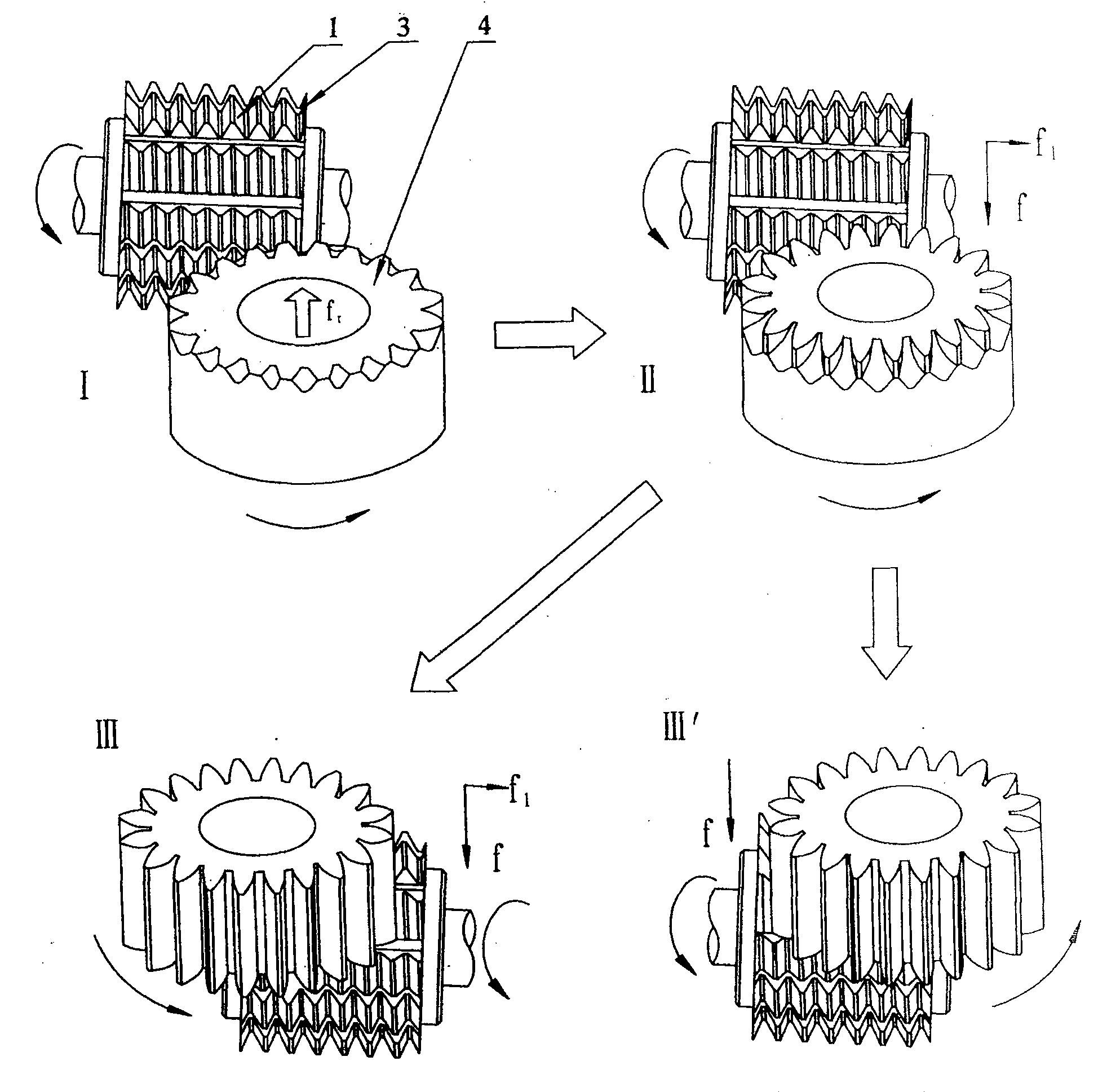
图6、本发明滚齿方法步骤示意图:I、径向不完整齿滚切,II、角向完整齿滚切,III、角向滚切全齿宽,III′、轴向滚切全齿宽。Fig. 6. Schematic diagram of the steps of the gear hobbing method of the present invention: I, radial hobbing of incomplete teeth, II, angular hobbing of complete teeth, III, angular hobbing of full tooth width, III', axial hobbing of full tooth width .
具体实施方式 Detailed ways
下面结合附图对本发明的实施例作进一步描述。Embodiments of the present invention will be further described below in conjunction with the accompanying drawings.
不完整齿3虽不能最终展成包络齿轮完整的齿形,但对于齿槽的粗切加工却十分有利,因不完整齿3部分不但十分锋利,且其齿高的递增在滚刀端截面上呈现出图2所示的阿基米德螺旋线2,使得滚切时刀齿是逐渐切深的,刀齿的负荷分布均匀,因此对于起始粗切不完整齿来讲,滚刀两端的不完整齿3是完全能胜任,且是可以利用的。Although the
方法步骤:I、径向不完整滚切:Method steps: 1, radial incomplete hobbing:
滚切前,按加工工件齿轮及滚刀的参数计算调整滚刀1与工件4的相对位置,需将滚刀轴中心线和滚刀端面的交点与工件端平面保持一定的距离h,如图5I所示,滚刀抬高高度h要满足角向滚齿时,滚刀的有效完整齿部分的啮合展成中心5与工件4端面平齐时,能包络出有效、完整的齿轮轮齿,如图5II所示。Before hobbing, calculate and adjust the relative position of
K×mn为安全距离,K为安全系数,mn×π为齿轮一完整齿距,mn为法向模数,f、f1为轴向及切向进给量,h与滚刀外径无关,主要与加工齿轮参数及角向进给比例有关;K × m n is the safety distance, K is the safety factor, m n × π is the complete tooth pitch of the gear, m n is the normal modulus, f, f 1 is the axial and tangential feed, h and the hob The outer diameter is irrelevant, mainly related to the processing gear parameters and the ratio of angular feed;
滚刀1的一个端平面上的不完整齿3与滚刀外径母线的交点对准工件的轴线中心作切入点,如图6I所示,工件4朝fr方向径向进给至全齿深,由于滚刀中心高于工件上端面,切出的齿形不完整,这时虽用滚刀1的不完整齿3参与切削,因初始加工对齿形无任何影响,相反可以加大径向进给量,即使刀齿磨损也不会影响齿形,滚齿时间为
II、角向完整齿滚切:II. Angular full gear hobbing:
紧接上述全齿深加工后,再进行角向滚齿,如图6II所示,滚刀1按轴向f和切向f1方向进给,当滚刀有效、完整的齿啮合展成中心5与工件上端面平齐时,切出完整的齿形,滚齿时间为TII;Immediately after the deep machining of the above-mentioned full teeth, the angular hobbing is carried out. As shown in Fig. 6II, the
III、角向滚切全齿宽:III. Full tooth width of angular hobbing:
紧接上述切出完整的齿形后,再进行角向滚齿,如图6III所示,滚刀按轴向f和切向f1方向进给,直至切出全齿宽,工件4加工成,用上述步骤加工成的齿轮最好,滚齿时间为TIII Immediately after the complete tooth shape is cut out above, the angular hobbing is carried out, as shown in Figure 6III, the hob is fed in the direction of axial f and tangential f 1 until the full tooth width is cut, and the
但在实际生产中受到滚刀长度的限制,滚刀轴向移动距离及工件齿宽三因素的制约限制,若不能采用上述的角向滚齿切完全齿时,可在结束图6II加工后,由角向滚齿变为轴向滚齿;However, in actual production, it is limited by the length of the hob, the axial movement distance of the hob and the tooth width of the workpiece. If the above-mentioned angular hobbing cannot be used to cut the complete tooth, after the processing in Figure 6II is completed, From angular hobbing to axial hobbing;
III′、轴向滚切全齿宽:III', axial hobbing full tooth width:
紧接上述切出完整的齿形后,由角向滚齿变为轴向滚齿,滚刀按轴向f方向进给直至切出全齿宽,如图6III′所示,滚齿时间为TIII′,Immediately after the complete tooth shape is cut out above, the angular hobbing is changed to axial hobbing, and the hob is fed in the axial f direction until the full tooth width is cut, as shown in Figure 6III′, the hobbing time is T III′ ,
IV、当滚刀1一端的不完整齿3经过一段时间使用后,可将滚刀调头安装,通过改变滚刀的旋转方向或铣削方向再按I、II、III或III′步骤加工,这时仍使用步骤I中的h,不用再计算,就可达到完全利用滚刀两端不完全齿的目的。IV. When the
在普通滚齿机上,只要具备切向刀架,就可实施此综合法加工齿轮。On an ordinary gear hobbing machine, as long as it has a tangential tool holder, this comprehensive method can be used to process gears.
数控滚齿机具备轴向、径向、切向加工的功能,随着数控滚齿机的普及应用,利用数控滚齿机使滚刀完全利用的综合滚齿方法成为可能。The CNC gear hobbing machine has the functions of axial, radial and tangential processing. With the popularization and application of the CNC gear hobbing machine, it is possible to use the CNC gear hobbing machine to make the comprehensive gear hobbing method that the hob fully utilizes.
实施例Example
加工一法向模数mn=2mm,齿数Z=20,齿宽b=30mm,切深g=4.5的正齿轮。Process a spur gear with normal modulus m n =2mm, number of teeth Z=20, tooth width b=30mm, depth of cut g=4.5.
滚刀外径d=100mm,滚刀头数Z0=1Hob outer diameter d=100mm, number of hob heads Z 0 =1
加工工艺:滚刀转速n=400转/分安全系数k=0.2Processing technology: hob speed n=400 rpm safety factor k=0.2
轴向进给量f=0.66毫米/转Axial feed f=0.66 mm/rev
切向进给量f1=0.22毫米/转Tangential feed f 1 =0.22 mm/rev
径向进给量fr=1.2毫米/转Radial feed f r = 1.2mm/rev
滚刀抬高:Reel Elevation:

滚齿时间:T=TI+TII+III(或III′) Hobbing time: T = T I + T II + III (or III')

Claims (1)
Priority Applications (1)
| Application Number | Priority Date | Filing Date | Title |
|---|---|---|---|
| CNB2007100713649A CN100525976C (en) | 2007-09-20 | 2007-09-20 | Hob complete utilization integrated gear hobbing method |
Applications Claiming Priority (1)
| Application Number | Priority Date | Filing Date | Title |
|---|---|---|---|
| CNB2007100713649A CN100525976C (en) | 2007-09-20 | 2007-09-20 | Hob complete utilization integrated gear hobbing method |
Publications (2)
| Publication Number | Publication Date |
|---|---|
| CN101121210A CN101121210A (en) | 2008-02-13 |
| CN100525976C true CN100525976C (en) | 2009-08-12 |
Family
ID=39083820
Family Applications (1)
| Application Number | Title | Priority Date | Filing Date |
|---|---|---|---|
| CNB2007100713649A Expired - Fee Related CN100525976C (en) | 2007-09-20 | 2007-09-20 | Hob complete utilization integrated gear hobbing method |
Country Status (1)
| Country | Link |
|---|---|
| CN (1) | CN100525976C (en) |
Families Citing this family (10)
| Publication number | Priority date | Publication date | Assignee | Title |
|---|---|---|---|---|
| CN102133663B (en) * | 2010-01-21 | 2013-05-08 | 无锡市瑞尔精密机械股份有限公司 | Gear hobbing method for protecting hobbing cutter during hobbing of spline shaft |
| DE102012012617A1 (en) * | 2012-06-19 | 2013-12-19 | Gleason-Pfauter Maschinenfabrik Gmbh | A method of generating a gearing and gearing machine operable with this method |
| CN103846507B (en) * | 2012-12-04 | 2017-01-25 | 中车戚墅堰机车车辆工艺研究所有限公司 | Hobbing processing method of gear |
| CN104368880B (en) * | 2013-08-13 | 2016-09-14 | 南车戚墅堰机车车辆工艺研究所有限公司 | A kind of tangential admission hobbing method for gear-hobbing machine |
| WO2015115562A1 (en) * | 2014-02-03 | 2015-08-06 | シチズンホールディングス株式会社 | Machining device and machining method |
| DE102015104500A1 (en) * | 2015-03-25 | 2016-09-29 | Profilator Gmbh & Co. Kg | Method and device for gear cutting of gears by skiving |
| CN110471365B (en) * | 2019-01-08 | 2022-09-27 | 韶能集团韶关宏大齿轮有限公司 | Method for machining drum-shaped spline |
| CN112548597B (en) * | 2020-11-30 | 2021-10-08 | 重庆机床(集团)有限责任公司 | Numerical control slot milling machine tool rest capable of automatically centering |
| CN116339235B (en) * | 2023-03-29 | 2025-09-30 | 浙江陀曼智能科技股份有限公司 | A method and system for optimizing tool shifting of gear hobbing machine based on machining travel distance |
| CN118951171B (en) * | 2024-10-17 | 2025-01-03 | 四川普什宁江机床有限公司 | K-type gear hobbing method, device and medium |
-
2007
- 2007-09-20 CN CNB2007100713649A patent/CN100525976C/en not_active Expired - Fee Related
Also Published As
| Publication number | Publication date |
|---|---|
| CN101121210A (en) | 2008-02-13 |
Similar Documents
| Publication | Publication Date | Title |
|---|---|---|
| CN100525976C (en) | Hob complete utilization integrated gear hobbing method | |
| CN201446313U (en) | Pre-grind hob for machining hard tooth surface gear | |
| CN101774029B (en) | Method for turning helical surface of enveloping worm | |
| CN103692025B (en) | A kind of overlikon spiral bevel gear processing method | |
| CN108602144A (en) | Device and method for manufacturing chamfered edge on workpiece wheel with teeth | |
| CN102451938B (en) | Numerical milling processing threaded cutter, and processing method thereof | |
| CN101298107A (en) | Steep-pitch thread fabrication technique | |
| CN102303127B (en) | Method for removing incomplete thread by turning of numerically controlled lathe | |
| CN102441711B (en) | Single-side edge tooth cutting tool for cylindrical gear | |
| CN104653749B (en) | Gear with large tooth lead modification quantity and processing method thereof | |
| CN101439461B (en) | Technique for producing and processing chamfering tool for cylindrical gear double-side tooth profile | |
| CN105252029A (en) | Improved thread blade and implementation method thereof | |
| CN110524060B (en) | Method and device for machining duplex gear by numerical control milling machine | |
| CN102350526B (en) | Milling method of taper milling cutter with equal spiral angle and equal front angle | |
| CN111687495A (en) | Stepped feed rough cutting method for herringbone gear with narrow clearance groove | |
| CN100522438C (en) | Method for shaping gear shaver | |
| CN104889461A (en) | All-metal screw pump rotor milling method and device | |
| CN110560793B (en) | Hobbing cutter for machining straight bevel gears and manufacturing method thereof | |
| CN101066568A (en) | Elliptical internal gear hob | |
| CN103223533A (en) | Method for designing side rear angle surfaces of double-enveloping ring surface worm gear hob | |
| CN203184773U (en) | Front gear grinding hob | |
| CN100537099C (en) | A Two-tooth Difference Cycloidal Hob | |
| CN107116346A (en) | A kind of method for fine finishing of spiral bevel gear | |
| CN111687494A (en) | Method for generating and processing zero-degree rack of herringbone gear with narrow clearance groove | |
| CN113600932B (en) | Method for processing cylindrical helical gear by hobbing on bevel gear milling machine |
Legal Events
| Date | Code | Title | Description |
|---|---|---|---|
| C06 | Publication | ||
| PB01 | Publication | ||
| C10 | Entry into substantive examination | ||
| SE01 | Entry into force of request for substantive examination | ||
| C14 | Grant of patent or utility model | ||
| GR01 | Patent grant | ||
| ASS | Succession or assignment of patent right |
Owner name: NINGBO XIASHA GEAR CO., LTD. Free format text: FORMER OWNER: XIA JIANMIN Effective date: 20091225 |
|
| C41 | Transfer of patent application or patent right or utility model | ||
| TR01 | Transfer of patent right |
Effective date of registration: 20091225 Address after: Zhejiang province Ningbo Zhenhai Camel Industrial Zone No. 389 Ji Lu Rong Ningbo Xiasha gears Co Ltd Patentee after: Ningbo Xiasha Gears Co., Ltd. Address before: Zhejiang Province, Ningbo City Industrial Zone, Rong Ji Road camel Ningbo Xiasha gears Co Ltd Patentee before: Xia Jianmin |
|
| C17 | Cessation of patent right | ||
| CF01 | Termination of patent right due to non-payment of annual fee |
Granted publication date: 20090812 Termination date: 20130920 |