CN100537862C - Method and device for restarting a previously interrupted spinning process - Google Patents
Method and device for restarting a previously interrupted spinning process Download PDFInfo
- Publication number
- CN100537862C CN100537862C CNB2004800329526A CN200480032952A CN100537862C CN 100537862 C CN100537862 C CN 100537862C CN B2004800329526 A CNB2004800329526 A CN B2004800329526A CN 200480032952 A CN200480032952 A CN 200480032952A CN 100537862 C CN100537862 C CN 100537862C
- Authority
- CN
- China
- Prior art keywords
- channel
- fiber
- yarn
- drafting
- spinning device
- Prior art date
- Legal status (The legal status is an assumption and is not a legal conclusion. Google has not performed a legal analysis and makes no representation as to the accuracy of the status listed.)
- Expired - Fee Related
Links
Images


Classifications
-
- D—TEXTILES; PAPER
- D01—NATURAL OR MAN-MADE THREADS OR FIBRES; SPINNING
- D01H—SPINNING OR TWISTING
- D01H4/00—Open-end spinning machines or arrangements for imparting twist to independently moving fibres separated from slivers; Piecing arrangements therefor; Covering endless core threads with fibres by open-end spinning techniques
- D01H4/02—Open-end spinning machines or arrangements for imparting twist to independently moving fibres separated from slivers; Piecing arrangements therefor; Covering endless core threads with fibres by open-end spinning techniques imparting twist by a fluid, e.g. air vortex
-
- D—TEXTILES; PAPER
- D01—NATURAL OR MAN-MADE THREADS OR FIBRES; SPINNING
- D01H—SPINNING OR TWISTING
- D01H1/00—Spinning or twisting machines in which the product is wound-up continuously
- D01H1/11—Spinning by false-twisting
- D01H1/115—Spinning by false-twisting using pneumatic means
-
- D—TEXTILES; PAPER
- D01—NATURAL OR MAN-MADE THREADS OR FIBRES; SPINNING
- D01H—SPINNING OR TWISTING
- D01H15/00—Piecing arrangements ; Automatic end-finding, e.g. by suction and reverse package rotation; Devices for temporarily storing yarn during piecing
- D01H15/002—Piecing arrangements ; Automatic end-finding, e.g. by suction and reverse package rotation; Devices for temporarily storing yarn during piecing for false-twisting spinning machines
Landscapes
- Engineering & Computer Science (AREA)
- Mechanical Engineering (AREA)
- Textile Engineering (AREA)
- Spinning Or Twisting Of Yarns (AREA)
Abstract
本发明涉及一种用于在一个纺纱装置上重新开始先前中断了的纺纱过程的方法和装置,该纺纱装置包含一个可以停止的牵伸机构和一个具有负压室的空气喷嘴机构。在此将一种由重新投入运行的牵伸机构所供给的短纤维须条在离开牵伸机构之后,为了排除开始时非均匀的纤维流而暂时地通过一个偏转机构作为废料抽吸掉。只是在形成一种均匀的纤维流之后才使短纤维须条与运输穿过空气喷嘴机构的纱线相连接。同时规定,在存在于负压室里的负压的共同作用下排除非均匀的纤维流。

This invention relates to a method and apparatus for restarting a previously interrupted spinning process on a spinning apparatus comprising a stopable drafting mechanism and an air nozzle mechanism with a negative pressure chamber. A short fiber sliver supplied by the restarted drafting mechanism is temporarily sucked away as waste material by a deflection mechanism after leaving the drafting mechanism to eliminate the initial non-uniform fiber flow. Only after a uniform fiber flow is formed is the short fiber sliver connected to the yarn transported through the air nozzle mechanism. It is also stipulated that the non-uniform fiber flow is eliminated under the combined action of the negative pressure present in the negative pressure chamber.
Description
技术领域 technical field
本发明涉及一种用于在纺纱装置上重新开始先前中断的纺纱过程的方法,该纺纱装置包含一个可停止的牵伸机构和一个具有负压室的空气喷嘴机构,其中使一个由重新投入运行的牵伸机构所供给的短纤维须条在离开牵伸机构之后,为了排除开始时非均匀的纤维流而暂时地通过一个偏转机构作为废料抽吸掉,而且只是在形成一种均匀的纤维流之后才使短纤维须条与运输穿过空气喷嘴机构的纱线连接。The invention relates to a method for restarting a previously interrupted spinning process on a spinning device comprising a stoppable drafting unit and an air nozzle unit with a negative pressure chamber, wherein a After leaving the drafting mechanism, the short fiber strands supplied by the drafting mechanism that has been put into operation are temporarily sucked off as waste through a deflection mechanism in order to eliminate the initially non-uniform fiber flow, and only in the formation of a uniform flow. The staple fiber strands are connected to the yarn transported through the air nozzle mechanism only after the fiber flow.
背景技术 Background technique
本发明也涉及一种用于实施该方法的纺纱装置,它具有一个在纺纱过程中断时可以停止的牵伸机构,具有一个带有纤维输入通道、纱线拉出通道和负压室的空气喷嘴机构,以及具有一个偏转机构,用于暂时地将从牵伸机构所供给的短纤维须条从与它要连接的纱线处偏移开。The invention also relates to a spinning device for carrying out the method, which has a drafting mechanism that can be stopped when the spinning process is interrupted, has a fiber inlet channel, a yarn withdrawal channel and a negative pressure chamber. The air nozzle mechanism also has a deflection mechanism for temporarily deflecting the short fiber strand supplied from the drafting mechanism from the yarn to be connected with it.
这种类型的方法和装置的现有技术为WO 94/00626 A1。该文献一般地涉及到喷气纺纱装置,并不涉及其特殊的结构方案,并且涉及之前中断了的纺纱过程的重新开始,例如此时由于某种原因而纱线发生破断。在这种情况下必须在纺纱过程中断之后使一个已经纺成的纱线的端头首先返回至牵伸机构。然后可以使已停止的牵伸机构又重新投入运行,并使新供给的短纤维须条与纱线端头连接。因为在中断时、而且在牵伸机构因此停止时就已使短纤维须条在牵伸机构里撕断了,因此在牵伸机构又起动时产生一种在其起始部分上首先是相对来说非均匀的短纤维须条。由于这个原因在已知的方法中和在已知的纺纱装置中规定,使开始时非均匀的纤维暂时作为废料被抽吸出来,并且并不是立即与返回至牵伸机构的纱线端头连接。只是在形成一种均匀的纤维流之后才使短纤维须条与运输穿过喷气组合件的纱线连接。因此对于重新又供给的短纤维须条与纱线的连接来说、即所谓接线,使接头具有明显改善的质量,也就是说其方法是:并不使短纤维须条的一个随意的由于撕断而形成的起始部分、而是短纤维须条的一个新形成的起始部分与纱线连接,其中新的起始部分由一种又是均匀的纤维流产生。此处一个位于牵伸机构和空气喷嘴机构之间的吸管用于暂时地抽吸该非均匀的纤维流。The prior art for methods and devices of this type is WO 94/00626 A1. This document relates generally to air-jet spinning devices, not to their specific design, and to the restart of a previously interrupted spinning process, for example when the yarn breaks for some reason. In this case, an already spun yarn end must first be returned to the drafting mechanism after the spinning process has been interrupted. The drafting mechanism that has stopped can then be put into operation again, and the staple fiber strands that are newly supplied are connected with the end of the yarn. Because the short fiber strands have been torn off in the drafting mechanism during the interruption, and when the drafting mechanism is therefore stopped, a relative at first on its initial part occurs when the drafting mechanism starts again. Said non-uniform staple fiber sliver. For this reason, in the known method and in the known spinning device, it is stipulated that initially non-uniform fibers are temporarily sucked out as waste and are not immediately returned to the yarn end of the drafting mechanism. connect. Only after forming a uniform fiber flow, the staple fiber strands are connected with the yarn transported through the air jet assembly. Therefore, for the connection of the staple fiber strand and the yarn supplied again, the so-called splicing, the joint has a significantly improved quality, that is to say, the method is: not to make a random staple fiber strand due to tearing Instead, a newly formed starting part of the staple fiber strand is connected to the yarn, wherein the new starting part is produced by a again uniform fiber flow. Here, a suction pipe between the drafting unit and the air nozzle unit is used to temporarily suck up the inhomogeneous fiber flow.
通过不属于这种类型的EP 0 807 699 B1已经公开了在一种完全特殊的喷气纺纱装置中短纤维须条在一个纱线端部上的接线。在这种纺纱装置中拉伸的短纤维须条经过喷气组合件的纤维输入通道首先进入一个涡流室里,该涡流室配置有一个流体机构,用于产生一个围绕着纱线拉出通道的一个入口开孔的涡流。同时首先使保持在短纤维须条里的纤维的前端头导入到纱线拉出通道里,而后边的自由纤维端头则展开,被涡流抓住并围绕已经位于纱线拉出通道的入口开孔里的、也就是织入的前端头旋转过来,因此产生了一种具有很大程度上真正加捻的纱线。同样在这种已知的纺纱装置中在牵伸机构重新投入运行之后首先将供给的短纤维须条的起始部分抽吸出,然而同样也吸入一个位于牵伸机构和空气喷嘴组合件之间的吸管里并且除此之外与纱线端头一起,短纤维须条应该与该端头连接。短纤维须条的起始部分和返回至牵伸机构的纱线端头也就是说暂时地缓冲存放在同一个抽吸机构里。因此就形成一种抽吸出的短纤维须条与同样也抽吸出的纱线的相对随意的连接,其中并不是有目标地力求一种质量良好的接线位置。在一种实际构造的这种型式的纺纱装置中因此(这在文献中未述及)设有一个捻接装置,它使接头在短纤维须条连接于纱线上之后后来又分离出来,并用一个更高质量的捻接点来替代。Already disclosed by EP 0 807 699 B1 not belonging to this type in a kind of completely special air-jet spinning device, the connection of staple fiber strands on a yarn end. The staple fiber strand drawn in this spinning device passes through the fiber input channel of the air jet assembly first into a vortex chamber, which is equipped with a fluid mechanism for generating a flow around the yarn withdrawal channel. A vortex of the inlet opening. Simultaneously at first the front end of the fiber that remains in the staple fiber sliver is introduced into the yarn draw-out channel, while the free fiber end at the back then spreads out, is caught by the eddy current and opens around the entrance already positioned at the yarn draw-out channel The front end in the hole, that is to say the weaving, is rotated, so that a yarn with a large degree of true twist is produced. Also in this known spinning device, after the drafting mechanism is put into operation again, at first the initial part of the supplied short fiber strand is sucked out, but also sucks in an element located between the drafting mechanism and the air nozzle assembly. In the straw between and otherwise together with the yarn end to which the staple fiber strands should be connected. The starting part of the staple fiber sliver and the end of the yarn that is returned to the drafting mechanism are temporarily buffered and stored in the same suction mechanism. This results in a relatively random connection of the aspirated staple fiber strands to the likewise aspirated yarn, wherein a splicing position of good quality is not targeted. Therefore (this is not described in the document) in the spinning device of this type of a kind of actual construction, be provided with a splicing device, it makes the splicing after the short fiber strand is connected on the yarn and then separates again, And replace it with a higher quality splice.
发明内容 Contents of the invention
本发明的任务是:在开头所述类型的一种方法和一种纺纱装置中以特别有效的方式产生一种均匀的纤维流并紧接着使短纤维须条与纱线端头连接。The object of the present invention is to generate a uniform fiber flow in a particularly efficient manner in a method and a spinning device of the type mentioned at the outset and to subsequently connect the staple fiber strands to the yarn ends.
该任务在该方法中如此解决:在存在于负压室里负压的共同作用下排除非均匀的纤维流。This object is solved in the method in that an inhomogeneous fiber flow is removed under the combined effect of the vacuum present in the vacuum chamber.
相应地在纺纱装置中如下来解决该任务:使负压室包括在偏转机构里,该负压室可通过一个连接通道与牵伸机构相连。Accordingly, this task is solved in the spinning device by including a vacuum chamber in the deflection mechanism, which vacuum chamber can be connected to the drafting mechanism via a connecting channel.
通过本发明的特征使非均匀的纤维流并不通过一个外部的抽吸机构而偏转离开,而是充分利用了纺纱装置的一个反正就有的机构用于排出非均匀的纤维流。在正常的纺纱运行时,在空气喷嘴机构中必需有负压室,以便排出输入给涡流室的压缩空气并同时将这种纺纱方法中不能避免的纤维下脚料运出。按照本发明可以充分利用这种负压,使非均匀的纤维流开始时从纱线的端头偏转离开,均匀的纤维流应该与该纱线端头相连。有利地使按照运行时存在于负压室里的负压暂时地提高以排除非均匀的纤维流。因此非均匀的纤维流可以更容易地从按照运行时的运输行程上(如它在正常纺纱过程中存在的那样)偏转离开。通过正确地调整时间,可以使均匀纤维流的起始部分与纱线端头的搭接位置保持很短,从而只产生一个小的粗节,这种粗节可以看作为可接受的疵点,这种疵点在最终产品中、例如一种织物里并不显露出来。Due to the features of the invention, the inhomogeneous fiber flow is not deflected away by an external suction device, but an already existing device of the spinning device is used to discharge the inhomogeneous fiber flow. During normal spinning operation, negative pressure chambers are necessary in the air nozzle mechanism in order to discharge the compressed air supplied to the vortex chamber and simultaneously remove the unavoidable fiber waste in this spinning method. According to the invention, this underpressure can be exploited to the extent that a non-uniform fiber flow is initially deflected away from the yarn end to which a uniform fiber flow should be connected. Advantageously, the vacuum prevailing in the vacuum chamber during operation is temporarily increased in order to eliminate an inhomogeneous fiber flow. A non-uniform fiber flow can thus be deflected more easily from the transport path during operation (as it exists during normal spinning). By adjusting the timing correctly, the overlap between the beginning of the uniform fiber flow and the end of the yarn can be kept very short, resulting in only a small thick place, which can be regarded as an acceptable defect. This defect does not show up in the final product, such as a fabric.
在一种变型方案中,使短纤维须条在空气喷嘴机构内部偏离运行时的运输行程。非均匀的纤维流因此首先如同在正常纺纱运行时进入到空气喷嘴机构的内部中,但在那里作为废料暂时地被偏转离开。因此也在空气喷嘴机构的内部中使均匀化的纤维流在纱线端头上接线,如果暂时提高的负压又被降低到对于纺纱运行来说正常的大小的话。In a variant, the short-fiber strands are deviated from the transport path during operation within the air nozzle mechanism. The inhomogeneous fiber flow therefore initially enters the interior of the air nozzle arrangement as in normal spinning operation, but is temporarily deflected away there as waste. A homogenized fiber flow is thus also brought into contact with the yarn end in the interior of the air nozzle arrangement, if the temporarily increased vacuum is reduced again to the normal magnitude for spinning operation.
在另一种变型方案中规定,使短纤维须条在牵伸机构和空气喷嘴机构之间偏离运行时的运输行程。非均匀的纤维流因此暂时地不在其正常的路径上进入到空气喷嘴机构的内部,而是暂时地以另外的方式进行。因此这是合理的,因为通入到空气喷嘴机构中的入口开孔的尺寸通常是很小的,并因此尤其在粗的纱线支数时和高的供给速度时可以使纤维材料连同接头纱线几乎不再按规定通过所述小的开孔引入。在这种情况下,局部地已在到达空气喷嘴机构之前就使均匀的纤维流与纱线端头结合起来。In another variant, it is provided that the short-fiber strands are deviated from the transport path during operation between the drafting device and the air nozzle device. The inhomogeneous fiber flow therefore temporarily does not enter the interior of the air nozzle mechanism on its normal path, but does so temporarily in another way. This is therefore justified, because the size of the inlet opening leading into the air nozzle mechanism is usually very small, and therefore it is possible to make the fiber material together with the piecing yarn especially at thick yarn counts and high feed speeds. The wires are almost no longer properly guided through the small openings. In this case, a uniform fiber flow is combined with the yarn end locally already before reaching the air nozzle mechanism.
为了使作为废料输出的非均匀的纤维流的数量尽可能地小,在本发明的方案中有利地规定了:在去除非均匀的纤维流时使短纤维须条的纤维材料减少。短纤维须条因此被牵伸机构首先以减小的供给速度输入,其中也是按这种方式由于短纤维须条偏离正常的运输行程而在一定的时间之后实现了一种均匀的纤维流。In order to keep the number of inhomogeneous fiber streams output as waste as low as possible, it is advantageously provided in the concept of the invention that the fiber material of the short-fiber strands be reduced when the inhomogeneous fiber streams are removed. The short-fiber strands are thus initially supplied by the drafting mechanism at a reduced feed speed, wherein also in this way a uniform fiber flow is achieved after a certain time due to the deviation of the short-fiber strands from the normal transport path.
尽管按照本发明使所要接线的纱线的返回至牵伸机构的端头直至通过牵伸机构的供给罗拉对而返回,但应该明确指出:可以使纱线的端头以适合的方式也保持在空气喷嘴机构和牵伸机构之间。Although according to the present invention the end of the yarn to be spliced is returned to the draft mechanism until it is returned by the pair of feed rollers of the draft mechanism, it should be clearly pointed out that the end of the yarn can also be kept in a suitable manner. Between the air nozzle mechanism and the drafting mechanism.
在按照本发明的纺纱装置中最好使负压室设有一个接口用于暂时地提高负压。这例如可以是一个抽吸接口,它可以与一个分开的负压源相连,该负压源或者是固定的或者设置在一个可移动的维护器具上。然而有利的是:接口包含一个可施加压缩空气的喷射通道。这是一种用于提高负压的特别和有效的方式,尤其是一种压缩空气喷射反正对于接线是适宜的。In the spinning device according to the invention, the vacuum chamber is preferably provided with a connection for temporarily increasing the vacuum. This can be, for example, a suction connection, which can be connected to a separate vacuum source, which is either stationary or arranged on a movable maintenance device. However, it is advantageous if the connection contains an injection channel to which compressed air can be applied. This is a special and effective way to increase the vacuum, especially a jet of compressed air is suitable for wiring anyway.
在所述与牵伸机构连接的负压室里,在一种变型方案中可以应用符合生产条件的纤维输入通道作为连接通道,纱线拉出通道可以最好与该纤维输入通道分离开。这是在没有大的额外费用情况下的一种简单的技术方案,尤其使纱线拉出通道与纤维输入通道分开,用于穿入纱线并用于清洗涡流室,反正是有利的。In the vacuum chamber connected to the drafting mechanism, in a variant, a production-compliant fiber feed channel can be used as a connection channel, from which the yarn withdrawal channel can preferably be separated. This is a simple technical solution without great additional effort, and it is in particular advantageous to separate the yarn withdrawal channel from the fiber input channel for threading the yarn and for cleaning the swirl chamber.
然而特别有利的是设有一个单独的旁路通道作为连接通道。该旁路通道在一种变型方案中合适地设置一个闭锁机构,该闭锁机构在正常纺纱工作时封闭了旁路通道、并且为了使非均匀的纤维流偏移开而释放开通。这种操纵在此可以通过一种可移动的维护器具来进行。However, it is particularly advantageous to provide a separate bypass channel as connecting channel. In a variant, the bypass channel is expediently provided with a locking mechanism which closes the bypass channel during normal spinning operation and releases it to deflect the non-uniform fiber flow. This manipulation can take place here by means of a movable maintenance tool.
在另一种变型方案中,设有一个在工作时指向牵伸机构的清洗通道作为旁路通道。在这种情况下不需要使旁路通道在工作时关闭,因为通过该旁路通道例如通过抽吸而使牵伸机构的供给罗拉对不断地清洗掉飞毛。为了使非均匀的纤维流偏转离开,则可以暂时地提高负压室里的负压,使纤维流能够容易地通过清洗通道而从其正常运输路径上偏转离开。In a further variant, a rinsing channel which is directed toward the drafting mechanism during operation is provided as a bypass channel. In this case, it is not necessary to close the bypass channel during operation, since the pair of supply rollers of the drafting mechanism are continuously cleaned of fly by this bypass channel, for example by suction. In order to deflect the inhomogeneous fiber flow away, the vacuum in the vacuum chamber can be temporarily increased, so that the fiber flow can easily be deflected away from its normal transport path through the cleaning channel.
附图说明 Description of drawings
本发明的其它优点和特征可以见以下对一些实施例的说明。附图所示为:Further advantages and features of the invention can be found in the following description of some embodiments. The accompanying drawings show:
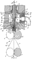
图1:一种纺纱装置在按照本发明的部位里在工作时的轴向剖视图;Fig. 1: Axial sectional view of a kind of spinning device when working in the position according to the present invention;
图2:在去除非均匀的纤维流时按图1所示的纺纱装置;Fig. 2: Spinning device according to Fig. 1 when removing non-uniform fiber flow;
图3:纺纱装置的另一种设计方案在去除非均匀的纤维流时的轴向剖视图;Fig. 3: Axial sectional view of another design of the spinning device when removing non-uniform fiber flow;
图4:在正常纺纱工作时按图3所示的纺纱装置;Figure 4: Spinning device shown in Figure 3 during normal spinning work;
图5:另一种纺纱装置在去除非均匀的纤维流时的一个轴向剖视图;Figure 5: An axial sectional view of another spinning device when removing non-uniform fiber flow;
图6:在工作时按图5所示的纺纱装置;Fig. 6: by the spinning device shown in Fig. 5 during work;
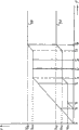
图7:表示出属于牵伸机构的供给罗拉的供给速度的图表。Figure 7: Diagram showing the feed speed of the feed rollers belonging to the drafting mechanism.
具体实施方式 Detailed ways
图1所示的纺纱装置处于正常纺纱运行的状态,它用于由短纤维须条2制造纺成的纱线1。纺纱装置包含一个牵伸机构3和一个空气喷嘴机构4。The spinning device shown in FIG. 1 is in normal spinning mode for producing spun
将待纺短纤维须条2在拉伸方向A上输送给牵伸机构3,作为已纺出的纱线1以未示出的纱线拉出罗拉在拉出方向B上拉出并继续运送至一个未示出的络纱机构上。只是局部示出的牵伸机构3优选是一个三罗拉牵伸机构,并因此包含总共三个罗拉对,它们分别具有一个被驱动的用阴影线表示的下罗拉和一个设计成施压罗拉的上罗拉。所示的只是供给罗拉对5,6以及一个布置在其前面的具有导向皮带9,10的皮带罗拉对7,8。在这样一种牵伸机构3里以已知的方式使短纤维须条2一直拉伸至所希望的细度。接着牵伸机构3就出来一种薄的小纤维带11,它被拉伸了但未加捻。The staple fiber sliver 2 to be spun is conveyed to the
通过一个纤维输入通道12将小纤维带11输送给空气喷嘴机构4。接着是一个所谓涡流室13,在其中使小纤维条11获得纺纱加捻,从而产生了纺成的纱线1,它穿过纱线拉出通道14被拉出。The
一个流体机构在纺纱过程期间在涡流室13里通过将压缩空气吹入穿过切向通入到涡流室13里的压缩空气喷嘴15而产生一种涡流。该由喷嘴孔流出的压缩空气通过一个通入到负压室16中的排气通道17被排出,其中该排气通道具有一个围绕着主轴形的、在工作时固定的构件18的环形横截面,该固定构件18里包含了纱线拉出通道14。A fluid mechanism generates a vortex in the
在涡流室13部位里设有纤维导向面19的一个棱边作为阻捻机构,它相对纱线拉出通道14略有偏心地布置在该纱线拉出通道的入口开孔20的部位处。In the area of the
在空气喷嘴机构4里使所要纺纱的纤维一方面保持在小纤维带11里,并这样从纤维输入通道12基本上无加捻地引入纱线拉出通道14里,但另一方面使纤维在纤维输入通道12和纤维拉出通道14之间的部位里经受涡流的作用。通过这种作用使纤维或者至少其端部从纱线拉出通道14的入口开孔20处径向移动离开。用所述纺纱装置制成的纱线1因此是基本在纱线纵向方向上延伸的、没有很大加捻的纤维或者纤维部位的芯线,而且是纤维或纤维部位围绕芯线捻转的一个外面部位。这种型式的纺纱装置允许有很高的纺纱速度,其大小在300至600米/分钟之间。In the
由压缩空气喷嘴15流出至涡流室13里的压缩空气在工作时通过一个压缩空气通道21在输入方向C上输送给空气喷嘴机构4。压缩空气从压缩空气通道21首先到达一个围住涡流室13的环形通道22,直接与之相连的是所述的压缩空气喷嘴15。The compressed air flowing out of the
在纱线拉出通道14的入口开孔20和纤维导向面19之间在符合生产条件的纺纱过程中存在一个很小的间距,它例如达0.5mm。该小间距如此来建立:包含了纱线拉出通道14的主轴状构件18可以移动地布置在轴向方向上。该间距可以在工作状态时固定住。为了在一个维护过程期间加大该间距,主轴状构件18局部设计成一个活塞缸体单元的活塞状构件。During the spinning process suitable for production conditions, there is a very small distance between the inlet opening 20 of the
如果由于任何什么原因使小纤维带11或者纱线1断了,那么首先使输给涡流室13的过压切断,可见图2中的打叉箭头C。同时使牵伸机构3以及未示出的纱线拉出罗拉和络纱机构的所有驱动机构都关断。If for any reason the
因为主轴状构件18局部设计成活塞,因此可以用很简单的措施使纱线拉出通道14运动离开纤维输入通道12。因此例如设有一个围住主轴状构件18的环形通道24,主轴状构件18穿过该环形通道而且该环形通道连接于压缩空气的一个输入管路25上。这种压缩空气,见图2的箭头D和图1中的打叉箭头D,只是在纺纱过程中断时才输入。那么进入环形通道24的压缩空气就使主轴状构件18在图2所示的视图里向上运动,从而由于活塞行程使环形通道24扩展成一个加大的环形室。一个固定装在主轴状构件18上的限制活塞23因此限定了工作时的环形通道24,并在纺纱过程中断时限定了加大的环形室。限制活塞23克服加载弹簧26而起作用,该加载弹簧在压缩空气切断时、也就是在纺纱时,将所述活塞状构件压入一个安全的工作位置上。因此通过输入管路25输入的压缩空气用于使纱线拉出通道14运动离开纤维输入通道12,相反,加载弹簧26则用于返回运动。Since the spindle-shaped
工作时在纤维导向面19和纱线拉出通道14的入口开孔20之间很小的间距可以通过在运行中断时主轴状构件18的运动离开而加大至一个间距,该间距可以使得位于纤维导向面19和入口开孔20之间的空间得到清洗。During operation, the very small distance between the fiber guide surface 19 and the inlet opening 20 of the
如果纱线拉出通道14与纤维输入通道12分开,那么就可以使纺成的纱线1的端头36与拉出方向B反向地返回至牵伸机构3,为此可见图2。为此设有一个第一注入通道27作为辅助机构,它可以连接于相同的压力源上,正如环形通道24及其入口连接于纱线拉出通道14上并指向其入口开孔20那样。因此在纱线拉出通道14里可以实现一个指向牵伸机构3的抽吸空气流,该抽吸空气流使纺成的纱线1的端头36返回至供给罗拉对5,6。If the
通过输入管路25输送给环形通道24的压缩空气,如图可见,不仅用于使主轴状构件18运动离开纤维输入通道12,而且同时也通过注入通道27产生注入空气流,该注入空气流可以使所要接线的纱线1的端头36穿引在短纤维须条2上。活塞状构件在一定程度上设计成阀门,该阀门在输入压缩空气时可以操纵,然后在输入管路25和注入通道27之间建立一种作用连接。The compressed air delivered to the
如果为了重新开始已中断的纺纱过程、使牵伸机构3和未示出的纱线拉出罗拉和络纱机构的驱动机构重新接通的话,如果没有采取特别的措施,那么在短纤维须条2和纱线1的端头36之间可能会形成一种质量差的接头。这就是说必须考虑到:在纺纱过程中断时短纤维须条2就在牵伸机构3里在导向皮带9,10和供给罗拉对5,6之间以相对来说不可控的方式撕断。短纤维须条2的重新提供的起始部分也就是说不具有必要的规则顺序,其中这种不规则还通过如下方法而翻倍:在皮带罗拉对7,8和供给罗拉对5,6之间产生大的拉伸。这就是说害怕在接线过程中材料的极端波动。因此首先规定了:排除掉开始的首先作为废物33的非均匀的纤维流32(见图2),也就是说直至短纤维须条2导至均匀的纤维流34为止(见图1)。非均匀的纤维流32因此通过一个所谓纤维流换接机构首先偏转离开,以便使这些不够长的纤维在临界的接线部位里不与纱线1的端头36连接。纤维流换接机构因此用于使开始负面的纤维材料的分布不影响接线过程。If in order to restart the interrupted spinning process, the
一种纤维流转换机构本质上已经如上所述那样通过开头所评价的现有技术而已知了。在这种已知的装置中,在供给罗拉对5,6和纤维输入通道12的入口之间设有一个外部的抽吸管,用于排出非均匀的纤维流。与之不同地是按照本发明规定了:对于偏转离开非均匀的纤维流32来说并不利用一种分开的外部负压源,而是用反正在空气喷嘴机构4中的负压室16。A fiber flow switching mechanism is already known per se from the prior art reviewed at the outset, as described above. In this known device, an external suction line is provided between the pair of
按照图1和2所示的实施方式使非均匀纤维流32作为废料33在空气喷嘴机构4的内部偏转离开。负压室16里的负压即使在运行中断时也保持住,而如前所述,通过压缩空气通道21的压缩空气输入则中断了。为使非均匀纤维流32可靠地远离所要接线的纱线1,在本发明的方案中规定了:符合生产条件的、存在于负压室16中的负压暂时被提高。因此可以使作为废料33要排除的纤维容易地通过一个接着的负压通道28在抽吸方向E上排出。如果在负压室16里的负压的暂时提高又终止了,并且同时使引入涡流室13的过压又输入的话,那么短纤维须条2的当前被输入的均匀纤维流34本身跟随着纱线1穿过纱线拉出通道14,其中产生了一种质量足够好的接线过程,该接线过程不需要在事后通过捻接连接而排除。如果纱线1的端头36准确地确定尺寸并且以已知的方式同样地也准备好,那么就可以控制该接线过程,从而使纱线1的端头36和短纤维须条2的起始部分之间的搭接位置是很短的。According to the embodiment shown in FIGS. 1 and 2 , the
暂时地提高负压室16里的负压可以按很多不同的方式来实现。按照本发明有利地设有一个接口30用于负压室16。该接口30可以包含一个可以施加压缩空气的第二注入通道29。为了排除非均匀的纤维流32,就要首先使一个压缩空气流通过接口30对应于箭头方向F进行输送,其中压缩空气首先到达一个环形通道31,然后到达第二注入通道29,该注入通道指向负压通道28并沿着抽吸方向E指向。因此负压室16里的负压大大提高,从而使非均匀的纤维流32以简单的方式从其符合生产条件的运输路程上、也就是从纱线拉出通道14处偏转离开。Temporarily increasing the vacuum in the
在按图1和2的实施方式中,将反正就存在的纤维输入通道12用作连接通道35。为了容易地在非均匀纤维流32和纱线1之间实现分离,使主轴状构件18运动离开纤维导向面19一小段距离,正如这在以前已描述过的那样,距离的大小只要使第一注入通道27还达不到环形通道24即可。纱线1由于其已经存在的强度就在运输方向G上运输穿过纱线拉出通道14。In the embodiment according to FIGS. 1 and 2 , the
从时间上这样来控制接线过程,使所述应该与均匀的纤维流34相连接的端头36,在非均匀的纤维流32完全排除掉时才到达涡流室13的部位。此时又使正常的低的在负压室16里的纺纱负压接通,并使压缩空气输送给涡流室13。此外当然必须使主轴状构件18又引导进入至其符合生产条件的部位里,这通过切断压缩空气流D来进行。The connection process is temporally controlled in such a way that the ends 36 which are to be connected to the
在以下所要描述的可选择的实施例中就不再重复说明这些单个构件,如果这些构件与图1和2中的相同的话。以下的说明因此限于那些在可选变型方案中与按图1和2所示的实施方式不同的构件。In the alternative embodiments to be described below, the description of these individual components will not be repeated if they are the same as in FIGS. 1 and 2 . The following description is therefore limited to those components which, in alternative variants, differ from the embodiment shown in FIGS. 1 and 2 .
在按图3和4的实施方式中使非均匀的纤维流32不是在空气喷嘴机构4的内部、而是在牵伸机构3的供给罗拉对5,6和空气喷嘴机构4之间就偏转离开。为此在牵伸机构3和负压室16之间设有一个旁路通道37作为连接通道,该旁路通道大致平行于纤维输入通道12、紧靠着其附近延伸。该旁路通道37通过一个闭锁机构38在运行时可以关闭,而在排除非均匀纤维流32时则可以暂时打开,例如通过一个可移动的维护器具来实现。图3表示了旁路通道37的开启状态,图4则表示了关闭的工作状态。由图3可见,非均匀纤维流32如何穿过该旁路通道37到达负压室16里,并从那里起到达负压通道28中、并沿着抽吸方向E被除去。同样在这种实施方式中实用的并因此规定的是:在排除非均质纤维流32时暂时地以已述方式提高负压室16里的负压。In the embodiment according to FIGS. 3 and 4 , the
如果特别是在粗纱线和高的供给速度时担心纤维输入通道12的入口在继续输入短纤维须条2时太小的话,那么按图3和4的实施方式就尤其是实用的。与之相反旁路通道37的开孔原则上可以设计得足够大。The embodiment according to FIGS. 3 and 4 is especially practical if, particularly at roving yarns and high feed speeds, there is concern that the inlet of the
为此还应指出,在所有以前所述的实施例中可以使空气喷嘴机构4在必要时从其工作位置上摆动离开,以便使非均匀纤维流32更容易偏转离开。To this end, it should also be pointed out that in all the previously described exemplary embodiments, the
同样在图5和6所示的实施方式中,为了排除非均匀的纤维流32设有一个分开的旁路通道,但它在这种情况下是不可关闭的,因为它即使在通常的纺纱运行时也具有一种功能。按照图5和6应用了一个指向牵伸机构3供给罗拉对5,6的清洗通道39作为旁路通道。Also in the embodiment shown in FIGS. 5 and 6, a separate bypass channel is provided to exclude a
在正常的纺纱运行时,如果在负压室16里有一种按照运行来说并不太高的负压,那么清洗通道39就用来连续地至少使通常用橡胶作成的施压罗拉6的圆周清除掉飞毛或其它的污染物。该清洗通道39按照本发明可以用来排除非均匀的纤维流32,这种纤维流作为废料33被排出至负压通道28里。为了排除非均匀的纤维流32,为此也使负压室16里的负压暂时地以已述的方式升高。因此又进行运输的短纤维须条2的纤维开始并不跟随纱线1进入到纤维输入通道12里,而是有一段距离地跟随施压罗拉6的圆周进入到清洗通道39里。During normal spinning operation, if in the
按照图7所示,说明了在接线过程中供给罗拉对5,6和皮带罗拉对7,8的速度。该速度在这里理解为短纤维须条2的运输速度,也就是罗拉对5,6或者7,8相应的圆周速度。According to Fig. 7, the speeds of the pair of
曲线40表示供给罗拉对5,6的速度v,曲线41表示皮带罗拉对7,8的速度v。此处应该先讲到:短纤维须条2在纺纱过程中断时由相应的驱动机构来控制,它已经在导向皮带9,10和供给罗拉对5,6之间被撕断了。Curve 40 represents the speed v of the pair of
按图7所示图表,横座标为时间T,纵座标为速度v。According to the chart shown in Fig. 7, the abscissa is time T, and the ordinate is speed v.
可以认为,在时间T1时接线过程通过重新接通供给罗拉对5,6的驱动机构而开始。由图可见,从时刻T1起供给罗拉对5,6的速度v按曲线40首先增加,也就是说一直提高至恒定的接线速度v1A,它在时刻TA时达到。从该时刻TA起供给罗拉对5,6首先以对于工作速度v1B来说是降低的、但恒定的接线速度v1A运行。It can be considered that the splicing process starts at time T1 by reactivating the drives of the pair of
因为皮带罗拉对7,8首先尚未重新起动,因此首先只使纱线1、而不是短纤维须条2在拉出方向B上运输。皮带罗拉对7,8的延迟起动是为了使纱线1的端头36到达一个规定的位置上,在该位置上应该进行真正的接线过程、也就是使均匀的纤维流34与纱线1的端头36相连。按照图7规定了:皮带罗拉对7,8在时刻T2时启动,也就是说相对于供给罗拉对5,6的启动有一定的迟后。Since the pair of
一旦皮带罗拉对7,8动作,短纤维须条2就开始运输,其起始部分则很快到达供给罗拉对5,6的钳口,然后同样也拉紧地通过供给罗拉对5,6运输。但短纤维须条2以已述的方式首先包含非均匀纤维流32,该纤维流应该以之前所述的方式偏转离开。在此为了不使大量的纤维作为废物33排出,首先规定使皮带罗拉对7,8尚未升高至接线速度v2A,而首先只是到达一个还继续下降了的中间速度v2B该中间速度v2B是在时刻T3和T4之间。在这段时间内排除了大部分废物33。在时刻T4时则使皮带罗拉对7,8升高至其在时刻TA时到达的接线速度v2A。Once the
一旦供给罗拉对5,6和皮带罗拉对7,8分别到达了其接线速度v1A和V2A,那就使最后一段非均匀纤维流32作为废物33排出。但紧跟着,在时刻TU,进行已述的纤维流转换,也就是说使负压室16里的提高了的负压又降低,并且使压缩空气通过压缩空气通道21引入到涡流室13中。因此自时刻TU起产生均匀的纤维流34,该纤维流自该时刻起占有其按照运行的运输行程。紧随其后,在时刻TD则发生真正的接线,也就是说使短纤维须条2的均匀起始部分与纱线1的端头36相连接。应该认为,接线过程整体上在时刻T5结束了。自该时刻T5起,因此既使供给罗拉对5,6也使皮带罗拉对7,8分别都升速至运行速度v1B和v2B。因而接线过程结束了。As soon as the pair of
Claims (13)
Applications Claiming Priority (2)
| Application Number | Priority Date | Filing Date | Title |
|---|---|---|---|
| DE10353317.6 | 2003-11-10 | ||
| DE10353317A DE10353317B4 (en) | 2003-11-10 | 2003-11-10 | Method and device for restoring a previously interrupted spinning process |
Publications (2)
| Publication Number | Publication Date |
|---|---|
| CN1878896A CN1878896A (en) | 2006-12-13 |
| CN100537862C true CN100537862C (en) | 2009-09-09 |
Family
ID=34559651
Family Applications (1)
| Application Number | Title | Priority Date | Filing Date |
|---|---|---|---|
| CNB2004800329526A Expired - Fee Related CN100537862C (en) | 2003-11-10 | 2004-07-30 | Method and device for restarting a previously interrupted spinning process |
Country Status (6)
| Country | Link |
|---|---|
| US (1) | US7464529B2 (en) |
| EP (1) | EP1682704A1 (en) |
| JP (1) | JP4350129B2 (en) |
| CN (1) | CN100537862C (en) |
| DE (1) | DE10353317B4 (en) |
| WO (1) | WO2005047580A1 (en) |
Cited By (1)
| Publication number | Priority date | Publication date | Assignee | Title |
|---|---|---|---|---|
| WO2012164435A1 (en) * | 2011-05-31 | 2012-12-06 | Lakshmi Machine Works Ltd. | An improved piecing mechanism in an air spinning machine |
Families Citing this family (17)
| Publication number | Priority date | Publication date | Assignee | Title |
|---|---|---|---|---|
| WO2006017948A1 (en) * | 2004-08-20 | 2006-02-23 | Maschinenfabrik Rieter Ag | Spindle having an injector channel and method for piecing up the yarn end in an air jet spinning machine |
| DE102004044345A1 (en) * | 2004-09-09 | 2006-03-16 | Wilhelm Stahlecker Gmbh | Air-jet spinning device |
| DE102005045703A1 (en) * | 2005-09-19 | 2007-03-22 | Wilhelm Stahlecker Gmbh | Air jet unit for an air jet spinning device |
| DE102007009074A1 (en) * | 2007-02-24 | 2008-08-28 | Oerlikon Textile Gmbh & Co. Kg | spinning device |
| DE102009034206A1 (en) * | 2009-07-17 | 2011-01-27 | Maschinenfabrik Rieter Ag | Component for an air jet spinning device |
| CH705221A1 (en) * | 2011-07-01 | 2013-01-15 | Rieter Ag Maschf | Roving for producing a roving and method for piecing a fiber association. |
| DE102011053812A1 (en) * | 2011-09-21 | 2013-03-21 | Rieter Ingolstadt Gmbh | Spinning machine and method for interrupting the production of yarn on a spinning machine |
| DE102011053813A1 (en) * | 2011-09-21 | 2013-03-21 | Maschinenfabrik Rieter Ag | Spinning machine and method for discharging an end portion of a yarn on a spinning machine before a subsequent piecing |
| DE102011053811A1 (en) * | 2011-09-21 | 2013-03-21 | Rieter Ingolstadt Gmbh | Spinning machine and method for interrupting the production of yarn on a spinning machine |
| DE102012100674A1 (en) * | 2012-01-27 | 2013-08-01 | Maschinenfabrik Rieter Ag | Air-jet spinning machine with a cleaning member and method for cleaning the swirl chamber of an air-jet spinning machine |
| CH709953A1 (en) * | 2014-07-30 | 2016-02-15 | Rieter Ag Maschf | Method for operating an air spinning machine. |
| CH712663A1 (en) * | 2016-07-14 | 2018-01-15 | Rieter Ag Maschf | Process for processing a strand-like fiber composite and roving machine. |
| DE102018131767A1 (en) * | 2018-12-11 | 2020-06-18 | Saurer Spinning Solutions Gmbh & Co. Kg | Textile machine producing cross-wound bobbins |
| DE102019120592A1 (en) * | 2019-07-30 | 2021-02-04 | Maschinenfabrik Rieter Ag | Method for piecing a spinning nozzle of an air-jet spinning machine and air-jet spinning machine |
| CN111041727B (en) * | 2019-12-31 | 2020-09-22 | 艾百合纺织科技(安徽)有限公司 | Embroidery broken yarn on-line wiring device |
| LU503239B1 (en) * | 2022-12-22 | 2024-06-24 | Saurer Intelligent Technology AG | Spinning station of an air spinning machine and method for carrying out a piecing process at such a spinning station |
| LU503240B1 (en) * | 2022-12-22 | 2024-06-24 | Saurer Intelligent Technology AG | Sliver preparation |
Citations (4)
| Publication number | Priority date | Publication date | Assignee | Title |
|---|---|---|---|---|
| WO1994000626A1 (en) * | 1992-06-25 | 1994-01-06 | Maschinenfabrik Rieter Ag | Process and device for automatically attaching yarn to be spun to the end of existing yarn |
| CN1117095A (en) * | 1994-01-25 | 1996-02-21 | 村田机械株式会社 | Yarn connecting method of spinning machine |
| CN1165879A (en) * | 1996-05-16 | 1997-11-26 | 村田机械株式会社 | Connecting method and device of spinning machinery |
| CN1407153A (en) * | 2001-09-05 | 2003-04-02 | 村田机械株式会社 | Spinning devices |
Family Cites Families (6)
| Publication number | Priority date | Publication date | Assignee | Title |
|---|---|---|---|---|
| DE2720519C2 (en) * | 1977-05-06 | 1983-06-23 | Toray Industries, Inc., Tokyo | Method and device for starting the spinning process when producing a yarn from staple fibers |
| JPS6047939B2 (en) * | 1981-10-22 | 1985-10-24 | 村田機械株式会社 | Yarn end guide method in pneumatic spinning device |
| JPH0748673Y2 (en) * | 1992-02-19 | 1995-11-08 | 村田機械株式会社 | Spinning equipment |
| JP2708000B2 (en) * | 1995-02-10 | 1998-02-04 | 村田機械株式会社 | Spinning equipment |
| DE10311826A1 (en) * | 2003-03-13 | 2004-09-23 | Wilhelm Stahlecker Gmbh | Yarn spinner, using staple fiber slivers, has an eddy chamber for the drawn sliver with an air extraction channel and a drawing unit cleaning channel, both connected to a common underpressure source |
| JP3925533B2 (en) * | 2004-11-05 | 2007-06-06 | 村田機械株式会社 | Spinning apparatus and fiber accumulation state detection method |
-
2003
- 2003-11-10 DE DE10353317A patent/DE10353317B4/en not_active Expired - Fee Related
-
2004
- 2004-07-30 US US10/578,919 patent/US7464529B2/en not_active Expired - Fee Related
- 2004-07-30 WO PCT/EP2004/008603 patent/WO2005047580A1/en not_active Ceased
- 2004-07-30 JP JP2006538663A patent/JP4350129B2/en not_active Expired - Fee Related
- 2004-07-30 CN CNB2004800329526A patent/CN100537862C/en not_active Expired - Fee Related
- 2004-07-30 EP EP04741341A patent/EP1682704A1/en not_active Withdrawn
Patent Citations (4)
| Publication number | Priority date | Publication date | Assignee | Title |
|---|---|---|---|---|
| WO1994000626A1 (en) * | 1992-06-25 | 1994-01-06 | Maschinenfabrik Rieter Ag | Process and device for automatically attaching yarn to be spun to the end of existing yarn |
| CN1117095A (en) * | 1994-01-25 | 1996-02-21 | 村田机械株式会社 | Yarn connecting method of spinning machine |
| CN1165879A (en) * | 1996-05-16 | 1997-11-26 | 村田机械株式会社 | Connecting method and device of spinning machinery |
| CN1407153A (en) * | 2001-09-05 | 2003-04-02 | 村田机械株式会社 | Spinning devices |
Cited By (1)
| Publication number | Priority date | Publication date | Assignee | Title |
|---|---|---|---|---|
| WO2012164435A1 (en) * | 2011-05-31 | 2012-12-06 | Lakshmi Machine Works Ltd. | An improved piecing mechanism in an air spinning machine |
Also Published As
| Publication number | Publication date |
|---|---|
| US7464529B2 (en) | 2008-12-16 |
| EP1682704A1 (en) | 2006-07-26 |
| DE10353317A1 (en) | 2005-06-09 |
| JP4350129B2 (en) | 2009-10-21 |
| WO2005047580A1 (en) | 2005-05-26 |
| JP2007510823A (en) | 2007-04-26 |
| DE10353317B4 (en) | 2013-06-27 |
| US20070175200A1 (en) | 2007-08-02 |
| CN1878896A (en) | 2006-12-13 |
Similar Documents
| Publication | Publication Date | Title |
|---|---|---|
| CN100537862C (en) | Method and device for restarting a previously interrupted spinning process | |
| US5511373A (en) | Method and apparatus for piecing a sliver and at least one of a leading yarn and a bobbin yarn | |
| JP4062869B2 (en) | Core yarn manufacturing apparatus and core yarn manufacturing method | |
| EP1826299B1 (en) | Spinning device | |
| US4893461A (en) | Process and device for piecing with a spinning device operating with a pneumatic twisting unit | |
| US20120192541A1 (en) | Component For An Air Jet Spinning Device | |
| JP2008540861A (en) | Spinning resumption method, spinning apparatus and jet spinning machine in a jet spinning machine | |
| JP4911295B2 (en) | Pneumatic spinning equipment | |
| CN101600825B (en) | Air nozzle assembly having a joining apparatus | |
| US20080190089A1 (en) | Airjet Spinning Arrangement | |
| CN1165879A (en) | Connecting method and device of spinning machinery | |
| CN106222819A (en) | The spinning apparatus of air spinning machine and operation method thereof | |
| JP3064951B2 (en) | Threader | |
| EP1316631A1 (en) | Spinning device and spinning method | |
| EP1347085B2 (en) | Vortex spinning method and apparatus | |
| US4674274A (en) | Apparatus for manufacturing spun yarn | |
| US20070125062A1 (en) | Air-jet spinning device | |
| CN100554542C (en) | The method and apparatus that is used to make the spinning process of interruption to resume production | |
| US20240026576A1 (en) | Multifunctional nozzle for a spinning machine | |
| JP2008517166A (en) | Method for preparing a splicing operation in an air jet spinning device | |
| JP2024091487A (en) | Spinning unit of an air spinning machine and method for carrying out a piecing process in such a spinning unit - Patents.com | |
| CN1898423A (en) | Device for producing a spun thread from a staple fibre composite | |
| CN114645340B (en) | Station and yarn guide of air spinning machine | |
| JP2024091492A (en) | Sliver Preparation | |
| CN118422388A (en) | Spinning machine and spinning method |
Legal Events
| Date | Code | Title | Description |
|---|---|---|---|
| C06 | Publication | ||
| PB01 | Publication | ||
| C10 | Entry into substantive examination | ||
| SE01 | Entry into force of request for substantive examination | ||
| C14 | Grant of patent or utility model | ||
| GR01 | Patent grant | ||
| CF01 | Termination of patent right due to non-payment of annual fee |
Granted publication date: 20090909 Termination date: 20200730 |
|
| CF01 | Termination of patent right due to non-payment of annual fee |