CN100545012C - Electronically controlled automatic anti-overturn device for automobiles - Google Patents
Electronically controlled automatic anti-overturn device for automobiles Download PDFInfo
- Publication number
- CN100545012C CN100545012C CNB011215208A CN01121520A CN100545012C CN 100545012 C CN100545012 C CN 100545012C CN B011215208 A CNB011215208 A CN B011215208A CN 01121520 A CN01121520 A CN 01121520A CN 100545012 C CN100545012 C CN 100545012C
- Authority
- CN
- China
- Prior art keywords
- respectively connected
- electronic switch
- controller
- cylinders
- automatic anti
- Prior art date
- Legal status (The legal status is an assumption and is not a legal conclusion. Google has not performed a legal analysis and makes no representation as to the accuracy of the status listed.)
- Expired - Fee Related
Links
- 230000001133 acceleration Effects 0.000 claims abstract description 14
- 230000007246 mechanism Effects 0.000 claims description 5
- 238000003915 air pollution Methods 0.000 abstract description 2
- 239000000446 fuel Substances 0.000 abstract description 2
- 230000035945 sensitivity Effects 0.000 description 8
- 238000010586 diagram Methods 0.000 description 5
- 239000003990 capacitor Substances 0.000 description 3
- 230000002093 peripheral effect Effects 0.000 description 3
- 238000000034 method Methods 0.000 description 2
- 230000001105 regulatory effect Effects 0.000 description 2
- 230000001276 controlling effect Effects 0.000 description 1
- 239000013078 crystal Substances 0.000 description 1
- 230000006698 induction Effects 0.000 description 1
- 238000004377 microelectronic Methods 0.000 description 1
- 230000008569 process Effects 0.000 description 1
- 230000004044 response Effects 0.000 description 1
Images



Classifications
-
- B—PERFORMING OPERATIONS; TRANSPORTING
- B60—VEHICLES IN GENERAL
- B60T—VEHICLE BRAKE CONTROL SYSTEMS OR PARTS THEREOF; BRAKE CONTROL SYSTEMS OR PARTS THEREOF, IN GENERAL; ARRANGEMENT OF BRAKING ELEMENTS ON VEHICLES IN GENERAL; PORTABLE DEVICES FOR PREVENTING UNWANTED MOVEMENT OF VEHICLES; VEHICLE MODIFICATIONS TO FACILITATE COOLING OF BRAKES
- B60T8/00—Arrangements for adjusting wheel-braking force to meet varying vehicular or ground-surface conditions, e.g. limiting or varying distribution of braking force
- B60T8/17—Using electrical or electronic regulation means to control braking
- B60T8/1755—Brake regulation specially adapted to control the stability of the vehicle, e.g. taking into account yaw rate or transverse acceleration in a curve
Landscapes
- Engineering & Computer Science (AREA)
- Transportation (AREA)
- Mechanical Engineering (AREA)
- Regulating Braking Force (AREA)
Abstract
汽车电控式自动防倾覆装置,属于汽车装置领域,它由控制器及执行机构组成,所述控制器部分包含有加速度传感器电路经滤波器的输出端连接到一个单片机的中央处理器输入端,该中央处理器的输出端分别连接对称设置的左侧电子开关及右侧电子开关电路,左、右侧电子开关电路,分别经继电器(J1)连左、右执行机构;上述中央处理器的输出端还分别连接数码显示器、预报警电路。使用本装置在转弯前可免去人为的刹车减速,提高了车速,并节省刹车的燃料减少空气污染。

An electronically controlled automatic anti-overturning device for automobiles belongs to the field of automobile devices. It is composed of a controller and an actuator. The controller part includes an acceleration sensor circuit connected to the input end of a single-chip central processing unit through the output end of the filter. The output ends of the central processing unit are respectively connected to the left side electronic switch and the right side electronic switch circuit symmetrically arranged, and the left and right side electronic switch circuits are respectively connected to the left and right actuators through the relay ( J1 ); the above-mentioned central processing unit The output end is also respectively connected with a digital display and a pre-alarm circuit. By using the device, artificial braking deceleration can be avoided before turning, the speed of the vehicle can be increased, fuel for braking can be saved, and air pollution can be reduced.
Description
技术领域 technical field
本发明属于汽车装置领域,特别涉及一种汽车在转弯时自动防止侧滑及倾覆的装置。The invention belongs to the field of automobile devices, in particular to a device for automatically preventing sideslip and overturning when an automobile turns.
背景技术 Background technique
汽车在转弯时如果速度快可导致汽车侧滑和侦覆,在日常运输过程中这种事故时有发生,造成生命及财产的损失。汽车本身的制动系统是使双向四个轮子都刹车,达不到控制侧滑及倾覆的目的,目前防止汽车转弯时的侧滑及倾覆是国内外汽车行业的一大课题。现在的汽车自动防倾覆装置,如专利号为ZL94224913.5,公告日为1995.07.19的汽车自动防倾覆装置,其控制器为一摆体,灵敏度不高,不同的车不同的载重灵敏度的档位不宜调整。If the speed of the car is fast when turning, it can cause the car to skid and detect. This accident occurs frequently in the daily transportation process, causing loss of life and property. The braking system of the car itself is to brake all four wheels in both directions, which cannot achieve the purpose of controlling sideslip and overturning. At present, preventing sideslip and overturning when the car is turning is a major issue in the domestic and foreign automobile industries. Present automatic anti-overturning device for automobiles, such as the patent No. ZL94224913.5, the announcement date is the automatic anti-overturning device for automobiles on July 19, 1995. Its controller is a pendulum with low sensitivity. Different cars have different load sensitivity levels Bits should not be adjusted.
发明内容 Contents of the invention
本发明的目的在于提供一种汽车自动防倾覆装置,它可在车转弯时侧向力超过给定值时单向刹车。使车保持平衡,并可根据车的状况调节其灵敏档位。The purpose of the present invention is to provide an automatic anti-overturning device for automobiles, which can brake in one direction when the lateral force exceeds a given value when the car turns. Keep the car balanced, and adjust its sensitive gear according to the car's condition.
本发明的技术方案如下:Technical scheme of the present invention is as follows:
一种汽车电控式自动防倾覆装置由控制器部分及执行机构组成,其特征在于,所述控制器部分包含有加速度传感器电路经滤波器的输出端连接到一个单片机的中央处理器输入端,该中央处理器的输出端分别连接对称设置的左侧电子开关及右侧电子开关电路,左、右侧电子开关电路分别经继电器J1连左、右执行机构;上述中央处理器的输出端还分别接数码显示器、预报警电路。An electronically controlled automatic anti-overturning device for automobiles is composed of a controller part and an executive mechanism, and is characterized in that the controller part includes an acceleration sensor circuit connected to the input end of a central processing unit of a single-chip microcomputer through the output end of the filter, The output end of this central processing unit is respectively connected with the left side electronic switch and the right side electronic switch circuit of symmetrical arrangement, and the left and right side electronic switch circuits are respectively connected with the left and right actuators through relay J1 ; the output end of the above-mentioned central processing unit is also connected Connect the digital display and the pre-alarm circuit respectively.
上述的中央处理器U3为单片机芯片AP 89C205,该芯片输出端分别接左路电子开关及右路电子开关,该输出端还接连数码显示器U5及预报警电路。The above-mentioned central processing unit U 3 is a single-chip microcomputer chip AP 89C205, and the output ends of the chip are respectively connected to the left electronic switch and the right electronic switch, and the output end is also connected to the digital display U 5 and the pre-alarm circuit.
上述的预报警电路是由单片计算机的输出端11脚连电阻R13,该电阻连三极管Q9的基极,该三极管集电极连蜂鸣器SP1,该三极管的发射极连电源。The above-mentioned pre-alarm circuit is connected by the output terminal 11 of the single-chip computer to the resistor R 13 , the resistor is connected to the base of the triode Q 9 , the collector of the triode is connected to the buzzer SP 1 , and the emitter of the triode is connected to the power supply.
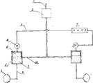
上述的执行机构是当它装在油刹车制动系统时,由控制器的继电器J1引出的电源及控制信号经导线连本装置加设在制动系统的刹车总泵与两后轮分泵之间控制两后轮供油的左、右电磁阀,这两个电磁阀分别连左、右缸筒中的柱塞,两缸筒的一侧有通刹车总泵的进油管,下端为通分泵的出油管;The above-mentioned executive mechanism is when it is installed in the oil brake braking system, the power supply and control signal drawn by the relay J 1 of the controller are connected to the device through wires and added to the brake master cylinder and the two rear wheel sub-cylinders of the braking system. Control the left and right solenoid valves that supply oil to the two rear wheels. These two solenoid valves are respectively connected to the plungers in the left and right cylinders. One side of the two cylinders has an oil inlet pipe leading to the brake master cylinder, and the lower end is the outlet pipe. pump outlet pipe;
当执行机构装在气刹车制动系统时,由控制器的继电器J1引出的电源及控制信号经导线连本装置加设在制动系统的刹车总泵与两后轮分泵之间控制两后轮供风的左、右三通电磁阀,这两个电磁阀分别一端连刹车总泵的出风管,另一端分别连分泵,第三端分别连到本装置上所设置的储风管中。When the actuator is installed in the air brake braking system, the power supply and control signal drawn from the relay J 1 of the controller are connected to this device through wires and installed between the brake master cylinder and the two rear wheel sub-cylinders of the braking system to control the two brake cylinders. The left and right three-way solenoid valves for air supply to the rear wheels, one end of these two solenoid valves is respectively connected to the air outlet pipe of the brake master cylinder, the other end is respectively connected to the sub-pump, and the third end is respectively connected to the air storage installed on the device. tube.
本发明的优点在于:1、控制器采用加速度传感器及智能化的电子控制,反应灵敏,控制可靠;使汽车在转弯时受力平衡,防止侧滑及倾覆。2、可以根据汽车的不同状况调节控制器的灵敏度档位,如空车、载重车、超高车的灵敏档位不同。3、单片计算机有延时功能,可延时1/4秒,如有车行驶过程中的正常巅簸.瞬间的倾斜不刹车,转弯一般超过给定的延时时间。4、使用本装置在转弯前可免去人为的刹车减速,提高了车速,并节省刹车的燃料减少空气污染。5、本装置自动控制转弯时的单向刹车,不用驾驶员操作,不影响原车的制动系统工作。6、安装方便。The advantages of the present invention are: 1. The controller adopts an acceleration sensor and intelligent electronic control, which is sensitive in response and reliable in control; it can balance the force of the car when turning, and prevent sideslip and overturning. 2. The sensitivity gear of the controller can be adjusted according to the different conditions of the car, such as the sensitive gear of an empty car, a loaded car, and a super high car. 3. The single-chip computer has a delay function, which can delay the time by 1/4 second. For example, when a car is driving, there is a normal bump, an instant tilt without braking, and a turn generally exceeds the given delay time. 4. Using this device can avoid artificial braking deceleration before turning, increase the speed of the vehicle, save fuel for braking and reduce air pollution. 5. This device automatically controls the one-way braking when turning, without the driver's operation, and does not affect the braking system of the original vehicle. 6. Easy to install.
附图说明 Description of drawings
图1是本发明的控制器的方框图;Fig. 1 is the block diagram of controller of the present invention;
图2是本发明的控制器的电路原理图;Fig. 2 is the circuit principle diagram of controller of the present invention;
图3是本发明油刹车执行机构结构示意图;Fig. 3 is a structural schematic diagram of an oil brake actuator of the present invention;
图4是本发明气刹车执行机构结构示意图;Fig. 4 is a structural schematic diagram of the air brake actuator of the present invention;
具体实施方式 Detailed ways
下面结合附图对本发明作进一步说明。The present invention will be further described below in conjunction with accompanying drawing.
由图1可以看到,本装置的控制器的方框图,它是加速度传感器电路经滤波器连中央处理器,该处理器的输出端分别接左路电子开关及右路电子开关,左、右电子开关分别连左、右执行机构;上述的处理器的输出端还分别接数码显示器、预报警电路、调节按键接入上述处理器;稳压电源连控制器的各个部分。As can be seen from Fig. 1, the block diagram of the controller of the device is that the acceleration sensor circuit is connected to the central processing unit through a filter, and the output ends of the processor are respectively connected to the left electronic switch and the right electronic switch, and the left and right electronic switches are The switches are respectively connected to the left and right actuators; the output terminals of the above-mentioned processor are respectively connected to the digital display, the pre-alarm circuit, and the adjustment buttons are connected to the above-mentioned processor; the stabilized power supply is connected to each part of the controller.
由图2可以看到,上述的加速度传感器电路是由加速度传感器U2,及其外围元件电容C12、C13、C15、电阻R4组成.加速度传感器是型号为KX110一50的微电子加工成品,加速度传感器的输出端8脚接由并联的电容C9、C7及电阻R1组或的滤波器,该滤波器的输出端连中央处理器U3输入端13脚;加速度侮感器可测量出汽车的侧向运动的加速度,通过中央处理器的处理变换,为汽车所受的侧向力。It can be seen from Fig. 2 that the above-mentioned acceleration sensor circuit is composed of the acceleration sensor U 2 , and its peripheral components capacitors C 12 , C 13 , C 15 , and resistor R 4. The acceleration sensor is a microelectronic processing model of KX110-50 Finished product, the
上述的中央处理器U3型号为AP 89C205单片计算机,它的输出端8脚9脚分别接左路电子开关及右路电子开关,它的输出端14、15、16、17、18、19脚接数码显示器U5,电阻R7、R16、R18、R20-23为数码显示器的外围电路,计算机输出端11脚接预报警电路,调节按键K1、K2接入该计算机的6、7脚。上述两个按键可以人工调节控制器的灵敏度,本控制器的灵敏度分为0一一9档,单片计算机接收按键K1、K2的输入并控制数码显示器显示昕选灵敏度的档位。电容C2、C4、C6、C8、C11、C14、电阻R5、R10、晶体谐振器Y1及按键K3是单片计算机的外围电路。其中Y1、C4、C5组成主振电路,为单片计算机提供时钟信号,C2、R6、K3组成单片计算机的复位电路,K3为人工复位键。The above-mentioned central processing unit U 3 model is AP 89C205 single-chip computer, and its
上述的左路电子开关及右路电子开关是对称的,其左路电子开关是电阻R12连三极管Q3的基极。三极管Q3的集电极经电阻R3连三极管Q2的基极,该管的集电极连三极管Q1的基极,Q1的发射极经J1连左执行机构;其右路电子开关是电阻R11,连三极管Q6的基极,三极管Q6的集电极经电阻R14连三极管Q7的基极,该管的集电极连三极管Q8的基极,Q8的发射极经J1连右执行机构;The above-mentioned left electronic switch and the right electronic switch are symmetrical, and the left electronic switch is a resistor R12 connected to the base of the transistor Q3 . The collector of transistor Q3 is connected to the base of transistor Q2 through resistor R3 , the collector of this tube is connected to the base of transistor Q1 , and the emitter of Q1 is connected to the left actuator through J1 ; the right electronic switch is Resistor R 11 is connected to the base of transistor Q 6 , the collector of transistor Q 6 is connected to the base of transistor Q 7 through resistor R 14 , the collector of this tube is connected to the base of transistor Q 8 , and the emitter of Q 8 is connected to the base of transistor Q 8 through J 1 with the right actuator;
三极管Q3、Q6是电压变换器,Q2、Q1及Q7、Q8组成电子开关推动执行机构工作。二极管D1、D2对电子开关起保护作用,发光二极管D3、D4对左,右执行动作起指示作用。Transistors Q 3 and Q 6 are voltage converters, and Q 2 , Q 1 and Q 7 and Q 8 form an electronic switch to push the actuator to work. Diodes D 1 and D 2 protect the electronic switch, and light-emitting diodes D 3 and D 4 indicate left and right actions.
上述的预报警电路是由单片计算机的输出端11脚连电阻R13,该电阻连三极管Q9的基极,该三极管集电极连蜂鸣器SP1,该三极管的发射极连电源。The above-mentioned pre-alarm circuit is connected by the output terminal 11 of the single-chip computer to the resistor R 13 , the resistor is connected to the base of the triode Q 9 , the collector of the triode is connected to the buzzer SP 1 , and the emitter of the triode is connected to the power supply.
稳压电源是型号为7805的三端稳压器U1,其1脚接车的电源,3脚输出5V电压,2脚接地;其作用是将车用的12V或24V电瓶电压变换为控制器需要的5V直流稳压电源。The regulated power supply is a three-terminal voltage regulator U 1 of
由图3可以看到,装在油刹车制动系统的执行机构,由控制器的J1引出的电源及控制信号,经导线3连本装置加设在制动系统的刹车总泵2与两后轮分泵7之间控制两后轮供油的左、右电磁阀4,这两个电磁阀分别连左、右缸筒6中的柱塞5,两缸筒的一侧有通刹车总泵的进油管10,下端为通分泵的出油管8;当控制器发出控制信号时,左或右电磁阀4工作柱塞5向下运动,把进油管10封住,从出油管8出油9,使一侧分泵油压增大而单向刹车,矫正倾斜后,控制信号中断,柱塞回位,由进油管10回油,1为总进油管。It can be seen from Fig. 3 that the executive mechanism installed in the oil brake braking system, the power supply and control signal drawn from the J1 of the controller, are connected to the
由图4可以看到装在气刹车制动系统的执行机构,由控制器的J1引出的电源及控制信号经导线17连本装置加设在制动系统的刹车总泵11与两后轮分泵15之间控制两后轮供风的左、右三通电磁阀14,这两个电磁阀分别一端连刹车总泵的出风管16,另一端连分泵15,第三端分别连由本装置所加的由储风管12引出的风管13。当控制器发出控制信号时,左或右电磁阀14工作,封住出风管16,使风管13与分泵导通,一侧分泵由储风管12进风而单向刹车;矫正倾斜后,控制信号中断,电磁阀回位,由分泵15经出风管16回风。It can be seen from Fig. 4 that the executive mechanism installed in the air brake braking system, the power supply and control signal drawn by J1 of the controller are connected to the brake master cylinder 11 and the two rear wheels of the device through the wire 17. The left and right three-
加速度传感器在安装时将主感应轴垂直于汽车的前进方向,在汽车行进中受到侧向力时,加速度传感器有信号输出,经过滤波送入单片计算机中,该计算机对其信号进行A/D变换,并与设置的灵敏度档位进行比较,以决定是否报警或控制左、右电子开关推动执行机构。当车向右转弯速度快时,车向左倾斜,加速度传感器输出一信号,该送入计算机的信号达到灵敏度档位的给定值时,其输出端8脚输出控制信号,使左电子开关工作,推动左执行机构单向刹车。同时蜂鸣器报警。When the acceleration sensor is installed, the main induction axis is perpendicular to the forward direction of the car. When the car is subjected to a lateral force, the acceleration sensor has a signal output, which is filtered and sent to the single-chip computer. The computer performs A/D on its signal. Transform and compare with the set sensitivity gear to decide whether to alarm or control the left and right electronic switches to push the actuator. When the car turns to the right and the speed is fast, the car tilts to the left, the acceleration sensor outputs a signal, and when the signal sent to the computer reaches the given value of the sensitivity gear, the
Claims (4)
Priority Applications (2)
| Application Number | Priority Date | Filing Date | Title |
|---|---|---|---|
| CNB011215208A CN100545012C (en) | 2001-06-08 | 2001-06-08 | Electronically controlled automatic anti-overturn device for automobiles |
| PCT/CN2001/001588 WO2003026939A1 (en) | 2001-06-08 | 2001-11-29 | An anti-skid apparatus for a vehicle |
Applications Claiming Priority (1)
| Application Number | Priority Date | Filing Date | Title |
|---|---|---|---|
| CNB011215208A CN100545012C (en) | 2001-06-08 | 2001-06-08 | Electronically controlled automatic anti-overturn device for automobiles |
Publications (2)
| Publication Number | Publication Date |
|---|---|
| CN1390727A CN1390727A (en) | 2003-01-15 |
| CN100545012C true CN100545012C (en) | 2009-09-30 |
Family
ID=4664500
Family Applications (1)
| Application Number | Title | Priority Date | Filing Date |
|---|---|---|---|
| CNB011215208A Expired - Fee Related CN100545012C (en) | 2001-06-08 | 2001-06-08 | Electronically controlled automatic anti-overturn device for automobiles |
Country Status (2)
| Country | Link |
|---|---|
| CN (1) | CN100545012C (en) |
| WO (1) | WO2003026939A1 (en) |
Families Citing this family (7)
| Publication number | Priority date | Publication date | Assignee | Title |
|---|---|---|---|---|
| DE202004009307U1 (en) * | 2004-06-11 | 2004-12-02 | Gaslock Gmbh | Device for indicating the gear engaged |
| US8935048B2 (en) | 2011-03-24 | 2015-01-13 | Yuliang Sun | Multi-function vehicle-rollover judgment system and automatic anti-rollover device |
| CN102092374B (en) * | 2011-03-24 | 2013-08-07 | 孙玉亮 | Multi-functional vehicle rollover decision system and automatic rollover-preventing device |
| CN102628687A (en) * | 2012-04-28 | 2012-08-08 | 浙江海洋学院 | Ship horizontal attitude indicator |
| CN102991492B (en) * | 2012-12-10 | 2015-08-12 | 荣成华泰汽车有限公司 | Vehicle is brake system and method initiatively |
| CN109704236B (en) * | 2018-12-17 | 2020-07-17 | 集美大学诚毅学院 | Forklift with anti-toppling function |
| CN110539734B (en) * | 2019-09-18 | 2020-07-03 | 厦门兴联智控科技有限公司 | Unmanned small tool vehicle and automatic parking method thereof |
Family Cites Families (5)
| Publication number | Priority date | Publication date | Assignee | Title |
|---|---|---|---|---|
| US4852950A (en) * | 1987-09-16 | 1989-08-01 | Toyota Jidosha Kabushiki Kaisha | Vehicle braking system capable of preventing rock-back motion of driver/passenger upon vehicle stopping |
| JP2668751B2 (en) * | 1991-11-30 | 1997-10-27 | 三菱自動車工業株式会社 | Rear wheel braking force control device |
| GB9318502D0 (en) * | 1993-09-07 | 1993-10-20 | Lucas Ind Plc | Apparatus for and method of resonance control in a brake intervention traction control system |
| JP3708989B2 (en) * | 1995-05-16 | 2005-10-19 | 三菱自動車工業株式会社 | Vehicle turning control device |
| JP3812017B2 (en) * | 1996-10-30 | 2006-08-23 | アイシン精機株式会社 | Vehicle motion control device |
-
2001
- 2001-06-08 CN CNB011215208A patent/CN100545012C/en not_active Expired - Fee Related
- 2001-11-29 WO PCT/CN2001/001588 patent/WO2003026939A1/en not_active Ceased
Also Published As
| Publication number | Publication date |
|---|---|
| WO2003026939A1 (en) | 2003-04-03 |
| CN1390727A (en) | 2003-01-15 |
Similar Documents
| Publication | Publication Date | Title |
|---|---|---|
| US4854409A (en) | Lift axle control system | |
| US5068792A (en) | Method and an arrangement for adjusting a height control system of a vehicle | |
| JPS62292556A (en) | Brake system | |
| CN106089459A (en) | A kind of method of electric-control motor gas pedal characteristic self study | |
| CN107757580A (en) | A kind of commercial car automatic parking brake control system | |
| WO2003026939A1 (en) | An anti-skid apparatus for a vehicle | |
| US6212451B1 (en) | Pneumatic suspension leveling system for vehicles | |
| CN107000708B (en) | The vehicle fitting of power-saving running with signal input device | |
| JP2614268B2 (en) | Skid prevention control device for vehicle | |
| CN108556830A (en) | A kind of controlled pneumatic brake system of car and its control method | |
| CN109070868A (en) | Brake device, brake control method, and motor lock abnormality judging method | |
| JPH0367769A (en) | Anti-skid control device | |
| CN114087099A (en) | Fuel supply system and method for cargo vehicle | |
| JPH0324417Y2 (en) | ||
| US5025379A (en) | System and method for automatically controlling vehicle speed to desired cruise speed using microcomputer | |
| CN204821537U (en) | Braking main valve | |
| CN104401390B (en) | The ratio control system of contactless limiting steering and proportional controlling means | |
| CN218198176U (en) | A pure electric muck truck operation mode control system | |
| JPH0538138A (en) | Power supply of on-vehicle electronic controls | |
| JPH01269656A (en) | Trouble judging device for vehicle and antiskid controller using said device | |
| CN116215652A (en) | Failure control method and device for hydraulic steering gear, vehicle and storage medium | |
| CN2477482Y (en) | Automatic overturn-preventing device for automobile | |
| CN219192167U (en) | Automatic braking system of mining explosion-proof diesel engine | |
| CN203126767U (en) | Driver safety belt prompt compulsory execution device | |
| JPS61238554A (en) | Brake hydraulic pressure control device |
Legal Events
| Date | Code | Title | Description |
|---|---|---|---|
| C06 | Publication | ||
| PB01 | Publication | ||
| C10 | Entry into substantive examination | ||
| SE01 | Entry into force of request for substantive examination | ||
| C14 | Grant of patent or utility model | ||
| GR01 | Patent grant | ||
| CF01 | Termination of patent right due to non-payment of annual fee | ||
| CF01 | Termination of patent right due to non-payment of annual fee |
Granted publication date: 20090930 Termination date: 20160608 |