CN100575503C - The Sealing Method of Blast Furnace Stave Joints and the Sealing Parts Used - Google Patents
The Sealing Method of Blast Furnace Stave Joints and the Sealing Parts Used Download PDFInfo
- Publication number
- CN100575503C CN100575503C CN200510028261A CN200510028261A CN100575503C CN 100575503 C CN100575503 C CN 100575503C CN 200510028261 A CN200510028261 A CN 200510028261A CN 200510028261 A CN200510028261 A CN 200510028261A CN 100575503 C CN100575503 C CN 100575503C
- Authority
- CN
- China
- Prior art keywords
- stave
- blast furnace
- sealing
- steel
- seal
- Prior art date
- Legal status (The legal status is an assumption and is not a legal conclusion. Google has not performed a legal analysis and makes no representation as to the accuracy of the status listed.)
- Expired - Fee Related
Links
Images


Landscapes
- Furnace Housings, Linings, Walls, And Ceilings (AREA)
- Blast Furnaces (AREA)
Abstract
一种高炉冷却璧接缝的密封方法及其所用密封件,方法包括如下步骤:首先提供一种具有一定柔性的密封件,其宽度和长度与高炉冷却璧接缝的尺寸相适应;通过不锈钢钢丝将两根钢条具有一定间隔地绑扎在上述密封件上,该钢条的长度等同于密封件长度:将冷却壁与冷却壁对接,利用焊条,将密封件上的两根钢条与冷却壁本体通过点焊连接;将焊接在新冷却壁上的密封件随同新冷却壁一起,由施工人员通过炉外操作,安装到高炉破损冷却壁更换部位;待新冷却壁全部安装完毕,通过遥控喷涂方式对炉内侧的接缝加以充填密实。采用密封件事先安装在冷却壁上的方式,解决了炉外对冷却壁接缝进行密封的难题。

A method for sealing a joint of a blast furnace cooling wall and a sealing member used therefor, the method comprising the following steps: firstly, a sealing member with certain flexibility is provided, the width and length of which are adapted to the size of the joint of a blast furnace cooling wall; Bind two steel bars with a certain interval on the above-mentioned seal, the length of the steel bar is equal to the length of the seal: connect the stave to the stave, use welding rods, connect the two steel bars on the seal to the stave The main body is connected by spot welding; the seals welded on the new cooling stave are installed together with the new cooling stave by the construction personnel through the operation outside the furnace, and installed on the replacement part of the damaged cooling stave of the blast furnace; The method is to fill and compact the seams inside the furnace. The seal is installed on the stave in advance, which solves the problem of sealing the joint of the stave outside the furnace.
Description
技术领域 technical field
本发明属高炉冷却壁安装技术领域,更具体的是涉及一种高炉冷却壁接缝的密封方法及其所用密封件。The invention belongs to the technical field of installation of blast furnace staves, and more specifically relates to a method for sealing joints of blast furnace staves and a sealing member used therein.
背景技术 Background technique
通常,冷却壁式高炉在冷却壁安装后,由于其冷却壁安装工艺的需要,一般在冷却壁之间都存在间隙,如宝钢三高炉基建冷却壁间接缝宽度为50mm。同时冷却壁与炉壳间也存在空隙,需压入高导热性耐火料以保证冷却壁良好的冷却效果,并防止高炉煤气窜至炉壳,引起铁壳温度升高。为保证耐火料压入作业的正常进行,对冷却壁间的接缝必须加以封堵,否则在冷却壁背部压入耐火料将难以实施。Usually, after stave installation of stave blast furnace, there are gaps between staves due to the requirement of stave installation process, for example, the gap between staves of Baosteel No. At the same time, there is also a gap between the stave and the furnace shell, and high thermal conductivity refractory materials need to be pressed in to ensure a good cooling effect of the stave and prevent the blast furnace gas from flowing into the furnace shell, causing the temperature of the iron shell to rise. In order to ensure the normal operation of pressing the refractory material, the joints between the staves must be sealed, otherwise it will be difficult to press the refractory material into the back of the stave.
现有的高炉基建时常用的密封方法是:在每块冷却壁安装结束后,施工人员在炉内利用扁铁和圆钢把冷却壁间接缝(靠炉壳处)压住,然后再将扁铁和圆钢焊接在高炉炉壳上。待全部冷却壁安装结束,还是由施工作业人员在高炉内用不定形耐火材料手工把缝隙填充密实。The commonly used sealing method during the existing blast furnace infrastructure construction is: after the installation of each stave, the construction personnel use flat iron and round steel to press the joint between the staves (close to the furnace shell) in the furnace, and then seal the stave Iron and round steel are welded to the blast furnace shell. After the installation of all staves is completed, the construction workers will manually fill the gaps with amorphous refractory materials in the blast furnace.
基建的冷却壁接缝密封作业都是在高炉内进行的,一旦高炉利用定修时间(常规休风时间24小时,实施破损冷却壁热态更换则控制在100小时以内)实施破损冷却壁热态更换,由于炉内温度一般在200℃以上,且煤气浓度在1000ppm以上,存在很大的安全隐患,根本没有时间也没有条件在炉内搭设施工平台让施工人员进入炉内作业,因此常规基建所采用的技术无法实施。同时,由于冷却壁是局部更换,周围还留有旧的冷却壁,如果事先在新冷却壁上焊接扁钢(钢和铸铁焊接还有很大的难度),则会影响新冷却壁的就位。The seam sealing of staves in the infrastructure is carried out in the blast furnace. Once the blast furnace takes advantage of the scheduled repair time (the conventional wind-off time is 24 hours, and the replacement of damaged staves in thermal state is controlled within 100 hours), the thermal state of damaged staves will be implemented. Replacement, because the temperature in the furnace is generally above 200°C, and the gas concentration is above 1000ppm, there is a great potential safety hazard, and there is no time or condition to build a construction platform in the furnace for construction personnel to work in the furnace, so the conventional infrastructure The technology employed cannot be implemented. At the same time, since the stave is partially replaced, and there are still old staves around, if flat steel is welded on the new stave in advance (the welding of steel and cast iron is still very difficult), it will affect the placement of the new stave .
因此,迫切需要有一种装置和方法能够解决上述问题,即:在不影响冷却壁安装的前提下,施工人员不需进入高炉内即可完成冷却壁间接缝的密封,从而保证冷却壁背部空隙压入,防止高炉煤气窜至炉壳。Therefore, there is an urgent need for a device and method that can solve the above problems, that is, on the premise of not affecting the installation of staves, construction personnel can complete the sealing of the joints between staves without entering the blast furnace, so as to ensure the back gap pressure of staves. to prevent blast furnace gas from entering the furnace shell.
发明内容 Contents of the invention
本发明的目的在于提供一种密封方法及其所用密封件:在施工人员不进到炉内的情况下,能有效地密封相邻冷却壁间的接缝,防止冷却壁背部压入的耐火料冲出并造成压浆作业失败;同时能减少喷涂深度,缩短喷涂时间,并保证喷涂料快速填充和结构密实。The object of the present invention is to provide a sealing method and the sealing parts used therein: without the construction personnel entering the furnace, the seams between adjacent staves can be effectively sealed, and the refractory materials pressed into the back of the staves can be prevented. It will rush out and cause the grouting operation to fail; at the same time, it can reduce the spraying depth, shorten the spraying time, and ensure the rapid filling and compact structure of the sprayed paint.
为实现上述目的,本发明提供一种高炉冷却壁接缝的密封方法,该密封方法基本思路是:设计一种密封件,此密封件可事先安装在每块新冷却壁上,然后随新冷却壁一起在高炉内就位,新设计的密封件能有效地密封相邻冷却壁间的接缝。该方法包括如下步骤:In order to achieve the above object, the present invention provides a sealing method for the seam of a blast furnace stave. The basic idea of the sealing method is to design a seal, which can be installed on each new stave in advance, and then cooled with the new one. The walls are seated together in the blast furnace and the newly designed seal effectively seals the joints between adjacent staves. The method comprises the steps of:
(1)首先提供一种具有一定柔性的密封件,其宽度和长度与高炉冷却壁接缝的尺寸相适应;(1) Firstly, a kind of flexible sealing member is provided, whose width and length are compatible with the size of the blast furnace stave joint;
(2)通过不锈钢钢丝将两根钢条具有一定间隔地绑扎在上述密封件上,该钢条的长度等同于密封件长度;(2) Bind two steel bars with a certain interval on the above-mentioned seal by stainless steel wire, and the length of the steel bar is equal to the length of the seal;
(3)将冷却壁与冷却壁对接,利用焊条,将密封件上的两根钢条与冷却壁本体通过点焊连接;(3) Stave is docked with stave, and two steel bars on the sealing member are connected with stave body by spot welding by welding rod;
(4)将焊接在新冷却壁上的密封件随同新冷却壁一起,由施工人员通过炉外操作,安装到高炉破损冷却壁更换部位;(4) Install the seal welded on the new stave together with the new stave to the replacement part of the damaged stave of the blast furnace by the construction personnel through operation outside the furnace;
(5)待新冷却壁全部安装完毕,通过遥控喷涂方式对炉内侧的接缝加以充填密实。(5) After all the new staves are installed, the joints inside the furnace are filled and compacted by remote control spraying.
根据本发明的一个技术方案,上述步骤(1)还包括如下步骤:a)在直径约为Φ50mm的芯棒外缠绕一层陶瓷纤维布XF-B;b)在陶瓷纤维布外包扎一层耐热不锈钢钢丝网;c)将芯棒抽除,同时用耐热不锈钢钢丝将陶瓷纤维布和不锈钢钢丝网绑在一起。According to a technical solution of the present invention, the above step (1) also includes the following steps: a) wrapping a layer of ceramic fiber cloth XF-B outside the mandrel with a diameter of about Φ50mm; b) wrapping a layer of ceramic fiber cloth XF-B outside the ceramic fiber cloth Heat stainless steel wire mesh; c) extract the mandrel, and tie the ceramic fiber cloth and stainless steel wire mesh together with heat-resistant stainless steel wire.
根据本发明的另一个技术方案,上述步骤(2)中的两根钢条采用Φ8mm的冷拔钢筋,该两根钢条的径向夹角约为30°。According to another technical solution of the present invention, the two steel bars in the above step (2) adopt Φ8mm cold-drawn steel bars, and the radial angle between the two steel bars is about 30°.
根据本发明的又一个技术方案,在上述步骤(3)中,每根钢条与冷却壁采用分段焊接方式,焊点间距200mm,焊缝长50mm。According to yet another technical solution of the present invention, in the above step (3), each steel bar and the stave are welded in sections, with a welding point spacing of 200 mm and a weld seam length of 50 mm.
为实现上述目的,本发明还提供一种密封件,该密封件为中空圆柱形,具有内外两层式结构,内层为陶瓷纤维布,外层为不锈钢钢丝网.In order to achieve the above purpose, the present invention also provides a sealing member, which is hollow cylindrical and has an inner and outer two-layer structure, the inner layer is ceramic fiber cloth, and the outer layer is stainless steel wire mesh.
优选的,该密封件中的陶瓷纤维布为XF-B材质;不锈钢钢丝网为1Cr18Ni9Ti。Preferably, the ceramic fiber cloth in the sealing member is made of XF-B; the stainless steel wire mesh is made of 1Cr18Ni9Ti.
本发明的具有如下优点:密封件两层设计,不锈钢钢丝网挡住喷涂料,陶瓷纤维布挡住压入料,同时又带有一定的柔性,便于冷却壁炉内就位。密封件采用焊接方式连接在冷却壁上,相比绑扎方式,具有牢固、不易脱落的特点。The invention has the following advantages: two-layer design of the seal, stainless steel wire mesh to block the spray paint, ceramic fiber cloth to block the pressed material, and at the same time, it has a certain flexibility, which is convenient for cooling the fireplace. The seal is connected to the cooling wall by welding, which is firm and not easy to fall off compared with the binding method.
附图说明 Description of drawings
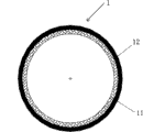
图1为密封件示意图;Figure 1 is a schematic diagram of a seal;
图2为密封件上绑扎钢条示意图;Fig. 2 is a schematic diagram of binding steel bars on the seal;
图3为密封件焊接示意图。Fig. 3 is a schematic diagram of sealing member welding.
具体实施方式 Detailed ways
图1-图3为本发明的优选实施例,为达到本发明的上述目的,本发明的设计构思是:首先,密封件安装在冷却壁上后,能有效的封堵冷却壁间的接缝,故密封件的直径应等同于接逢宽度;其次,由于新更换的冷却壁是通过施工人员炉外操作,使之炉内就位,为保证其顺利安装就位,此密封件不能妨碍新冷却壁的安装,故必须设计成刚中带有一定的柔性;最后,此密封件需同时封堵喷涂料和压入料,炉内喷涂料需粘附在密封件上,而冷却壁背部的压入料则不能穿透密封件。Fig. 1-Fig. 3 is the preferred embodiment of the present invention, in order to achieve the above-mentioned purpose of the present invention, the design idea of the present invention is: firstly, after the sealing member is installed on the stave, the seam between the staves can be effectively blocked , so the diameter of the seal should be equal to the width of the joint; secondly, since the newly replaced stave is operated by the construction personnel outside the furnace to make it in place in the furnace, in order to ensure its smooth installation, the seal cannot hinder the new The installation of the stave must be designed with a certain degree of flexibility in the rigidity; finally, the seal must block the sprayed material and the press-in material at the same time, the sprayed material in the furnace must adhere to the seal, and the back of the stave Press-fit materials cannot penetrate the seal.
参见图1,该密封件1为中空圆条结构件,直径Φ50mm,长度550~1000mm。内层11结构为进口陶瓷纤维布XF-B,外层12结构为耐热不锈钢钢丝网(304#,1Cr18Ni9Ti),同时用耐热不锈钢钢丝将陶瓷纤维布和不锈钢钢丝缝绑在一起。具体制作步骤为:①在直径Φ50mm的芯棒外缠绕一层进口陶瓷纤维布XF-B;②在进口陶瓷纤维布外包扎一层耐热不锈钢钢丝网;③将芯棒抽除,同时用耐热不锈钢钢丝将陶瓷纤维布和不锈钢钢丝缝绑在一起。Referring to Fig. 1, the sealing
对于密封件1的安装,也曾考虑过把密封件用钢丝直接绑扎在冷却壁2上,但通过冷却壁安装模拟试验,发现密封件在冷却壁安装过程中易脱落,因此此方法不可行,最后决定采用焊接形式把密封件安装在冷却壁上。但需要先绑扎钢条3,为保证密封件安装牢固,预先在每根密封条上用耐热不锈钢钢丝(Φ0.5mm)绑扎两根钢条,如图2所示,考虑到焊接工艺需要,钢条采用Φ8mm的冷拔钢筋,两根钢条夹角约30°,绑扎的钢条长度等同于密封件长度。For the installation of the
在绑轧钢条3之后,开始焊接步骤,密封件1安装采用焊接形式,通过绑扎在密封件上的两根钢条和冷却壁铸铁本体点焊连接。由于冷却壁2本体材质为铸铁,故焊条也采用铸铁焊条。另冷却壁与冷却壁对接安装,故每块冷却壁三个面焊接密封件。After the
上述焊接方法为手工电弧焊。焊接极性:直流反接。焊条牌号:铸308,Φ2.5mm,焊前150℃烘烤1小时,焊条烘干后,应放在120~150℃的保温箱内,随用随取。焊接电流:65~90A。每根钢条3与冷却壁2采用分段焊接方式,焊点间距200mm,焊缝长50mm。The above welding method is manual arc welding. Welding polarity: DC reversed. Electrode grade: cast 308, Φ2.5mm, bake at 150°C for 1 hour before welding, and put the electrode in an incubator at 120-150°C after drying, and take it out whenever you need it. Welding current: 65~90A. Each
在焊接之后,要对焊接质量进行检查,即对每个焊点进行着色检查,确保焊接无缺陷。然后,开始耐材充填的工序:焊接在新冷却壁上的密封件随新冷却壁一起,由施工人员通过炉外操作,安装到高炉破损冷却壁更换部位。待新冷却壁全部安装完毕,通过遥控喷涂方式对炉内侧约250mm深的接缝加以充填密实。After welding, the welding quality should be inspected, that is, color inspection is carried out for each solder joint to ensure that there are no defects in the welding. Then, start the process of refractory material filling: the seal welded on the new stave is installed together with the new stave by the construction personnel outside the furnace to replace the damaged stave of the blast furnace. After all the new staves are installed, the joints about 250mm deep inside the furnace are filled and compacted by remote control spraying.
利用炉顶50T行车及三根钢链将喷注机器进入炉内,并使其位于高炉中心线上。压缩空气水雾吹扫,要求喷注表面无浮灰及松动的耐材、料矿。喷涂量每小时3.5吨。喷涂走行控制要求连续稳定。水平:喷补料束以水平缝圆周中心线为基准,需控制在±200mm以内。垂直:喷补料束以垂直缝中心线为基准,需控制在±200mm以内。喷完一条缝后,通过操纵控制系统对准另一条缝。Use the 50T crane on the top of the furnace and three steel chains to enter the injection machine into the furnace and make it located on the center line of the blast furnace. Compressed air water mist blowing requires injection of refractory materials and ores without floating ash and loosening on the surface. The spraying volume is 3.5 tons per hour. Spraying travel control requires continuous stability. Level: The gunning material bundle is based on the centerline of the horizontal seam circle and must be controlled within ±200mm. Vertical: The gunning material beam is based on the centerline of the vertical seam and needs to be controlled within ±200mm. After spraying one seam, aim at another seam by manipulating the control system.
采用密封件事先安装在冷却壁上的方式,解决了不进人对冷却壁接缝进行密封的难题。通过在冷却壁上安装密封件,将冷却壁间接缝喷涂深度从700mm降至250mm,减少喷涂料43吨,缩短喷涂时间约12小时,且由于喷涂深度减少,喷涂密实度增强,起到了有效的密封效果;同时由于在冷却壁上加装了密封件,冷却壁背部压入料也有了双层密封保障,压入料无炉内冒浆现象。本发明自实施以来,效果明显,达到冷却壁间接缝密封要求。The seal is installed on the cooling wall in advance, which solves the problem of sealing the joints of the cooling wall without people entering. By installing seals on the cooling wall, the spraying depth of the gap between the cooling walls is reduced from 700mm to 250mm, 43 tons of spraying materials are reduced, and the spraying time is shortened by about 12 hours. Due to the reduced spraying depth, the spraying density is enhanced, which plays an effective role Sealing effect; at the same time, due to the addition of seals on the stave, the press-in material at the back of the stave has double-layer sealing protection, and the press-in material has no slurry phenomenon in the furnace. Since the implementation of the invention, the effect is obvious, and the joint sealing requirement between staves is met.
Claims (3)
Priority Applications (1)
| Application Number | Priority Date | Filing Date | Title |
|---|---|---|---|
| CN200510028261A CN100575503C (en) | 2005-07-28 | 2005-07-28 | The Sealing Method of Blast Furnace Stave Joints and the Sealing Parts Used |
Applications Claiming Priority (1)
| Application Number | Priority Date | Filing Date | Title |
|---|---|---|---|
| CN200510028261A CN100575503C (en) | 2005-07-28 | 2005-07-28 | The Sealing Method of Blast Furnace Stave Joints and the Sealing Parts Used |
Publications (2)
| Publication Number | Publication Date |
|---|---|
| CN1904081A CN1904081A (en) | 2007-01-31 |
| CN100575503C true CN100575503C (en) | 2009-12-30 |
Family
ID=37673444
Family Applications (1)
| Application Number | Title | Priority Date | Filing Date |
|---|---|---|---|
| CN200510028261A Expired - Fee Related CN100575503C (en) | 2005-07-28 | 2005-07-28 | The Sealing Method of Blast Furnace Stave Joints and the Sealing Parts Used |
Country Status (1)
| Country | Link |
|---|---|
| CN (1) | CN100575503C (en) |
Families Citing this family (3)
| Publication number | Priority date | Publication date | Assignee | Title |
|---|---|---|---|---|
| CN105368998B (en) * | 2014-08-27 | 2017-08-25 | 宝山钢铁股份有限公司 | A kind of cooling wall dilatation joint ramming method |
| CN104789723B (en) * | 2015-04-14 | 2016-11-23 | 江阴兴澄特种钢铁有限公司 | A kind of blast furnace structure and grouting and lining-making method thereof |
| CN105318842B (en) * | 2015-11-17 | 2018-05-25 | 大连大学 | Pressure pipeline weld seam breakage monitoring sensing system |
Citations (2)
| Publication number | Priority date | Publication date | Assignee | Title |
|---|---|---|---|---|
| JPS602878A (en) | 1983-06-20 | 1985-01-09 | 新日本製鐵株式会社 | Water-cooling type precast panel |
| CN1049922C (en) * | 1996-03-30 | 2000-03-01 | 安阳钢铁集团有限责任公司 | Method for additionally cooling blast furnace bottom water |
-
2005
- 2005-07-28 CN CN200510028261A patent/CN100575503C/en not_active Expired - Fee Related
Patent Citations (2)
| Publication number | Priority date | Publication date | Assignee | Title |
|---|---|---|---|---|
| JPS602878A (en) | 1983-06-20 | 1985-01-09 | 新日本製鐵株式会社 | Water-cooling type precast panel |
| CN1049922C (en) * | 1996-03-30 | 2000-03-01 | 安阳钢铁集团有限责任公司 | Method for additionally cooling blast furnace bottom water |
Also Published As
| Publication number | Publication date |
|---|---|
| CN1904081A (en) | 2007-01-31 |
Similar Documents
| Publication | Publication Date | Title |
|---|---|---|
| CN101774063B (en) | Defect repair welding process of stainless steel composite board coating | |
| CN102912051B (en) | Method for exchanging cooling wall of blast furnace taphole online | |
| CN102423826B (en) | Welding process of large connecting tube of vacuum vessel | |
| CN103343592A (en) | Large closed E-shaped thick plate built-up box type column and production method thereof | |
| CN110576245A (en) | Fully automatic argon arc welding method for girth weld of duplex stainless steel pipe | |
| CN107858480A (en) | A kind of converter taphole restorative procedure | |
| CN105420432B (en) | A kind of replacing options of blast furnace cooling stave | |
| CN100575503C (en) | The Sealing Method of Blast Furnace Stave Joints and the Sealing Parts Used | |
| CN103481008B (en) | Deep-hole repair welding technology | |
| CN101829838A (en) | Welding method | |
| CN100493799C (en) | Method of welding the plug in type connection tube and the un-orthogonal crossed connection joint of the cylinder | |
| CN212537891U (en) | Carbon steel flue/chimney lining stainless steel plate structure | |
| CN206163899U (en) | Corrosion resistant lightning rod | |
| CN106350081B (en) | Coke furnace carbonization chamber hot repair heat-insulating method | |
| CN101619373B (en) | Method for plugging outer hole of steel tapping hole of converter | |
| CN105586457B (en) | A Method Applicable to the Damage Repair of Partial Skin Cooling Stave in the Late Stage of Blast Furnace Operation | |
| CN109483103B (en) | Method for treating liner at welding port of steel chimney without entering | |
| CN107326142A (en) | A kind of bottom-blowing of converter shield brick and its building method and smelting process | |
| CN111496357A (en) | Transverse welding method for BB41-BF hot blast furnace shell | |
| CN112680555B (en) | A blast furnace residual iron discharge structure, blast furnace and blast furnace residual iron discharge method | |
| CN110003922A (en) | A kind of method for repairing and mending of peephole brick cup down tube brick | |
| CN204923876U (en) | Heat resisting steel anchor assembly that cement rotary kiln used | |
| CN207686229U (en) | Easy wall plastering roughening device | |
| CN102679056A (en) | Lossless connection method for internal coating tubing | |
| CN203286884U (en) | Kiln tail sealing structure of lime rotary kiln |
Legal Events
| Date | Code | Title | Description |
|---|---|---|---|
| C06 | Publication | ||
| PB01 | Publication | ||
| C10 | Entry into substantive examination | ||
| SE01 | Entry into force of request for substantive examination | ||
| C14 | Grant of patent or utility model | ||
| GR01 | Patent grant | ||
| CF01 | Termination of patent right due to non-payment of annual fee |
Granted publication date: 20091230 Termination date: 20160728 |
|
| CF01 | Termination of patent right due to non-payment of annual fee |