CN100577111C - Method and device for displaying blood flow image using ultrasonic Doppler information - Google Patents
Method and device for displaying blood flow image using ultrasonic Doppler information Download PDFInfo
- Publication number
- CN100577111C CN100577111C CN200710188523A CN200710188523A CN100577111C CN 100577111 C CN100577111 C CN 100577111C CN 200710188523 A CN200710188523 A CN 200710188523A CN 200710188523 A CN200710188523 A CN 200710188523A CN 100577111 C CN100577111 C CN 100577111C
- Authority
- CN
- China
- Prior art keywords
- value
- intensity
- doppler
- signal
- circuit
- Prior art date
- Legal status (The legal status is an assumption and is not a legal conclusion. Google has not performed a legal analysis and makes no representation as to the accuracy of the status listed.)
- Expired - Fee Related
Links
Images



Landscapes
- Ultra Sonic Daignosis Equipment (AREA)
Abstract
本发明涉及超声诊断技术,特别是涉及一种利用超声多普勒信息显示血流图像的方法及装置,其特征是:①按照预定的重复频率向感兴趣方向或感兴趣区域发射超声脉冲,并接收从这些方向或区域内返回的回声信号;②从上述回声信号中提取一系列采样容积的正交复合多普勒差频信号;③计算所述的正交复合多普勒差频信号的延迟自相关强度;④依据所述的延迟自相关强度显示血流图像。在信噪比较低、且不增加发射功率的情况下也能够比较清晰地利用超声多普勒信息显示血流图像。
The present invention relates to ultrasonic diagnostic technology, in particular to a method and device for displaying blood flow images using ultrasonic Doppler information, which is characterized in that: ① transmit ultrasonic pulses to the direction of interest or the area of interest according to a predetermined repetition frequency, and Receiving echo signals returning from these directions or areas; ② extracting a series of quadrature composite Doppler beat signals of a sampling volume from the above echo signals; ③ calculating the delay of the quadrature composite Doppler beat signals Autocorrelation strength; ④ display blood flow images according to the delayed autocorrelation strength. In the case of a low signal-to-noise ratio and without increasing the transmission power, the blood flow image can be clearly displayed by using ultrasonic Doppler information.
Description
技术领域 technical field
本发明涉及超声诊断技术,特别是涉及一种利用超声多普勒信息显示血流图像的方法及装置。The invention relates to ultrasonic diagnosis technology, in particular to a method and device for displaying blood flow images by using ultrasonic Doppler information.
背景技术 Background technique
现有的超声血流成像技术包括两种基本类型:彩色多普勒速度成像技术与彩色多普勒功率成像技术。The existing ultrasonic blood flow imaging techniques include two basic types: color Doppler velocity imaging technique and color Doppler power imaging technique.
彩色多普勒速度成像技术出现已经有20多年的历史。该技术包括获取一个感兴趣区域内或者感兴趣方向上不同位置的多普勒信号,并用这些多普勒信号评估各采样容积的多普勒相位偏移或频率。多普勒相位偏移或频率与各采样容积中血流的速度成正比,而偏移的极性表明血流方向。在多普勒信号功率达到一定阈值后,根据偏移的幅度及其极性信息编码成彩色信号,重叠显示在结构图像上,可以指示血流的有无、速度及方向。Color Doppler velocity imaging technology has a history of more than 20 years. The technique consists of acquiring Doppler signals at different locations within a region of interest or in a direction of interest and using these Doppler signals to estimate the Doppler phase shift or frequency for each sample volume. The Doppler phase shift or frequency is proportional to the velocity of blood flow in each sample volume, while the polarity of the shift indicates the direction of blood flow. After the Doppler signal power reaches a certain threshold, it is encoded into a color signal according to the magnitude of the offset and its polarity information, and is superimposed and displayed on the structural image, which can indicate the presence, speed and direction of blood flow.
该型对低速血流的显示效果欠佳;对血流速度的显示有角度依赖性;不能显示与超声束接近垂直的血流;而且由于血流多普勒信号的平均频率范围与随机噪声信号的平均频率范围互相重叠,因此一般需要设一个足以完全或者接近完全覆盖噪声范围的功率阈值,只有超过这一阈值的多普勒信号才予以显示,以避免噪声可能引起的显著影响。因此,该技术只适用于显示有较高的信噪比的血流多普勒信号。This type has poor display effect on low-velocity blood flow; the display of blood flow velocity has angle dependence; it cannot display blood flow close to the perpendicular to the ultrasound beam; and due to the average frequency range of the blood flow Doppler signal and the random noise signal Therefore, it is generally necessary to set a power threshold sufficient to completely or nearly completely cover the noise range, and only Doppler signals exceeding this threshold are displayed to avoid possible significant effects caused by noise. Therefore, this technique is only applicable to blood flow Doppler signals that exhibit a high signal-to-noise ratio.
彩色超声多普勒功率成像技术出现也已经有10多年的历史。该技术一般不考虑血流速度的大小,只关注所接收的多普勒信号的强度。计算出一个断面或者一条采样线上的各采样容积的多普勒信号的强度,将其编码成不同亮度的彩色进行表示。该型没有角度依赖性,没有混叠现象;可以良好地显示低速血流、以及与超声束接近垂直的血流;由于可以采用平均技术,显示血流的敏感度较高;也无需设置一个完全或者接近完全覆盖噪声范围的功率阈值,也就是说,即使显示噪声,由于其功率较低,颜色暗淡,不会明显影响具有较大功率值的血流多普勒信号的显示。但是同彩色多普勒速度成像技术一样,只有当多普勒信号功率与噪声功率的信噪比超过一定程度时,才能鲜明、准确地显示血流图像。Color ultrasound Doppler power imaging technology has also appeared for more than 10 years. This technology generally does not consider the size of the blood flow velocity, but only pays attention to the intensity of the received Doppler signal. Calculate the Doppler signal intensity of each sampling volume on a section or a sampling line, and encode it into colors of different brightness for representation. This type has no angle dependence and no aliasing phenomenon; it can well display low-velocity blood flow and blood flow close to the perpendicular to the ultrasound beam; because the average technology can be used, the sensitivity of displaying blood flow is high; there is no need to set a complete Or close to the power threshold that completely covers the noise range, that is to say, even if the noise is displayed, because its power is low and the color is dim, it will not obviously affect the display of the blood flow Doppler signal with a large power value. However, just like color Doppler velocity imaging technology, only when the signal-to-noise ratio of Doppler signal power and noise power exceeds a certain level, can blood flow images be clearly and accurately displayed.
然而,在许多实际临床应用中,如经颅探查或较深部组织探查时,所能接收到的血流多普勒信号常常很弱,甚至明显低于噪声功率;此外,作为一般超声检查的原则,希望探查所用的超声强度尽可能小,特别是探查敏感部位,比如眼部、睾丸、头颅等部位时。这些临床情况或临床要求都可能明显降低超声多普勒信号的信噪比,使现有的彩色超声多普勒成像技术不能鲜明、准确地显示血流的分布。However, in many practical clinical applications, such as transcranial exploration or deep tissue exploration, the blood flow Doppler signal that can be received is often very weak, even significantly lower than the noise power; in addition, as a general ultrasound examination principle , it is hoped that the ultrasonic intensity used for exploration should be as small as possible, especially when detecting sensitive parts, such as eyes, testicles, and skulls. These clinical conditions or clinical requirements may significantly reduce the signal-to-noise ratio of ultrasound Doppler signals, so that the existing color ultrasound Doppler imaging technology cannot clearly and accurately display the distribution of blood flow.
发明内容 Contents of the invention
本发明的目的是提供一种在信噪比较低、且不增加发射功率的情况下也能够比较清晰地利用超声多普勒信息显示血流图像的方法及装置。The purpose of the present invention is to provide a method and device that can clearly display blood flow images by using ultrasonic Doppler information without increasing the transmission power while the signal-to-noise ratio is low.
本发明的目的是这样实现的,利用超声多普勒信息显示血流图像的方法,包括步骤:①按照预定的重复频率向感兴趣方向或感兴趣区域发射超声脉冲,并接收从这些方向或区域内返回的回声信号;②从上述回声信号中提取一系列采样容积的正交复合多普勒差频信号;③依据采样容积的正交复合多普勒差频信号进一步获取延迟自相关强度;④依据所述的延迟自相关强度显示血流图像。The object of the present invention is achieved in this way. The method for displaying blood flow images using ultrasonic Doppler information includes the steps: ① sending ultrasonic pulses to directions of interest or regions of interest according to a predetermined repetition frequency, and receiving ultrasonic pulses from these directions or regions. ②Extract a series of quadrature composite Doppler beat signals of the sampling volume from the above echo signals; ③Further obtain the delayed autocorrelation strength according to the quadrature composite Doppler beat signals of the sampling volume; ④ The blood flow image is displayed according to the delayed autocorrelation strength.
所述的依据延迟自相关强度显示血流图像可以是通过依据延迟自相关强度的变化给出彩色信号亮度的变化或灰阶信号亮度的变化。The displaying of the blood flow image according to the intensity of delayed autocorrelation may be based on the change of the intensity of delayed autocorrelation to give the change of the brightness of the color signal or the change of the brightness of the grayscale signal.
所述的步骤③中可以另外包括依据采样容积的正交复合多普勒差频信号进一步获取血流速度或多普勒频率信息。The
所述的依据延迟自相关强度值显示血流图像可以是依据延迟自相关强度与一个预设值进行比较,如果大于或等于预设值,则进一步根据血流速度或多普勒频率信息进行彩色编码。The display of the blood flow image based on the delayed autocorrelation strength value may be based on comparing the delayed autocorrelation strength with a preset value, and if it is greater than or equal to the preset value, further color-coded according to the blood flow velocity or Doppler frequency information coding.
利用超声多普勒信息显示血流图像的装置,它至少包括:超声信号发射与接收装置1、多普勒信号提取单元2、多普勒信号处算器3、显示单元4;其中超声信号发射与接收装置1至少包括换能器101、发射电路102、接收电路103;换能器101与发射电路102、接收电路103分别电连接,发射电路102用于给换能器101提供电驱动,使其以预定的频率向感兴趣方向或感兴趣区域发射超声脉冲信号,接收电路103则接收并放大从这些方向或区域内返回的回声信号;多普勒信号提取单元2从接收电路103回声信号中提取正交复合多普勒差频信号;经过MTI滤波器105滤波后的各采样容积的I、Q正交复合信号进入多普勒信号处算器3进行处理;多普勒信号处算器3包括自相关强度计算电路106,自相关强度计算电路106包括延迟自相关器200、强度转换电路206a、206b,以及求和变换电路207,正交复合多普勒差频信号1分量通过MTI滤波器105a进行滤波,Q分量通过MTI滤波器105b进行滤波后进入自相关强度计算电路106内,首先由延迟自相关器200进行延迟自相关处理,得到正交复合多普勒差频信号的自相关函数的实部A值与虚部B值,其特征是:实部A值和虚部B值分别与强度转换电路206a、206b电连接,强度转换电路206a、206b与求和变换电路207电连接,求和变换电路207的输出作为延迟自相关强度C值送入显示单元4,显示单元4依据延迟自相关强度C值显示血流图像。A device for displaying blood flow images using ultrasonic Doppler information, which at least includes: an ultrasonic signal transmitting and receiving
所述的强度转换电路206a、206b分别是平方运算器。The
所述的强度转换电路206a、206b分别是绝对值运算器。The
所述的多普勒信号处算器3包括自相关强度计算电路106与血流速度计算器107,自相关强度计算电路106中所得到的自相关函数的实部A值与虚部B值同时提供给血流速度计算器107,血流速度计算器107计算出血流速度,和自相关强度计算电路106所得到的延迟自相关强度C值一起提供给显示单元4用于显示血流图像。The Doppler
所述的求和变换电路207是一个加法器。The
所述的求和变换电路207包含一个加法器208和一个开方运算器209,所述的加法器208的两个输入端分别与强度转换电路206a、206b的输出端电连接,加法器208的输出端与开方运算器209的输入端电连接,开方运算器209的输出作为延迟自相关强度C值送入显示单元4。Described
所述的求和变换电路207包含一个加法器208和一个对数运算器210,所述的加法器208的两个输入端分别与强度转换电路206a、206b的输出端电连接,加法器208的输出端与对数运算器210的输入端电连接,对数运算器210的输出作为延迟自相关强度C值送入显示单元4。Described
本发明的效果:由于随机噪声毫无规律,延迟自相关性很差,而普通正交复合血流多普勒信号的带宽较窄,具有良好的延迟自相关性,因此,采用本发明的技术,依据延迟自相关函数的强度值是否达到阈值来确定是否显示彩色(或灰度)血流信号,或者利用延迟自相关函数的强度值进行彩色或灰度特性(如亮度)的编码可以明显降低噪声的影响,提高低信噪比条件下血流显示的清晰度与灵敏度。Effect of the present invention: because random noise is irregular, delay autocorrelation is very poor, and the bandwidth of ordinary orthogonal composite flow Doppler signal is relatively narrow, has good delay autocorrelation, therefore, adopts the technology of the present invention , according to whether the intensity value of the delayed autocorrelation function reaches the threshold to determine whether to display the color (or grayscale) blood flow signal, or use the intensity value of the delayed autocorrelation function to encode color or grayscale characteristics (such as brightness) can be significantly reduced The influence of noise can improve the clarity and sensitivity of blood flow display under the condition of low signal-to-noise ratio.
本发明的另一个显著优点是方法及结构比较简单。由于可以无需进行多普勒信号的功率评估,其结构复杂程度及运算量可以低于现有的普通彩色速度型多普勒成像装置,更加经济。Another significant advantage of the present invention is that the method and structure are relatively simple. Since the power evaluation of the Doppler signal is unnecessary, the structure complexity and calculation amount can be lower than that of the existing common color velocity Doppler imaging device, which is more economical.
更重要的是,利用本发明技术,可以在不影响血流观察的情况下进一步明显降低超声的发射功率。这对于提高重要部位,如眼部、颅脑部位的超声血流检查及监测的安全性也具有重大价值。More importantly, by using the technology of the present invention, the ultrasonic transmission power can be further significantly reduced without affecting the observation of blood flow. This is also of great value for improving the safety of ultrasonic blood flow inspection and monitoring of important parts, such as eyes and brain parts.
附图说明 Description of drawings
以下结合实施例附图详细说明本发明的优选实施例。Preferred embodiments of the present invention will be described in detail below in conjunction with the accompanying drawings of the embodiments.
图1是按照本发明原则构建的一种超声诊断系统的结构框图;Fig. 1 is a structural block diagram of a kind of ultrasonic diagnostic system constructed according to the principle of the present invention;
图2是符合本发明原则的一种自相关强度计算电路的结构框图;Fig. 2 is a structural block diagram of a kind of autocorrelation intensity calculation circuit conforming to the principle of the present invention;
图3是符合本发明原则的一种求和变换电路的结构框图;Fig. 3 is a structural block diagram of a kind of summation conversion circuit conforming to the principles of the present invention;
图4是符合本发明原则的另一种求和变换电路的结构框图;Fig. 4 is the structural block diagram of another kind of summation conversion circuit that accords with the principle of the present invention;
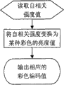
图5是符合本发明原则的一种基本彩色编码方式示意图;Fig. 5 is a schematic diagram of a basic color coding method in accordance with the principles of the present invention;
图6是与图5相应的一种彩色编码器的操作流程图;Fig. 6 is the operation flowchart of a kind of color encoder corresponding to Fig. 5;
图7是符合本发明原则的第二种基本彩色编码方式示意图;Fig. 7 is a schematic diagram of the second basic color coding method in accordance with the principles of the present invention;
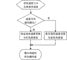
图8是与图7相应的一种彩色编码器的操作流程图;Fig. 8 is the operation flowchart of a kind of color encoder corresponding to Fig. 7;
图9是符合本发明原则的第三种基本彩色编码方式示意图;Fig. 9 is a schematic diagram of a third basic color coding method in accordance with the principles of the present invention;
图10是与图9相应的一种彩色编码器的操作流程图。FIG. 10 is a flowchart of the operation of a color encoder corresponding to FIG. 9 .
图中:1、超声信号发射与接收装置;2、多普勒信号提取单元;3、多普勒信号处算器;4、显示单元;101、换能器;102、发射电路;103、接收电路;104、正交解调器;105a、105b、MTI滤波器;106、自相关强度计算电路;107、血流速度计算器;108、数字扫描转换器;109、彩色编码器;110、显示器;200、延迟自相关器;201a、201b、延迟电路;202a、202b、202c、202d、乘法电路;203、加法器;204、减法器;205a、205b、积分电路;206a、206b、强度转换电路;207、求和变换电路;208、加法器;209、开方运算器;210、对数运算器。In the figure: 1. Ultrasonic signal transmitting and receiving device; 2. Doppler signal extraction unit; 3. Doppler signal processor; 4. Display unit; 101. Transducer; 102. Transmitting circuit; 103. Receiving Circuit; 104, quadrature demodulator; 105a, 105b, MTI filter; 106, autocorrelation strength calculation circuit; 107, blood flow velocity calculator; 108, digital scanning converter; 109, color coder; 110, display ; 200, delay autocorrelator; 201a, 201b, delay circuit; 202a, 202b, 202c, 202d, multiplication circuit; 203, adder; 204, subtractor; 205a, 205b, integration circuit; 206a, 206b, intensity conversion circuit ; 207, a summation conversion circuit; 208, an adder; 209, a square extraction operator; 210, a logarithmic operator.
具体实施方式 Detailed ways
图1是按照本发明原则构建的一种超声诊断系统的结构框图,它是将现有的彩色超声多普勒诊断系统的电路部分替换为本发明的内容后给出的电路框图。除了图中的自相关强度计算电路106及以后的电路外,其电路实现过程可以与现有的没有区别,然而为了完整地说明本发明的实施思想,在下面的说明中作为整体将完整进行说明。Fig. 1 is a structural block diagram of an ultrasonic diagnostic system constructed according to the principle of the present invention, which is a circuit block diagram after replacing the circuit part of the existing color ultrasonic Doppler diagnostic system with the content of the present invention. Except for the autocorrelation
一般情况下,本发明至少包括超声信号发射与接收装置1、多普勒信号提取单元2、多普勒信号处算器3、显示单元4;其中,超声信号发射与接收装置1至少包括:换能器101、发射电路102、接收电路103,换能器101与发射电路102、接收电路103分别电连接。换能器101根据需要可以具有单振元、一维阵列振元、或二维阵列振元。发射电路102用于以预定的频率向感兴趣方向或感兴趣区域发射超声脉冲信号,接收电路103用于接收从这些方向或区域内返回的回声信号。在发射期,发射电路102向换能器101提供电驱动信号,使换能器向机体(已有技术,未显示)发射脉冲型高频超声波。如果换能器101采用阵列式振元,发射电路102中相应可以包含一个发射声束形成器(已有技术,未画出),使提供给各振元的驱动信号之间具有所需要的各种时间延迟,从而可以获得聚焦良好的声束,并且可用于偏转超声束的发射方向。在接收期,从机体反射回来的回声由换能器101转化为回波信号后进入接收电路103进行放大,并被转化为数字信号(在其他实施方式,在接收电路103中可以不具有模数转化模块,不进行模数转化,而直接向后接的模拟式正交解调器提供模拟信号)。如果换能器101包含的是阵列式振元,则接收电路103中相应可以包含一个接收声束形成器(已有技术,未画出),其通过施加不同的时间延迟,使从各振元检测到的回声信号得到最佳聚焦;并且可用以偏转接收方向,定向接收所希望的方向的回声信号。Generally, the present invention at least includes an ultrasonic signal transmitting and receiving
接收电路103输出的回声信号被送入多普勒信号提取单元2,多普勒信号提取单元2至少包括正交解调器104与MTI滤波器105,MTI滤波器105包括MTI滤波器105a和MTI滤波器105b。根据输入的回声信号是否已被转化为数字信号,正交解调器104可以是数字式或模拟式正交相位解调器(均可以采用现有技术)。在这儿回声信号被解调成其正交相位复合信号,包括两个成分:同相分量I与正交分量Q。如果是模拟式正交相位解调器,则在其后还包括一个模数转换器(已有技术,未画出),以将解调所得的模拟式I、Q分量分别转化为数字信号。接着各采样容积的数字式I、Q信号序列被分别送入MTI滤波器105a和MTI滤波器105b进行动目标显示(MTI)滤波,MTI滤波器105相当于一个高通滤波器,用于滤除各采样容积的I、Q信号中所包含的由血管壁、瓣膜、以及其他组织界面等所引起的直流或低频杂波信号。经过MTI滤波器105滤波后的各采样容积的I、Q复信号序列,即其正交复合多普勒差频信号(在本文及其他文献,也经常被简称为多普勒信号或频移信号),进入多普勒信号处算器3。The echo signal output by the receiving
多普勒信号处算器3至少包括自相关强度计算电路106。如图2所示,自相关强度计算电路106包括延迟自相关器200、强度转换电路206a、206b,以及求和变换电路207。上述MTI滤波后的I信号与Q信号进入延迟自相关器200,由两个延迟电路201a、201b,四个乘法电路202a、202b、202c、202d,加法器203、减法器204和两个积分电路205a、205b进行延迟自相关处理,得到自相关函数的实部A值与虚部B值。这种处理过程在现有的自相关强度计算电路中是司空见惯的。而在本发明中一个重要的过程是,对得到的实部A值及虚部B值分别由强度转换电路206a、206b转换成只与实部A值及虚部B值的绝对值大小相关、而与其符号无关的强度值A’、B’,两路强度值输出A’与B’进入求和变换电路207进行求和变换,得到延迟自相关强度C值,然后由后面的显示单元4依据延迟自相关强度C值显示血流图像。The
强度转换电路206a、206b的一种优选实施方式是分别采用一个平方运算器(结构相当于一个乘法器的两个输入端与同一个输入信号相连);通过分别对实部A值及虚部B值进行平方运算,消去其符号,得到只与实部A值及虚部B值的绝对值大小相关的强度值A’、B’。A preferred implementation of the
强度转换电路206a、206b的另一种优选实施方式是分别采用一个绝对值运算器;通过分别对实部A值及虚部B值进行取其绝对值的运算,消去其符号,即得到只与实部A值及虚部B值的绝对值大小相关的强度值A’、B’。Another preferred implementation mode of the
求和变换电路207的一种优选实施方式是一个加法器。其对强度转换电路206a、206b的输出A’、B’进行简单的加法运算,所得的和作为延迟自相关强度C值输出。A preferred embodiment of
求和变换电路207的另一种优选实施方式如图3所示,包括加法器208和开方运算器209,加法器208对强度转换电路206a、206b的输出A’、B’进行加法运算,所得的和送入开方运算器209,所得结果作为延迟自相关强度C值。Another preferred implementation of the
求和变换电路207的另一种优选实施方式如图4所示,包括加法器208和对数运算器210,加法器208对强度转换电路206a、206b的输出A’、B’进行加法运算,所得的和送入对数运算器210,所得的对数值(比如分贝值)作为延迟自相关强度C值。Another preferred implementation of the
通过上述对延迟自相关运算得到的实部A值及虚部B值,经过强度转换电路206a、206b,以及求和变换电路207得到多普勒信号的延迟自相关强度C值作为血流信号的强度指针,比起现有技术的直接对自相关强度计算电路106输入端的I、Q信号进行运算得到多普勒信号功率值P=I2+Q2或其幅度值A=(I2+Q2)0.5作为血流信号进行运算得到多普勒信号功率值P=I2+Q2或其幅度值A=(I2+Q2)0.5作为血流信号的强度指针,可以明显提高信噪比,有利于获取更微弱的血流信号,提高血流显示的灵敏度。Through the above real part A value and imaginary part B value obtained by the delayed autocorrelation calculation, the delayed autocorrelation intensity C value of the Doppler signal is obtained through the
除了自相关强度计算电路106,多普勒信号处算器3还可以优选地包括血流速度计算器107。血流速度计算器107可以采用各种已有技术利用多普勒信号计算血流速度。一种优选方式如图1所示:自相关强度计算电路106中所得到的自相关函数的实部A值与虚部B值同时提供给血流速度计算器107;血流速度计算器107根据A值与B值计算出血流速度(已有技术),与自相关强度计算电路106计算得到的延迟自相关强度C值一起提供给显示单元4。In addition to the autocorrelation
一般情况下,显示单元包括数字扫描转换器108、彩色编码器109、显示器110,其中数字扫描转换器108的作用是将按照超声扫查方式得到的数据重新按照显示器110的扫描方式进行扫描格式转换处理,再送入彩色编码器109编码,然后由显示器110显示血流图像。上述连接顺序中,也可以是彩色编码器109在前,数字扫描转换器108在后,即先由彩色编码器109编码,然后送入数字扫描转换器108,由其按照显示器110的扫描方式进行扫描格式转换处理。In general, the display unit includes a
在本实施例中,提供三种基本的彩色或灰阶编码模式(在只显示血流而不显示解剖结构,而且无需显示血流方向的简单应用中,彩色编码器109可以用一个灰度编码器取代)。In this embodiment, three basic color or gray-scale coding modes are provided (in simple applications where only blood flow is displayed but not anatomical structures, and the direction of blood flow does not need to be displayed, the
第一种编码方式如图5所示,类似普通的彩色功率型多普勒,该编码模式不考虑速度,仅根据延迟自相关强度C值,编码某种颜色(比如红色)或灰阶的亮度:在一定阈值范围内,自相关强度C值越大,彩色或灰阶亮度值越大。The first encoding method is shown in Figure 5, which is similar to ordinary color power Doppler. This encoding mode does not consider the speed, but only encodes the brightness of a certain color (such as red) or gray scale according to the value of the delayed autocorrelation intensity C. : Within a certain threshold range, the greater the autocorrelation intensity C value, the greater the color or grayscale brightness value.
第一种编码方式的具体步骤参考图6,首先读取自相关强度C值,然后可以按以下算式编码红色或其他某种颜色的亮度值:(C-设定的噪声阈值)×64/(设定的检测范围),并将结果规整为0-63的整数,小于0的算作0,超过63的算作63或算作0,最后输出相应的彩色编码值。The specific steps of the first encoding method refer to Figure 6, first read the autocorrelation intensity C value, and then encode the brightness value of red or some other color according to the following formula: (C-set noise threshold) × 64/( The set detection range), and the result is regularized into an integer of 0-63, the value less than 0 is counted as 0, and the value exceeding 63 is counted as 63 or 0, and finally the corresponding color coded value is output.
第二种编码模式如图7所示,类似于现有的彩色方向型功率多普勒编码,即根据速度的方向确定颜色的种类,如流向探头用红色,背离探头用蓝色;根据延迟自相关强度C值确定各颜色的亮度,即在一定阈值范围内,延迟自相关强度C值越大,所编码的颜色越亮。The second encoding mode is shown in Figure 7, which is similar to the existing color directional power Doppler encoding, that is, the type of color is determined according to the direction of the velocity, such as red for the flow direction probe and blue for the deviation probe; The correlation intensity C value determines the brightness of each color, that is, within a certain threshold range, the greater the delayed autocorrelation intensity C value, the brighter the coded color.
第二种编码方式的具体步骤参考图8,首先读取速度方向代码及延迟自相关强度C值,然后判断速度方向是否朝向探头,如是则编码红色亮度值,否则就编码蓝色亮度值,具体可以按以下算式编码红色或蓝色的亮度值:(C-设定的噪声阈值)×64/(设定的检测范围),并将结果规整为0-63的整数,小于0的算作0,超过63的算作63或算作0,最后输出相应的彩色编码值。Refer to Figure 8 for the specific steps of the second encoding method. First, read the velocity direction code and the delayed autocorrelation intensity C value, and then judge whether the velocity direction is facing the probe. If so, encode the red brightness value, otherwise encode the blue brightness value. Specifically The brightness value of red or blue can be encoded according to the following formula: (C-set noise threshold)×64/(set detection range), and the result is regularized into an integer of 0-63, and the value less than 0 is counted as 0 , more than 63 count as 63 or count as 0, and finally output the corresponding color-coded value.
第三种编码模式如图9所示,类似普通的速度型彩色多普勒编码模式,首先将延迟自相关强度C值与一个预设的、用户可以调节的阈值进行比较,如果低于阈值,则不编码彩色信号;如果大于或等于阈值,则进一步根据速度进行彩色编码:根据速度的方向确定颜色的种类,根据速度的大小确定颜色的亮度。The third encoding mode is shown in Figure 9, similar to the common velocity-type color Doppler encoding mode. First, the delayed autocorrelation strength C value is compared with a preset threshold that can be adjusted by the user. If it is lower than the threshold, Then do not encode the color signal; if it is greater than or equal to the threshold, then further perform color coding according to the speed: determine the type of color according to the direction of the speed, and determine the brightness of the color according to the magnitude of the speed.
第三种编码模式的具体步骤参考图10,首先读取速度信息(方向与大小)及延迟自相关强度C值,然后判断延迟自相关强度C是否大于噪声阈值,如果否,彩色亮度值编码为0;如果是,则进一步判断速度方向是否朝向探头,如是则编码红色亮度值,否则就编码蓝色亮度值,具体可以按以下算式编码红色或蓝色的亮度值:血流速度绝对值×64/尼奎斯特速度,并将结果规整为0-63的整数,最后输出相应的彩色编码值。The specific steps of the third encoding mode refer to Figure 10, first read the speed information (direction and size) and the value of the delayed autocorrelation intensity C, and then judge whether the delayed autocorrelation intensity C is greater than the noise threshold, if not, the color brightness value is coded as 0; if yes, further judge whether the velocity direction is towards the probe, if so, encode the red brightness value, otherwise encode the blue brightness value, specifically, the red or blue brightness value can be encoded according to the following formula: absolute value of blood flow velocity × 64 /Nyquist speed, and round the result to an integer from 0-63, and finally output the corresponding color-coded value.
在以上3种基本类型的基础上,还可以有许多变化,比如为了进一步排除组织杂波信号的影响,以上各型均可以设置一个低速(或低频)阈值,只有速度(或多普勒频率)达到或超过该阈值的信号才给与彩色(或灰度)编码。此外,为了突出显示异常高速血流,还可以设一个高速(或高频)阈值,达到或超过该阈值的信号编码一个明显不同的颜色,比如绿色进行突出显示。On the basis of the above three basic types, there can be many changes. For example, in order to further exclude the influence of tissue clutter signals, a low speed (or low frequency) threshold can be set for each of the above types, and only the speed (or Doppler frequency) Signals that meet or exceed this threshold are given color (or grayscale) encoding. In addition, in order to highlight abnormal high-speed blood flow, a high-speed (or high-frequency) threshold can also be set, and signals that reach or exceed this threshold can be coded with an obviously different color, such as green, for highlighting.
最后,编码而成的彩色(或灰阶)信号经数模转换后送入显示器110,或者在送入显示器110后进行数模转换,被显示成二维、三维或M型血流图像。Finally, the coded color (or grayscale) signal is sent to the
以上虽然结合附图描述了本发明的一些具体实施方式,但是本领域的普通技术人员可以在所附权利要求的范围内做出各种变形或修改。Although some specific embodiments of the present invention have been described above in conjunction with the accompanying drawings, those skilled in the art can make various changes or modifications within the scope of the appended claims.
Claims (11)
Priority Applications (1)
| Application Number | Priority Date | Filing Date | Title |
|---|---|---|---|
| CN200710188523A CN100577111C (en) | 2007-12-29 | 2007-12-29 | Method and device for displaying blood flow image using ultrasonic Doppler information |
Applications Claiming Priority (1)
| Application Number | Priority Date | Filing Date | Title |
|---|---|---|---|
| CN200710188523A CN100577111C (en) | 2007-12-29 | 2007-12-29 | Method and device for displaying blood flow image using ultrasonic Doppler information |
Publications (2)
| Publication Number | Publication Date |
|---|---|
| CN101214159A CN101214159A (en) | 2008-07-09 |
| CN100577111C true CN100577111C (en) | 2010-01-06 |
Family
ID=39620708
Family Applications (1)
| Application Number | Title | Priority Date | Filing Date |
|---|---|---|---|
| CN200710188523A Expired - Fee Related CN100577111C (en) | 2007-12-29 | 2007-12-29 | Method and device for displaying blood flow image using ultrasonic Doppler information |
Country Status (1)
| Country | Link |
|---|---|
| CN (1) | CN100577111C (en) |
Families Citing this family (14)
| Publication number | Priority date | Publication date | Assignee | Title |
|---|---|---|---|---|
| CN101828929B (en) * | 2009-03-11 | 2013-06-19 | 中国科学技术大学 | Vector measurement method of Doppler blood flow velocity by utilizing apparent displacement |
| JP6116853B2 (en) * | 2011-11-30 | 2017-04-19 | 東芝メディカルシステムズ株式会社 | Ultrasonic diagnostic apparatus and image processing method |
| CN103142252B (en) * | 2013-03-21 | 2014-11-12 | 飞依诺科技(苏州)有限公司 | Method and system for realizing automatic deflection of spectral Doppler angle |
| CN103876780B (en) * | 2014-03-03 | 2015-07-15 | 天津迈达医学科技股份有限公司 | High-frequency ultrasonic blood flow gray-scale imaging method and high-frequency ultrasonic blood flow gray-scale imaging device |
| EP2989986B1 (en) * | 2014-09-01 | 2019-12-18 | Samsung Medison Co., Ltd. | Ultrasound diagnosis apparatus and method of operating the same |
| CN106491078B (en) * | 2015-09-07 | 2019-06-25 | 南京理工大学 | Remove the method and device of ordered dither noise in blood-stream image |
| CN107753061B (en) * | 2017-11-03 | 2020-08-04 | 飞依诺科技(苏州)有限公司 | Automatic optimization method and system for ultrasound elastography |
| CN108433742A (en) * | 2018-03-29 | 2018-08-24 | 东南大学 | A kind of full depth frequency displacement search type transcranial Doppler detection device of portable modulus and method |
| WO2020018901A1 (en) * | 2018-07-19 | 2020-01-23 | Mayo Foundation For Medical Education And Research | Systems and methods for removing noise-induced bias in ultrasound blood flow imaging |
| US11109841B2 (en) * | 2018-12-06 | 2021-09-07 | General Electric Company | Method and system for simultaneously presenting doppler signals of a multi-gated doppler signal corresponding with different anatomical structures |
| CN112754526A (en) * | 2019-11-05 | 2021-05-07 | 深圳迈瑞生物医疗电子股份有限公司 | Ultrasonic detection method and ultrasonic imaging device for uterine peristalsis |
| CN110811688B (en) * | 2019-12-02 | 2021-10-01 | 云南大学 | Ultrafast ultrasound Doppler blood flow estimation method based on repeated compounding of multi-angle plane waves |
| CN113081108A (en) * | 2021-03-22 | 2021-07-09 | 华中科技大学同济医学院附属协和医院 | Intelligent navigation hemostatic suture needle and control method thereof |
| CN117084716A (en) * | 2022-05-13 | 2023-11-21 | 深圳迈瑞生物医疗电子股份有限公司 | Blood flow spectrum imaging method and ultrasonic imaging device |
Citations (4)
| Publication number | Priority date | Publication date | Assignee | Title |
|---|---|---|---|---|
| US4583409A (en) * | 1983-08-24 | 1986-04-22 | Cgr Ultrasonic | Method for measuring the flow parameters of a fluid and device utilizing the method |
| CN1133166A (en) * | 1995-04-10 | 1996-10-16 | 深圳安科高技术有限公司 | Method and instrument of testing rheoencephalogram by Doppler ultrasonic tech. |
| CN1134808A (en) * | 1995-02-06 | 1996-11-06 | 通用电器横河医疗系统株式会社 | Method of displaying ultrasonic images and apparatus for ultrasonic diagnosis |
| CN101081170A (en) * | 2006-06-02 | 2007-12-05 | 株式会社东芝 | Ultrasonic Doppler diagnostic device and control method for the ultrasonic Doppler diagnostic device |
-
2007
- 2007-12-29 CN CN200710188523A patent/CN100577111C/en not_active Expired - Fee Related
Patent Citations (4)
| Publication number | Priority date | Publication date | Assignee | Title |
|---|---|---|---|---|
| US4583409A (en) * | 1983-08-24 | 1986-04-22 | Cgr Ultrasonic | Method for measuring the flow parameters of a fluid and device utilizing the method |
| CN1134808A (en) * | 1995-02-06 | 1996-11-06 | 通用电器横河医疗系统株式会社 | Method of displaying ultrasonic images and apparatus for ultrasonic diagnosis |
| CN1133166A (en) * | 1995-04-10 | 1996-10-16 | 深圳安科高技术有限公司 | Method and instrument of testing rheoencephalogram by Doppler ultrasonic tech. |
| CN101081170A (en) * | 2006-06-02 | 2007-12-05 | 株式会社东芝 | Ultrasonic Doppler diagnostic device and control method for the ultrasonic Doppler diagnostic device |
Non-Patent Citations (6)
| Title |
|---|
| CDFI原理及其质量控制. 李福星,金宝荣,王昌军.数理医药学杂志,第20卷第3期. 2007 |
| CDFI原理及其质量控制. 李福星,金宝荣,王昌军.数理医药学杂志,第20卷第3期. 2007 * |
| 多普勒彩色血流显像. 洪国瑞.中专物理教学,第5卷第2期. 1997 |
| 多普勒彩色血流显像. 洪国瑞.中专物理教学,第5卷第2期. 1997 * |
| 超声多普勒自相关彩色血流成像原理和数字实现技术研究. 张平,刘影,高兴斌.中国医疗器械杂志,第25卷第1期. 2001 |
| 超声多普勒自相关彩色血流成像原理和数字实现技术研究. 张平,刘影,高兴斌.中国医疗器械杂志,第25卷第1期. 2001 * |
Also Published As
| Publication number | Publication date |
|---|---|
| CN101214159A (en) | 2008-07-09 |
Similar Documents
| Publication | Publication Date | Title |
|---|---|---|
| CN100577111C (en) | Method and device for displaying blood flow image using ultrasonic Doppler information | |
| US6277075B1 (en) | Method and apparatus for visualization of motion in ultrasound flow imaging using continuous data acquisition | |
| EP1515639B1 (en) | Ultrasonic diagnostic microvascular imaging | |
| US6620103B1 (en) | Ultrasonic diagnostic imaging system for low flow rate contrast agents | |
| JP3406106B2 (en) | Ultrasonic image display method and ultrasonic diagnostic apparatus | |
| CN100409814C (en) | Ultrasonic diagnostic device, ultrasonic image data processing method, and image processing device | |
| US8864671B2 (en) | Methods and systems for color flow imaging | |
| US6618493B1 (en) | Method and apparatus for visualization of motion in ultrasound flow imaging using packet data acquisition | |
| EP2322951A2 (en) | Adaptively performing clutter filtering in an ultrasound system | |
| WO2011126729A2 (en) | Methods and apparatus for ultrasound imaging | |
| EP2691026A2 (en) | Methods and apparatus for ultrasound imaging | |
| CN101170947A (en) | Ultrasonic diagnostic device and ultrasonic image display method | |
| CN101978932B (en) | Ultrasound observation apparatus | |
| JPH04218143A (en) | Ultrasonic blood current imaging apparatus | |
| CN201179071Y (en) | Device for displaying blood flow images using ultrasound Doppler information | |
| JP2956534B2 (en) | Ultrasound Doppler blood flow meter | |
| US7803114B2 (en) | Ultrasonic diagnostic apparatus and data processing method therefor | |
| JP2723458B2 (en) | Ultrasound Doppler diagnostic device | |
| JP3406096B2 (en) | Ultrasound diagnostic equipment | |
| JP2002143161A (en) | Ultrasound diagnostic equipment | |
| JP2003088524A (en) | Ultrasonic tomographic image generating apparatus and ultrasonic tomographic image generating method |
Legal Events
| Date | Code | Title | Description |
|---|---|---|---|
| C06 | Publication | ||
| PB01 | Publication | ||
| C10 | Entry into substantive examination | ||
| SE01 | Entry into force of request for substantive examination | ||
| C14 | Grant of patent or utility model | ||
| GR01 | Patent grant | ||
| C17 | Cessation of patent right | ||
| CF01 | Termination of patent right due to non-payment of annual fee |
Granted publication date: 20100106 Termination date: 20121229 |