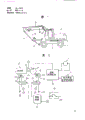
Fig. 1 represents the control system-hydraulic crawler excavator of a most preferred embodiment of the present invention, and it is made up of with the top revolving body 4 that is connected by the gyroscope wheel on chassis 23 chassis 2 with road wheel (a plurality of) 1; On top revolving body 4, be provided with the annex of forming by with hydraulic cylinder 5,6,7 separately-driven cantilevers 8, arm 9, scraper bowl 10 that is positioned at front end.Road wheel 1 by hydraulic motor 11(referring to Fig. 2) drive.Gyroscope wheel 3 is by the fluid motor-driven of not drawing among the figure.Below, when being called hydraulic cylinder 5,6,7 and hydraulic motor, these can be called executing agency (a plurality of) simply.
Be contained in the interior control system of above-mentioned hydraulic crawler excavator as shown in Figure 2, it is motor 12 that this control system has prime mover, control the number rotaring controller 13 of these motor 12 revolutions, by engine-driven volume adjustable hydraulic pump 14, control the control device of the output discharge capacity of this hydraulic pump 14, i.e. the adjuster 15 of pump; On the oil-out of hydraulic pump 14, by control valve assembly 16, connecting walk hydraulic motor 11 and the executing agency's assembly 17 that is positioned at frontal attachments, they are driven by the pressure oil of hydraulic pump 14 outputs.Here, hydraulic pump 14 is a Wobble plate pump, control output discharge capacity can adopt the inclination angle method of control swash plate, each control valve of control valve assembly 16 is with the joystick manipulation of not representing in the corresponding figures, in executing agency's assembly 17, except the hydraulic cylinder 5,6,7 that is positioned at frontal attachments, also comprise the hydraulic motor that turns round usefulness.
Relevant with number rotaring controller 13, be provided with maximum revolution changeable device 18, its maximum revolution that can make prime mover 12 changes between also big the 2nd grade of maximum revolution NP at the 1st grade of maximum revolution NE with than it; Relevant with pump control mechanism 15, be provided with maximum pump discharge changeable device 19, its maximum pump discharge that can make hydraulic pump 14 changes between also big the 2nd grade of maximum pump discharge at the 1st grade of maximum pump discharge qE and than it.Making becomes NE * qE ≈ NP * qP and concerns like that between maximum value NP, NE, qE, the qP, maximum revolution changeable device 18 will be designed to like that with maximum output displacement variation device 19.
As shown in Figure 3, number rotaring controller 13 has the lever 13a that is bearing in assigned position, with among the figure not the throttle valve lever 13b that links to each other with governor of expression be connected the mid point of lever 13a.At the top of lever 13a spring 13c is arranged, the other end of spring 13c links to each other with the end of the lever 13d that is bearing in assigned position.The other end of lever 13d links to each other with engine control lever 13f by for example hawser 13e.By this engine control lever 13f, can be in the scope below the 1st grade of maximum engine revolution NE, from dallying to the revolution of NE continuous control motor.
Here, the 1st grade of maximum revolution NE of motor is the inclination angle at pump 14, when promptly exporting discharge capacity and being qE, obtain the speed of 35km/h when walking on flat road with minimum power and carry out with desirable speed that the situation of digging operation makes decision, NE and qE are maximum revolution and the maximum output discharge capacity that is suitable for light load.Maximum revolution changeable device 18 has the 18a of executing agency that can control the lever angle of revolution, in engine revolution surpasses the scope of NE, and the 18a of executing agency, like that, control lever 13a reaches maximum angle of revolution shown in Fig. 3 (c).Motor can the 2nd grade of maximum revolution NP running.
Here, the 2nd grade of maximum revolution NP of motor is the inclination angle at pump, when promptly exporting discharge capacity and being qP, with minimum power, walking the time obtains that the condition of the speed of 35km/h makes decision on having desirable slope road, and NP, qP are maximum revolution and the maximum output discharge capacity that is suitable for high loaded process.
Moreover, the idling conditions of Fig. 3 (a) expression motor, the state when Fig. 3 (b) expression is controlled at the value NE of defined with the engine control lever with engine revolution, Fig. 3 (c) represents the throttle full open state.
In the present embodiment, when the engine control bar is pulled to extreme position, just obtain surpassing the value NE ' of engine revolution maximum value NE, even at this moment there is the 18a of executing agency to drive, the engine control bar can not move yet.
Also have, as shown in Figure 2, the 18a of executing agency links to each other with oil pressure source 22 and fuel tank 23 by electromagnetic valve 18b.
As shown in Figure 4, the adjuster 15 of pump has the piston 15a that the swash plate by linkage and hydraulic pump 14 links to each other, the 15b of executing agency, when the 15b of executing agency is connected with aforementioned link mechanism, can be communicated with above-mentioned oil pressure source 22 and fuel tank 23 selectively by servo valve 15c, again, maximum output displacement variation device 19 is equipped with the piston 15a of the 15b of executing agency pump control mechanism 15 in to be extended, have the 19b of executing agency of piston 19a and make the 19b of executing agency selectively with the electromagnetic valve 19c of oil pressure source 22 and fuel tank 23 connections.
Moreover, referring to shown in Figure 2, symbol 21 is by for example, the control device that microcomputer constitutes, on its input port, connecting engine rotation sensor 20, it provides the device of relevant executing agency operating condition information, is that the running according to engine output shaft determines.On the delivery outlet of control device 21, connecting electromagnetic valve 18b and electromagnetic valve 19c.Electromagnetic valve 18b, 19c control according to the program of Fig. 5.When engine revolution when the 1st maximum value NE is following, two electromagnetic valve 18b, 19c degaussing (disconnection), when engine revolution surpasses the 1st maximum value NE, two electromagnetic valve 18b, 19c excitation (connection).
Secondly, relevant program of in control device 21ROM, storing in advance, we are illustrated with reference to Fig. 5.
At first, at step S1, the signal according to engine rotation sensor 20 outputs reads in engine revolution NO.When proceeding to step S2, with the revolution NO that read in in ROM in advance the 1st grade of maximum revolution NE of the motor of storage compare.If the signal of sensor 20 outputs of the revolution NO that the expression motor is present surpasses the revolution NE that adapts with the light load running, then carries out step S3; If NO below NE, then carries out step S4.When step 3, electromagnetic valve 18b, 19c connect simultaneously, and when step 4, electromagnetic valve 18b, 19c disconnect simultaneously.
Like this, maximum revolution changeable device 18 is to constitute like this: when the revolution of the motor of being controlled by number rotaring controller 13 12 surpasses the 1st grade of maximum revolution NE, just further change its revolution; The output signal of 21 pairs of revolution speed detecting devices 20 of control device responds, when the revolution of motor 12 is the 1st grade of maximum revolution NE and than its also little revolution, the maximum output discharge capacity of hydraulic pump 14 is got the 2nd grade of maximum pump discharge qE, when revolution maximum revolution of motor 12 above the 1st grade, the maximum output discharge capacity of hydraulic pump reduces, the maximum revolution of motor 12 be to increase simultaneously, maximum revolution changeable device 18 and maximum output displacement variation device 19 regulated like this.Particularly point out a bit, in the present embodiment, control device 21, maximum revolution changeable device 18 and maximum output displacement variation device 19, when the revolution of motor 12 discontinuously during maximum revolution above the 1st grade, when the maximum output discharge capacity with hydraulic pump 14 changes to the 1st maximum value qP, the maximum revolution of motor 12 be changed the 2nd grade of maximum revolution NP, and they connect each other.
The effect with regard to present embodiment now describes.
(1) engine revolution is in the 1st grade of situation below the maximum revolution NE that is suitable for the light load running
When engine revolution when the 1st the maximum value NE that adapts with low load operation is following, electromagnetic valve 18b, 19c disconnect simultaneously, the 19a of executing agency of pump inclination maximum control usefulness did not act on the 18a of the executing agency while of engine revolution control usefulness.Therefore, with the supposition of the maximum of
pump 14 output discharge capacity in the 2nd grade of maximum pump discharge qE that adapts with low load operation, the revolution of motor also reaches the value that the manipulated variable with the other engine control bar 13f of operating seat adapts.N-Q curve in this case represents that with the solid line of Fig. 6 the P-Q curve was represented with chain-dotted line shown in Figure 7 when engine revolution was NE.In addition, Fig. 8 represents not adopt the example of P-Q line chart of the hydraulic pump in the past of the such inclination maximum switching controls of the present invention.In example in the past, when engine revolution drops to NO ' time from NO, pump oil transportation amount is also from Q
Drop to Q
'.Like this, it is just impossible to improve the oil consumption of general job speed.
(2) engine revolution surpasses the situation of the 1st grade of maximum revolution NE that adapts with the light load running
When engine control bar 13f was pulled to extreme position, engine revolution reached the revolution NE ' above NE, and electromagnetic valve 18b, 19c connect simultaneously, and 18a of executing agency and 19a act on simultaneously.Therefore, in the 1st maximum value qP(that supposition of the maximum of pump 14 output discharge capacity and high load capacity adapt<qE), such shown in Fig. 3 (c), engine revolution is controlled in the 2nd grade of maximum revolution NP that adapts with the heavy load running, the i.e. maximum number of revolutions of motor under the load.The state of N-Q curve at this moment represents that with the P point of Fig. 6 the P-Q curve is represented with solid line P in Fig. 7.
Here, because maximum output discharge capacity qE, qP and maximum engine revolution NE, NP, such as mentioned previously, determine by following formula
qE×NE≈qP×NP
But qE>qP, NE<NP, therefore when above-mentioned engine revolution exchanged with maximum output discharge capacity, it is certain that the oil transportation amount of pump can probably keep.
Like this, if adopt present embodiment, for example work as wheeled hydraulic excavator and begin climbing, throttle lever is opened, when engine revolution surpassed the 1st grade of maximum value NE, the 18a of executing agency made motor spray (oil), and its revolution becomes the 2nd grade of maximum revolution NP, meanwhile, the 1st grade of maximum pump discharge qP that the inclination maximum of pump swash plate becomes and the 2nd grade of maximum pump discharge qE below revolution NE is also little adapts.Like this, the power output of motor and the input power of pump all reach maximum value, and wheeled hydraulic excavator can often be kept desirable speed, for example 35km/h climbing.In contrast, when engine revolution under the situation below the NE, during the maximum output of regulation discharge capacity qE, the pump input power that its result just becomes with walking on flat road or the light load running when gently excavating adapts, motor can turn round in the favourable scope of oil consumption.Because the revolution running of motor below NE, certainly, noise has just reduced.
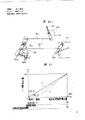
Characteristic curve referring now to motor shown in Figure 9 is illustrated this point again.Among the figure, A
1The pairing engine revolution of revolution NP-power characteristic line that the climbing walking of expression and high loaded process adapts, A
2The revolution NE that the smooth road walking of one of expression and low load operation situation adapts
1Corresponding engine revolution-power characteristic line, A
3The revolution NE that the another kind of situation-digging operation of expression and low load operation adapts
2Corresponding engine revolution-power characteristic line.B
1The pairing engine revolution of revolution NP-torque characteristics line that the slope road walking of expression and high loaded process adapts, B
2The revolution NE that the smooth road walking of one of expression and low load operation situation adapts
1Corresponding engine revolution-torque characteristics line.B
3The revolution NE that another situation-digging operation of expression and low load operation adapts
2Pairing engine revolution-torque characteristics line.C
1The pairing oil consumption characteristic line of revolution NP that the slope road walking of expression and high loaded process adapts, C
2The revolution NE that the smooth road walking of one of expression and low load operation situation adapts
1Pairing oil consumption characteristic line, C
3The revolution NE that the another kind of situation-digging operation of expression and low load operation adapts
2Pairing oil consumption characteristic line.Also has Ps
1Desired power when walk in the slope road of expression high loaded process, Ps
2Desired power when walk in the smooth road of one of expression low load operation situation, Ps
3Desired power during the another kind of situation-digging operation of expression low load operation.
As can be seen from Figure, be assumed to NE as the 1st grade of maximum revolution NE engine revolution
1The time, can obtain A
2Such engine revolution-power characteristic line, oil consumption becomes C
2Like that, therefore, with required power P s
2Oil consumption when walking on smooth road is g
2Corresponding, suppose that maximum revolution is NP, when carrying out same running, revolution rises to N
2Oil consumption becomes g
2'.Therefore, oil consumption is from g
2' become g
2The time, engine revolution is from N
2Be reduced to NE
1, noise has also improved.When the 1st grade of maximum revolution NE of engine revolution is assumed to NE
2, when carrying out digging operation, oil consumption is from g
3' become g
3, engine revolution is also from N
3Be reduced to NE
2, noise has also improved.
As shown in Figure 7, because the maximum oil transportation amount of the pump QP that each numerical value is maximum oil transportation amount QE of the pump when being NE according to engine revolution and engine revolution when being NP decides about equally, therefore, even maximum output discharge capacity switches to qP from qE during walking, the speed of travel is also constant, is preferably from the stand under load situation that turns round.
Moreover, because the change of operating condition only surpasses the 1st grade of maximum revolution NE or carries out in also little than it in engine revolution, so the bad phenomenon such as variation of hydraulic pump oil transportation amount that are accompanied by the change generation of operating condition can not produce fully.Because pump oil transportation amount does not increase, therefore,, on flat road, to walk even still keep original state, its speed of travel can not surpass normal speed yet.
Secondly, with reference to figure 2 and Figure 10, the 2nd embodiment of the present invention is described.
In the 1st embodiment, according to the revolution of the signal measuring motor of tachometer generator 20 output, when measuring revolution by its and surpassed NE, the maximum output discharge capacity of hydraulic pump becomes qP by qE, and maximum engine revolution becomes NP by NE; In the present embodiment, be provided with state selecting switch, utilize the switching position of engine revolution and state selecting switch to carry out and above-mentioned same control.
Here it is, supposes the power rating of economic scene with the heavy load running usefulness of light load running usefulness, utilizes the state selecting switch 25 of Fig. 2 double dot dash line shown in interior, can select any state.In the time of on state selecting switch 25 being placed on power rating chosen position P, the power output status signal; In the time of on it being placed on economic scene chosen position E, output economical running signal.
Therefore, handling procedure that need not be shown in Figure 5, and carry out the swash plate inclination maximum of pump and the control of motor according to handling procedure shown in Figure 10, promptly in the S12 step, by expression engine revolution N
0Detection signal and status signal differentiate, only surpass the 1st grade of maximum revolution NE and be when power rating is selected in engine revolution, the maximum of pump output discharge capacity ability is changed to qP from qE, meanwhile, the maximum value of engine revolution just is changed to NP, carries out power state transition.Under condition in addition, the maximum delivery volume of pump still remains qE, and engine revolution is controlled on the numerical value that the manipulated variable with engine control bar 13f adapts.
If adopt such formation, select economic scene by state selecting switch, and this is wrong when light load turns round, system still can promptly turn round under engine revolution NP, the maximum delivery volume qP of pump at power rating.
More than be to get walking at a high speed as high loaded process, get that low speed walking or digging operation illustrate as low load operation, yet, the present invention is not limited only to this, for example, as high loaded process, light digging operation is as low load operation heavy digging operation, and the variation that the present invention is applied to this operating condition also is fine.
More than be with regard to wheeled hydraulic excavator embodiments of the invention to be described, the present invention also can be applicable to crawler hypraulic excavator.Particularly in this case, that is, it also is good using effect of the present invention for heavy digging operation with the transformation of the operating condition of light digging operation.
In the above description, be the judgement of carrying out engine revolution according to programs in the control device 21, still,, also can judge with comparator without program.In addition, without tachometer generator 20, and on the throttle lever on engine control bar 13f other driver's seat or motor next door moves to above the position of the 1st grade of maximum revolution NE of engine revolution the time, utilize change-over switch to constitute the revolution that revolution sensor also can be judged motor indirectly.
Moreover, utilize hydraulic cylinder 18a to improve the revolution of motor here, also available electromagnetic actuator carries out.Also have, the available too electromagnetic actuator of the control of inclination maximum carries out.At this moment, utilizing the output signal of tachometer generator 20 directly to drive electromagnetic actuator also is fine.
The possibility that more than illustrates about the concrete formation of change embodiment, though clear not enough, also be to be suitable for fully in other embodiment.
The the 3rd~6th embodiment
Below, with reference to Figure 11 to Figure 18 other embodiment of the present invention (a plurality of) are described.Figure 11 adopts identical symbol on same parts to embodiment (a plurality of) shown in Figure 180 and other embodiment, so explanation can be omitted.
The embodiment of Figure 11 to Figure 18 constitutes like this: control device 39,42,47, maximum revolution changeable device 38,41,13 and maximum output displacement variation device 37 surpass the 1st grade of maximum revolution N when the revolution of motor 12 is continuous
EThe time, in 1 grade of maximum pump discharge qP of maximum output displacement variation to the of hydraulic pump 14, the maximum revolution of motor 12 fades to the 2nd grade of maximum revolution N
P, and also different aspect being mutually related with aforesaid embodiment.
The 3rd embodiment
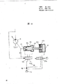
At first, referring to Figure 11 to Figure 14, the 3rd embodiment of the present invention is described.In the control system of this embodiment, variable pump 14 links to each other with running motor 11 by control guiding valve 30, quantitative hydraulic pump 31 links to each other by control valve 33 that is driven by the walking pedal 32 that constitutes walking operation apparatus and the reversal valve of being handled by forward-reverse bar 34 35 actuation holes 30a, the 30b with control guiding valve 30.In addition, between quantitative hydraulic pump 31 and control valve 33, choke valve 36 is arranged, the pressure of choke valve 36 front and back, can supply with the 37a(of executing agency of maximum output displacement variation device 37 referring to Figure 12 by electromagnetic valve 37b) on the other hand, the advance pressure of input port of walking one side of the manipulation of running motor 11 is by the electromagnetic valve 38b fuel feeding that links to each other with pipeline 60 38a of executing agency to motor maximum revolution changeable device 38.The 38a of executing agency of this motor maximum revolution changeable device 38, the same with the angle of revolution of aforesaid control lever 13a shown in Figure 3, relevant with number rotaring controller 13.As shown in figure 11, spring 38c is installed in the 38a of executing agency, because the effect of spring surpasses N in engine revolution
EScope in, the 38a of executing agency makes engine revolution increase and increase corresponding to the advance pressure of a side entrance of the manipulation of hydraulic motor 11.
As shown in figure 12, the structure of pump control mechanism 15 is identical with the controller structure of the 1st embodiment shown in Figure 4.Maximum output displacement variation device 37 has the piston 37c that can pick out on the piston 15a of the 15b of executing agency of pump control mechanism 15, and being included in the 37a of executing agency that inside is provided with spring 37d, the pressure that is produced is that choke valve 36 front and back have the pressure oil of pressure reduction by the electromagnetic valve 37b inflow 37a of executing agency.
Tachometer generator 20 constitutes the revolution determinator, links to each other with the inlet of control device 39, utilizes the 1st grade of maximum revolution N of following programmed decision engine revolution
ESize.Electromagnetic valve 37b, 38b link to each other with the delivery outlet of control device 39, when engine revolution surpasses the 1st grade of maximum revolution N
EThe time, two electromagnetic valve 37b, 38b excitation, pressure oil feeds the 37a of executing agency, 38a thereafter.
Referring to Figure 13, in other words,, read in engine revolution No according to the signal of tachometer generator 20 output at step S1, when step S2, judge this engine revolution No and the 1st grade of maximum revolution N of the engine revolution of storage in advance in ROM
EThe size of (corresponding to the maximum revolution of motor light load running).If engine revolution No surpasses N at present
E(No>N
E), then enter into step S3; If No is at N
EBelow (No<N
E), then enter into step 4, when step S3, electromagnetic valve 37b, 38b connect, and when step 4, electromagnetic valve 37b, 38b disconnect.
The effect of explanation present embodiment now.
(1) engine revolution is being suitable for light load the 1st grade of maximum revolution N that turn round most
EFollowing situation.
With reference to Fig. 1-Figure 10, can carry out the control same with the above embodiments.Promptly N-Q line chart as shown in figure 14 is such, and pump oil transportation amount Q and engine revolution N increase pro rata.Engine revolution is at N
EPressure P when following-flow Q line chart is represented with the chain-dotted line E among Fig. 7.
(2) engine revolution surpasses the 1st grade of maximum revolution N corresponding to the light load motion
ESituation.
When maneuvering engine control lever 13f(referring to Fig. 3), make engine revolution surpass the 1st grade of maximum revolution N
EThe time, electromagnetic valve 37b excitation, the pressure that is produced is pressure oil two inlets of the 37a of executing agency that uses of inflow pump inclination maximum control device respectively that choke valve 36 front and back have pressure reduction.Because the pressure differential of choke valve 36 front and back can be used the oil transportation amount of quantitative hydraulic pump 31, promptly therefore the function representation of engine revolution, can control engine revolution at the 1st grade of maximum revolution N
ETo the 2nd grade of maximum revolution N
PBetween, the output discharge capacity is between qE to pP, corresponding to the continuous minimizing of engine revolution.At this moment, the intensity by suitably determining the spring 37d in the 37a of executing agency and the amount of restriction of choke valve 36, shown in the N-Q line chart of Figure 14 like that, in engine revolution greater than N
EScope in, the oil transportation amount that makes pump is for certain.Engine revolution is N
PThe time pressure P-flow Q line chart represent with the solid line P among aforesaid Fig. 7.
Like this, under the present embodiment situation, can obtain the action effect same with the embodiment of Fig. 1 to Figure 10.In the present embodiment, owing to work as engine revolution at the 1st grade of maximum revolution N that is being suitable for the light load running
EIn the following low power ranges, maximum output discharge capacity is got the qE value, and is surpassing N
EHigh power range in, according to the load of hydraulic motor 11, engine revolution is increased, meanwhile, along with the increase of engine revolution, the inclination maximum of pump reduces, maximum output discharge capacity can reduce continuously from qE, therefore, when engine revolution surpasses N
EThe time, the maximum value of the maximum value of engine revolution and output discharge capacity changes sharp, and operating characteristics degenerates, and can cause the fault of machine.
The 4th embodiment
With reference to Figure 15, the 4th embodiment described.In the present embodiment, use pressure sensor 40 to measure the pressure of the preceding import of hydraulic motors 11, surpass the 1st grade of maximum revolution N in engine revolution
EScope in, control the revolution of motor according to the output voltage of pressure sensor 40, about other structures and the 3rd embodiment identical.
That is, in maximum revolution changeable device 41, without hydraulic cylinder 38a, and with for example, linear electromagnet device 41a control lever 13a(is referring to Fig. 3) the angle of revolution.The output voltage of pressure sensor 40 is sent in the Control Component 42, and Control Component 42 is controlled the maximum value of engine revolution by to linear electromagnet 41a output signal correspondingly.
In the present embodiment, because in case the output voltage of pressure sensor 40 is imported Control Component 42, can obtain being sent to the signal of linear electromagnet 41a according to this input voltage, therefore, under the very fierce situation of the pressure oscillation on the advance side input port of hydraulic motor 11, the maximum value of engine revolution can not change along with this change, and effect is relatively good.
The 5th embodiment
With reference to Figure 16, the 5th embodiment described.Present embodiment is illustrated in to excavate and uses situation of the present invention in the loop.Surpass N in engine revolution
EScope in, according to inlet, the outlet pressure of the hydraulic cylinder of digging action, the maximum value of control engine revolution.
That is, the hydraulic cylinder 43 of digging action links to each other with control guiding valve 30, and going into, export by stop valve 44 of hydraulic cylinder 43 links to each other with electromagnetic valve 38b.Like this, control guiding valve 30 carries out switching controls by the control valve 45 of digging action, the pressure oil that this valve 45 is accepted by constant displacement pump 31 supplies.About other structures and shown in Figure 11 identical.
Even in the present embodiment, engine revolution is at N
EIn the following scope, maximum revolution changeable device 38 is not worked with maximum output displacement variation device 37, the engine control bar 13f(on the also available driver's of the being located at seat of engine revolution side is referring to Fig. 3) control, the inclination maximum of hydraulic pump 14, maximum output discharge capacity remains qE, its result, revolution N-flow Q line chart as shown in Figure 14.Moreover, be N at revolution
EThe time pressure P-flow Q line chart represent with the chain-dotted line E of Fig. 7.
On the other hand, surpass N in engine revolution
EScope in, maximum revolution changeable device 38 and 37 work of maximum output displacement variation device, the maximum value of engine revolution is along with inlet, the outlet pressure of the hydraulic cylinder 43 that excavates usefulness increase and improve, the maximum of hydraulic pump 14 output discharge capacity is also along with the oil transportation amount of hydraulic pump 31, that is, engine revolution increases and reduces.At this moment, the same with above-mentioned situation, the oil transportation amount of hydraulic pump 14 is certain, and maximum output discharge capacity is controlled.
Present embodiment also can obtain and the 3rd the identical effect of embodiment.It can automatically separate the 1st grade of maximum revolution N using engine revolution to surpass to be suitable for the light load running by heavily excavating
EScope and use N by light excavation
EFollowing scope, the motor output that adapts and the input power of pump can obtain and load.Therefore, can be provided in oil consumption, noise, the extremely superior hydraulic crawler excavator control system of operating characteristics everyway.
In addition, same with the 4th embodiment, also the available pressure sensor is measured inlet, the outlet pressure that excavates with hydraulic cylinder 43.
The 6th embodiment
Figure 17 represents the 6th embodiment of the present invention.In the present embodiment, engine revolution is not set and surpasses the 1st grade of maximum revolution N
EThe time engine revolution control and the such special changeable device of device 38,41 of the 3rd to the 5th embodiment; Engine revolution is at N
EFollowing control is still carried out with same number rotaring controller 13, about other structure comes down to identical with the 3rd to the 5th embodiment.
Tachometer generator 20 links to each other with the input port of the control device of representing with symbol 47, and electromagnetic valve 37b links to each other with delivery outlet.In addition, stored program shown in Figure 180 on the ROM in control device 47 in advance, according to the engine revolution difference, corresponding connection of electromagnetic valve 37b or disconnection.
With reference to Figure 18, when step S1, reads 51a according to the signal of tachometer generator 20 outputs and be placed on maximum position, and hydraulic cylinder 52a represents the situation of pinch in that at this moment motor 12 is with the 1st grade of maximum revolution N
ERotate.Figure 20 (c) expression hydraulic cylinder 52a is from the situation of Figure 20 (b) elongation, and the 2nd intermediate bar 51d only rotates the amount of the elongation of a hydraulic cylinder 52a, and motor is with the 2nd grade of maximum revolution N
PRunning.
With reference to Figure 21, be described in detail the manipulated variable of engine control bar 51a and the relation of engine revolution and hydraulic pump oil transportation amount.
In the economic scene that makes hydraulic cylinder 52a pinch in, when making engine control bar 51a be in the position of diagram " disconnection E ", motor stops.If will think zero in the engine revolution of this " disconnection E " position, then arrive maximum position (referring to Figure 20 (b)) from " disconnecting E " position by maneuvering engine control lever 51a, can control engine revolution from the zero N that reaches
EIn addition, if at this moment pump output discharge capacity qE be certain, then adjustablely save hydraulic pump oil transportation amount that chain-dotted line represents from the zero Q that reaches
0Moreover, Figure 20 (a) expression engine control bar 51a is in the state of " disconnecting P " position, can find out that by Figure 20 (a) and Figure 21 when hydraulic cylinder 52a was in the state of pinch in, the scope from " disconnecting E " to " disconnecting P " became the working clearance of engine control bar 51a.
When making hydraulic cylinder 52a be in the power rating of elongation, when making engine control bar 51a be in " disconnecting P " position of Figure 21, prime mover stops.If think that the engine revolution in " disconnecting P " position is zero, then reach maximum position (referring to Figure 20 (c)) from " disconnecting P " position by maneuvering engine control lever 51a, can control engine revolution and change to N from zero
PAt this moment, if pump output discharge capacity qP is certain, then can controls the hydraulic pump oil transportation amount of representing with solid line P and reach Q from zero
0
Here, because the 1st grade of maximum revolution N of engine revolution
EBe when the pump swashplate angle, when promptly exporting discharge capacity and being qE, can obtain the speed of 35Km/h when on flat road, walking with the minimum power of necessity, or carry out with desirable speed that digging operation decides, the signal of the proportional increase of payload of pressure actuator 11,43.
Moreover, when measuring the load of hydraulic actuating mechanism 11,43, be not only limited to mensuration pressure, also can detect poor by the revolution of engine control bar indication and actual revolution, be the revolution deviation, on hydraulic motor gyroaxis etc., paste foil gauge, also can measure actual load.
Secondly, in the 4th embodiment, also can in the maximum output discharge capacity control of hydraulic pump, adopt the electromagnetic actuator that in maximum revolution control, uses.
The the 7th to the 9th embodiment
Below, with reference to Figure 19 to Figure 26 the of the present invention the 7th to the 9th embodiment is described.Among the embodiment that illustrates among the figure and the 7th to the 9th embodiment, all adopted same symbol in the past for same parts.
The hydraulic pump of the 7th to the 9th embodiment and motor 12 are control like this: the operating condition information of 53,56 pairs of information provider units of control device, 25,54,55 outputs responds, when this information is represented low load operation, the maximum output discharge capacity of hydraulic pump 14 is got the 2nd grade of maximum pump discharge qE, and the revolution of motor 12 is the 1st kind of combination of little revolution; When this information was represented high loaded process, the maximum of hydraulic pump output discharge capacity was got the 1st grade of maximum pump discharge qP, and the revolution of motor 12 is the 2nd kind of combination of big revolution; Aspect adjusting revolution changeable device 52 and maximum output displacement variation device 19, different with former embodiment.
The 7th embodiment
Figure 19 represents the 7th embodiment of the present invention, the delivery outlet of the volume adjustable hydraulic pump 14 that drives by the motor 12 that constitutes prime mover by control slide valve assembly 16 with include running motor, excavation links to each other with the actuator 50 of hydraulic cylinder (hydraulic cylinder 5~7 of Fig. 1), rotary motor.Control guiding valve 16 usefulness control sticks (not marking among the figure) carry out switching controls.
The output discharge capacity of volume adjustable hydraulic pump 14 is by pump control mechanism 15, go into the revolution No of motor according to circuit pressure, when step S2, differentiate this engine revolution No and the 1st grade of maximum revolution N of engine revolution of storage in advance in ROM
ESize.If present engine revolution No surpasses the 1st grade of maximum (top) speed N
E(No>N
E), then enter into step S3; If at N
EBelow, then enter into step S4.When step S3, electromagnetic valve 37b connects, and when step S4, electromagnetic valve 37b disconnects.
About the effect of present embodiment, when engine revolution is being suitable for the 1st grade of maximum revolution N that light load turns round
EWhen following, identical with former embodiment, suppose that maximum output discharge capacity is qE, the manipulated variable that engine revolution reaches with the other engine control bar 13f of operating seat is worth accordingly.
Surpass the 1st grade of maximum revolution N that turns round corresponding to light load when engine revolution
EThe time, electromagnetic valve 37b excitation, same with the 3rd to the 5th embodiment, engine revolution can be from the 1st grade of maximum revolution N
ETo the 2nd grade of maximum revolution N
PBetween, maximum output discharge capacity can reduce to control according to engine revolution continuously between the qE to qP.Like this, like that, engine revolution is than N shown in the revolution N-flow Q curve map of Figure 14
EIn the big scope, it is certain that pump oil transportation amount keeps.
In the present embodiment, because the control of the gamut of engine revolution is undertaken by control stick 13f, therefore simple in structure, operating characteristics is fine simultaneously.
In the above the 3rd to the 6th embodiment, represented when the control of the maximum output of hydraulic pump discharge capacity, not use the example of the hydraulic circuit pressure of the executing agency 11,43 that operation uses; As motor maximum revolution control is adopted among the 3rd to the 5th embodiment, the control of the maximum output of hydraulic pump discharge capacity also can utilize the pressure of this hydraulic circuit.Can take out hydraulic motor 11 or hydraulic cylinder 43 and the hydraulic pressure of control between the guiding valve 30 pressure as hydraulic circuit, as representing with double dot dash line among Figure 15, pressure sensor 46 is connected between control guiding valve 30 and the hydraulic pump 14, measure the output pressure of hydraulic pump, can obtain and hydraulic control system equally, the maximum output of its maximum output discharge capacity utilization displacement variation device 19 is regulated.This changeable device 19 has hydraulic actuating mechanism 19a, utilizes its flexible maximum output discharge capacity of each commentaries on classics of pump that can make to divide the two-stage to carry out switching controls.This hydraulic actuating mechanism 19a links to each other with pressure source 22 or fuel tank 23 by electromagnetic valve 19c.
The revolution of motor 12 is regulated by the number rotaring controller 51 that comprises control lever (referring to Figure 20), the revolution changeable device 52 that can obtain big revolution and little revolution is relevant with number rotaring controller 51, no matter the revolution of being regulated by number rotaring controller 51 how, only make its revolution change a given amount.
If narration in more detail, shown in Figure 20 (a)~(c), revolution changeable device 52 is governor choke valve lever 51b of the motor 12 of the engine control bar 51a other with being located at the driver's seat, and middle lever 51c constitutes one.Number rotaring controller 51 is made of engine control bar 51a, governor throttle valve lever 51b, intermediate bar 51c, 51d.With reference to Figure 20 (a), engine control bar 51a is bearing on the other console housing 53 in driver's seat, and it links to each other with an end that is bearing in locational the 1st intermediate bar 51c of vehicle specifies by hawser 51e.The 1st intermediate bar 51c slightly is "<" font, is fixing the hydraulic cylinder 52a of revolution changeable device 52 at its other end.The 2nd intermediate bar 52d with the same axle upper support of the 1st intermediate bar 51c, by hydraulic cylinder 52a, the revolution of the 1st intermediate bar 51c passes to the 2nd intermediate bar 51d.Like this, the 2nd intermediate bar 51d links to each other with timing throttle valve rod 51b by hawser 51f.Hydraulic cylinder 52a is communicated with hydraulic power source 22 and fuel tank 23 by electromagnetic valve 18b.
Among Figure 20 (a), engine control bar 51a is in open position, and hydraulic cylinder 52a represents the situation of pinch in, and at this moment motor 12 stops.Even during hydraulic cylinder 52a elongation, the 2nd intermediate bar 51d does not rotate.Among Figure 20 (b), engine control bar so N
EWith qE is to export discharge capacity corresponding to the maximum revolution of light load running with maximum.In addition, because the 2nd grade of maximum revolution N of engine revolution
PBe swashplate angle, when promptly exporting discharge capacity and being qP,, can obtain on desirable sloping road that the speed of 35Km/h decides during walking with the minimum power of necessity, therefore, N
P, q
PBe maximum revolution and the maximum output discharge capacity that is applicable to the heavy load running.
Secondly, on Figure 19, symbol 53 is for example to use, the control device that microcomputer is formed, and the state switch 25 that constitutes selecting arrangement links to each other with its inlet.State switch is the switch that can switch mutually on power rating position (P) and economic scene position (E), also can use, for example moment.Electromagnetic valve 19c links to each other with the outlet of control device 53 with electromagnetic valve 18b, and electromagnetic valve 19c links to each other with the hydraulic cylinder 19a of pump inclination maximum adjusting usefulness again, and electromagnetic valve 18b links to each other with the hydraulic cylinder 52a that engine revolution is regulated usefulness.The switching position of electromagnetic valve 18b and 19c and above-mentioned state switch 25 is echoed mutually, when state switch 25 switches to the power rating position, and electromagnetic valve 18b, 19c excitation, when switching to the economic scene position, electromagnetic valve 18b, 19c degaussing.
The below effect of explanation present embodiment.
(1) power rating running
When state switch 25 switches to the power rating position, electromagnetic valve 19c excitation, hydraulic cylinder 19a links to each other with pressure source 22, because like this, the hydraulic cylinder 19a action of illustrated maximum output displacement variation device 19, maximum output discharge capacity is assumed to qP because also excitation of the electromagnetic valve 18b of engine revolution changeable device 52 at this moment, hydraulic cylinder 52a elongation, if the engine control bar 51a other the driver's seat is pulled to extreme position, such shown in Figure 20 (c), by intermediate bar 51d, can make engine revolution increase to the 2nd grade of maximum revolution N
P
Therefore, in low pressure range (pressure P is below 2: referring to Figure 23), when the maximum output discharge capacity of restriction hydraulic pump 14 was qP, shown in Figure 22 solid line P, pump oil transportation amount and engine revolution increased pro rata, are the 2nd grade of maximum (top) speed N in the motor maximum number of revolutions
PThe time, can obtain maximum oil transportation amount Q
0Engine revolution N in this situation
PUnder pump pressure P-flow Q curve map become shown in Figure 23 solid line P like that.
(2) economic scene running
When state switch 25 switches to the economic scene position, electromagnetic valve 19c degaussing, hydraulic cylinder 19a is connected with fuel tank 23, and like this, maximum output discharge capacity becomes qE(>qP).Because electromagnetic valve 18b degaussing at this moment, hydraulic cylinder 52a pinch in, therefore, when the engine control bar 51a other in the driver's seat is pulled to extreme position, such shown in Figure 20 (b), because the revolution of the 2nd intermediate bar 51d has only reduced the indentation amount of a hydraulic cylinder 52a, engine revolution still is limited in the 1st grade of maximum revolution N
E(<N
P).
Therefore, in low pressure range (pressure P is below 1: referring to Figure 23), when the maximum oil transportation discharge capacity of hydraulic pump 14 was limited in qE, shown in the chain-dotted line E of Figure 22, pump oil transportation amount and engine revolution increased pro rata, were the 1st grade of maximum revolution N in engine revolution
EThe time, can obtain maximum oil transportation amount Q
0At this moment, at engine revolution N
EUnder pump pressure P-flow Q curve map shown in the chain-dotted line E of Figure 23.
Moreover the curve shown in Figure 23 dotted line is represented: when supposing that maximum output discharge capacity switches to qE, and the pressure P when engine revolution is brought up to the 2nd grade of maximum revolution NP-flow Q curve map.
(3) state switches running
When power rating turns round, when state switch 25 being switched to economic scene, electromagnetic valve 18b, 19c degaussing.Because like this, hydraulic cylinder 19c pinch in, the maximum output discharge capacity of hydraulic pump 14 becomes qE.In addition, because hydraulic cylinder 52a pinch in, the 2nd intermediate bar 51d follows its motion, is that counter-clockwise direction is rotated on Figure 20 (c), and therefore, engine revolution reduces by a setting.So no matter what scope is engine revolution be in, hydraulic pump oil transportation amount is all roughly kept necessarily, on rotational speed N-flow Q curve map, the arrow A direction along Figure 22 moves to economic scene from power rating.Owing to switch to power rating from economic scene, the action of each machine is with above-mentioned opposite, therefore, in the gamut of engine revolution, hydraulic pump oil transportation amount is all roughly kept necessarily, on rotational speed N-flow Q curve map, is to move to power rating from economic scene along the arrow B direction of Figure 22.
In the present embodiment, increase when in economic scene in the maximum oil transportation discharge capacity qE(of pump>qP), engine revolution still is limited in the 1st grade of maximum revolution N
E(<N
P), Q is measured in the maximum oil transportation of pump
0, like this, just making when the maximum oil transportation amount of pump, the operating speed that comprises economic scene and the speed of travel of power rating simultaneously can be identical.Can find out that for example, can obtain power demand PS2 in engine revolution during for NE1, oil consumption can be reduced to g2 with reference to above-mentioned Fig. 9, noise also reduces simultaneously.On the other hand, when pump oil transportation amount be Q
0The time, can obtain maximum speed 35km/h, find out by Figure 23, when economic scene, the pump output pressure is at (the essential pressure when for example walking on flat road) below the P1, speed walking with 35km/h is possible, yet when climbing, the output pressure of pump surpasses P1, at this moment just can not with the speed walking of 35km/h, but under power rating, the pump output pressure less than P2(for example, ramp angle is the essential pressure in slope when walking of θ), it is possible walking with the speed of 35km/h.
Therefore, in pump in the past, as present embodiment, make engine revolution be reduced to NE from N2
1(referring to Fig. 9), the input power of pump also reduces, and under the situation that oil consumption reduces, it is such that the maximum oil transportation volume of pump keeps certain P-Q curve map to become shown in above-mentioned Fig. 8 dotted line, and pump oil transportation amount is reduced to Q
8', can not get the speed of defined at last.
The 8th embodiment
With reference to Figure 24 the 8th embodiment of the present invention is described.The control system of present embodiment except the formation of the 7th embodiment, also is provided with load sensor 54, controls selector switch 55 automatically, and these load sensors 54 link to each other with the input port of automatic control selector switch 55 and controller 56.
Load sensor 54 is loads of measuring executing agency 50, in the illustrated embodiment, and with the pressure sensor formation that detects the pressure of hydraulic circuit between control guiding valve 16 and the executing agency 50.Identical with the situation of the above embodiments, also can adopt the sensor of detection of engine revolution deviation, the load of also available foil gauge measurement mechanical as load sensor.In addition, under the situation of detected pressures, also can measure the pressure of the pipeline between hydraulic pump 14 and the control guiding valve 16.
Automatically control selector switch 55 can switch to " manually " position and " automatically " position, and manual position is the switching of being undertaken by manual switchover by state switch 25 that power rating turns round or economic scene turns round; Automated location is to automatically switch according to the load of being measured by sensor 54.Therefore, control device 56 is just according to program switching controls electromagnetic valve 23 and 27 shown in Figure 25.
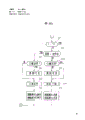
In Figure 25, when step S1, sensor 54 reads in the signal of state switch 25,55, when step S2, judges that switch 55 is manual position or automated location.If manual position, when step S3, state switch 25 judges it is power rating position or economic scene position again.If be the power rating position, when step S4, electromagnetic valve 18b, 19c are communicated with (excitation) simultaneously.If be the economic scene position, when step S5, electromagnetic valve 18b, 19c disconnect (degaussing) simultaneously.On the other hand, if change-over switch 55 is at automated location, then when step S6, judge detected load be on the set-point or under, if be on set-point, then enter step S4, if do not reach set-point, then enter step S5.
If the application present embodiment, except the advantage of the 7th embodiment, by selecting the automatic control position of change-over switch 55, operating condition can automatically switch, and does not need the operator to have very high qualification can carry out operation under best state.
The 9th embodiment
With reference to Figure 26, the 9th embodiment of the present invention is described.The control device of the control system of present embodiment, according to program shown in Figure 26 can control electromagnetic valve 18b, 19c,
Carrying out when executing agency's load fluctuates, can producing vibration under the auto state switching service behavior near set-point with the program shown in Figure 25 of the 8th embodiment.Figure 26 is in order to prevent to cause the program of vibration.
Adopt program shown in Figure 26, during according to the switching of variation control electromagnetic valve 18b, the 19c of executing agency load, before the elapsed time, load is indeclinable reaching, so state can keep, and can prevent to produce vibration.Suppose when step S2, selected automatic control, after step S7 judged that selector switch 55 switches, whether time t surpassed Ta preset time, when surpassing, only when judging, just enter step S8, judge that here whether the load of measuring surpasses set-point, if below set-point, then enters step S9, if more than set-point, then enter step S10.When step S9, S10, judge whether threshold sets, when not setting when just judging, when step S11, S12, remove the time of t computing time respectively, after, when step S13, threshold has set, and when step S14, threshold has been removed; On the other hand, when step S9, S10,, can directly enter step S13, S14 respectively when setting at threshold when judging, after, when step S15, electromagnetic valve 18b, 19c disconnect simultaneously, and when step S16, electromagnetic valve 18b, 19c connect simultaneously.Like this, can check executing agency's load before and after set-point, whether to change by judging threshold setting, when changing, count with regard to checkout time, reaching before given time, nonpassage of signal is arrived in the solenoid control loop, owing to begin to return, so even load variations, before given time, can keep former operating condition reaching.
Like this, in the present embodiment, utilize engine revolution changeable device 52, in the gamut of engine revolution, because with maximum output displacement variation the time, engine revolution can change between big value and little value, even therefore operating condition changes, pump oil transportation amount also can be constant.
In the above description, the maximum oil transportation amount Q of pump under each state
0(=q
P* N
P=q
E* N
E) equate, be set at q
P, N
P, q
E, N
EBut both are approximately equals, and homogeneity is not very good, and therefore, as index, for example the maximum speed of travel during each state has the difference of 30~35km/h.Be to utilize the maximum output discharge capacity of hydraulic cylinder control pump and the revolution of motor to change in the above description, yet use electromagnetic actuator also to be fine.Moreover, also can utilize linear electromagnet or a plurality of hydraulic cylinder to come by more than three stages or suppose inclination maximum continuously, corresponding therewith, also can control the revolution of motor, at this moment, can stipulate motor and hydraulic means the most rightly, improve oil consumption better according to various engine loads.In addition, do not use motor, and can use the present invention when adopting Motor Drive hydraulic pump 14 yet.In addition, adopt electronically controlled governor, by the emitted dose of increase and decrease fuel, the also revolution of changeable motor.In this case, hydraulic cylinder 52a and the 2nd intermediate bar 51d are useless.In addition, more than explanation that wheeled hydraulic excavator is done, on the big building machinery of other load changes, also all be suitable for.
In the above-described embodiments, the set-point that utilizes revolution changeable device 52 to regulate engine revolution is substantially equal to the definite value of the 1st grade of maximum revolution NE and the 2nd grade of maximum revolution NP, engine revolution reduces, thereby its set-point also reduces, revolution is at the 1st grade below the maximum revolution, when it changed, the oil transportation amount of pump also can change.