CN101046830B - Device for making part column and method for making part column - Google Patents
Device for making part column and method for making part column Download PDFInfo
- Publication number
- CN101046830B CN101046830B CN2007100887782A CN200710088778A CN101046830B CN 101046830 B CN101046830 B CN 101046830B CN 2007100887782 A CN2007100887782 A CN 2007100887782A CN 200710088778 A CN200710088778 A CN 200710088778A CN 101046830 B CN101046830 B CN 101046830B
- Authority
- CN
- China
- Prior art keywords
- column
- parts
- overlapping
- rows
- overlap
- Prior art date
- Legal status (The legal status is an assumption and is not a legal conclusion. Google has not performed a legal analysis and makes no representation as to the accuracy of the status listed.)
- Expired - Fee Related
Links
Images


Classifications
-
- G—PHYSICS
- G06—COMPUTING OR CALCULATING; COUNTING
- G06F—ELECTRIC DIGITAL DATA PROCESSING
- G06F30/00—Computer-aided design [CAD]
- G06F30/10—Geometric CAD
- G06F30/17—Mechanical parametric or variational design
-
- G—PHYSICS
- G06—COMPUTING OR CALCULATING; COUNTING
- G06F—ELECTRIC DIGITAL DATA PROCESSING
- G06F2111/00—Details relating to CAD techniques
- G06F2111/20—Configuration CAD, e.g. designing by assembling or positioning modules selected from libraries of predesigned modules
-
- Y—GENERAL TAGGING OF NEW TECHNOLOGICAL DEVELOPMENTS; GENERAL TAGGING OF CROSS-SECTIONAL TECHNOLOGIES SPANNING OVER SEVERAL SECTIONS OF THE IPC; TECHNICAL SUBJECTS COVERED BY FORMER USPC CROSS-REFERENCE ART COLLECTIONS [XRACs] AND DIGESTS
- Y10—TECHNICAL SUBJECTS COVERED BY FORMER USPC
- Y10S—TECHNICAL SUBJECTS COVERED BY FORMER USPC CROSS-REFERENCE ART COLLECTIONS [XRACs] AND DIGESTS
- Y10S715/00—Data processing: presentation processing of document, operator interface processing, and screen saver display processing
- Y10S715/961—Operator interface with visual structure or function dictated by intended use
- Y10S715/964—CAD or CAM, e.g. interactive design tools
Landscapes
- Physics & Mathematics (AREA)
- Geometry (AREA)
- Engineering & Computer Science (AREA)
- Theoretical Computer Science (AREA)
- General Physics & Mathematics (AREA)
- Pure & Applied Mathematics (AREA)
- Mathematical Optimization (AREA)
- Mathematical Analysis (AREA)
- Computer Hardware Design (AREA)
- Evolutionary Computation (AREA)
- General Engineering & Computer Science (AREA)
- Computational Mathematics (AREA)
- Processing Or Creating Images (AREA)
- User Interface Of Digital Computer (AREA)
- Management, Administration, Business Operations System, And Electronic Commerce (AREA)
Abstract
一种在CAD数据上进行由多行构成的零件栏(36)的制作的零件栏制作方法,在使用CAD的作图中,将零件栏和构成零件的重叠自动且适当地消除。检测零件栏(36)和其他形状要素(32)的重叠。在重叠被检测出时,将零件栏(36)的各行的高度压缩为(H1)。在即使将零件栏(36)各行的高度压缩为(H1)也产生零件栏(36)和其他形状要素(32)的重叠的情况下,求出零件栏(36)和形状要素(32)的重叠的行数。使重叠行数的部分分离且向和形状要素(32)不重叠的方向移动,分为分支前零件栏(36a)和分支出的零件栏(36b)。
A parts column creation method for creating a parts column (36) composed of a plurality of rows on CAD data, wherein overlapping between the parts column and constituent parts is automatically and appropriately eliminated in a drawing using CAD. Overlap of the part column (36) and other shape elements (32) is detected. When overlapping is detected, the height of each row of the parts column (36) is compressed to (H1). Even if the height of each row of the parts column (36) is compressed to (H1), in the case where the overlapping of the parts column (36) and other shape elements (32) occurs, the ratio of the parts column (36) and the shape elements (32) is obtained The number of overlapping rows. The parts overlapping the number of rows are separated and moved in a direction not to overlap with the shape element (32), and are divided into a part column before branching (36a) and a part column after branching out (36b).
Description
技术领域technical field
本发明涉及一种零件栏制作装置及零件栏制作方法,其进行在CAD数据上将多个构成零件的试样对应该构成零件用多个栏表示的零件栏的制作。The present invention relates to a parts column creation device and a parts column creation method for creating a parts column in which samples of a plurality of constituent parts correspond to the constituent parts in a plurality of columns on CAD data.
背景技术Background technique
近来,机械设计图、电气设计图及建筑设计图等许多已用CAD(Computer Aided Design)来完成。使用CAD时,就可将零件预先登记并进行分配,或移动已描绘的形状要素的配置,从而可容易地进行尺寸及形状的修正。Recently, many mechanical design drawings, electrical design drawings, and architectural design drawings have been completed with CAD (Computer Aided Design). When using CAD, it is possible to register and distribute parts in advance, or to move the arrangement of drawn shape elements, so that size and shape can be easily corrected.
设计图通常记载有图框、作为制作对象的形状要素的作图区域、记载一系列目录式事项的标题栏、将形状要素的多个构成零件的规格对应该构成零件表示于多个栏的零件栏。作图区域设在图框内的中央部,标题栏描绘在图框内的右下部。相对与此,零件栏记载于记载了形状要素与标题栏后的空白部分,例如描绘在图框内的右上部或左上部。A design drawing usually contains a frame, a drawing area for shape elements to be created, a title column for describing a series of bibliographic items, and parts in which the specifications of multiple constituent parts of shape elements correspond to the constituent parts in multiple columns. column. The drawing area is set in the central part of the frame, and the title bar is drawn in the lower right part of the frame. On the other hand, the parts column is described in a blank portion after the shape element and the title column are described, for example, it is drawn in the upper right or upper left of the drawing frame.
形状要素优选与图框、标题栏、零件栏等不重叠地明了地记载,但存在由于布置而产生重叠的情况。从该观点出发,在检测出作图区域与图框重叠的情况下,通过自动修正作图区域的配置而消除重叠,这一点已有提案(例如参照引用文献1)。Shape elements are preferably described clearly without overlapping with drawing frames, title blocks, parts fields, etc., but overlapping may occur due to layout. From this point of view, when overlapping of a drawing area and a frame is detected, it has been proposed to eliminate the overlap by automatically correcting the arrangement of the drawing area (for example, refer to Citation 1).
特许文献1:特开平7-182397号公报Patent document 1: Japanese Patent Application Laid-Open No. 7-182397
所述特许文献1记载的方法中,在检测出形状要素与图框重叠的情况下,单纯地将作图区域整体进行移动。因此可以想象,在零件栏大的情况下,用特许文献1记载的方法将作图区域向上下左右任一方向移动都不能消除重叠。In the method described in
发明内容Contents of the invention
本发明是考虑并解决了这样的问题的发明,提供一种零件栏制作装置及零件栏制作方法,其能够自动并且适当地消除零件栏与构成零件的重叠。The present invention considers and solves such a problem, and provides a parts column creation device and a parts column creation method capable of automatically and appropriately eliminating overlapping between a parts column and constituent parts.
本发明为关于零件栏制作装置的发明,具有以下的特征。The present invention relates to a parts column creating device, and has the following features.
第一方面是一种零件栏制作装置,进行在CAD数据上将形状要素的多个构成零件的规格对应于该构成零件用多行表示的零件栏的制作,其特征在于,具有:检测所述零件栏和其他形状要素的重叠的机构;在检测出有所述重叠时,求出所述零件栏的多行中和所述形状要素重叠的行数的机构;将所述重叠的行数的构成零件的部分从上述零件栏分离且移动到和所述形状要素不重叠的位置而制作新的零件栏的机构,并且,还具有在检测出所述重叠的情况下,压缩所述零件栏的各行的高度的栏压缩机构,仅在即使通过所述栏压缩机构将所述零件栏的各行的高度压缩到规定高度仍然产生重叠时,使所述重叠的行数部分向和所述形状要素不重叠的方向移动。The first aspect is a parts column creating device for creating a parts column in which the specifications of a plurality of constituent parts of a shape element are expressed in a plurality of lines corresponding to the constituent parts on CAD data, and is characterized in that it has: A mechanism for overlapping parts columns and other shape elements; when the overlap is detected, a mechanism for calculating the number of rows overlapping with the shape elements in the multiple rows of the parts column; The part constituting the part is separated from the above-mentioned part column and moved to a position not overlapping with the above-mentioned shape element to create a new part column, and when the overlap is detected, the above-mentioned part column is compressed. The column compression mechanism for the height of each row is configured so that the overlapped row number part is different from the shape element only when the row compression mechanism compresses the height of each row of the part column to a predetermined height and still overlaps. Move in overlapping directions.
这样,在检测出形状要素和零件栏的重叠的情况下,通过制作将所述重叠的行数部分从其他不重叠的部分分离移动的新的零件栏,能够自动并且适当地消除零件栏与构成零件的重叠。能够抑制版式设计的变更,并尽量维持相同的版式设计。In this way, when an overlap between a shape element and a part column is detected, by creating a new part column that separates and moves the overlapping row portion from other non-overlapping parts, the part column and the component column can be automatically and appropriately eliminated. Overlap of parts. Changes in layout design can be suppressed and the same layout design can be maintained as much as possible.
第二方面也可以具有操作者操控的输入机构,所述进行移动的机构,根据来自所述输入机构得到的信息决定使所述重叠的行数部分移动的方向。由此,能够成为按照操作者要求的版式设计的设定,版式设计的自由度提高The second aspect may include an input means manipulated by an operator, and the moving means may determine a direction in which to move the overlapping number of rows based on information obtained from the input means. Thereby, it becomes possible to set the layout design according to the operator's request, and the degree of freedom of the layout design is improved.
另外,本发明涉及零件栏制作方法,具有以下特征。In addition, the present invention relates to a method for creating a parts column, and has the following characteristics.
第三方面是一种零件栏制作方法,进行在CAD数据上将形状要素的多个构成零件的规格对应于该构成零件用多行表示的零件栏的制作,其特征在于,具有:检测所述零件栏和其他形状要素的重叠的步骤;在检测出有所述重叠时,求出和所述形状要素重叠的行数的步骤;使所述重叠的行数部分向和所述形状要素不重叠的方向移动的步骤,并且,还具有在检测出所述重叠的情况下,压缩所述零件栏的各行的高度的栏压缩步骤,仅在即使通过所述栏压缩步骤将所述零件栏的各行的高度压缩到规定高度仍然产生重叠时,使所述重叠的行数部分向和所述形状要素不重叠的方向移动。The third aspect is a method for creating a part column, which is to create a part column that corresponds to the specifications of a plurality of component parts of a shape element in a plurality of lines on the CAD data, and is characterized in that: A step of overlapping the parts column with other shape elements; when the overlap is detected, a step of calculating the number of rows overlapping with the shape element; making the overlapped row number part not overlap with the shape element The step of moving in the direction of moving, and also has the column compression step of compressing the height of each row of the part column when the overlapping is detected, and only when the rows of the part column are compressed by the column compression step When the height is compressed to a predetermined height and overlap still occurs, the overlapped row portion is moved in a direction that does not overlap with the shape element.
这样,在检测出形状要素和零件栏的重叠的情况下,通过将重叠的行数部分从其他不重叠的部分分离并移动,能够自动并且适当地消除零件栏与构成零件的重叠。In this way, when an overlap between a shape element and a part column is detected, by separating and moving the overlapped row part from other non-overlapping parts, the overlap between the part column and the component part can be automatically and appropriately eliminated.
根据本发明的零件栏制作装置及零件栏制作方法,在检测出形状要素和零件栏的重叠的情况下,通过将所述重叠的行数部分从其他不重叠的部分分离并移动,能够自动并且适当地消除零件栏与构成零件的重叠。According to the parts column creating device and the parts column creating method of the present invention, in the case of detecting overlapping of shape elements and parts columns, by separating and moving the overlapping row part from other non-overlapping parts, it is possible to automatically and Appropriately eliminate the overlapping of the parts column and the constituent parts.
因而,即使在没有上下左右移动构成零件的空白余量的情况下,也不需要缩小作图区域、或将整个设计图设定变更为大一号的用纸规格,从而能够有效地利用空白明确地显示构成零件及零件栏两者。Therefore, even if there is no blank margin for moving components up, down, left, and right, there is no need to reduce the drawing area or change the setting of the entire design drawing to a larger paper size, so that the blank space can be effectively used. Both the constituent parts and the parts column are displayed accurately.
附图说明Description of drawings
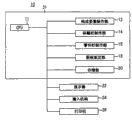
图1是本实施方式的CAD系统的块形构成图;Fig. 1 is a block diagram of the CAD system of the present embodiment;
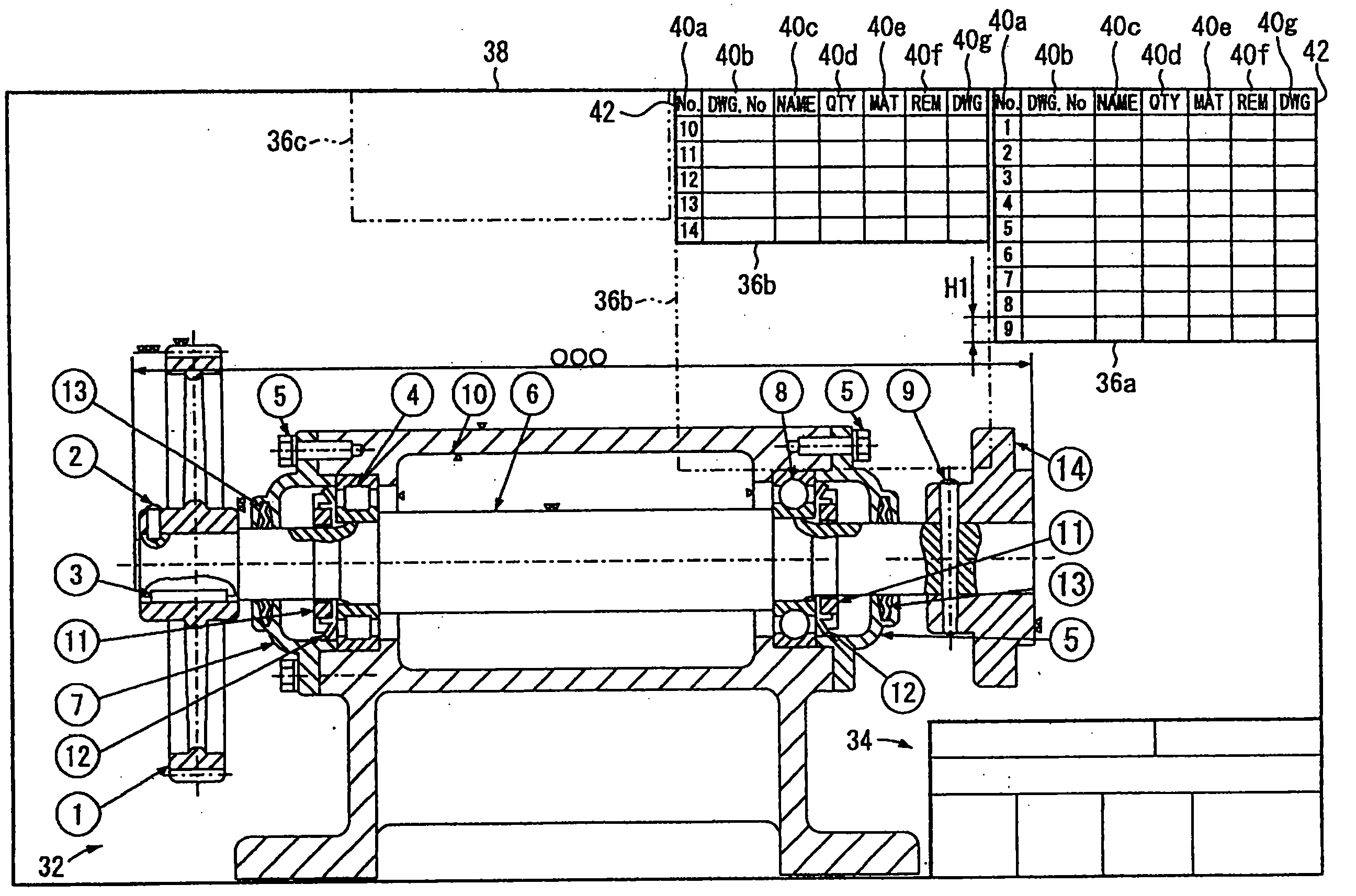
图2是通过CAD系统作成的机械设计图;Fig. 2 is the mechanical design diagram made by the CAD system;
图3是零件栏制作部的块形构成图;Figure 3 is a block diagram of the parts column production department;
图4是表示通过换行方向决定部显示在显示器的显示图像上的设定对话框的图;4 is a diagram showing a setting dialog box displayed on a display image of a display by a line feed direction determination unit;
图5是表示本实施方式的零件制作方法的顺序的流程图(其1);FIG. 5 is a flow chart (Part 1) showing the procedure of the part manufacturing method of the present embodiment;
图6是表示本实施方式的零件制作方法的顺序的流程图(其2);Fig. 6 is a flow chart (part 2) showing the procedure of the part manufacturing method of the present embodiment;
图7是零件栏的高度被压缩后的机械设计图;Fig. 7 is a mechanical design diagram after the height of the parts column is compressed;
图8是零件栏被换行后的机械设计图;Fig. 8 is the mechanical design diagram after the parts column is changed;
图9是将零件栏向指定的左方向进行一次换行后,再次向右方向进行换行的机械设计图。Fig. 9 is a mechanical design diagram in which the parts column is changed to the designated left direction once, and then changed to the right direction again.
符号说明Symbol Description
10 CAD系统10 CAD system
16 零件栏制作部16 Parts Column Production Department
30 设计图30 design drawings
32 形状要素32 shape elements
34 标题栏34 title bar
36 零件栏36 Parts column
36a 分支前零件栏36a Parts column before branch
36b、36c分支出的零件栏36b, 36c branch out of the parts bar
38 图框38 frame
50 检测机构50 testing agencies
52 栏压缩机构52 column compression mechanism
54 段数检测机构54 segment detection mechanism
56 换行机构56 line break mechanism
58 换行方向决定部58 Determining the line feed direction
60 设定对话框60 Settings dialog
60a 零件行数输入部60a Part row number input section
60c 左换行按钮60c left line feed button
60d 右换行按扭60d Right line feed button
60e 换行的行显示部60e Line display for newline
具体实施方式Detailed ways
本发明的零件栏制作装置作为使用计算机制作设计图的CAD系统10而显示。另外,本发明的零件栏制作方法使用CAD系统10而实施。下面,参照附图1~图9,对本实施例的CAD系统10及零件栏制作方法举实施例进行说明。The parts column creating device of the present invention is displayed as a
如图1所示,CAD系统10具有:进行系统整体的总体控制的CPU11、形状要素制作部12、标题栏制作部14、零件栏制作部16、图框规定部18、保存作成的CAD数据的存储部20、根据该CAD数据表示设计图的显示器22、操作者操作的输入机构24、根据CAD数据打印设计图的打印机26,根据自输入机构24的操作,例如制作图2所示的设计图30的CAD数据。As shown in FIG. 1 , the
CPU11、形状要素制作部12、标题栏制作部14、零件栏制作部16、图框规定部18及存储部20设置于计算机主体31内。其中,CPU11及存储部20是硬件构成部,其他各制作部是通过CPU11读入程序并实施而实现的软件功能部。作为输入机构24,例如可举出键盘、鼠标及图形要素输入板等指示机构。The
图2是表示在通过形状要素制作部12制作的形状要素32、通过标题栏制作部14制作的标题栏34、通过零件栏制作部16制作的零件栏36及通过图框规定部18规定的图框38被设定在初始状态下,变更零件栏36前的状态的设计图30。FIG. 2 is a diagram showing a
图框38表示设计图30的外框,其他全部要素基本上被显示在图框38的内侧。形状要素32表示制作品,例如,在机械设计图的情况下,包括规定比例尺的三视图及其尺寸线、加工符号等。标题栏34是一次全部显示设计图名称、整理号码、盖章栏、制图者姓名、制图年月日、比例尺等目录事项的栏,且设置于图框38内的右下部分。The
零件栏36是对应于该构成零件且用多个栏表示形状要素的多个构成零件的规格的栏,例如从图框38内的右上部向下多行设置。零件栏36例如具有对应零件的记号栏40a、零件图号栏40b、零件名称栏40c、零件个数栏40d、零件的材料栏40e、备注事项栏40f及用于确认设计图的有无的栏40g。另外,零件栏36的最上一行是标题42,第二行以下为表示对应于各零件的信息的栏。第二行以下的栏按记号栏40a的顺序排列。在图2所示的例子中,对应于构成形状要素32的14种零件设有14行。零件栏36在表示由多个构成零件构成的机械中的组装图时尤其有用。另外,在表示包含多个电气零件的电气电路时也有用。The
如图3所示,零件栏制作部16具有:零件栏36的初始设定部48;检测零件栏36和形状要素32的重叠的检测机构50;当通过该重叠检测机构50检测出重叠时将各行的高度缩小的栏压缩机构52。初始设定部48对应于形状要素32的数量进行初始设定,且将零件栏36初始设在系统默认位置(例如图2所示从图框38的右上部向下排列的位置)。As shown in FIG. 3 , the parts
零件制作部16还具有:即使在通过该栏压缩机构52将零件栏36的各行的高度缩小到规定高度仍然产生重叠时,求出零件栏36的多行中和形状要素32重叠的行数的重叠行数检测机构54;使通过该行数检测机构54求出的重叠行数部分向和形状要素32不重叠的方向移动(下面叫做换行。)的换行机构56;根据自输入机构24得到的信息决定由换行机构56进行的换行方向的换行方向决定部58。The
换行方向决定部58在显示器22的显示图像上显示图4所示的设定对话框60,并基于来自操作者输入机构24的操作输入信息。The line feed
如图4所示,设定对话框60具有:零件行数输入部60a;通过点击操作可增减该零件行数输入部60a的值的微调按钮60b;左换行按钮60c;右换行按钮60d;表示换行的行数的换行栏表示部60e、增减该换行栏表示部60e的值的微调按钮60f。As shown in Figure 4, the setting
零件行数输入部60a及微调按钮60b是初始输入设定零件栏36的行数的部分。左换行按钮60c及右换行按钮60d是用于指定换行机构56产生的换行方向的按钮,通过点击操作左换行按钮60c而指定向左方向的换行,通过点击右换行按钮60d而指定向右方向的换行。还有,在设定对话框60中,没有指定向上下方向换行的按钮,而零件栏36通常是以标题42为基准在上下方向排列,因此,换行方向在左右任一方足够,这是容易理解的。在换行栏表示部60e及微调按钮60f,能够将自动求出的换行行数按照操作者的要求增减修正。The part row
设定对话框60还具有:选择性设定零件栏的种类的零件栏设定部60g、输入零件栏36各栏的信息的详细编辑部60h、适用编辑结果的Apply按钮60i、适用编辑结果且终止设定的OK按钮60J、不适用编辑结果而终止设定的Cancel按钮60k。The setting
参照图5及图6对使用如下构成的CAD系统10进行的零件栏制作方法进行说明。下面的说明中,只要没有预先通知就按照记载的步骤号顺序执行处理。另外,在制作的设计图上,零件栏36以外的图框38、形状要素32及标题栏34,也可以根据图框规定部18、形状要素制作部12及标题栏制作部14预先制作。A method of creating a parts column using the
在图5的步骤S1,根据操作者的规定操作表示对话框60,且将零件栏36的行数输入零件行数输入部60a。在零件行数输入部60a,起初,也可以临时设定0以外的适当的默认值,或也可以自动地检测出构成形状要素32的零件的种类临时设定对应该种类的数字。在这种情况下,只要在没有实施输入操作时将临时设定用作其正式设定值即可。零件行数输入部60a的输入也可以用键盘的10个数字键直接输入数字,也可以通过微调按钮60b增减而输入。In step S1 of FIG. 5 , the
在步骤S2中,通过输入机构24的规定操作设定零件栏36的基准位置。In step S2 , the reference position of the
在步骤S3中,在初始设定部48的作用下,根据通过零件行数输入部60a及输入机构24的操作而设定的信息临时设定零件栏36,并临时表示在显示器22上(参照图2)。In step S3, under the action of the
在步骤S4中,在检测机构50的作用下,检测零件栏36和形状要素32的重叠的有无。该重叠的检测通过规定的坐标运算而执行。在被检测出有重叠的情况下向步骤S5转移,在没有被检测出重叠的情况下将临时表示作为正式表示而设定(步骤S16),并在CAD数据上进行登录且终止图5及图6表示的处理。In step S4 , by the
在步骤S5中,在栏压缩机构52的作用下,缩小零件栏36的标题42及各行的高度。即,将标题42及各栏的初始高度H0(参照图2)缩小为更低的高度H1(参照图7)。高度H1作为零件栏36内的文字可识别程度的低的高度被预先设定。In step S5 , under the action of the
在步骤S6中,和步骤S5相同,在检测机构50的作用下,检测零件栏36和形状要素32的重叠的有无。在检测出有重叠的情况下向步骤S7转移,在没有检测出有重叠的情况下执行步骤S6的处理后,终止图5及图6表示的处理。In step S6 , similarly to step S5 , the
执行步骤S5中的压缩处理时,也可以阶段性地执行步骤S6中的重叠检测处理。即,也可以不是将初始高度H0一次缩小到高度H1,而是每次压缩微小的宽度,且在变成没有重叠时向步骤S16转移,在被压缩到高度H1也没有消除重叠时再向步骤S7转移。When the compression processing in step S5 is performed, the overlapping detection processing in step S6 may also be performed in stages. That is, instead of shrinking the initial height H0 to the height H1 at one time, it is possible to compress a small width each time, and transfer to step S16 when there is no overlap, and then go to step S16 when the overlap is not eliminated after being compressed to the height H1 S7 transfer.
在步骤S16中,正式采用没有进行换行而在其时点得到的零件栏36,在CAD数据上进行登录并终止图5及图6表示的处理。In step S16, the
另一方面,在步骤S7中,通过点击操作左换行按钮60c或右换行按钮60d的任一个,指定使重叠的部分换行的方向。在根据零件栏36的基准位置一义决定换行方向的情况下,也可以省略步骤S7的处理,或决定对指定无关的换行方向。例如,如图2所示,也可以决定为:在零件栏36设在图框38内的右上部的情况下,由于在其右方向不能换行,因此,自动地向左方向换行。On the other hand, in step S7, by clicking either the left
在步骤S8中,在行数检测机构54的作用下,通过规定的坐标运算求出零件栏36的多行中和形状要素32重叠的行数。在图7所示的情况下,求出下栏的10~14栏的合计四栏重叠着的情况。In step S8, the number of rows overlapping with the
在步骤S9中,确认通过行数检测机构54求出的有重叠的行数是否是“1”以上。在重叠的行数是“1”以上的情况下向步骤S10转移,是“0”的情况下向步骤S12转移。In step S9, it is checked whether or not the number of overlapping rows obtained by the row
在步骤S10中,确认是否可以按照在步骤S7被指定的换行方向换行。即,确认仅零件栏36的宽W(参照图7)的宽是否已确保自该零件栏36的换行方向端部到图框38。例如,在使零件栏36向左方向换行的情况下零件栏36设在右端时,如图7所示,因为已确保自换行方向端部到图框38足够的宽W1(>W),因此,能够换行且向步骤S11转移。另一方面,因不能向右方向换行而向步骤S13转移。In step S10, it is confirmed whether the line feed can be performed in the line feed direction specified in step S7. That is, it is checked whether only the width W (see FIG. 7 ) of the
在步骤S11中,通过行数检测机构54求出的有重叠的行数部分向指定方向换行。即,如图8所示,原来状态的零件栏36中有重叠的下四行向指定方向(例如左方向)移动,原来状态的第10~第14行以与第1行~第4行的左侧邻接的方式进行移动。另外,标题42就此复写于其左侧。换行后和换行前的上端部重叠是为了操作者易于看到。In step S11, the number of overlapped lines obtained by the number of
将这样换行且被移动的零件栏作为分支出的零件栏36b,将不换行而剩余的部分称作分支前零件栏36a以进行区别。分支前零件栏36a和分支出的零件栏36b之间稍稍离开以明确区别,或也可以用另外的格线所谓不同的线(例如,粗线及双重线等)表示。In this way, the parts column that has been changed and moved is referred to as a
在进行换行后,分支前零件栏36a被确定,之后,以分支出的零件栏36变为处理对象继续进行向步骤S8的返回的处理。After the line feed is performed, the
即,相对于分支前零件栏36a进一步调查和形状要素32的重叠的有无,在有重叠的情况下进行进一步的分支而得到分支出的零件栏36c(参照图8的假想线)。另外,在没有重叠的情况下,从步骤S9向步骤S12转移,至此,将换行而得到的分支出的零件栏36b、36c...在CAD数据上进行登录,终止图5及图6所示的处理。That is, the presence or absence of overlap with the
另一方面,在步骤S13中,确认相对于在步骤S7中被指定的方向是否可以向相反方向换行。即,确认在与指定方向相反侧到图框38之间是否已确保宽W。在能够向相反方向换行的情况下向步骤S14转移,在不能换行的情况下向步骤S15转移。On the other hand, in step S13, it is checked whether or not a line feed can be performed in the opposite direction with respect to the direction specified in step S7. That is, it is checked whether or not the width W is secured between the
在步骤S14中,向和指定方向相反的方向进行换行。该步骤S14的处理和所述的步骤S11的处理除换行方向是相反的以外其余是相同的处理。步骤S14处理之后返回步骤S8。In step S14, line feed is performed in the direction opposite to the designated direction. The processing of this step S14 is the same processing as the processing of the above-mentioned step S11 except that the line feed direction is reversed. Return to step S8 after processing in step S14.
这样,通过进行相反方向的换行,例如,如图9所示,在向指定的方向进行一次换行之后还产生重叠部分的情况下,即使不能按以上向左方向换行,如果在右方向有空白,则进行换行,就会成为分支前零件栏36a及两个分支出的零件栏36b、36c的任一个与形状要素32没有重叠的表示。In this way, by performing line breaks in the opposite direction, for example, as shown in Figure 9, in the case of overlapping parts after performing line breaks in the specified direction once, even if the line breaks cannot be done in the left direction as above, if there is a blank space in the right direction, If the line is changed, the
在步骤S15中,就此确定在此时点得到的分支出的零件栏36b、36c...,在CAD数据上进行登录并终止图5及图6所示的处理。In step S15, the branched
应当被记载于零件栏36、分支前零件栏36a、分支出的零件栏36b、36c...的信息可以在如前所述的详细编辑部60h进行编辑。由详细编辑部60h进行的编辑也可以在初始设定零件栏36时执行,也可以在终止一连串换行处理之后执行。The information to be written in the
另外,也可以是操作者对零件栏36换行的结果在显示器22的显示图像上进行确认,并考虑要求及布局的均衡而操作换行栏表示部60e(参照图4)调整换行的行数。In addition, the operator may confirm the result of the line break of the
如上所述,根据本实施方式的CAD系统10及零件栏制作方法,在检测出有形状要素32和零件栏36的重叠的情况下,通过使重叠的行数部分从其另外的不重叠的部分分离并移动(换行),能够自动且适当地消除零件栏36和形状要素32的重叠。因而,即使在没有使形状要素32上下左右移动的空白余量的情况下,也能够缩小形状要素32,且不需要将整个设计图设定变更为1号大的用纸规格,从而能够有效地利用空白明确地显示形状要素32及零件栏36两者。As described above, according to the
另外,通过点击操作左换行按钮60c或换行按钮60d能够指定换行方向,因此,成为能够根据操作者的要求的版式设计的设定,版式设计的自由度提高。In addition, since the line feed direction can be specified by clicking and operating the left
此外,起初,即使是产生重叠的情况,因为能够在栏压缩机构52的作用下将零件栏36的各行的高度缩小,因此,能够抑制版式设计的变更,并尽量维持相同的版式设计。In addition, even if overlapping occurs initially, since the height of each row of the
另外,在上述中,对形状要素32相对于零件栏36产生自最下栏测(即,第14栏侧)延伸的重叠的情况进行了说明,但零件栏36和形状要素32的重叠方位不限于此,例如,形状要素32自左侧方延伸只在零件栏36的中间栏部重叠的情况,也能够按照和上述同样的顺序将重叠消除。当然,形状要素32是表示三维形状数据的形状要素(所谓3D-CAD)也可以。In addition, in the above, the case where the
本发明的零件栏制作装置及零件栏制作方法不限于上述的实施方式,不言而喻,只要不脱离本发明的宗旨,采用各种各样的构成而得到都可以。The parts column creation apparatus and the parts column creation method of this invention are not limited to the above-mentioned embodiment, Needless to say, as long as it does not deviate from the gist of this invention, it can employ|adopt various structures and obtain it.
Claims (3)
Applications Claiming Priority (3)
| Application Number | Priority Date | Filing Date | Title |
|---|---|---|---|
| JP2006-096508 | 2006-03-31 | ||
| JP2006096508A JP4681486B2 (en) | 2006-03-31 | 2006-03-31 | Parts field creation device and parts field creation method |
| JP2006096508 | 2006-03-31 |
Publications (2)
| Publication Number | Publication Date |
|---|---|
| CN101046830A CN101046830A (en) | 2007-10-03 |
| CN101046830B true CN101046830B (en) | 2010-05-26 |
Family
ID=38558207
Family Applications (1)
| Application Number | Title | Priority Date | Filing Date |
|---|---|---|---|
| CN2007100887782A Expired - Fee Related CN101046830B (en) | 2006-03-31 | 2007-03-22 | Device for making part column and method for making part column |
Country Status (4)
| Country | Link |
|---|---|
| US (1) | US8015503B2 (en) |
| JP (1) | JP4681486B2 (en) |
| CN (1) | CN101046830B (en) |
| BR (1) | BRPI0701349A2 (en) |
Families Citing this family (2)
| Publication number | Priority date | Publication date | Assignee | Title |
|---|---|---|---|---|
| CN102945313A (en) * | 2012-10-18 | 2013-02-27 | 北京航空航天大学 | Method for constructing and demonstrating teaching content of open type virtual experiment |
| CN112613130B (en) * | 2021-03-05 | 2021-07-02 | 成都飞机工业(集团)有限责任公司 | Dimensional positioning pose simulation matching method based on two three-coordinate positioners |
Citations (1)
| Publication number | Priority date | Publication date | Assignee | Title |
|---|---|---|---|---|
| US5943243A (en) * | 1996-10-28 | 1999-08-24 | International Business Machines Corporation | Method and system for removing hardware design overlap |
Family Cites Families (18)
| Publication number | Priority date | Publication date | Assignee | Title |
|---|---|---|---|---|
| EP0548240A1 (en) * | 1990-09-10 | 1993-06-30 | Lotus Development Corporation | Apparatus and method for reformattable spreadsheet |
| JPH07182397A (en) | 1993-12-22 | 1995-07-21 | Pfu Ltd | Drawing method and drawing apparatus |
| JPH08221589A (en) * | 1995-02-16 | 1996-08-30 | Matsushita Electric Ind Co Ltd | Graphic frame creating apparatus and graphic frame creating method |
| US5737558A (en) * | 1995-08-08 | 1998-04-07 | International Business Machines Corporation | Multi-column windows |
| US5838318A (en) * | 1995-11-10 | 1998-11-17 | Intel Corporation | Method and apparatus for automatically and intelligently arranging windows on a display device |
| JP3396404B2 (en) * | 1996-09-24 | 2003-04-14 | 富士通株式会社 | Automatic string editing system |
| JPH10240781A (en) * | 1997-02-21 | 1998-09-11 | Nissan Motor Co Ltd | CAD drawing size changing device |
| JPH10240324A (en) * | 1997-02-27 | 1998-09-11 | Toshiba Corp | Assembly sequence extraction method and apparatus |
| JPH11185046A (en) * | 1997-12-18 | 1999-07-09 | Canon Inc | Graphic editing apparatus, layout processing method, and storage medium |
| FR2793941B1 (en) | 1999-05-17 | 2001-08-03 | Hutchinson | ELECTROMAGNETIC ACTUATOR |
| US7028264B2 (en) * | 1999-10-29 | 2006-04-11 | Surfcast, Inc. | System and method for simultaneous display of multiple information sources |
| JP3884901B2 (en) * | 2000-07-19 | 2007-02-21 | 東京電力株式会社 | Data arrangement method and two-dimensional drawing data processing system |
| JP2003150648A (en) * | 2001-11-14 | 2003-05-23 | Mitsubishi Heavy Ind Ltd | Component column preparation method |
| JP2003281197A (en) * | 2002-03-25 | 2003-10-03 | Honda Motor Co Ltd | Electronic parts list system |
| JP2003281198A (en) * | 2002-03-25 | 2003-10-03 | Honda Motor Co Ltd | Electronic parts list system and electronic parts list creation method |
| US7366978B1 (en) * | 2003-02-13 | 2008-04-29 | Microsoft Corporation | Method and system for creating a grid-like coordinate system for addressing data contained in an irregular computer-generated table |
| US7554689B2 (en) * | 2003-10-15 | 2009-06-30 | Canon Kabushiki Kaisha | Document layout method |
| JP4107668B2 (en) * | 2004-10-07 | 2008-06-25 | インターナショナル・ビジネス・マシーンズ・コーポレーション | Editing apparatus, editing method, and program |
-
2006
- 2006-03-31 JP JP2006096508A patent/JP4681486B2/en not_active Expired - Fee Related
-
2007
- 2007-03-22 CN CN2007100887782A patent/CN101046830B/en not_active Expired - Fee Related
- 2007-03-28 US US11/727,790 patent/US8015503B2/en not_active Expired - Fee Related
- 2007-03-29 BR BRPI0701349-3A patent/BRPI0701349A2/en active Search and Examination
Patent Citations (1)
| Publication number | Priority date | Publication date | Assignee | Title |
|---|---|---|---|---|
| US5943243A (en) * | 1996-10-28 | 1999-08-24 | International Business Machines Corporation | Method and system for removing hardware design overlap |
Non-Patent Citations (2)
| Title |
|---|
| JP特開2001-84281A 2001.03.30 |
| JP特開平7-182397A 1995.07.21 |
Also Published As
| Publication number | Publication date |
|---|---|
| US20070229551A1 (en) | 2007-10-04 |
| CN101046830A (en) | 2007-10-03 |
| JP2007272509A (en) | 2007-10-18 |
| BRPI0701349A2 (en) | 2008-11-11 |
| US8015503B2 (en) | 2011-09-06 |
| JP4681486B2 (en) | 2011-05-11 |
Similar Documents
| Publication | Publication Date | Title |
|---|---|---|
| CN102141879B (en) | Information processing apparatus and information processing method | |
| CN101046830B (en) | Device for making part column and method for making part column | |
| JP2010026627A (en) | Programmable display device | |
| KR101601691B1 (en) | Method and apparatus for using a layer on an electronic document | |
| JP5061636B2 (en) | Information processing apparatus, information processing system, and program | |
| JP4696612B2 (en) | Display control apparatus and display screen reduction method | |
| JP4992399B2 (en) | Document editing apparatus and program | |
| JP5028980B2 (en) | Document editing apparatus and program | |
| KR20160024105A (en) | Page turning method of electronic book for touch screen | |
| JP4325712B2 (en) | Inequality calculator | |
| JP2013182419A (en) | Image layout system, image editor device, and page layout device | |
| JP2644479B2 (en) | Document creation device | |
| JP2004013514A (en) | Data display device and data display method | |
| JP2024092901A (en) | Inspection information recording system | |
| JPS63269266A (en) | character recognition device | |
| JPH0731671B2 (en) | Formula input editing method | |
| JPH0863610A (en) | Document processing device | |
| US20110099469A1 (en) | Information processing apparatus, control method, and storage medium | |
| JP2024033745A (en) | Control method and program | |
| JP5223546B2 (en) | Image processing apparatus and program | |
| JP2763836B2 (en) | Sentence processing device and method for changing format of sentence processing device | |
| JP2007047947A (en) | 3D shape processing method, 3D shape processing apparatus, program, and storage medium | |
| JPH03161861A (en) | Document processing device with table creation function | |
| JP2007073000A (en) | Print processing method, print processing apparatus, print processing program, and storage medium | |
| JPS61105591A (en) | Editing unit |
Legal Events
| Date | Code | Title | Description |
|---|---|---|---|
| C06 | Publication | ||
| PB01 | Publication | ||
| C10 | Entry into substantive examination | ||
| SE01 | Entry into force of request for substantive examination | ||
| C14 | Grant of patent or utility model | ||
| GR01 | Patent grant | ||
| CF01 | Termination of patent right due to non-payment of annual fee | ||
| CF01 | Termination of patent right due to non-payment of annual fee |
Granted publication date: 20100526 Termination date: 20200322 |