CN101122425A - A silicon carbide foam ceramic solar air heat absorber - Google Patents
A silicon carbide foam ceramic solar air heat absorber Download PDFInfo
- Publication number
- CN101122425A CN101122425A CNA2007100990393A CN200710099039A CN101122425A CN 101122425 A CN101122425 A CN 101122425A CN A2007100990393 A CNA2007100990393 A CN A2007100990393A CN 200710099039 A CN200710099039 A CN 200710099039A CN 101122425 A CN101122425 A CN 101122425A
- Authority
- CN
- China
- Prior art keywords
- silicon carbide
- air
- carbide foam
- foam ceramic
- heat
- Prior art date
- Legal status (The legal status is an assumption and is not a legal conclusion. Google has not performed a legal analysis and makes no representation as to the accuracy of the status listed.)
- Granted
Links
- 239000000919 ceramic Substances 0.000 title claims abstract description 102
- HBMJWWWQQXIZIP-UHFFFAOYSA-N silicon carbide Chemical compound [Si+]#[C-] HBMJWWWQQXIZIP-UHFFFAOYSA-N 0.000 title claims abstract description 98
- 229910010271 silicon carbide Inorganic materials 0.000 title claims abstract description 98
- 239000006260 foam Substances 0.000 title claims abstract description 97
- 239000006096 absorbing agent Substances 0.000 title claims abstract description 84
- 230000005855 radiation Effects 0.000 claims abstract description 44
- VYPSYNLAJGMNEJ-UHFFFAOYSA-N Silicium dioxide Chemical compound O=[Si]=O VYPSYNLAJGMNEJ-UHFFFAOYSA-N 0.000 claims abstract description 13
- 238000009413 insulation Methods 0.000 claims abstract description 12
- 229910010293 ceramic material Inorganic materials 0.000 claims abstract description 5
- 238000012546 transfer Methods 0.000 abstract description 17
- 238000005338 heat storage Methods 0.000 abstract description 7
- 239000011148 porous material Substances 0.000 description 18
- 238000000034 method Methods 0.000 description 15
- 238000010521 absorption reaction Methods 0.000 description 6
- 238000009826 distribution Methods 0.000 description 6
- 239000000463 material Substances 0.000 description 6
- 238000013461 design Methods 0.000 description 5
- 239000000126 substance Substances 0.000 description 5
- 230000007423 decrease Effects 0.000 description 4
- 238000010586 diagram Methods 0.000 description 4
- 239000012530 fluid Substances 0.000 description 4
- 229910052751 metal Inorganic materials 0.000 description 4
- 239000002184 metal Substances 0.000 description 4
- 238000010248 power generation Methods 0.000 description 4
- 230000007774 longterm Effects 0.000 description 3
- 238000007789 sealing Methods 0.000 description 3
- 238000000576 coating method Methods 0.000 description 2
- 239000011521 glass Substances 0.000 description 2
- VYZAMTAEIAYCRO-UHFFFAOYSA-N Chromium Chemical compound [Cr] VYZAMTAEIAYCRO-UHFFFAOYSA-N 0.000 description 1
- DGAQECJNVWCQMB-PUAWFVPOSA-M Ilexoside XXIX Chemical compound C[C@@H]1CC[C@@]2(CC[C@@]3(C(=CC[C@H]4[C@]3(CC[C@@H]5[C@@]4(CC[C@@H](C5(C)C)OS(=O)(=O)[O-])C)C)[C@@H]2[C@]1(C)O)C)C(=O)O[C@H]6[C@@H]([C@H]([C@@H]([C@H](O6)CO)O)O)O.[Na+] DGAQECJNVWCQMB-PUAWFVPOSA-M 0.000 description 1
- 238000006243 chemical reaction Methods 0.000 description 1
- 229910052804 chromium Inorganic materials 0.000 description 1
- 239000011651 chromium Substances 0.000 description 1
- 239000011248 coating agent Substances 0.000 description 1
- 230000002860 competitive effect Effects 0.000 description 1
- 239000008358 core component Substances 0.000 description 1
- 230000003247 decreasing effect Effects 0.000 description 1
- 238000011161 development Methods 0.000 description 1
- 230000005611 electricity Effects 0.000 description 1
- 238000005516 engineering process Methods 0.000 description 1
- 239000002803 fossil fuel Substances 0.000 description 1
- 239000013529 heat transfer fluid Substances 0.000 description 1
- 238000010438 heat treatment Methods 0.000 description 1
- 239000011159 matrix material Substances 0.000 description 1
- 229910001092 metal group alloy Inorganic materials 0.000 description 1
- 229910044991 metal oxide Inorganic materials 0.000 description 1
- 150000004706 metal oxides Chemical class 0.000 description 1
- 150000002739 metals Chemical class 0.000 description 1
- 238000013021 overheating Methods 0.000 description 1
- 239000002245 particle Substances 0.000 description 1
- 239000012782 phase change material Substances 0.000 description 1
- 230000001737 promoting effect Effects 0.000 description 1
- 238000011160 research Methods 0.000 description 1
- 229910052708 sodium Inorganic materials 0.000 description 1
- 239000011734 sodium Substances 0.000 description 1
- 239000010935 stainless steel Substances 0.000 description 1
- 229910001220 stainless steel Inorganic materials 0.000 description 1
- 229910052715 tantalum Inorganic materials 0.000 description 1
- GUVRBAGPIYLISA-UHFFFAOYSA-N tantalum atom Chemical compound [Ta] GUVRBAGPIYLISA-UHFFFAOYSA-N 0.000 description 1
- WFKWXMTUELFFGS-UHFFFAOYSA-N tungsten Chemical compound [W] WFKWXMTUELFFGS-UHFFFAOYSA-N 0.000 description 1
- 229910052721 tungsten Inorganic materials 0.000 description 1
- 239000010937 tungsten Substances 0.000 description 1
- 238000009827 uniform distribution Methods 0.000 description 1
Images


Classifications
-
- F—MECHANICAL ENGINEERING; LIGHTING; HEATING; WEAPONS; BLASTING
- F24—HEATING; RANGES; VENTILATING
- F24S—SOLAR HEAT COLLECTORS; SOLAR HEAT SYSTEMS
- F24S20/00—Solar heat collectors specially adapted for particular uses or environments
- F24S20/20—Solar heat collectors for receiving concentrated solar energy, e.g. receivers for solar power plants
-
- F—MECHANICAL ENGINEERING; LIGHTING; HEATING; WEAPONS; BLASTING
- F24—HEATING; RANGES; VENTILATING
- F24S—SOLAR HEAT COLLECTORS; SOLAR HEAT SYSTEMS
- F24S10/00—Solar heat collectors using working fluids
- F24S10/80—Solar heat collectors using working fluids comprising porous material or permeable masses directly contacting the working fluids
-
- F—MECHANICAL ENGINEERING; LIGHTING; HEATING; WEAPONS; BLASTING
- F24—HEATING; RANGES; VENTILATING
- F24S—SOLAR HEAT COLLECTORS; SOLAR HEAT SYSTEMS
- F24S80/00—Details, accessories or component parts of solar heat collectors not provided for in groups F24S10/00-F24S70/00
- F24S2080/01—Selection of particular materials
- F24S2080/013—Foams
-
- Y—GENERAL TAGGING OF NEW TECHNOLOGICAL DEVELOPMENTS; GENERAL TAGGING OF CROSS-SECTIONAL TECHNOLOGIES SPANNING OVER SEVERAL SECTIONS OF THE IPC; TECHNICAL SUBJECTS COVERED BY FORMER USPC CROSS-REFERENCE ART COLLECTIONS [XRACs] AND DIGESTS
- Y02—TECHNOLOGIES OR APPLICATIONS FOR MITIGATION OR ADAPTATION AGAINST CLIMATE CHANGE
- Y02E—REDUCTION OF GREENHOUSE GAS [GHG] EMISSIONS, RELATED TO ENERGY GENERATION, TRANSMISSION OR DISTRIBUTION
- Y02E10/00—Energy generation through renewable energy sources
- Y02E10/40—Solar thermal energy, e.g. solar towers
- Y02E10/44—Heat exchange systems
Landscapes
- Engineering & Computer Science (AREA)
- Chemical & Material Sciences (AREA)
- Sustainable Energy (AREA)
- Life Sciences & Earth Sciences (AREA)
- Physics & Mathematics (AREA)
- Sustainable Development (AREA)
- Thermal Sciences (AREA)
- Combustion & Propulsion (AREA)
- Mechanical Engineering (AREA)
- General Engineering & Computer Science (AREA)
- Dispersion Chemistry (AREA)
- Porous Artificial Stone Or Porous Ceramic Products (AREA)
- Heat-Exchange Devices With Radiators And Conduit Assemblies (AREA)
Abstract
一种碳化硅泡沫陶瓷太阳能空气吸热器,以碳化硅泡沫陶瓷材料作为太阳能吸收体。碳化硅泡沫陶瓷吸收体[1]外部包覆有保温层[2],辐射热流[3]投射到硅泡沫陶瓷吸收体[1]表面或投入人工黑体空腔[9],由碳化硅泡沫陶瓷接收体[1]接收,冷空气[4]直接从碳化硅泡沫陶瓷接收体[1]正对辐射热流[3]侧流入,经换热后获得热空气[5];或辐射热流[3]透过石英玻璃窗[10],冷空气[4]从碳化硅泡沫陶瓷接收体[1]正对辐射热流[3]侧或背对辐射热流[3]侧流入,经换热后获得700℃-1300℃的热空气[5],碳化硅泡沫陶瓷接收体[1]预埋空气导流通道[8]。本发明可高效接收辐射热和高效地向空气传热,同时利用自身的显热进行储热。
A silicon carbide foam ceramic solar air heat absorber uses silicon carbide foam ceramic material as a solar absorber. The silicon carbide foam ceramic absorber [1] is covered with an insulation layer [2], and the radiant heat flow [3] is projected onto the surface of the silicon carbide foam ceramic absorber [1] or put into an artificial blackbody cavity [9]. Received by the receiver [1], the cold air [4] flows directly from the silicon carbide foam ceramic receiver [1] facing the radiation heat flow [3] side, and the hot air [5] is obtained after heat exchange; or the radiation heat flow [3] Through the quartz glass window [10], cold air [4] flows in from the side facing the radiation heat flow [3] or the side facing away from the radiation heat flow [3] of the silicon carbide foam ceramic receiver [1], and obtains a temperature of 700 °C after heat exchange. -1300℃ hot air [5], silicon carbide foam ceramic receiver [1] pre-buried air diversion channel [8]. The invention can efficiently receive radiant heat and efficiently transfer heat to the air, while using its own sensible heat for heat storage.
Description
技术领域technical field
本发明涉及一种太阳能空气吸热器,特别涉及碳化硅泡沫陶瓷太阳能空气吸热器。The invention relates to a solar air heat absorber, in particular to a silicon carbide foam ceramic solar air heat absorber.
背景技术Background technique
太阳能是取之不尽用之不竭的可再生能源,在化石燃料逐年减少、国际能源形势日趋严峻的今天,开发利用太阳能是实现能源供应多元化、保证能源安全的重要途径之一。Solar energy is an inexhaustible renewable energy source. Today, as fossil fuels are decreasing year by year and the international energy situation is becoming increasingly severe, the development and utilization of solar energy is one of the important ways to realize the diversification of energy supply and ensure energy security.
迄今为止,已经有塔式、槽式、碟式等多种热发电方式,其中塔式热发电装置是最具竞争力的技术装置,其基本原理是利用众多的定日镜,将太阳辐射反射到置于塔上的太阳能接收器上,借助加热工质产生过热蒸汽或高温空气,驱动发电机组,产生电能。高温太阳能吸热器是塔式热发电系统的核心部件。国外围绕此项技术进行了诸多研究,主要集中在美国、西班牙、德国、以色列等,国内在该方面起步较晚,研究成果也较少。高温太阳能吸热器按结构类型大致可以分为两种形式:外部受光型和空腔型。其中应用较多的是容积式吸热器,就是一种由三维的基体所构成的太阳能吸热器,可使从中流过的工作流体与其进行直接的热交换。容积式太阳能吸热器通常有一个空心壳体,用于容纳容积式太阳能吸收装置,壳体由玻璃透光窗覆盖,形成封闭的吸热装置腔体,腔体可以容纳与吸收装置直接接触的工作流体,工作流体流过吸热装置腔体,从吸收装置上吸收热量。美国专利4394859公开了一种以空气为传热流体的柱状金属管式吸热器,该吸热器对金属要求较高,系统复杂,成本高。美国专利4777934公布了采用带有粒子的压缩空气为传热介质的太阳能吸热器,其温度可被加热至700℃,该吸热器无法应用到更高的温度。美国专利US6668555B1公布了基于吸热器的太阳能发电系统,采用热管式太阳能吸热器,其传热工质为空气,虽然传热效率较高,但应用于高温需要采用金属钠等物质作为热管内的相变材料,对安全性要求苛刻。美国专利4318393公布了采用包括不锈钢、铬、钽、钨等耐高温金属、金属合金或金属氧化物等多孔表面的太阳能吸热器,采用空气为传热工质,其温度可被加热到500℃~1500℃,但由于多孔表面的孔隙分布为圆柱形孔洞,如图1,多孔表面吸热体11的骨架12和孔隙13尺寸,图1中(a)图的A-A剖面如图(b),表明其吸热体11表面的孔隙13是柱状结构。该专利的不足之处为:(1)圆柱管内空气彼此不联通,当太阳投入辐射不均匀时,骨架12局部过热部分的热量仅靠直接接触的空气流动将无法快速带走表面吸收的辐射热,易造成骨架12的局部烧毁;(2)仅采用多孔表面吸热,在表面辐射投入不均匀时,由于空气的粘性随温度升高而成指数规律增长,流动阻力随温度增高而增大,其表面温度的非均匀变化使得空气流动不稳定,使得温度高的区域空气流量减少,而温度低的区域空气流量增大,吸热器的效率降低,传热过程恶化。中国专利CN2758657提出了腔式太阳能吸收器,但其结构较为复杂,分为内外两个腔,内腔体临近石英玻璃窗表面涂覆太阳能选择性吸收涂层,并且采用不同的物质用于传热和蓄热,用于高温情况。此专利给太阳能选择性吸收涂层提出了苛刻要求。中国专利CN2872208提出了一种空腔式太阳能吸收器,采用了针管冷却玻璃窗、管状吸热体,管状吸热体的换热表面积小,传热效率不高,并且采用不同材料作为吸热体与蓄热体,结构复杂。So far, there have been a variety of thermal power generation methods such as tower type, trough type, and dish type. Among them, the tower type thermal power generation device is the most competitive technical device. Its basic principle is to use many heliostats to reflect solar radiation. On the solar receiver placed on the tower, superheated steam or high-temperature air is generated by heating the working fluid, and the generator set is driven to generate electricity. The high temperature solar heat absorber is the core component of the tower thermal power generation system. Many studies have been carried out on this technology in foreign countries, mainly in the United States, Spain, Germany, Israel, etc. In China, this aspect started relatively late, and the research results are few. High-temperature solar heat absorbers can be roughly divided into two types according to the structure type: external light-receiving type and cavity type. Among them, the volumetric heat absorber is more widely used, which is a solar heat absorber composed of a three-dimensional matrix, which can directly exchange heat with the working fluid flowing through it. The volumetric solar heat absorber usually has a hollow shell for containing the volumetric solar absorbing device, and the shell is covered by a glass light-transmitting window to form a closed heat absorbing device cavity, which can accommodate the direct contact with the absorbing device. Working fluid, the working fluid flows through the cavity of the heat absorbing device and absorbs heat from the absorbing device. US Patent No. 4,394,859 discloses a cylindrical metal tube heat absorber using air as the heat transfer fluid. The heat absorber has high requirements on metal, complicated system and high cost. US Patent No. 4,777,934 discloses a solar heat absorber that uses compressed air with particles as a heat transfer medium, and its temperature can be heated to 700° C., but the heat absorber cannot be applied to higher temperatures. U.S. Patent US6668555B1 discloses a solar power generation system based on a heat absorber. A heat pipe solar heat absorber is used. The heat transfer medium is air. Although the heat transfer efficiency is high, it is necessary to use metal sodium and other substances as the heat pipe for high temperature applications. phase change materials, which have strict requirements on safety. U.S. Patent No. 4,318,393 discloses a solar heat absorber that uses porous surfaces such as stainless steel, chromium, tantalum, tungsten and other high-temperature-resistant metals, metal alloys, or metal oxides. Air is used as the heat transfer medium, and its temperature can be heated to 500 ° C. ~1500°C, but because the pores on the porous surface are distributed as cylindrical holes, as shown in Figure 1, the size of the
发明内容Contents of the invention
本发明的目的是克服现有技术结构复杂、高温使用受限及空气流动稳定性欠佳的缺点,提供一种碳化硅泡沫陶瓷太阳能空气吸热器,采用碳化硅泡沫陶瓷材料作为太阳能吸收体,该吸收体预埋有空气导流通道,同时利用了碳化硅泡沫陶瓷自身三维多孔结构、吸收率高、耐高温、高导热的特点,兼有储热功能。The purpose of the present invention is to overcome the disadvantages of complex structure, limited high temperature use and poor air flow stability in the prior art, and provide a silicon carbide foam ceramic solar air heat absorber, which uses silicon carbide foam ceramic material as a solar absorber, The absorber is pre-embedded with air guide channels, and at the same time, it utilizes the characteristics of silicon carbide foam ceramics' three-dimensional porous structure, high absorption rate, high temperature resistance, and high thermal conductivity, and also has the function of heat storage.
鉴于太阳能投入辐射的不均匀特点,在碳化硅泡沫陶瓷吸热体内预埋空气导流通道,空气导流通道位于靠近吸收太阳投入辐射侧或者高温空气出口侧,使得具有较高温度空气能够顺畅的流入空气温度较低区域,达到均匀空气温度的、稳定空气流场的目的。空气导流通道的结构采用斜圆柱孔、直圆柱孔或者二者的组合,其尺寸和孔结构的选择由空气流场参数和投入辐射的分布情况决定,其原则是既做到不同温度的空气充分混合又能系统空气流动阻力最小。In view of the unevenness of solar input radiation, the air guide channel is embedded in the silicon carbide foam ceramic heat absorber. The air guide channel is located close to the side that absorbs the solar input radiation or the high-temperature air outlet side, so that the air with higher temperature can flow smoothly. It flows into the area with low air temperature to achieve the purpose of uniform air temperature and stable air flow field. The structure of the air guide channel adopts oblique cylindrical holes, straight cylindrical holes or a combination of the two. The selection of its size and hole structure is determined by the parameters of the air flow field and the distribution of input radiation. Thorough mixing and minimal resistance to system air flow.
碳化硅泡沫陶瓷是具有三维空间网架结构的高气孔率的多孔陶瓷体,本发明的碳化硅泡沫陶瓷太阳能空气吸热器,采用碳化硅泡沫陶瓷材料作为太阳能吸收体,其内预埋有空气导流通道,空气为传热介质。经聚光设备收集的太阳辐射能投射到碳化硅泡沫陶瓷接收体上,由于碳化硅泡沫陶瓷的三维多孔特征,辐射能被碳化硅泡沫陶瓷表面吸收,穿过表面孔隙,被碳化硅泡沫陶瓷接收体内部的陶瓷骨架吸收,辐射能转化为碳化硅泡沫陶瓷的热能,使得吸收了辐射能的碳化硅泡沫陶瓷部分温度升高。碳化硅泡沫陶瓷具有很高的导热系数,热量迅速在陶瓷骨架间传导,使得整个碳化硅泡沫陶瓷接收体的温度升高。通过风机将冷空气引入碳化硅泡沫陶瓷接收体内,由于碳化硅泡沫陶瓷的多孔特性,空气与陶瓷骨架间有很大的接触面积,冷空气与热的碳化硅泡沫陶瓷表面间进行对流传热,吸收热量后温度升高。碳化硅泡沫陶瓷本身的热容量可以存储一定数量的吸收辐射热,用于没有投入辐射时加热空气。碳化硅泡沫陶瓷耐温超过1600℃,确保了本发明的空气吸热器可以用于较高的温度。碳化硅泡沫陶瓷骨架的导热系数大于100W/m/K,在太阳投入辐射不均时,局部吸热的形成高温可以通过骨架向四周迅速传导,同时,通过设计1-6mm的三维孔隙结构,结合预埋的空气导流通道,使得具有不同温度的空气能够充分混合,达到均匀温度的目的。温度均匀的空气在整个吸热体中流场稳定,可以降低流动阻力和提高吸热体的吸热效率,温度场的均匀分布,避免了局部的过热破坏,提高了吸热器的安全性。因此,本发明碳化硅泡沫陶瓷的三维孔隙结构、预埋的空气导流通道及骨架的高导热特征,保证了空气在高温情况下的均匀、稳定流动和吸热器的长期、高效、安全运行。Silicon carbide foam ceramics is a porous ceramic body with high porosity with a three-dimensional space grid structure. The silicon carbide foam ceramic solar air heat absorber of the present invention adopts silicon carbide foam ceramic materials as a solar absorber, and air is pre-embedded in it. Air guide channel, air is the heat transfer medium. The solar radiation energy collected by the concentrating equipment is projected onto the silicon carbide foam ceramic receiver. Due to the three-dimensional porous characteristics of the silicon carbide foam ceramics, the radiation energy is absorbed by the surface of the silicon carbide foam ceramics, passes through the surface pores, and is received by the silicon carbide foam ceramics. The ceramic skeleton inside the body absorbs, and the radiation energy is converted into heat energy of the silicon carbide foam ceramics, which makes the temperature of the silicon carbide foam ceramics part that absorbs the radiation energy rise. Silicon carbide foam ceramics has a high thermal conductivity, and the heat is quickly conducted between the ceramic skeletons, which makes the temperature of the entire silicon carbide foam ceramic receiver rise. The cold air is introduced into the silicon carbide foam ceramic receiver through the fan. Due to the porous characteristics of the silicon carbide foam ceramics, there is a large contact area between the air and the ceramic skeleton, and the convective heat transfer between the cold air and the hot silicon carbide foam ceramic surface, The temperature rises after absorbing heat. The heat capacity of silicon carbide foam ceramics can store a certain amount of absorbed radiant heat, which is used to heat the air when no radiation is input. The temperature resistance of silicon carbide foam ceramics exceeds 1600° C., which ensures that the air heat absorber of the present invention can be used at higher temperatures. The thermal conductivity of the silicon carbide foam ceramic skeleton is greater than 100W/m/K. When the sun's radiation is uneven, the high temperature formed by local heat absorption can be rapidly transmitted to the surroundings through the skeleton. At the same time, by designing a three-dimensional pore structure of 1-6mm, combined with The pre-buried air guide channel enables the air with different temperatures to be fully mixed to achieve the purpose of uniform temperature. The air with uniform temperature has a stable flow field in the entire heat absorber, which can reduce the flow resistance and improve the heat absorption efficiency of the heat absorber. The uniform distribution of the temperature field avoids local overheating damage and improves the safety of the heat absorber. Therefore, the three-dimensional pore structure of the silicon carbide foam ceramics of the present invention, the pre-buried air guide channel and the high thermal conductivity of the skeleton ensure the uniform and stable flow of air under high temperature conditions and the long-term, efficient and safe operation of the heat absorber .
本发明太阳能空气吸热器有外部受光方式和空腔方式。外部受光方式是将碳化硅泡沫陶瓷接收体直接置于汇聚的太阳光下进行吸热,冷空气从吸收体正对辐射侧流入,在流动过程中从吸收体获得热量,提升温度。该种方式冷空气侧不需要采取密封措施,结构简单。空腔方式是将碳化硅泡沫陶瓷制成一吸收辐射腔体,投入辐射经过石英玻璃窗后传入碳化硅泡沫陶瓷接收体内。根据空气的流动方式分为逆流和顺流两种,冷空气从吸收体正对辐射侧流入为顺流,冷空气从吸收体背对辐射侧流入为逆流。The solar air heat absorber of the present invention has an external light receiving mode and a cavity mode. The external light receiving method is to place the silicon carbide foam ceramic receiver directly under the concentrated sunlight to absorb heat. Cold air flows in from the absorber facing the radiation side, and heat is obtained from the absorber during the flow process to increase the temperature. In this way, no sealing measures are required on the cold air side, and the structure is simple. The cavity method is to make silicon carbide foam ceramics into a radiation-absorbing cavity, and the input radiation passes through the quartz glass window and then enters the silicon carbide foam ceramic receiver. According to the flow mode of the air, it can be divided into two types: countercurrent and downstream. The cold air flowing in from the side opposite to the radiation of the absorber is called downstream, and the cold air flowing in from the side of the absorber facing away from the radiation is called countercurrent.
碳化硅泡沫陶瓷接收体外侧覆有保温层,既能减少热损失,又可发挥密封作用,防止热空气流入环境中。The outer side of the silicon carbide foam ceramic receiver is covered with an insulation layer, which can not only reduce heat loss, but also play a sealing role to prevent hot air from flowing into the environment.
本发明工作过程如下:The working process of the present invention is as follows:
经聚光设备收集的太阳能辐射照射到碳化硅泡沫陶瓷吸收体上,由于自身的多孔特性和高辐射吸收率,可以高效的吸收辐射能量,使得吸收体温度升高。通过风机将冷空气引入碳化硅泡沫陶瓷吸收体内,在碳化硅泡沫陶瓷孔隙间流动过程中与吸收体对流传热,由于碳化硅泡沫陶瓷的三维孔隙结构特征,使得空气与吸热体的传热面积较大,传热效率较高。选择其孔隙大小在1-6mm之间,提高孔隙率可以增加空气与骨架的换热面积,提高空气的传热效率,但孔隙率的提高会减少储热量。空气的粘度系数随着温度的升高指数增加,流动的阻力也随之增大,空气温度的不均匀直接导致空气流量在孔隙间的不均匀分配,造成阻力大、温度高的区域空气流量减少,而阻力小、温度低的区域空气流量增大,吸热体内空气不能稳定流动,吸热体的效率降低。碳化硅泡沫陶瓷骨架的导热系数是一重要参数,选择高导热率材料有利于提高传热效率、促进吸热体内温度均匀和控制空气流动稳定性。预埋的空气导流通道结构和尺寸的合理选择,使得温度高的空气与温度低的空气更为充分的混合,是控制空气温度均匀,确保流动稳定的又一有力措施。吸热器的传热系数直接影响空气流动的稳定性和吸热器的输出功率,传热系数越大,吸热器的输出功率越大,其出口温度越高。合理选择碳化硅泡沫陶瓷材料、设计孔隙结构和空气导流通道结构是设计的重要因素。另外,碳化硅泡沫陶瓷吸收体自身的热容量可以发挥储热功能,可以在太阳能不足的情况下提供一定时间间隔的热量加热空气;在没有空气流入的情形下,碳化硅泡沫陶瓷吸收体吸收的辐射能全部转化为自身热容量,提高自身温度进行显热储热,适用于空气吸热器的启动阶段。The solar radiation collected by the concentrator is irradiated on the silicon carbide foam ceramic absorber. Due to its own porous characteristics and high radiation absorption rate, it can absorb radiant energy efficiently and increase the temperature of the absorber. The cold air is introduced into the silicon carbide foam ceramic absorber through the fan, and the heat is convected with the absorber during the flow process between the silicon carbide foam ceramic pores. Due to the three-dimensional pore structure characteristics of the silicon carbide foam ceramic, the heat transfer between the air and the heat absorber Larger area, higher heat transfer efficiency. Choose its pore size between 1-6mm. Increasing the porosity can increase the heat exchange area between the air and the skeleton, and improve the heat transfer efficiency of the air, but the increase in the porosity will reduce the heat storage. The viscosity coefficient of air increases exponentially with the increase of temperature, and the flow resistance also increases accordingly. The uneven air temperature directly leads to the uneven distribution of air flow among the pores, resulting in the decrease of air flow in areas with high resistance and high temperature. , while the air flow in the area with small resistance and low temperature increases, the air in the heat absorbing body cannot flow stably, and the efficiency of the heat absorbing body decreases. The thermal conductivity of the silicon carbide foam ceramic skeleton is an important parameter. The selection of high thermal conductivity materials is conducive to improving heat transfer efficiency, promoting uniform temperature in the heat absorber, and controlling air flow stability. The reasonable selection of the structure and size of the pre-buried air diversion channel makes the air with high temperature and air with low temperature more fully mixed, which is another powerful measure to control the uniform temperature of the air and ensure the stability of the flow. The heat transfer coefficient of the heat absorber directly affects the stability of the air flow and the output power of the heat absorber. The larger the heat transfer coefficient is, the greater the output power of the heat absorber is, and the higher its outlet temperature is. Reasonable selection of silicon carbide foam ceramic materials, design of pore structure and air conduction channel structure are important factors in the design. In addition, the heat capacity of the silicon carbide foam ceramic absorber itself can play a heat storage function, which can provide heat for a certain time interval to heat the air in the case of insufficient solar energy; in the case of no air inflow, the radiation absorbed by the silicon carbide foam ceramic absorber It can be fully converted into its own heat capacity, and its own temperature can be increased for sensible heat storage, which is suitable for the start-up stage of the air heat absorber.
本发明结构简单,碳化硅泡沫陶瓷接收辐射能力强,碳化硅泡沫陶瓷的三维孔隙结构使得空气换热面积大,热转换效率高,预埋有空气导流通道,使空气流动过程稳定,温度均匀,根据碳化硅泡沫陶瓷材质和结构设计的不同,本发明可以获得温度范围为700℃-1300℃的热空气。同时碳化硅泡沫陶瓷接收体兼有储热功能,可以在一定时间间隔内控制空气温度输出参数的波动。The invention has a simple structure, and the silicon carbide foam ceramics has a strong ability to receive radiation. The three-dimensional pore structure of the silicon carbide foam ceramics makes the air heat exchange area large, and the heat conversion efficiency is high. The air guide channel is embedded in advance, so that the air flow process is stable and the temperature is uniform. According to the different materials and structural designs of silicon carbide foam ceramics, the present invention can obtain hot air with a temperature range of 700°C-1300°C. At the same time, the silicon carbide foam ceramic receiver also has a heat storage function, which can control the fluctuation of the air temperature output parameter within a certain time interval.
附图说明Description of drawings
图1美国专利4318393提出的多孔表面太阳能吸收器结构示意图;Fig. 1 US Patent No. 4318393 proposes the structural representation of the porous surface solar absorber;
图2本发明表面式外部受光方式碳化硅泡沫陶瓷太阳能空气吸热器结构示意图;Fig. 2 is a schematic structural diagram of a silicon carbide foam ceramic solar air heat absorber with a surface-type external light-receiving mode of the present invention;
图3本发明人工黑体式外部受光方式碳化硅泡沫陶瓷太阳能空气吸热器结构示意图;Fig. 3 is the structural schematic diagram of the silicon carbide foam ceramic solar air heat absorber of artificial blackbody type external light receiving mode of the present invention;
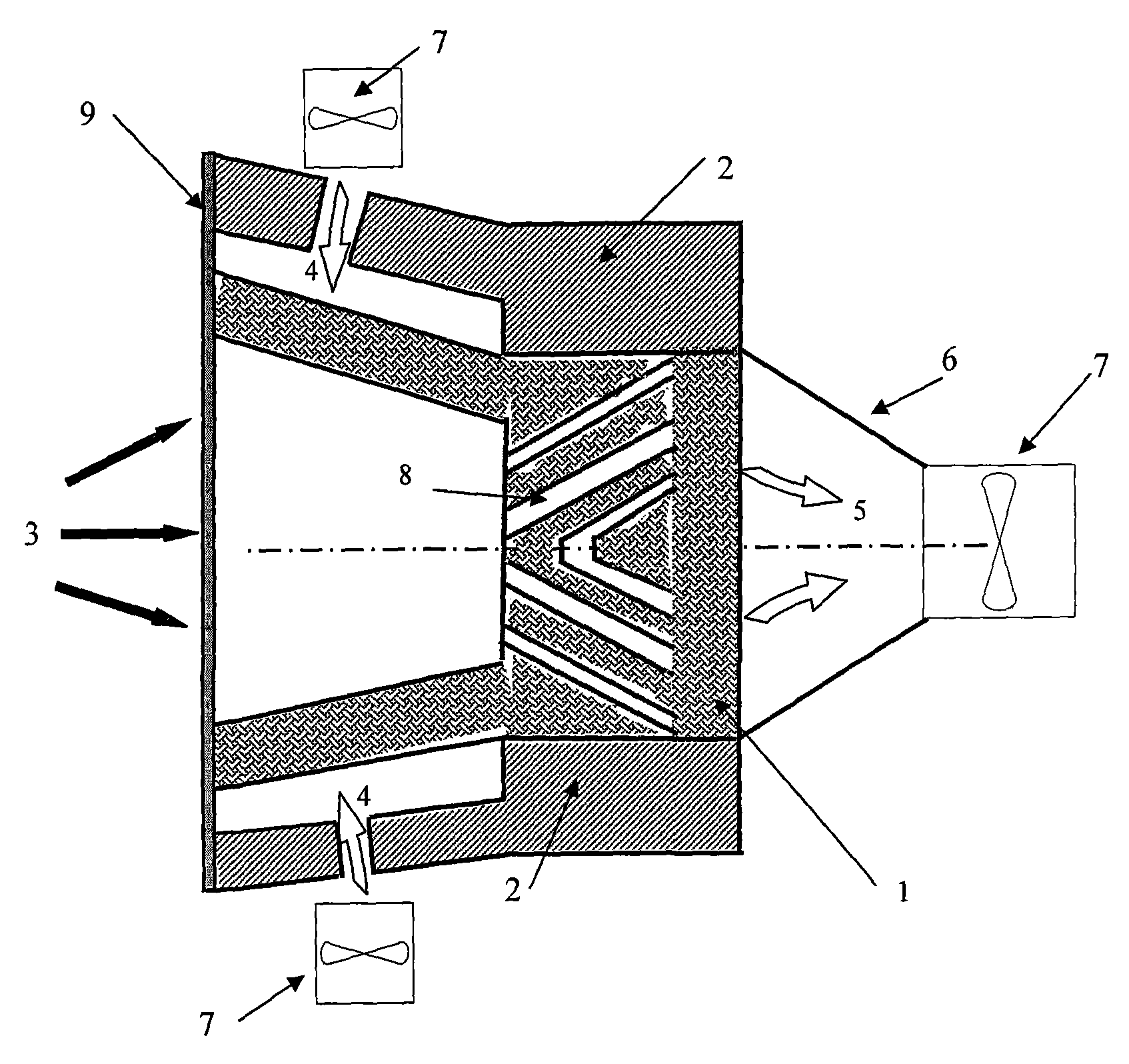
图4本发明顺流密封空腔方式碳化硅泡沫陶瓷太阳能空气吸热器结构示意图;Fig. 4 is a structural schematic diagram of a silicon carbide foam ceramic solar air heat absorber in a downstream sealed cavity mode of the present invention;
图5本发明逆流密封空腔方式碳化硅泡沫陶瓷太阳能空气吸热器结构示意图;Fig. 5 is a structural schematic diagram of a silicon carbide foam ceramic solar air heat absorber in the form of a counterflow sealed cavity of the present invention;
图中:1碳化硅泡沫陶瓷接收体、2保温层、3辐射热流、4冷空气、5热空气、6导流装置、7风机、8空气导流通道、9、人工黑体空腔、10石英玻璃窗、11多孔表面吸热体12骨架、13孔隙。In the figure: 1 silicon carbide foam ceramic receiver, 2 insulation layer, 3 radiant heat flow, 4 cold air, 5 hot air, 6 diversion device, 7 fan, 8 air diversion channel, 9, artificial black body cavity, 10 quartz Glass window, 11 porous surface heat absorber, 12 skeleton, 13 pores.
具体实施方式Detailed ways
本发明有表面式、人工黑体式两种外部受光方式和顺流、逆流两种密封空腔方式。The invention has two external light-receiving modes of surface type and artificial black body type, and two sealing cavity modes of forward flow and reverse flow.
图2所示为本发明表面式外部受光方式碳化硅泡沫陶瓷太阳能空气吸热器结构。碳化硅泡沫陶瓷接收体1外部包有保温层2,碳化硅泡沫陶瓷接收体1与导流装置6密封连接,导流装置6与风机7密封连接,碳化硅泡沫陶瓷接收体1在接收辐射侧预埋有空气导流通道8,其结构是斜圆柱孔、直圆柱孔或者二者的组合,其尺寸和孔结构的选择由空气流场参数和投入辐射的分布情况决定,其原则是既做到不同温度的空气充分混合又能使系统空气流动阻力最小。如当投入辐射在吸热体中心部位较为强烈其余部位较为均匀时,则在靠近中心位置预留有与吸热体周围相互连通的气流通道,将中心部位的高温空气导流至周围空气温度较低的区域混合,形成较温度较为均匀的空气流出吸热体,同时考虑空气流动过程的阻力特征,选择合适的空气流道几何结构,如斜圆柱与直圆柱的组合。碳化硅泡沫陶瓷接收体1的孔隙尺寸、截面形状、体积等由热空气5出口温度和投入辐射能等决定,如公式1。Fig. 2 shows the structure of the surface type silicon carbide foam ceramic solar air heat absorber of the present invention. The silicon carbide
∫AG(A)dA+n&airCpair(Tin-Tout)-ρceramicCpceramic∫/ΔTceramic(V)dV=0 (1)∫ A G(A)dA+n& air C pair (T in -T out )-ρ ceramic C pceramic ∫ / Δ Tceramic (V)dV=0 (1)
式中G为太阳投入辐射,n&为质量流量,Cp为比热,T为温度,下标in,out分别为表示接收体的入口和出口,ρ为密度,下标ceramic表示碳化硅陶瓷骨架,air表示空气,A表示陶瓷骨架截面面积,V表示陶瓷骨架体积。其中截面面积与孔隙尺寸和截面形状有关。保温层2采用的材料要求其长期使用温度不低于1600℃,以保证在高温应用时不发生毁坏,而且要求有良好的化学稳定性,导流装置6可以根据获得热空气5的出口温度、压力设计外形,如采用方程(2)的双曲面、方程(3)的椭圆抛物曲和由方程(2)、(3)分段组合而成的复杂锥面等。In the formula, G is the input radiation from the sun, n& is the mass flow rate, C p is the specific heat, T is the temperature, the subscripts in and out represent the inlet and outlet of the receiver respectively, ρ is the density, and the subscript ceramic represents the silicon carbide ceramic skeleton , air represents air, A represents the cross-sectional area of the ceramic skeleton, and V represents the volume of the ceramic skeleton. The cross-sectional area is related to the pore size and cross-sectional shape. The material used for the
式中a,b为可调常数。In the formula, a and b are adjustable constants.
工作时,碳化硅泡沫陶瓷接收体1接收到辐射热流3,冷空气4流入碳化硅泡沫陶瓷接收体1被加热,经导流装置6和风机7的作用获得热空气5。During operation, silicon carbide
图3所示为本发明人工黑体式外部受光方式碳化硅泡沫陶瓷太阳能空气吸热器结构。碳化硅泡沫陶瓷接收体1外部包有保温层2,碳化硅泡沫陶瓷接收体1与导流装置6密封连接,导流装置6与风机7密封连接,碳化硅泡沫陶瓷接收体1被加工成空腔形式,空腔内表面自身发射和反射的辐射能量相互吸收,构造为人工黑体空腔9,最大可能的利用太阳辐射能,碳化硅泡沫陶瓷接收体1预埋有空气导流通道8,其结构是斜圆柱孔、直圆柱孔或者二者的组合,其尺寸和孔结构的选择由空气流场参数和投入辐射的分布情况决定,其原则是既做到不同温度的空气充分混合又能系统空气流动阻力最小。如当投入辐射在吸热体中心部位较为强烈其余部位较为均匀时,则在靠近中心位置预留有与吸热体周围相互连通的气流通道,将中心部位的高温空气导流至周围空气温度较低的区域混合,形成较温度较为均匀的空气流出吸热体,同时考虑空气流动过程的阻力特征,选择合适的空气流道几何结构,如斜圆柱与直圆柱的组合。碳化硅泡沫陶瓷接收体1的孔隙尺寸、截面形状、体积等由热空气5出口温度和投入辐射能等决定,如公式1。保温层2采用的材料要求其长期使用温度不低于1600℃,以保证在高温应用时不发生毁坏,而且要求有良好的化学稳定性,导流装置6可以根据获得热空气5的出口温度、压力设计外形,如采用方程(2)的双曲面、方程(3)的椭圆抛物曲和由方程(2)、(3)分段组合而成的复杂锥面等。工作时,碳化硅泡沫陶瓷接收体1接收到辐射热流3,冷空气4流入碳化硅泡沫陶瓷接收体1被加热,经导流装置6和风机7的作用获得热空气5,人工黑体空腔9内表面进行相互吸收和发射辐射。Fig. 3 shows the structure of the artificial black body type silicon carbide foam ceramic solar air heat absorber of the present invention which receives light from the outside. The silicon carbide
图4所示为本发明顺流密封空腔方式碳化硅泡沫陶瓷太阳能空气吸热器结构。碳化硅泡沫陶瓷接收体1外部包有保温层2,碳化硅泡沫陶瓷接收体1与导流装置6密封连接,导流装置6与风机7密封连接,石英玻璃窗10与碳化硅泡沫陶瓷接收体1和保温层2密封连接,碳化硅泡沫陶瓷接收体1在接收辐射侧预埋有空气导流通道8,其结构是斜圆柱孔、直圆柱孔或者二者的组合,其尺寸和孔结构的选择由空气流场参数和投入辐射的分布情况决定,其原则是既做到不同温度的空气充分混合又能系统空气流动阻力最小。如当投入辐射在吸热体中心部位较为强烈其余部位较为均匀时,则在靠近中心位置预留有与吸热体周围相互连通的气流通道,将中心部位的高温空气导流至周围空气温度较低的区域混合,形成较温度较为均匀的空气流出吸热体,同时考虑空气流动过程的阻力特征,选择合适的空气流道几何结构,如斜圆柱与直圆柱的组合。碳化硅泡沫陶瓷接收体1的孔隙尺寸、截面形状、体积等由热空气5出口温度、空气流动过程压力损失和投入辐射能等决定,保温层2采用的材料要求其长期使用温度不低于1600℃,以保证在高温应用时不发生毁坏,而且要求有良好的化学稳定性,导流装置6可以根据获得热空气5的出口温度、压力设计外形,如采用方程(2)的双曲面、方程(3)的椭圆抛物曲面或由方程(2)、(3)分段组合而成的复杂锥面。石英玻璃窗10的形状可以是平面也可以是凹面,根据投入辐射方向选择。工作时,辐射热流3透过石英玻璃窗10,经风机7从环境中吹入冷空气4,冷空气4流经碳化硅泡沫陶瓷接收体1,碳化硅泡沫陶瓷接收体1外部包覆有保温层2以减少外部热损失,经碳化硅泡沫陶瓷接收体1加热后获得热空气5,整个太阳能空气吸热器在密封的环境下运行。Fig. 4 shows the structure of the silicon carbide foam ceramic solar air heat absorber of the present invention in a downstream sealed cavity mode. The silicon carbide
图5所示为本发明逆流密封空腔方式碳化硅泡沫陶瓷太阳能空气吸热器结构。碳化硅泡沫陶瓷接收体1外部包有保温层2,碳化硅泡沫陶瓷接收体1与导流装置6密封连接,导流装置6与风机7密封连接,石英玻璃窗10与碳化硅泡沫陶瓷接收体1和保温层2密封连接,碳化硅泡沫陶瓷接收体1预埋空气导流通道8,其结构是斜圆柱孔、直圆柱孔或者二者的组合,其尺寸和孔结构的选择由空气流场参数和投入辐射的分布情况决定,其原则是既做到不同温度的空气充分混合又能系统空气流动阻力最小。如当投入辐射在吸热体中心部位较为强烈其余部位较为均匀时,则在靠近中心位置预留有与吸热体周围相互连通的气流通道,将中心部位的高温空气导流至周围空气温度较低的区域混合,形成较温度较为均匀的空气流出吸热体,同时考虑空气流动过程的阻力特征,选择合适的空气流道几何结构,如斜圆柱与直圆柱的组合。碳化硅泡沫陶瓷接收体1的孔隙尺寸、截面形状、体积等由热空气5出口温度、空气流动过程压力损失和投入辐射能等决定,保温层2采用的材料要求其长期使用温度不低于1600℃,以保证在高温应用时不发生毁坏,而且要求有良好的化学稳定性,导流装置6可以根据获得热空气5的出口温度、压力设计外形,如采用方程(2)的双曲面、方程(3)的椭圆抛物曲或由方程(2)、(3)分段组合而成的复杂锥面。石英玻璃窗10的形状可以是平面也可以是凹面,根据投入辐射方向选择。工作时,辐射热流3透过石英玻璃窗10,经风机7从环境中抽入冷空气4,冷空气4流经碳化硅泡沫陶瓷接收体1,碳化硅泡沫陶瓷接收体1外部包覆有保温层2以减少外部热损失,经碳化硅泡沫陶瓷接收体1加热后获得热空气5,整个太阳能空气吸热器在密封的环境下运行。Fig. 5 shows the structure of the solar air heat absorber of silicon carbide foam ceramics in the form of counterflow sealed cavity of the present invention. The silicon carbide
Claims (5)
Priority Applications (1)
| Application Number | Priority Date | Filing Date | Title |
|---|---|---|---|
| CN2007100990393A CN101122425B (en) | 2007-05-10 | 2007-05-10 | A silicon carbide foam ceramic solar air heat absorber |
Applications Claiming Priority (1)
| Application Number | Priority Date | Filing Date | Title |
|---|---|---|---|
| CN2007100990393A CN101122425B (en) | 2007-05-10 | 2007-05-10 | A silicon carbide foam ceramic solar air heat absorber |
Publications (2)
| Publication Number | Publication Date |
|---|---|
| CN101122425A true CN101122425A (en) | 2008-02-13 |
| CN101122425B CN101122425B (en) | 2012-03-28 |
Family
ID=39084861
Family Applications (1)
| Application Number | Title | Priority Date | Filing Date |
|---|---|---|---|
| CN2007100990393A Expired - Fee Related CN101122425B (en) | 2007-05-10 | 2007-05-10 | A silicon carbide foam ceramic solar air heat absorber |
Country Status (1)
| Country | Link |
|---|---|
| CN (1) | CN101122425B (en) |
Cited By (28)
| Publication number | Priority date | Publication date | Assignee | Title |
|---|---|---|---|---|
| CN101886846A (en) * | 2010-06-25 | 2010-11-17 | 河海大学 | Measurement and control system and performance, temperature prediction and protection method of solar air heat absorber |
| CN101307956B (en) * | 2008-06-24 | 2011-02-09 | 中国科学院电工研究所 | A kind of pressurized air heat absorber for solar thermal power station |
| CN102317705A (en) * | 2009-02-12 | 2012-01-11 | 曳达研究和发展有限公司 | The solar receiver system |
| CN102650469A (en) * | 2012-04-26 | 2012-08-29 | 宜兴市华瑞铸造材料有限公司 | Novel silicon carbide foam ceramic solar energy air heat absorber |
| CN103273695A (en) * | 2013-05-22 | 2013-09-04 | 中国大唐集团科学技术研究院有限公司 | Silicon carbide foam/metal matrix photothermal composite material and preparation method thereof |
| CN103392100A (en) * | 2010-12-06 | 2013-11-13 | 阿尔斯通技术有限公司 | Improved solar receiver |
| CN104061694A (en) * | 2014-07-01 | 2014-09-24 | 福建工程学院 | Solar heat absorber with composite rib structure |
| CN104061690A (en) * | 2014-07-01 | 2014-09-24 | 福建工程学院 | Solar energy heat absorber with increased dielectric absorption coefficient gradient |
| CN104075460A (en) * | 2014-07-01 | 2014-10-01 | 福建工程学院 | Solar heat absorber with novel optical window |
| US8960184B2 (en) | 2008-08-31 | 2015-02-24 | Yeda Research And Development Co. Ltd. | Solar receiver system |
| CN105066478A (en) * | 2015-08-31 | 2015-11-18 | 华南理工大学 | Circular-truncated-cone-shaped cavity type solar heat absorber with double-row multiple tubes |
| CN105758020A (en) * | 2016-03-10 | 2016-07-13 | 浙江大学 | Heat absorber phase-change material heat-preservation method and device for tower type solar thermal power plant |
| CN106839474A (en) * | 2017-01-19 | 2017-06-13 | 西安交通大学 | A kind of porous media solar heat absorber and its method for designing |
| CN107084541A (en) * | 2017-05-27 | 2017-08-22 | 南京航空航天大学 | A kind of new and effective solar porous medium heat dump |
| CN107763865A (en) * | 2017-09-29 | 2018-03-06 | 西安交通大学 | A kind of spill target surface porous ceramics solar air heat absorber core body |
| CN108266901A (en) * | 2016-08-04 | 2018-07-10 | 福建工程学院 | A kind of air vacuum tube solar thermal collector |
| CN108645060A (en) * | 2018-04-26 | 2018-10-12 | 福建工程学院 | A kind of three layers of mixing gradient-structure solar energy high temperature heat dump |
| CN109812984A (en) * | 2018-12-29 | 2019-05-28 | 南京航空航天大学 | A kind of solar porous medium heat dump with volume effect |
| CN110307654A (en) * | 2019-07-23 | 2019-10-08 | 南通万达锅炉有限公司 | A kind of positive displacement solar heat dump |
| CN112344571A (en) * | 2020-10-22 | 2021-02-09 | 苏州大学 | A cavity-type photonic crystal selective absorption radiator |
| CN113137770A (en) * | 2021-04-23 | 2021-07-20 | 新疆大学 | Light-gathering, power-generating and heat-collecting integrated device based on blackbody cavity |
| CN113294919A (en) * | 2021-06-09 | 2021-08-24 | 湖南科技大学 | Positive displacement solar cavity heat absorber with rotary heat absorber |
| CN114543058A (en) * | 2022-02-25 | 2022-05-27 | 中国科学院电工研究所 | High-temperature steam generator based on solar energy |
| CN115263875A (en) * | 2022-07-29 | 2022-11-01 | 安徽工业大学 | Flue bifurcated fluid flow dividing device and application thereof |
| CN116026047A (en) * | 2023-02-07 | 2023-04-28 | 哈尔滨工业大学 | Uniform solar reactor designed by combining energy flow distribution and absorbing coating |
| US11971197B2 (en) * | 2011-09-21 | 2024-04-30 | King Saud University | Solid particle receiver with porous structure for flow regulation and enhancement of heat transfer |
| EP4621309A1 (en) * | 2024-03-22 | 2025-09-24 | General Electric Company | Heat exchanger assembly |
| EP4621308A1 (en) * | 2024-03-22 | 2025-09-24 | General Electric Company | Heat exchanger assembly |
Family Cites Families (6)
| Publication number | Priority date | Publication date | Assignee | Title |
|---|---|---|---|---|
| CN2148925Y (en) * | 1992-11-22 | 1993-12-08 | 刘玉玺 | Solar energy heat sink |
| DE19740644C2 (en) * | 1997-09-16 | 2001-05-17 | Deutsch Zentr Luft & Raumfahrt | Solar receiver with at least one porous absorber body made of ceramic material |
| DE10007648C1 (en) * | 2000-02-19 | 2001-09-06 | Deutsch Zentr Luft & Raumfahrt | High temperature solar absorber |
| DE10257458A1 (en) * | 2002-12-09 | 2004-06-24 | Saint-Gobain Industriekeramik Rödental GmbH | Ceramic body for solar thermal reception unit for solar thermal power plant has lengths of flow medium channels reduced towards ceramic body edge over at least one section of edge region |
| EP1475581A1 (en) * | 2003-05-09 | 2004-11-10 | Paul Scherrer Institut | Reactor for indirect utilization of external radiation heat |
| CN2872208Y (en) * | 2006-03-28 | 2007-02-21 | 张耀明 | Hollow solar energy collector |
-
2007
- 2007-05-10 CN CN2007100990393A patent/CN101122425B/en not_active Expired - Fee Related
Cited By (34)
| Publication number | Priority date | Publication date | Assignee | Title |
|---|---|---|---|---|
| CN101307956B (en) * | 2008-06-24 | 2011-02-09 | 中国科学院电工研究所 | A kind of pressurized air heat absorber for solar thermal power station |
| US8960184B2 (en) | 2008-08-31 | 2015-02-24 | Yeda Research And Development Co. Ltd. | Solar receiver system |
| CN102317705A (en) * | 2009-02-12 | 2012-01-11 | 曳达研究和发展有限公司 | The solar receiver system |
| CN101886846A (en) * | 2010-06-25 | 2010-11-17 | 河海大学 | Measurement and control system and performance, temperature prediction and protection method of solar air heat absorber |
| CN101886846B (en) * | 2010-06-25 | 2012-09-26 | 河海大学 | Solar air heat absorber measurement and control system and performance and temperature prediction and protection method |
| CN103392100A (en) * | 2010-12-06 | 2013-11-13 | 阿尔斯通技术有限公司 | Improved solar receiver |
| US11971197B2 (en) * | 2011-09-21 | 2024-04-30 | King Saud University | Solid particle receiver with porous structure for flow regulation and enhancement of heat transfer |
| CN102650469A (en) * | 2012-04-26 | 2012-08-29 | 宜兴市华瑞铸造材料有限公司 | Novel silicon carbide foam ceramic solar energy air heat absorber |
| CN103273695A (en) * | 2013-05-22 | 2013-09-04 | 中国大唐集团科学技术研究院有限公司 | Silicon carbide foam/metal matrix photothermal composite material and preparation method thereof |
| CN104061690A (en) * | 2014-07-01 | 2014-09-24 | 福建工程学院 | Solar energy heat absorber with increased dielectric absorption coefficient gradient |
| CN104075460A (en) * | 2014-07-01 | 2014-10-01 | 福建工程学院 | Solar heat absorber with novel optical window |
| CN104061694A (en) * | 2014-07-01 | 2014-09-24 | 福建工程学院 | Solar heat absorber with composite rib structure |
| CN105066478A (en) * | 2015-08-31 | 2015-11-18 | 华南理工大学 | Circular-truncated-cone-shaped cavity type solar heat absorber with double-row multiple tubes |
| CN105758020A (en) * | 2016-03-10 | 2016-07-13 | 浙江大学 | Heat absorber phase-change material heat-preservation method and device for tower type solar thermal power plant |
| CN108266901A (en) * | 2016-08-04 | 2018-07-10 | 福建工程学院 | A kind of air vacuum tube solar thermal collector |
| CN106839474A (en) * | 2017-01-19 | 2017-06-13 | 西安交通大学 | A kind of porous media solar heat absorber and its method for designing |
| CN107084541A (en) * | 2017-05-27 | 2017-08-22 | 南京航空航天大学 | A kind of new and effective solar porous medium heat dump |
| CN107763865A (en) * | 2017-09-29 | 2018-03-06 | 西安交通大学 | A kind of spill target surface porous ceramics solar air heat absorber core body |
| CN108645060A (en) * | 2018-04-26 | 2018-10-12 | 福建工程学院 | A kind of three layers of mixing gradient-structure solar energy high temperature heat dump |
| CN108645060B (en) * | 2018-04-26 | 2020-09-22 | 福建工程学院 | A three-layer hybrid gradient structure solar high temperature heat absorber |
| CN109812984A (en) * | 2018-12-29 | 2019-05-28 | 南京航空航天大学 | A kind of solar porous medium heat dump with volume effect |
| CN110307654A (en) * | 2019-07-23 | 2019-10-08 | 南通万达锅炉有限公司 | A kind of positive displacement solar heat dump |
| CN110307654B (en) * | 2019-07-23 | 2024-05-31 | 南通万达能源动力科技有限公司 | Volumetric solar heat absorber |
| CN112344571A (en) * | 2020-10-22 | 2021-02-09 | 苏州大学 | A cavity-type photonic crystal selective absorption radiator |
| CN113137770A (en) * | 2021-04-23 | 2021-07-20 | 新疆大学 | Light-gathering, power-generating and heat-collecting integrated device based on blackbody cavity |
| CN113294919A (en) * | 2021-06-09 | 2021-08-24 | 湖南科技大学 | Positive displacement solar cavity heat absorber with rotary heat absorber |
| CN114543058B (en) * | 2022-02-25 | 2023-07-21 | 中国科学院电工研究所 | A high temperature steam generator based on solar energy |
| CN114543058A (en) * | 2022-02-25 | 2022-05-27 | 中国科学院电工研究所 | High-temperature steam generator based on solar energy |
| CN115263875A (en) * | 2022-07-29 | 2022-11-01 | 安徽工业大学 | Flue bifurcated fluid flow dividing device and application thereof |
| CN115263875B (en) * | 2022-07-29 | 2026-02-03 | 安徽工业大学 | Flue bifurcation type fluid diversion device and application thereof |
| CN116026047A (en) * | 2023-02-07 | 2023-04-28 | 哈尔滨工业大学 | Uniform solar reactor designed by combining energy flow distribution and absorbing coating |
| CN116026047B (en) * | 2023-02-07 | 2024-12-24 | 哈尔滨工业大学 | Uniform heating type solar reactor combining energy flow distribution and absorption coating design |
| EP4621309A1 (en) * | 2024-03-22 | 2025-09-24 | General Electric Company | Heat exchanger assembly |
| EP4621308A1 (en) * | 2024-03-22 | 2025-09-24 | General Electric Company | Heat exchanger assembly |
Also Published As
| Publication number | Publication date |
|---|---|
| CN101122425B (en) | 2012-03-28 |
Similar Documents
| Publication | Publication Date | Title |
|---|---|---|
| CN101122425A (en) | A silicon carbide foam ceramic solar air heat absorber | |
| CN101307956B (en) | A kind of pressurized air heat absorber for solar thermal power station | |
| CN104197537B (en) | The displacement air heat extractor that a kind of absorber rotates | |
| CN104153954B (en) | Multi-mode tower type solar energy thermal power generation device | |
| CN101737957B (en) | Heat-absorbing body rotary air heat absorber for solar thermal power station | |
| CN103423887B (en) | Fluidized bed air heat absorber used for solar thermal power generation | |
| CN103075816B (en) | A kind of high temperature heat absorber based on disc type solar energy electricity generation system | |
| CN103216952B (en) | Internal circulation type solid particle air heat absorber for solar thermal power generation | |
| CN101634490B (en) | Solid ball flow absorber for solar thermal power generation | |
| CN209586603U (en) | Three-tank type fused salt heat storage tower trough coupling photo-thermal power generation system | |
| CN102135334A (en) | Silica glass tube bundle type air heat absorber for solar heat generating station | |
| CN103499230A (en) | Solar thermochemistry energy storage heat absorber and heat absorbing method thereof | |
| CN105387634B (en) | A kind of jet-flow efficient heat exchange solar energy heat absorbing device | |
| CN205156393U (en) | Fused salt heat absorber | |
| CN107084541A (en) | A kind of new and effective solar porous medium heat dump | |
| CN103148602A (en) | Solid particle accumulation bed-type air heat absorber for solar thermal power station | |
| CN209101582U (en) | A cavity solar heat absorber device | |
| CN102818379A (en) | Solid-particle air heat absorber used for solar thermal power plant | |
| CN203810744U (en) | Improved cavity type solar receiver | |
| CN101111728B (en) | Volumetric Solar Receiver | |
| CN107166750A (en) | A kind of two grades of heating volume formula solar air receivers | |
| CN113465194B (en) | Solar heat absorber with low surface temperature deviation | |
| CN207230977U (en) | A kind of efficient solar porous medium heat dump | |
| CN202747646U (en) | Solar photothermal receiver | |
| CN208817746U (en) | An exposed heat absorber suitable for tower solar thermal power station |
Legal Events
| Date | Code | Title | Description |
|---|---|---|---|
| C06 | Publication | ||
| PB01 | Publication | ||
| C10 | Entry into substantive examination | ||
| SE01 | Entry into force of request for substantive examination | ||
| C14 | Grant of patent or utility model | ||
| GR01 | Patent grant | ||
| CF01 | Termination of patent right due to non-payment of annual fee | ||
| CF01 | Termination of patent right due to non-payment of annual fee |
Granted publication date: 20120328 Termination date: 20180510 |