Disclosure of Invention
In view of the above, the main objective of the present invention is to provide a method and a system for intelligent monitoring of panoramic video, which can obtain panoramic images and reduce installation cost; furthermore, the abnormal conditions appearing in the picture are automatically distinguished according to the intelligent analysis result, the target detection, tracking, classification and behavior analysis are implemented, the automatic alarm is realized, the occurrence of events is effectively prevented, and the manpower and material resources are saved.
Another object of the present invention is to provide an apparatus for performing intelligent analysis processing on a panoramic image, wherein the apparatus automatically distinguishes "abnormalities" appearing in a picture, performs target detection, tracking, classification and behavior analysis, realizes automatic alarm, effectively prevents an event from occurring, and saves manpower and material resources.
The invention also aims to provide a method and a device for unfolding the panoramic image, so that the scene information in the image is more visual, the scene layout is more obvious, and a user can conveniently understand the scene layout.
In order to achieve the purpose, the technical scheme of the invention is realized as follows:
the invention provides an intelligent panoramic video monitoring method, which comprises the following steps:
A. acquiring a field panoramic image;
B. and unfolding the panoramic image, and intelligently analyzing the moving target in the panoramic unfolded image.
Wherein, the unfolding panoramic image in the step B is as follows:
b1, establishing a new coordinate system with the center of the panoramic image as an origin, and calculating the coordinates of each pixel point in the panoramic image in the new coordinate system;
b2, determining the shape characteristics of the unfolded image and the coordinate corresponding relation between the panoramic image and the unfolded image;
b3, calculating the coordinates in the panoramic image corresponding to each pixel point in the unfolded image according to the corresponding relation of the coordinates;
and B4, carrying out nonlinear interpolation calculation on the pixel values of the pixel points in the panoramic image according to the calculated coordinates to obtain the pixel value of each pixel point in the corresponding expanded image.
Further comprising between the steps B1 and B2:
b11, removing a concentric circle with the origin as the center in the panoramic image.
When the expanded image is a rectangular expanded image, the step B2 is: the height and width of the rectangular unfolded image are determined.
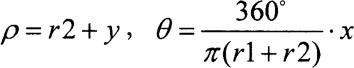
The coordinate correspondence in step B3 is:
wherein ρ is a distance between a pixel point in the panoramic image and a coordinate origin, θ is an included angle between the pixel point in the panoramic image and a coordinate axis, x is an abscissa of the pixel point in the expanded image, y is an ordinate of the pixel point in the expanded image, r2 is a radius of the concentric circle, r1 is a radius of the panoramic image, and π is a circumference ratio.
Wherein the step B1 is:
setting the radius of the panoramic image to be 1, and calculating the coordinates of each pixel point in the panoramic image in a unit circle.
The step B2 is as follows:
and calculating the distance between each pixel point and the original point in the unfolded image, the included angle between the pixel point and the coordinate axis and the maximum stretching ratio of the pixel point on the connecting line with the original point.
The coordinate correspondence in step B3 is:
r′=r/Rmax,θ′=θ
wherein R 'is the distance between a pixel point and an origin in the panoramic image, theta' is the included angle between the pixel point and a coordinate axis in the panoramic image, theta is the included angle between the pixel point and the coordinate axis in the expanded image, R is the distance between the pixel point and the origin in the expanded image, and R is the distance between the pixel point and the origin in the expanded imagemaxFor the maximum stretching ratio, R, of the pixel point in the unfolded image to the pixel point on the connecting line of the original pointmax=1/cosθ。
Or, the coordinate correspondence relationship in step B3 is:
<math><mrow><msup><mi>r</mi><mo>′</mo></msup><mo>=</mo><mfrac><mi>r</mi><mrow><mrow><mo>(</mo><msub><mi>R</mi><mi>max</mi></msub><mo>-</mo><mn>1</mn><mo>)</mo></mrow><mo>×</mo><mrow><mo>(</mo><mi>r</mi><mo>/</mo><msub><mi>R</mi><mi>max</mi></msub><mo>)</mo></mrow><mo>×</mo><mrow><mo>(</mo><mi>r</mi><mo>/</mo><msub><mi>R</mi><mi>max</mi></msub><mo>)</mo></mrow><mo>+</mo><mn>1</mn></mrow></mfrac><mo>,</mo></mrow></math> θ′=θ
wherein r 'is the distance between a pixel point and an origin point in the panoramic image, and theta' is the distance between the pixel point and the origin point in the panoramic imageThe included angle between the pixel point and the coordinate axis, theta is the included angle between the pixel point and the coordinate axis in the expanded image, R is the distance between the pixel point and the original point in the expanded image, and R is the distance between the pixel point and the original pointmaxFor the maximum stretching ratio, R, of the pixel point in the unfolded image to the pixel point on the connecting line of the original pointmax=1/cosθ。
In the step B, the intelligent analysis of the moving target in the panoramic expansion image comprises the following steps:
and detecting, tracking, type recognition and behavior analysis are carried out on the moving target.
Step B further comprises the following steps:
C. and determining the execution of the alarm processing and executing the alarm processing.
The alarm processing in the step C is as follows:
controlling external equipment to make corresponding alarm processing; or,
sending an intelligent analysis result, on-site video information and alarm information to a local monitoring terminal; or,
sending an intelligent analysis result, on-site video information and alarm information to an intelligent monitoring platform;
or any combination of the above.
Step C further comprises the following steps:
D. the local monitoring terminal amplifies and displays the user designated area according to the received intelligent analysis result, the field video information and the alarm information; and/or the presence of a gas in the gas,
the local monitoring terminal identifies the detected moving target and the moving track thereof according to the received intelligent analysis result, the field video information and the alarm information; and,
the intelligent monitoring platform stores the received intelligent analysis result, the field video information and the alarm information, and displays, stores, plays back and retrieves the field video information.
Further comprising after step D:
E. and the intelligent monitoring platform sends an intelligent analysis result, field video information and alarm information to the remote monitoring terminal and simultaneously controls the field monitoring equipment to perform linkage alarm.
Further comprising the following steps between the steps D and E:
e0, the remote monitoring terminal requests the intelligent monitoring platform to send the intelligent analysis result, the on-site video information and the alarm information.
Step E is further followed by:
F. the remote monitoring terminal amplifies and displays the designated area of the user according to the received intelligent analysis result, the on-site video information and the alarm information; and/or the presence of a gas in the gas,
and the local monitoring terminal identifies the detected moving target and the moving track thereof on the panoramic expansion image according to the received intelligent analysis result, the field video information and the alarm information.
The proceeding identification is as follows: framing the detected moving target by using a rectangular frame, and representing the moving track of the moving target by using a curve; alternatively, the area of detected smoke is outlined, as well as the shape of the diffusion.
The points making up the curve are the centroid positions of the detected moving objects in the previous frame.
The invention also provides a panoramic video intelligent monitoring system, which comprises a front-end panoramic imaging device, an intelligent analysis processing device and an intelligent monitoring platform, wherein,
the front-end panoramic imaging device is used for acquiring field video information, monitoring a scene at 360 degrees without blind spots and sending the field video information to the intelligent analysis processing device;
the intelligent analysis processing equipment is used for intelligently analyzing and processing the field video information, sending an intelligent analysis processing result, the field video information and the alarm information to the intelligent monitoring platform and the local monitoring terminal, and controlling external equipment to alarm;
the intelligent monitoring platform is used for processing the intelligent analysis processing result, the field video information and the alarm information, and displaying, storing, replaying and retrieving the field video information; the system is also used for configuring and maintaining the front-end panoramic imaging equipment and the intelligent analysis processing equipment of the local end; the system is also used for transmitting the alarm information and the on-site video information to a remote monitoring terminal according to the requirements of customers; and the system is also used for controlling the field monitoring equipment to carry out linkage alarm.
Wherein the system further comprises:
the local monitoring terminal is used for receiving the intelligent analysis result, the field video information and the alarm information transmitted by the intelligent analysis processing equipment and informing the user of the alarm information;
and the remote monitoring terminal is used for receiving the intelligent analysis result, the field video information and the alarm information transmitted by the intelligent monitoring platform and informing the user of the alarm information.
The intelligent analysis processing device comprises a panoramic image expansion processing module, a moving target detection module, a moving target tracking module, a moving target classification module, a moving target behavior analysis module, an external device control module and a data communication module, wherein,
the panoramic image unfolding processing module is used for unfolding the received panoramic image to obtain a panoramic unfolded image;
the moving object detection module is used for detecting pixels of the current frame of the panoramic expansion image which are not matched with the background model, and extracting a foreground object of the current frame after the pixels are connected;
the moving target tracking module is used for tracking the foreground target extracted by the moving target detection module;
the moving target classification module is used for identifying the type of a tracking target in the moving target tracking module;
the moving target behavior analysis module comprehensively utilizes the information obtained from the moving target detection module, the moving target tracking module and the moving target classification module to analyze the behavior characteristics of the target and judge whether an event meeting the alarm condition stored in the memory occurs; if the 'event' meeting the alarm condition exists, entering an external equipment control module and a data communication module, and if the 'event' does not exist, entering a panoramic image expansion processing module;
the external equipment control module is used for controlling the external equipment to perform corresponding alarm processing;
and the data communication module is used for sending the intelligent analysis processing result, the field video information and the alarm information to the local monitoring terminal and the intelligent monitoring platform.
The panoramic image expansion processing module comprises a coordinate system transformation module, a shape characteristic determination module, a coordinate calculation module and a pixel value calculation module,
the coordinate system transformation module is used for establishing a new coordinate system with the center of the panoramic image as an origin, calculating the coordinates of each pixel point in the panoramic image in the new coordinate system and sending the obtained coordinates of each pixel point to the coordinate calculation module;
the shape characteristic determining module is used for determining the shape characteristic of a corresponding unfolded image according to different unfolding methods selected by a user and sending the shape characteristic to the coordinate calculating module;
the coordinate calculation module is used for calculating the coordinate in the panoramic image corresponding to each pixel point in the unfolded image according to the shape characteristic and the coordinate of each pixel point and sending the obtained coordinate to the pixel value calculation module;
and the pixel value calculating module is used for calculating the pixel value corresponding to the pixel point in each expanded image by carrying out nonlinear interpolation calculation on the pixel value of the pixel point in the panoramic image according to the coordinate sent by the coordinate calculating module.
The intelligent monitoring platform further comprises:
and the data storage unit is used for storing the intelligent analysis processing result, the field video information and the alarm information.
The local monitoring terminal and the remote monitoring terminal further comprise:
the virtual holder control module is used for amplifying and displaying a user designated area; and/or the presence of a gas in the gas,
and the detection event representation module is used for identifying the detected moving target and the moving track thereof according to the received intelligent analysis result, the field video information and the alarm information.
The invention also provides a device for intelligently analyzing and processing the panoramic image, which comprises a panoramic image expansion processing module, a moving target detection module, a moving target tracking module, a moving target classification module, a moving target behavior analysis module, an external device control module and a data communication module, wherein,
the panoramic image unfolding processing module is used for unfolding the received panoramic image;
the moving object detection module is used for detecting pixels of the panoramic expansion image, which are not matched with the background model, and extracting a foreground object of the current frame after the pixels are connected;
the moving target tracking module is used for tracking the foreground target extracted by the moving target detection module;
the moving target classification module is used for identifying the type of a tracking target in the moving target tracking module;
the moving target behavior analysis module comprehensively utilizes the information obtained from the moving target detection module, the moving target tracking module and the moving target classification module to analyze the behavior characteristics of the target and judge whether an event meeting the alarm condition stored in the memory occurs; if the 'event' meeting the alarm condition exists, entering an external equipment control module and a data communication module, and if the 'event' does not exist, entering a panoramic image expansion processing module;
the external equipment control module is used for controlling the external equipment to perform corresponding alarm processing;
and the data communication module is used for sending the intelligent analysis result, the field video information and the alarm information to the local monitoring terminal and the intelligent monitoring platform.
The panoramic image expansion processing module further comprises:
the coordinate system transformation module is used for establishing a new coordinate system with the center of the panoramic image as an origin, calculating the coordinates of each pixel point in the panoramic image in the new coordinate system and sending the obtained coordinates of each pixel point to the coordinate calculation module;
the shape characteristic determining module is used for determining the shape characteristic of a corresponding unfolded image according to different unfolding methods selected by a user and sending the shape characteristic to the coordinate calculating module;
the coordinate calculation module is used for calculating the coordinate in the panoramic image corresponding to each pixel point in the unfolded image according to the shape characteristic and the coordinate of each pixel point and sending the obtained coordinate to the pixel value calculation module;
and the pixel value calculating module is used for calculating the pixel value corresponding to the pixel point in each expanded image by carrying out nonlinear interpolation calculation on the pixel value of the pixel point in the panoramic image according to the coordinate sent by the coordinate calculating module.
The invention also provides a method for unfolding the panoramic image, which comprises the following steps:
1) establishing a new coordinate system with the center of the panoramic image as an origin, and calculating the coordinates of each pixel point in the panoramic image in the new coordinate system;
2) determining the shape characteristic of the unfolded image and the coordinate corresponding relation between the panoramic image and the unfolded image;
3) calculating the coordinates of the pixel points in the panoramic image corresponding to each pixel point in the unfolded image according to the coordinate corresponding relation;
4) and carrying out nonlinear interpolation calculation on the pixel values of the pixel points in the panoramic image according to the calculated coordinates to obtain the pixel value of each pixel point in the corresponding expanded image.
Wherein between the steps 1) and 2) further comprising:
11) a concentric circle centered at the origin is removed from the panoramic image.
When the unfolded image is a rectangular unfolded image, the step 2) is as follows: the height and width of the rectangular unfolded image are determined.
The coordinate corresponding relation in the step 3) is as follows:
wherein ρ is a distance between a pixel point in the panoramic image and a coordinate origin, θ is an included angle between the pixel point in the panoramic image and a coordinate axis, x is an abscissa of the pixel point in the expanded image, y is an ordinate of the pixel point in the expanded image, r2 is a radius of the concentric circle, r1 is a radius of the panoramic image, and π is a circumference ratio.
The step 1) is as follows:
setting the radius of the panoramic image to be 1, and calculating the coordinates of each pixel point in the panoramic image in a unit circle.
The step 2) is as follows:
and calculating the distance between each pixel point and the original point in the unfolded image, the included angle between the pixel point and the coordinate axis and the maximum stretching ratio of the pixel point on the connecting line with the original point.
The coordinate corresponding relation in the step 3) is as follows:
r′=r/Rmax,θ′=θ
wherein R 'is the distance between a pixel point and an origin in the panoramic image, theta' is the included angle between the pixel point and a coordinate axis in the panoramic image, theta is the included angle between the pixel point and the coordinate axis in the expanded image, R is the distance between the pixel point and the origin in the expanded image, and R is the distance between the pixel point and the origin in the expanded imagemaxFor the maximum stretching ratio, R, of the pixel point in the unfolded image to the pixel point on the connecting line of the original pointmax=1/cosθ。
Or, the coordinate corresponding relation in the step 3) is as follows:
<math><mrow><msup><mi>r</mi><mo>′</mo></msup><mo>=</mo><mfrac><mi>r</mi><mrow><mrow><mo>(</mo><msub><mi>R</mi><mi>max</mi></msub><mo>-</mo><mn>1</mn><mo>)</mo></mrow><mo>×</mo><msup><mrow><mo>(</mo><mi>r</mi><mo>/</mo><msub><mi>R</mi><mi>max</mi></msub><mo>)</mo></mrow><mn>2</mn></msup><mo>+</mo><mn>1</mn></mrow></mfrac><mo>,</mo></mrow></math> θ′=θ
wherein R 'is the distance between a pixel point and an origin in the panoramic image, theta' is the included angle between the pixel point and a coordinate axis in the panoramic image, theta is the included angle between the pixel point and the coordinate axis in the expanded image, R is the distance between the pixel point and the origin in the expanded image, and R is the distance between the pixel point and the origin in the expanded imagemaxFor the maximum stretching ratio, R, of the pixel point in the unfolded image to the pixel point on the connecting line of the original pointmax=1/cosθ。
The present invention also provides an apparatus for unfolding a panoramic image, the apparatus comprising a coordinate system transformation module, a shape characteristic determination module, a coordinate calculation module, and a pixel value calculation module, wherein,
the coordinate system transformation module is used for establishing a new coordinate system with the center of the panoramic image as an origin, calculating the coordinates of each pixel point in the panoramic image in the new coordinate system and sending the obtained coordinates of each pixel point to the coordinate calculation module;
the shape characteristic determining module is used for determining the shape characteristic of a corresponding unfolded image according to different unfolding methods selected by a user and sending the shape characteristic to the coordinate calculating module;
the coordinate calculation module is used for calculating the coordinate in the panoramic image corresponding to each pixel point in the unfolded image according to the shape characteristic and the coordinate of each pixel point and sending the obtained coordinate to the pixel value calculation module;
and the pixel value calculating module is used for calculating the pixel value corresponding to the pixel point in each expanded image by carrying out nonlinear interpolation calculation on the pixel value of the pixel point in the panoramic image according to the coordinate sent by the coordinate calculating module.
The panoramic video intelligent monitoring method and the panoramic video intelligent monitoring system have the following advantages and characteristics:
1) the front-end panoramic imaging equipment obtains the panoramic video image, so that the 360-degree panoramic space is continuously monitored, any emergency cannot be missed, and blind-spot-free and dead-angle-free monitoring is realized; a plurality of common closed circuit television monitoring system (CCTV) cameras are not required to be installed, and a panoramic image can be obtained without image splicing, so that the timeliness is improved, and the hardware investment is saved; the front-end panoramic imaging device compresses information in a hemispherical field of view into a picture, and requirements on display and storage devices are reduced.
2) The method and the device for expanding the panoramic image in multiple modes enable scene information in the image to be more visual and scene layout to be more obvious compared with the panoramic image, and a user can conveniently understand the scene layout, so that the user can not only distinguish directions in the image, but also easily understand the relation between targets in the panoramic image.
3) The intelligent analysis processing equipment automatically detects, tracks, classifies and analyzes the behavior of the target, judges whether an event meeting the alarm condition occurs or not, and automatically alarms if the event meeting the alarm condition occurs, so that the defect that a user judges the abnormity of a monitoring scene in the prior art is overcome, the labor is saved, and the occurrence of the event can be effectively prevented.
4) Through the intelligent analysis of the intelligent analysis processing equipment, early warning is carried out before the accident, the video recording and storage of the scene are automatically carried out, the defects that a large amount of storage space is occupied and manpower and material resources are consumed in 'passive storage and evidence obtaining after the accident' in the prior art are overcome, the occupied space of the video is reduced, the system cost is saved, and meanwhile, a large amount of manpower and material resources are saved.
5) The virtual pan-tilt-zoom (PTZ) control function in the local monitoring terminal and the remote monitoring terminal can amplify a single target without any movable mechanical part and check a high-definition detail image, thereby really solving the problem of contradiction between 'see-full' and 'see-clear' at the same time.
6) The detected moving target in the local monitoring terminal and the remote monitoring terminal is framed by a rectangular frame, the moving track of the moving target is represented by a curve, and the area where the moving target is located, the diffusion shape and the like can be outlined for the detected smoke and the like, so that a user can find and observe abnormal events more easily.
Detailed Description
The core idea of the invention is as follows: firstly, acquiring field video information by using front-end panoramic imaging equipment so as to obtain a panoramic image; then, the panoramic image is unfolded, and the panoramic unfolded image is subjected to intelligent analysis, such as detection, tracking, classification, behavior analysis and the like of a moving target, so as to judge whether an event meeting preset alarm conditions occurs; if the 'event' meeting the condition occurs, executing alarm processing, and if the 'event' does not occur, continuing to expand and intelligently analyze the panoramic image transmitted by the front-end panoramic imaging equipment.
The following is a more detailed description of the embodiments and the accompanying drawings.
Example 1:
fig. 1 is a schematic structural diagram of a panoramic video intelligent monitoring system, which includes:
the front-end panoramic imaging device 10 is used for acquiring on-site panoramic video information and monitoring a scene at 360 degrees without blind spots. The front-end panoramic imaging apparatus 10 transmits the acquired live panoramic video information to the intelligent analysis processing apparatus 20.
And the intelligent analysis processing device 20 is used for intelligently analyzing and processing the field video information transmitted from the front-end panoramic imaging device 10, generating alarm information after detecting an alarm event, transmitting the coded field video information to the intelligent monitoring platform 50 and the local monitoring terminal 40 together with the intelligent analysis processing result and the alarm information, and controlling the external device 30 to alarm.
And a local monitoring terminal 40 for receiving the encoded live video information transmitted from the intelligent analysis processing apparatus 20, and the intelligent analysis processing result and the alarm information, and notifying the user of the alarm information.
In practical applications, the external device 30 may be configured differently according to different needs, and may include: each type of conventional sensor is used for acquiring various other types of information on site, such as temperature, humidity, atmospheric pressure and the like, and transmitting the acquired information to the intelligent analysis processing device 20 as auxiliary information for judging whether an alarm event is generated; the intrusion detection sensors, such as infrared sensors, electrostatic sensors, door sensors and the like, which are commonly used in perimeter protection, transmit the sensed external information to the intelligent analysis processing device 20 as auxiliary information for judging whether an alarm event occurs; external alarm devices, including alarm lamps, speakers, fire sprinkler devices, etc., for example, which are controlled by the intelligent analysis processing device 20 to perform a linkage alarm when the intelligent analysis processing device 20 generates alarm information; and the sound input and output equipment is used for realizing audio broadcasting or voice conversation between the monitoring terminal and the monitoring site. It can be seen that the external device can be used as an alarm device for linkage alarm, and various conventional sensors, intrusion detection sensors, sound input and output devices, etc. can also be used as information acquisition devices for providing field auxiliary information to the intelligent analysis processing device 20.
The intelligent monitoring platform 50 is used for processing the coded field video information transmitted by the intelligent analysis processing equipment 20, the intelligent analysis processing result and the alarm information, and displaying, storing, replaying and retrieving the data transmitted from the intelligent analysis processing equipment 20; the front-end panoramic imaging device 10 and the intelligent analysis processing device 20 are also used for configuration and maintenance; and is used for transmitting the coded on-site video information, the intelligent analysis processing result and the alarm information sent by the intelligent analysis processing equipment 20 to the remote monitoring terminal 60 according to the requirements of the customers; the system is also used for controlling the field monitoring equipment to carry out linkage alarm; the intelligent monitoring platform 50 includes a data storage unit (not shown in the figure) for storing data such as the intelligent analysis processing result, the on-site video information, and the alarm information sent from the intelligent analysis processing device 20.
The data sent by the intelligent monitoring platform 50 to the remote monitoring terminal 60 may be sent autonomously by the intelligent monitoring platform 50, or may be sent by the remote monitoring terminal 60 to the intelligent monitoring platform 50.
The remote monitoring terminal 60: for receiving the encoded live video information transmitted from the intelligent monitoring platform 50, and intelligently analyzing the processing result and the alarm information, and informing the user of the alarm information.
Meanwhile, the local monitoring terminal 40 and the remote monitoring terminal 60 further include:
a PTZ function module (not shown in the figure) for displaying the user-specified region in an enlarged manner; and/or
And a detection event representation module (not shown in the figure) for identifying the detected moving object and the moving track thereof according to the received coded live video information, the intelligent analysis processing result and the alarm information, and displaying the detected moving object and the moving track thereof to a user in a highlighting manner.
With reference to fig. 1, a schematic flow chart of the panoramic video intelligent monitoring method is shown in fig. 2, and the specific flow is as follows:
step 201: the front-end panoramic imaging device 10 acquires the on-site panoramic video information to obtain an on-site panoramic image, and sends the on-site panoramic image to the intelligent analysis processing device 20 for processing.
Step 202 to step 204: after receiving the panoramic image, the intelligent analysis processing device 20 performs detection, tracking, classification and behavior analysis on the moving object through intelligent analysis on the panoramic image, judges whether an event meeting preset alarm conditions occurs, controls the external device 30 to perform corresponding alarm processing if an alarm occurs, and transmits the coded field video information, the intelligent analysis processing result and the alarm information to the local monitoring terminal 40 and the intelligent monitoring platform 50 through the network interface 70; if no alarm exists, the step 202 is continuously executed, and the panoramic image sent by the front-end panoramic imaging device 10 is intelligently analyzed and processed.
After receiving the intelligent analysis processing result, the on-site video information, and the warning information, the local monitoring terminal 40 may enlarge and display the user-specified area according to the received information, and may also identify the detected moving object and the detected moving track. The processing procedure of the identifier specifically comprises the following steps: the detection event representation module superimposes the specific identification on the panoramic expansion image according to the transmitted intelligent analysis processing result (including information such as target position, track and the like). For example, if a moving object is detected, the moving object is framed by a rectangular frame, the moving object may be a person, a car, or the like, and if the moving object is smoke, the area where the smoke is located, the diffusion shape thereof, or the like may be outlined. In the tracking, the motion trail of the moving object is also represented by a curve, and each point on the curve is the centroid position of the moving object in the previous frame.
Step 205 to step 206: the intelligent monitoring platform 50 stores the received data according to the encoded on-site video information, the intelligent analysis processing result and the alarm information received from the intelligent analysis processing device 20, transmits the encoded on-site video information, the intelligent analysis processing result and the alarm information to the remote monitoring terminal 60, and simultaneously sends a command to control the on-site monitoring device to realize linkage alarm.
In step 205, the intelligent monitoring platform 50 may also be controlled by the user to display, store, playback, and retrieve the live video information according to the stored data; furthermore, the intelligent monitoring platform 50 may transmit the information to the remote monitoring terminal 60 automatically by the intelligent monitoring platform 50, or the remote monitoring terminal 60 may request the intelligent monitoring platform 50 and then transmit the information to the remote monitoring terminal 60 by the intelligent monitoring platform 50.
Example 2:
the device for intelligently analyzing and processing the panoramic image comprises modules as shown in figure 3:
the panoramic image expansion processing module 310: a panoramic image expansion module 320 for expanding the scene panoramic image transmitted from the front-end panoramic imaging device 10 and transmitting the panoramic expansion image to the moving object;
moving object detection module 320: the panoramic image expansion processing module 310 is used for detecting a target when the panoramic expansion image sent by the panoramic image expansion processing module 310 changes, and extracting a foreground target of a current frame;
the moving object tracking module 330: for tracking the moving object detected by the moving object detection module 320;
moving object classification module 340: the device is used for carrying out type identification on the moving target;
the type identification is carried out according to the detected basic data information of the position, the size, the color and the like of the moving target, so as to determine the type of the moving target such as a person, a vehicle, an animal and the like.
The moving object behavior analysis module 350: the information obtained in the target detection, tracking and classification is comprehensively utilized to analyze the target behavior characteristics and judge whether an event meeting the preset alarm condition stored in the memory of the intelligent analysis processing equipment occurs. If there is an "event" meeting the alarm condition, sending alarm information to the external device control module 360, and sending the encoded live video information to the data communication module 370 together with the intelligent analysis processing result and the alarm information, if not, entering the panoramic image expansion processing module 310;
external device control module 360: the alarm processing module is used for controlling the external equipment to carry out corresponding alarm processing according to the alarm information sent by the moving target behavior analysis module;
the data communication module 370: the intelligent video monitoring system is used for sending coded field video information, and intelligently analyzing and processing results and alarming information.
The above-mentioned intelligent analysis processing device may be used in the panoramic video intelligent monitoring system described in embodiment 1, and meanwhile, in different practical application environments, the specific implementation manners of the intelligent analysis processing device 20 may also include the following three types:
the embedded video processor: the intelligent analysis processing equipment is integrated at the front end of video acquisition and is used for real-time acquisition and intelligent analysis and processing of panoramic video signals.
An intelligent image processor: and constructing independent panoramic image intelligent analysis and processing equipment, and completing all image intelligent analysis and processing functions by matching with front-end panoramic imaging equipment such as a panoramic camera and the like.
Multipath panoramic video processor: the intelligent video processing technology of the intelligent analysis processing equipment is applied to an intelligent monitoring platform server and is used for processing video input of imaging equipment such as a multi-channel monitoring field panoramic camera and the like and alarm input of various types of external equipment.
As shown in fig. 4, a flowchart of the intelligent analysis processing device performing the intelligent analysis processing on the panoramic image when the panoramic image enters the intelligent analysis processing device includes the following steps:
step 401: the received panoramic image is unfolded, and 360-degree unfolding, 2 × 180-degree unfolding, 4 × 90-degree unfolding or cubic unfolding can be selected according to requirements.
Step 402: and detecting the moving target, namely detecting pixels which are not matched with the background model in the current frame, and extracting the foreground target of the current frame by linking the pixels. The target detection is realized by algorithms such as a Gaussian mixture model method, a frame difference method, a dynamic adaptive background difference method and the like. The background model is a panoramic expansion image obtained when the monitored site is normal.
Step 403: after the moving target is detected, the moving target is tracked through, for example, a Kalman filtering method, a standard frame-to-frame tracking algorithm, and the like, that is, similarity comparison or template matching is performed by establishing a correspondence between frames.
Step 404: and identifying the type of the tracked moving target by using a support vector machine, a linear classifier and other methods. For example, the moving object is identified as a person, a car, an animal, or the like.
Step 405: and analyzing the behavior characteristics of the target by comprehensively using the information obtained in the steps 402, 403 and 404, and judging whether an event meeting the preset alarm condition stored in the memory of the intelligent analysis processing equipment occurs.
The alarm condition and the setting of the alarm condition have different methods and contents according to different practical applications, for example, in intrusion detection, a user can designate an alert area or a tripwire through a graphical interface, and an object enters the area or alarms through the tripwire.
In practical applications, the content of the behavior analysis varies from application to application, such as analyzing the position and the motion trajectory of the target mainly in the case of loitering detection, and analyzing the size, the shape and the parking duration of the target mainly in the case of carry-over detection.
Meanwhile, in a specific practical application environment, when whether an alarm event occurs or not is analyzed, the field auxiliary information provided by the external equipment to the intelligent analysis processing equipment can be referred to, for example, information such as temperature, humidity and the like collected by various types of conventional sensors in the external equipment and an anti-intrusion detection sensor.
Step 406: if the 'event' meeting the alarm condition occurs, the external equipment is controlled to perform corresponding alarm processing, and the coded field video information, the intelligent analysis processing result and the alarm information are sent at the same time.
In practical applications, the content of controlling the external device to perform the alarm processing in step 406 and the object of sending the encoded live video information, the intelligent analysis processing result and the alarm information are different according to the composition and structure of the video monitoring system, for example, the external device may include: the various types of conventional sensors are used for acquiring various other types of information on site, such as temperature, humidity, atmospheric pressure and the like, and transmitting the acquired information to the intelligent analysis processing equipment to be used as auxiliary information for judging whether an alarm event is generated or not; the system comprises an anti-intrusion detection sensor, an intelligent analysis processing device and a warning device, wherein the anti-intrusion detection sensor comprises an infrared sensor, an electrostatic sensor, a door sensor and the like which are commonly used in perimeter protection, and transmits sensed external information to the intelligent analysis processing device to be used as auxiliary information for judging whether an alarm event occurs or not; the external alarm equipment comprises an alarm lamp, a loudspeaker, fire sprinkler equipment and the like, and when the intelligent analysis processing equipment generates alarm information, the intelligent analysis processing equipment controls the external alarm equipment to carry out linkage alarm; a sound input and output device for implementing audio broadcasting or voice dialogue between a monitoring terminal and a monitoring site, and the like. The coded field video information sent to the outside, the intelligent analysis processing result and the alarm information can be sent to a local monitoring terminal or a remote monitoring system through a network.
Example 3:
fig. 5 is a schematic diagram illustrating a 360 ° unfolding principle of a panoramic image, fig. 6 is a schematic flowchart illustrating a 360 ° unfolding method, and a specific flowchart of the 360 ° unfolding method according to fig. 5 and 6 is described as follows:
step 601: since the origin of the original panoramic image is at o, the origin o of the coordinates is first transferred to the central position o' of the circular panoramic image by coordinate transformation, and a new coordinate system is established. And corresponding to each pixel point in the image, the coordinate transformation formula is x '═ x-w/2 and y' ═ y-h/2, wherein x is the abscissa of the pixel point in the panoramic image in the original coordinate system, x 'is the abscissa of the pixel point in the panoramic image in the new coordinate system, y is the ordinate of the pixel point in the panoramic image in the original coordinate system, and y' is the ordinate of the pixel point in the panoramic image in the new coordinate system.
Step 602: the height ht and width wt of the unfolded image are determined. Because the panoramic image is circular, the sample space of the area sampling point close to the central position of the image is small, and the subsequent interpolation processing can generate large distortion, a concentric circle with a certain radius is removed from the panoramic image, and the circular image is changed into a ring shape. Then, the height ht of the expanded image is equal to the circular panoramic image radius r1 minus the removed concentric circle region radius r2, i.e., ht ═ r1-r2, and the width wt is equal to the circumference of the center circumference c of the remaining annular region, i.e., wt ═ pi (r1+ r 2).
Step 603: and calculating the coordinates in the panoramic image corresponding to each pixel point in the unfolded image according to the coordinate corresponding relation. The correspondence between the rectangular coordinates (x1, y1) of the pixel points of the unfolded image and the polar coordinates (rho, theta) of the pixel points of the panoramic image is as follows:
ρ=r2+y1,
step 604: and determining the rectangular coordinate of the point in the expanded image in the original panoramic image through polar coordinate inverse transformation.
Step 605: and carrying out nonlinear interpolation calculation on the pixel values of the pixel points in the panoramic image to obtain the pixel values of the pixel points in the corresponding unfolded image.
The above is a specific flowchart of the panoramic image 360 ° unfolding method. For the 2 × 180 ° and 4 × 90 ° expansions, the division processing is performed only on the basis of the rectangular image obtained by the 360 ° expansion, that is, 2 divisions are performed to obtain an expanded image of 2 × 180 ° expansion, and 4 divisions are performed to obtain an expanded image of 4 × 90 ° expansion. However, since the panoramic image is circular and has no boundary, the rectangular boundary is arbitrarily determined in the 360 ° unfolding method, that is, any radius of the panoramic image can be used as the unfolding boundary, which can be set manually in practical application or selected by the system, thereby obtaining the best unfolding effect.
Fig. 7 is a schematic diagram illustrating an expansion principle of cubic expansion, fig. 8 is a schematic diagram illustrating a flow of a method for cubic expansion of a panoramic image, and the method for cubic expansion of a panoramic image is specifically described as follows with reference to fig. 7 and 8:
step 801: a new coordinate system with the center o of the panoramic image as the origin is established.
Step 802: and setting the radius of the panoramic image as 1, changing the panoramic image into a unit circle, and determining the coordinate of each pixel point in the unit circle panoramic image.
Step 803: the panoramic image and the corresponding unfolded image are divided into eight areas, the coordinate of any point p in a certain area of the unfolded image is set as (x1, y1), the distance op between the point p and the origin o is calculated, the distance is set as r, and the included angle theta between the point p and the coordinate axis is calculated.
Step 804: calculating the maximum stretch ratio of point p to the point on the line of origin o, i.e. point m alongStretch ratio of stretch to spread image edge point n: rmax=1/cosθ。
Step 805: the coordinates of the unfolded image point p in the corresponding panoramic image are determined. There may be two methods of doing so,
the radius of a pixel point p 'in the panoramic image corresponding to the uniform stretching point p is R' ═ R/RmaxThe coordinates are (r 'cos θ, r' sin θ).
b weighting parameters of the weighted stretch calculation point p: para R/RmaxIf the radius of the point p corresponding to the pixel point p' in the original panoramic image is:
<math><mrow><msup><mi>r</mi><mo>′</mo></msup><mo>=</mo><mfrac><mi>r</mi><mrow><mrow><mo>(</mo><msub><mi>R</mi><mi>max</mi></msub><mo>-</mo><mn>1</mn><mo>)</mo></mrow><mo>×</mo><msup><mi>para</mi><mn>2</mn></msup><mo>+</mo><mn>1</mn></mrow></mfrac><mo>.</mo></mrow></math>
step 806: and carrying out nonlinear interpolation calculation on the pixel values of the pixel points in the panoramic image to obtain the pixel values of the pixel points in the corresponding unfolded image.
Example 4:
fig. 9 is a view illustrating an apparatus for unfolding a panorama image according to the present invention, as shown in fig. 9, the apparatus includes a coordinate system transformation module 910, a shape characteristic determination module 920, a coordinate calculation module 930, and a pixel value calculation module 940, wherein,
a coordinate system transformation module 910, configured to establish a new coordinate system with the center of the panoramic image as an origin, calculate coordinates of each pixel in the panoramic image in the new coordinate system, and send the obtained coordinates of each pixel to a coordinate calculation module 930;
a shape characteristic determining module 920, configured to determine shape characteristics of corresponding unfolded images according to different unfolding methods selected by a user, and send the shape characteristics to a coordinate calculating module 930;
a coordinate calculation module 930, configured to calculate, according to the shape characteristic and the coordinate of each pixel point, a coordinate in the panoramic image corresponding to each pixel point in the expanded image, and send the obtained coordinate to the pixel value calculation module 940;
a pixel value calculating module 940, configured to calculate, according to the coordinates of the expanded image obtained by the coordinate calculating module 930, which correspond to the panoramic image, a pixel value corresponding to a pixel point in each expanded image by performing nonlinear interpolation calculation on the pixel value of the pixel point in the panoramic image.
The above description is only a preferred embodiment of the present invention, and is not intended to limit the scope of the present invention.