CN101123776A - Portable communication terminal with display unit using planar waveguide - Google Patents
Portable communication terminal with display unit using planar waveguide Download PDFInfo
- Publication number
- CN101123776A CN101123776A CNA2007101403014A CN200710140301A CN101123776A CN 101123776 A CN101123776 A CN 101123776A CN A2007101403014 A CNA2007101403014 A CN A2007101403014A CN 200710140301 A CN200710140301 A CN 200710140301A CN 101123776 A CN101123776 A CN 101123776A
- Authority
- CN
- China
- Prior art keywords
- main body
- panel
- type waveguide
- display unit
- mobile terminals
- Prior art date
- Legal status (The legal status is an assumption and is not a legal conclusion. Google has not performed a legal analysis and makes no representation as to the accuracy of the status listed.)
- Pending
Links
Images


Classifications
-
- H—ELECTRICITY
- H04—ELECTRIC COMMUNICATION TECHNIQUE
- H04B—TRANSMISSION
- H04B1/00—Details of transmission systems, not covered by a single one of groups H04B3/00 - H04B13/00; Details of transmission systems not characterised by the medium used for transmission
- H04B1/38—Transceivers, i.e. devices in which transmitter and receiver form a structural unit and in which at least one part is used for functions of transmitting and receiving
-
- H—ELECTRICITY
- H04—ELECTRIC COMMUNICATION TECHNIQUE
- H04M—TELEPHONIC COMMUNICATION
- H04M1/00—Substation equipment, e.g. for use by subscribers
- H04M1/02—Constructional features of telephone sets
- H04M1/0202—Portable telephone sets, e.g. cordless phones, mobile phones or bar type handsets
- H04M1/0206—Portable telephones comprising a plurality of mechanically joined movable body parts, e.g. hinged housings
- H04M1/0208—Portable telephones comprising a plurality of mechanically joined movable body parts, e.g. hinged housings characterized by the relative motions of the body parts
- H04M1/0225—Rotatable telephones, i.e. the body parts pivoting to an open position around an axis perpendicular to the plane they define in closed position
- H04M1/0233—Including a rotatable display body part
-
- H—ELECTRICITY
- H04—ELECTRIC COMMUNICATION TECHNIQUE
- H04M—TELEPHONIC COMMUNICATION
- H04M1/00—Substation equipment, e.g. for use by subscribers
- H04M1/02—Constructional features of telephone sets
- H04M1/0202—Portable telephone sets, e.g. cordless phones, mobile phones or bar type handsets
- H04M1/0206—Portable telephones comprising a plurality of mechanically joined movable body parts, e.g. hinged housings
- H04M1/0208—Portable telephones comprising a plurality of mechanically joined movable body parts, e.g. hinged housings characterized by the relative motions of the body parts
- H04M1/0235—Slidable or telescopic telephones, i.e. with a relative translation movement of the body parts; Telephones using a combination of translation and other relative motions of the body parts
-
- H—ELECTRICITY
- H04—ELECTRIC COMMUNICATION TECHNIQUE
- H04M—TELEPHONIC COMMUNICATION
- H04M1/00—Substation equipment, e.g. for use by subscribers
- H04M1/02—Constructional features of telephone sets
- H04M1/0202—Portable telephone sets, e.g. cordless phones, mobile phones or bar type handsets
- H04M1/026—Details of the structure or mounting of specific components
- H04M1/0266—Details of the structure or mounting of specific components for a display module assembly
-
- H—ELECTRICITY
- H04—ELECTRIC COMMUNICATION TECHNIQUE
- H04M—TELEPHONIC COMMUNICATION
- H04M2250/00—Details of telephonic subscriber devices
- H04M2250/22—Details of telephonic subscriber devices including a touch pad, a touch sensor or a touch detector
Landscapes
- Engineering & Computer Science (AREA)
- Signal Processing (AREA)
- Computer Networks & Wireless Communication (AREA)
- Telephone Set Structure (AREA)
- Devices For Indicating Variable Information By Combining Individual Elements (AREA)
Abstract
公开了一种具有利用平板式波导管的显示单元的便携式通信终端。所述便携式通信终端包括:主体,具有光学单元;平板式波导管,具有安装在主体上同时面对主体的显示单元,并且用于显示光学单元发射的源图像;信息输入/输出装置,被布置为与平板式波导管平行,同时邻近所述显示单元。
A portable communication terminal having a display unit utilizing a planar waveguide is disclosed. The portable communication terminal includes: a main body having an optical unit; a planar waveguide having a display unit installed on the main body while facing the main body, and for displaying a source image emitted by the optical unit; an information input/output device arranged To be parallel to the planar waveguide and adjacent to the display unit.
Description
技术领域 technical field
本发明涉及一种便携式通信终端(包括DMB(数字多媒体广播)电话、游戏电话、聊天电话、摄像电话、MP3电话、蜂窝电话、PCS(个人通信系统)电话、PDA(个人数字助理)和HHP(手持电话)),更具体地说,涉及一种具有直观地显示各种类型的信息的光学单元和透明的面板的便携式通信终端。The present invention relates to a portable communication terminal (including DMB (Digital Multimedia Broadcasting) phone, game phone, chat phone, camera phone, MP3 phone, cellular phone, PCS (Personal Communication System) phone, PDA (Personal Digital Assistant) and HHP ( Handy phone)), and more particularly, relates to a portable communication terminal having an optical unit and a transparent panel that intuitively display various types of information.
背景技术 Background technique
通常,术语“便携式通信终端”指用户可携带以与期望的对方进行无线通信的电子设备。无线通信的例子包括语音通信、消息传输、文件传输、视频通信和照片传输。便携式通信终端也可用作个人助理,即,它们可管理电话号码、个人计划等。Generally, the term "portable communication terminal" refers to an electronic device that a user can carry to wirelessly communicate with a desired counterpart. Examples of wireless communications include voice communications, message transfers, file transfers, video communications, and photo transfers. Portable communication terminals can also be used as personal assistants, ie, they can manage telephone numbers, personal plans, etc.
为了容易便携,这种便携式终端的设计不仅趋于紧凑、纤细和轻巧,而且向着提供具有更广泛的多功能的多媒体性能的方向发展。例如,便携式通信终端发展成提供娱乐内容,例如游戏和视频。除了基本的语音通信之外,期望未来的便携式通信终端还结合更强的多功能性并且能够多目的地使用(例如、视频通信、游戏、互联网和摄像)。For easy portability, the design of such portable terminals tends not only to be compact, slim, and lightweight, but also toward providing multimedia performance with a wider range of functions. For example, portable communication terminals have evolved to provide entertainment contents such as games and videos. In addition to basic voice communication, future portable communication terminals are expected to incorporate greater versatility and enable multi-destination use (eg, video communication, games, Internet, and camera).
传统的便携式通信终端根据它们的外观以及考虑到便携性和使用方便性被分为直板式终端和折叠式终端。直板式终端具有单一的直板形状的壳体,数据输入/输出装置、天线装置和发送/接收装置安装在该单一的直板形状的壳体上。折叠式终端具有单一的直板形状的壳体和折叠体,折叠体通过铰链装置可旋转地连接到所述壳体上,使得折叠体可折叠到所述壳体上和从所述壳体展开。例如,折叠式便携式通信终端具有布置在主体上的键和布置在通过铰链单元可旋转地结合到主体的折叠体上的显示单元。这种类型的终端具有紧凑和便携性的优点。U.S.专利第6,865,406号(该申请的内容通过引用被包含于此)公开了一种具有铰链单元和安装在所述铰链单元上的摄像镜头的折叠式便携式通信终端。Conventional portable communication terminals are classified into bar type terminals and folder type terminals according to their appearance and in consideration of portability and ease of use. The bar type terminal has a single bar-shaped housing on which a data input/output device, an antenna device, and a transmitting/receiving device are mounted. The folder type terminal has a single straight plate-shaped housing and a folder, the folder is rotatably connected to the housing through a hinge device, so that the folder can be folded onto and unfolded from the housing. For example, a folder-type portable communication terminal has keys arranged on a main body and a display unit arranged on a folder rotatably coupled to the main body by a hinge unit. This type of terminal has the advantages of compactness and portability. U.S. Patent No. 6,865,406, the contents of which are hereby incorporated by reference, discloses a foldable portable communication terminal having a hinge unit and a camera lens mounted on the hinge unit.
但是,折叠式便携式通信终端的问题在于折叠体的折叠/展开的重复操作最终会使用于将折叠体(尤其是将其显示装置)电连接到主体(尤其是电连接到其主PCB(印刷电路板))的柔性电路损坏。这个问题是由于柔性电路通过铰链装置延伸而导致的。尤其是,柔性电路容易受到折叠体的折叠/展开操作而导致的旋转力作用。However, a problem with the folder-type portable communication terminal is that repeated operations of folding/unfolding of the folder end up being used to electrically connect the folder (especially its display device) to the main body (especially to its main PCB (printed circuit) board)) the flex circuit is damaged. This problem is caused by the flex circuit being extended through the hinge mechanism. In particular, the flexible circuit is susceptible to rotational force caused by the folding/unfolding operation of the folder.
另外,便携式通信终端根据它们打开/关闭的方式可被分成摆转式终端和滑动式终端。摆转式便携式通信终端具有互相结合的两个壳体,它们的结合方式是,在两个壳体互相面对的同时,一个壳体相对于另一个壳体摆转以被打开或关闭。滑动式便携式通信终端具有互相结合的两个壳体,它们的结合方式是,一个壳体相对于另一个壳体沿着纵向滑动以被打开或关闭。In addition, portable communication terminals can be classified into swing type terminals and slide type terminals according to their opening/closing manner. A swing-type portable communication terminal has two housings combined with each other in such a way that one of the housings is swung relative to the other to be opened or closed while the two housings face each other. A sliding type portable communication terminal has two housings coupled to each other in such a manner that one housing slides in a longitudinal direction relative to the other housing to be opened or closed.
例如,滑动式便携式通信终端具有布置在主体上的多个键和布置在滑动体上的显示单元,滑动体通过面对主体的滑动模块结合到主体。这种类型的便携式通信终端的优点在于其提供更大的显示单元并且它们可方便地被打开/关闭。U.S.专利第6,822,871号公开了一种滑动式便携式通信终端的详细结构,该滑动式便携式通信终端具有布置在主壳体上的多个键和位于滑动壳体上的显示单元。U.S.专利第10/822,380号(通过引用将该申请的内容包含于此)详细公开了一种摆转式便携式通信终端。For example, a sliding type portable communication terminal has a plurality of keys arranged on a main body and a display unit arranged on a slider coupled to the main body through a sliding module facing the main body. An advantage of this type of portable communication terminal is that it provides larger display units and they can be opened/closed conveniently. U.S. Patent No. 6,822,871 discloses a detailed structure of a slide type portable communication terminal having a plurality of keys arranged on a main case and a display unit on the slide case. U.S. Patent No. 10/822,380 (the content of which is incorporated herein by reference) discloses a swing-type portable communication terminal in detail.
但是,传统的滑动式便携式通信终端的问题在于使滑动壳体滑动的重复操作导致柔性电路的弯曲部分发生疲劳(例如,应力),并且最终使所述电路损坏,其中,所述柔性电路将主壳体和滑动壳体电连接到彼此。此外,使用柔性电路将滑动壳体的显示装置电连接到主壳体的主PCB增加了复杂性并使得终端更难以装配。However, the conventional slide-type portable communication terminal has a problem in that repeated operations of sliding the sliding case cause fatigue (eg, stress) to the bent portion of the flexible circuit, which will be the main body, and eventually damage the circuit. The housing and the sliding housing are electrically connected to each other. Furthermore, the use of a flex circuit to electrically connect the display device of the sliding housing to the main PCB of the main housing adds complexity and makes assembly of the terminal more difficult.
另外,传统的摆转式便携式通信终端的问题在于摆转壳体的重复使用导致柔性电路产生疲劳(例如,应力)并且最终使电路损坏,其中,柔性电路用于将主壳体和摆转壳体电连接到彼此。此外,柔性电路一般通过将主壳体和摆转壳体互相连接并能同时摆转的摆转铰链模块延伸,这使得装配终端更难。In addition, the conventional swing type portable communication terminal has a problem in that the repeated use of the swing case, which is used to connect the main case and the swing case, causes fatigue (for example, stress) and eventually damages the circuit. The bodies are electrically connected to each other. In addition, the flexible circuit is generally extended through a swing hinge module that interconnects the main housing and the swing housing and can swing simultaneously, which makes it more difficult to assemble the terminal.
传统的通信终端的另一个问题在于,通常用作显示装置的LCD(液晶显示器)较厚并且具有标准的水平和垂直尺寸。从设计者的观点来看,这限制了终端的外观设计。Another problem with conventional communication terminals is that an LCD (Liquid Crystal Display) generally used as a display device is thick and has standard horizontal and vertical dimensions. From a designer's point of view, this limits the exterior design of the terminal.
发明内容 Contents of the invention
因此,提出本发明以解决上述在现有技术中出现的问题,本发明的一方面是提供一种不用柔性电路将显示单元电连接到主体的便携式通信终端,从而避免了由于柔性电路的损坏而导致的任何问题。Therefore, the present invention is proposed to solve the above-mentioned problems occurring in the prior art. One aspect of the present invention is to provide a portable communication terminal that does not use a flexible circuit to electrically connect a display unit to a main body, thereby avoiding damage to the flexible circuit. any problems caused.
本发明的另一方面是提供一种便携式通信终端,其具有平板式波导管,利用用于数据输出功能的光学单元、使主体更加纤细,保证外观设计的灵活性,并且提供了优美的外观。Another aspect of the present invention is to provide a portable communication terminal having a planar waveguide, utilizing an optical unit for a data output function, making a body slimmer, ensuring flexibility in design, and providing an elegant appearance.
此外,本发明的另一方面提供一种具有平板式波导管的便携式通信终端,其可被用作任何类型的便携式通信终端的数据输出装置。Furthermore, another aspect of the present invention provides a portable communication terminal having a planar waveguide, which can be used as a data output device of any type of portable communication terminal.
为了实现本发明的这些方面,提供了一种具有利用平板式波导管的显示单元的便携式通信终端,所述便携式通信终端包括:主体,具有光学单元;平板式波导管,具有安装在主体上同时面对主体的显示单元,并且用于显示由光学单元发射的源图像;信息输入/输出装置,被布置为与平板式波导管平行,同时邻近所述显示单元。In order to achieve these aspects of the present invention, there is provided a portable communication terminal having a display unit utilizing a slab-type waveguide, the portable communication terminal comprising: a main body having an optical unit; a slab-type waveguide having a a display unit facing the main body, and for displaying a source image emitted by the optical unit; and an information input/output device arranged parallel to the planar waveguide while adjacent to the display unit.
根据本发明的另一方面,提供了一种具有利用平板式波导管的显示单元的便携式通信终端,所述便携式通信终端包括:主体;平板式波导管,具有适于在主体上滑动同时持续面对主体的显示单元,暴露/覆盖在主体的上表面上的用户接口单元,并且显示来自主体的源图像;光学单元,安装在平板式波导管上,在被容纳在主体中的同时运动,并且将源图像发射到平板式波导管。According to another aspect of the present invention, there is provided a portable communication terminal having a display unit utilizing a planar waveguide, the portable communication terminal comprising: a main body; a planar waveguide having a surface adapted to slide on the main body while continuing to a display unit for the main body, a user interface unit exposed/covered on the upper surface of the main body, and displaying a source image from the main body; an optical unit, mounted on the slab-type waveguide, moving while being accommodated in the main body, and Launch the source image into a slab waveguide.
根据本发明的另一方面,提供了一种具有利用平板式波导管的显示单元的便携式通信终端,所述便携式通信终端包括:主体;平板式波导管,具有适于在主体上摆转同时持续面对主体的显示单元,暴露/覆盖在主体的上表面上的用户接口单元,并且显示来自主体的源图像;光学单元,一体地安装在平板式波导管上,在被容纳在主体中的同时运动,并且将源图像发射到平板式波导管。According to another aspect of the present invention, there is provided a portable communication terminal having a display unit utilizing a planar waveguide, the portable communication terminal comprising: a main body; The display unit facing the main body, exposing/covering the user interface unit on the upper surface of the main body, and displaying a source image from the main body; the optical unit, integrally mounted on the planar waveguide, while being accommodated in the main body motion and launch the source image into the slab waveguide.
附图说明 Description of drawings
通过下面结合附图进行的详细描述,本发明的上述和其它特点、方面和优点将会变得更加清楚,其中:The above and other features, aspects and advantages of the present invention will become more apparent through the following detailed description in conjunction with the accompanying drawings, wherein:
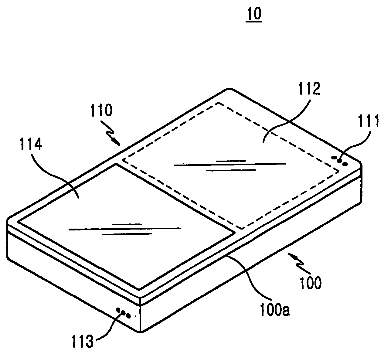
图1是根据本发明第一实施例的直板式便携式通信终端的透视图;1 is a perspective view of a bar type portable communication terminal according to a first embodiment of the present invention;
图2是当光源照亮光学单元时图1显示的终端的侧视图;Figure 2 is a side view of the terminal shown in Figure 1 when a light source illuminates the optical unit;
图3是根据本发明第二实施例的滑动式便携式通信终端的透视图;3 is a perspective view of a slide type portable communication terminal according to a second embodiment of the present invention;
图4是当显示单元完全滑动时根据本发明第二实施例的终端的透视图;4 is a perspective view of a terminal according to a second embodiment of the present invention when the display unit is fully slid;
图5是图4所示的终端的主视图,其中,所述终端具有安装于其中的光学单元;FIG. 5 is a front view of the terminal shown in FIG. 4, wherein the terminal has an optical unit installed therein;
图6是当光学单元将源图像发射到显示单元时图4所示的终端的侧视图;6 is a side view of the terminal shown in FIG. 4 when the optical unit transmits the source image to the display unit;
图7是根据本发明第三实施例的摆转式便携式通信终端的透视图;7 is a perspective view of a swing-type portable communication terminal according to a third embodiment of the present invention;
图8是当显示单元摆转大约90°时,根据本发明第三实施例的终端的透视图;FIG. 8 is a perspective view of a terminal according to a third embodiment of the present invention when the display unit is rotated about 90°;
图9是当顺着箭头A观看时,图8所示的终端的主视图;FIG. 9 is a front view of the terminal shown in FIG. 8 when viewed along arrow A;
图10是当顺着箭头B观看时,图8所示的终端的主视图;FIG. 10 is a front view of the terminal shown in FIG. 8 when viewed along arrow B;
图11是当显示单元摆转大约180°时,根据本发明第三实施例的终端的透视图;FIG. 11 is a perspective view of a terminal according to a third embodiment of the present invention when the display unit is rotated about 180°;
图12是当光学单元将源图像发射到显示单元时图11所示的终端的侧视图;12 is a side view of the terminal shown in FIG. 11 when the optical unit emits the source image to the display unit;
图13显示了根据本发明的便携式通信终端使用的光学单元的简单结构。FIG. 13 shows a simple structure of an optical unit used in a portable communication terminal according to the present invention.
具体实施方式 Detailed ways
以下,将参照附图详细地描述本发明的实施例。在以下对本发明的描述中,将省略对包含于此的公知功能和构造的详细描述,从而避免使得本发明的主题内容不清楚。Hereinafter, embodiments of the present invention will be described in detail with reference to the accompanying drawings. In the following description of the present invention, a detailed description of well-known functions and constructions incorporated herein will be omitted so as not to obscure the subject matter of the present invention.
参照图1和图2,根据本发明第一实施例的直板式便携式通信终端使用平板式波导管(panel-type waveguide)110作为其数据输出装置。更具体地说,终端10包括主体100、安装在主体100上用于显示数据的平板式波导管110以及布置在平板式波导管110上的信息输入/输出装置114。平板式波导管110作为用于引导源图像以将其直观地显示的数据输出装置。被引导的源图像被二维地显示在平板式波导管110上,平板式波导管110最好由透明材料形成为一个整体。1 and 2, a bar-type portable communication terminal according to a first embodiment of the present invention uses a panel-
主体100呈直板状并且包括光学单元120,对光学单元120的详细描述将在随后进行。平板式波导管110具有面对主体100的上表面100a的用于显示被光学单元120发射的源图像的显示单元112。信息输入/输出装置114作为单独的单元被布置为与平板式波导管110(尤其是与显示单元112)平行,同时靠近显示单元112。The
信息输入/输出装置114可由基于用户的触摸操作输入期望的数据和输出被输入的数据的触摸屏或者触摸感应面板(touch-sensitive panel)构成。The information input/
平板式波导管110的形状与主体100的形状对应,并且安装在主体100上盖住上表面100a。如上所述,显示单元112和信息输入/输出装置114分别被布置在主体100的上部和下部。考虑到用户的耳和嘴之间的距离,扬声器111和麦克风113分别被设置成靠近平板式波导管110上端和主体100的下端。主体100具有布置在其底表面上的电池包(未示出)。The
当光学单元120发射源图像时,对应的图像被显示在屏幕(即,显示单元112)上。When the
参照图3至图6,将描述根据本发明第二实施例的便携式通信终端20的构造。如图3至图6所示,终端20使用适于滑动的平板式波导管210作为终端的数据输出装置。尤其是,终端20包括主体200、安装在主体200上的平板式波导管210和安装在平板式波导管210上的光学单元220,其中,平板式波导管210沿着主体200的纵向滑动并且用于显示数据,光学单元220在被容纳在主体200中的同时运动并且为平板式波导管210提供源图像。平板式波导管210作为用于引导源图像的数据输出装置,以使得源图像被直观地显示。被引导的源图像被二维地显示在平板式波导管210上,平板式波导管210最好由透明材料形成为一个整体。平板式波导管210适于在滑动的同时持续面对主体200的上表面200a并且暴露/覆盖主体200的预定区域。3 to 6, the configuration of a
主体200呈直板状。主体200具有布置在其上表面200a上的用户接口(user-interface)单元(例如,键202的阵列),其布置方式是,根据平板式波导管210是否滑动,用户接口单元被暴露/覆盖。光学单元220被布置在键202之下并且适于与平板式波导管210一起运动。用户接口单元由键202的阵列(例如,3×4阵列)组成,所述键202的阵列被按下以输入期望的数据。平板式波导管210具有面对主体200的上表面200a的用于显示由光学单元220发射的源图像的显示单元212。显示单元212覆盖平板式波导管210的至少一半的区域。The
平板式波导管210的形状与主体200的形状对应,并且平板式波导管210足够大以完全覆盖住主体200的上表面200a。图3显示了当主体200被完全覆盖住时的平板式波导管210,图4显示了当主体200被充分暴露时的平板式波导管210。The shape of the
光学单元220通过连接器222和224结合到平板式波导管210,连接器222和224与平板式波导管210作为单一的单元一起运动。当平板式波导管210充分远离主体200时,平板式波导管210引导来自光学单元220的源图像并且显示它们。
在图4中,标号204和206代表导向开口,连接器222和224在所述导向开口中运动。In FIG. 4,
现在,参照图7至图12,将描述根据本发明第三实施例的便携式通信终端30的构造。如图7至图12所示,终端30使用适于摆转的平板式波导管作为数据输出装置。具体地说,终端30包括主体300、安装在主体300上的平板式波导管310和一体地安装在平板式波导管310上的光学单元320,其中,平板式波导管310可摆转和显示数据,光学单元320在被容纳在主体300中的同时运动并且为平板式波导管310提供源图像。平板式波导管310作为用于引导源图像使得它们被直观地显示的数据输出装置。被引导的源图像被二维地显示在平板式波导管310上。Now, referring to FIGS. 7 to 12, the configuration of a
平板式波导管310具有面对主体300的上表面300a的显示单元312(即,显示单元312被布置为与所述上表面平行),所述平板式波导管310用于显示通过光学单元320发射的源图像。The
主体300呈直板状。主体300具有布置于其上表面300a上的用户接口单元(例如,键302的阵列),其布置方式是,根据平板式波导管310是否滑动,用户接口单元被暴露/覆盖。光学单元320被布置在键302之下并且适于与平板式波导管310一起运动。用户接口单元由键302的阵列(例如,3×4阵列)组成,所述键302的阵列被按下以输入期望的数据。平板式波导管310具有面对主体300的上表面300a的用于显示由光学单元320发射的源图像的显示单元312。显示单元312覆盖平板式波导管310的至少一半的区域。The
平板式波导管310的形状与主体300的形状对应,并且平板式波导管310足够大以完全覆盖住主体300的上表面300a。图7显示了当主体300被平板式波导管310完全覆盖住时的平板式波导管310,图8显示了当平板式波导管310摆转90°并且垂直于主体300时的平板式波导管310,图11显示了当平板式波导管310摆转180°并且平行于主体300的纵向时的平板式波导管310。主体300上的键302根据平板式波导管310是否摆转而被暴露/覆盖。具体地说,当平板式波导管310摆转大约90°或180°时,键302被完全暴露。The shape of the
光学单元320通过连接器322和324结合到平板式波导管310,连接器322和324与平板式波导管310作为单一的单元一起运动。当平板式波导管310充分远离主体300时,平板式波导管310引导来自光学单元320的源图像并且显示它们。Optical unit 320 is coupled to
参照图13,根据本发明的便携式通信终端使用的光学单元40包括作为微型投影器的图像源单元410、镜子412和透镜系统414。图像源单元410发射源图像,该源图像的路径通过镜子412被改变。在被镜子412反射之后,图像在经过透镜系统414时被漫射。经过透镜系统被漫射的图像被发射到平板式波导管420上。镜子412或透镜系统414可以是固定的也可以是可旋转的,使得被漫射的图像可沿着期望的方向传播。图像源单元410可包括传统的光源和微LCD。在这种情况下,微LCD用于显示作为由光源发射的源图像的图像。Referring to FIG. 13 , an optical unit 40 used in a portable communication terminal according to the present invention includes an
虽然在以上描述中假设根据本发明的平板式波导管被用作二维地显示由光学单元发射的源图像的屏幕,但是可用三维全息屏幕来代替平板式波导管,以使得被光学单元发射的源图像被三维地显示在与全息屏幕隔开预定距离的平面上。Although it has been assumed in the above description that the slab waveguide according to the present invention is used as a screen for two-dimensionally displaying the source image emitted by the optical unit, a three-dimensional holographic screen can be used instead of the slab waveguide so that the slab waveguide emitted by the optical unit The source image is three-dimensionally displayed on a plane spaced a predetermined distance from the holographic screen.
虽然已经参照本发明的特定优选实施例显示并描述了本发明,但是本领域技术人员应该理解,在不脱离由权利要求限定的本发明的精神和范围的情况下,可在此做出形式和细节上的各种改变。While the invention has been shown and described with reference to certain preferred embodiments thereof, it will be understood by those skilled in the art that changes may be made therein in form and without departing from the spirit and scope of the invention as defined by the claims. Various changes in details.
Claims (10)
Applications Claiming Priority (2)
| Application Number | Priority Date | Filing Date | Title |
|---|---|---|---|
| KR1020060076122 | 2006-08-11 | ||
| KR1020060076122A KR100762671B1 (en) | 2006-08-11 | 2006-08-11 | Portable communication terminal having a display unit using a light receiving panel |
Publications (1)
| Publication Number | Publication Date |
|---|---|
| CN101123776A true CN101123776A (en) | 2008-02-13 |
Family
ID=38561565
Family Applications (1)
| Application Number | Title | Priority Date | Filing Date |
|---|---|---|---|
| CNA2007101403014A Pending CN101123776A (en) | 2006-08-11 | 2007-08-08 | Portable communication terminal with display unit using planar waveguide |
Country Status (5)
| Country | Link |
|---|---|
| US (1) | US20080039151A1 (en) |
| EP (1) | EP1887764B1 (en) |
| KR (1) | KR100762671B1 (en) |
| CN (1) | CN101123776A (en) |
| DE (1) | DE602007001312D1 (en) |
Families Citing this family (17)
| Publication number | Priority date | Publication date | Assignee | Title |
|---|---|---|---|---|
| USD582878S1 (en) * | 2007-06-18 | 2008-12-16 | Panasonic Corporation | Mobile phone |
| USD577350S1 (en) * | 2007-08-10 | 2008-09-23 | Samsung Electronics Co., Ltd. | Mobile phone |
| USD577353S1 (en) * | 2007-10-16 | 2008-09-23 | Samsung Electronics Co., Ltd. | Mobile phone |
| USD575259S1 (en) * | 2007-10-16 | 2008-08-19 | Samsung Electronics Co., Ltd. | Mobile phone |
| US8150482B2 (en) * | 2008-01-08 | 2012-04-03 | Hewlett-Packard Development Company, L.P. | Mobile computing device with moveable housing segments |
| USD593525S1 (en) * | 2008-06-04 | 2009-06-02 | Hon Hai Precision Industry Co., Ltd. | Mobile phone |
| USD605157S1 (en) * | 2008-06-11 | 2009-12-01 | Lg Electronics Inc. | Cellular phone |
| USD622244S1 (en) * | 2009-05-13 | 2010-08-24 | Panasonic Corporation | Mobile phone |
| USD659131S1 (en) * | 2009-07-27 | 2012-05-08 | Sony Mobile Communications Japan, Inc. | Mobile phone |
| USD722035S1 (en) * | 2013-01-02 | 2015-02-03 | Samsung Display Co., Ltd. | Mobile phone |
| USD722036S1 (en) * | 2013-01-02 | 2015-02-03 | Samsung Display Co., Ltd. | Mobile phone |
| USD721671S1 (en) * | 2013-01-02 | 2015-01-27 | Samsung Display Co., Ltd. | Mobile phone |
| USD722037S1 (en) * | 2013-01-02 | 2015-02-03 | Samsung Display Co., Ltd. | Mobile phone |
| USD737794S1 (en) * | 2013-06-14 | 2015-09-01 | Lg Electronics Inc. | Mobile phone |
| USD737238S1 (en) * | 2013-06-14 | 2015-08-25 | Lg Electronics Inc. | Mobile phone |
| USD736172S1 (en) * | 2013-06-26 | 2015-08-11 | Isaac S. Daniel | Mobile communication device |
| USD735688S1 (en) * | 2013-06-26 | 2015-08-04 | Isaac S. Daniel | Mobile communication device |
Family Cites Families (9)
| Publication number | Priority date | Publication date | Assignee | Title |
|---|---|---|---|---|
| GB2308486A (en) | 1995-12-21 | 1997-06-25 | Nokia Mobile Phones Ltd | Display apparatus for hand held equipment |
| KR20000039641A (en) * | 1998-12-15 | 2000-07-05 | 윤종용 | Apparatus for displaying information in closed state of folder |
| KR20010068807A (en) | 2000-01-10 | 2001-07-23 | 윤종용 | Radiotelephone for visual communication |
| KR100436666B1 (en) * | 2001-12-14 | 2004-06-22 | 삼성전자주식회사 | Portable mobile phone with display unit using holographic screen |
| KR100484732B1 (en) * | 2002-11-19 | 2005-04-22 | 삼성전자주식회사 | Sliding type portable wireless terminal |
| JP3849694B2 (en) | 2004-04-27 | 2006-11-22 | 日本ビクター株式会社 | Optical wireless communication device |
| US7388578B2 (en) * | 2004-07-01 | 2008-06-17 | Nokia Corporation | Touch display PDA phone with slide keypad |
| KR100666196B1 (en) * | 2004-07-29 | 2007-01-09 | 크루셜텍 (주) | Optical pointing device and personal digital assistant |
| US20060146013A1 (en) | 2005-01-04 | 2006-07-06 | Arneson Theodore R | Electronic device with virtual image display |
-
2006
- 2006-08-11 KR KR1020060076122A patent/KR100762671B1/en not_active Expired - Fee Related
-
2007
- 2007-08-08 CN CNA2007101403014A patent/CN101123776A/en active Pending
- 2007-08-10 DE DE602007001312T patent/DE602007001312D1/en active Active
- 2007-08-10 EP EP07114156A patent/EP1887764B1/en not_active Not-in-force
- 2007-08-13 US US11/837,995 patent/US20080039151A1/en not_active Abandoned
Also Published As
| Publication number | Publication date |
|---|---|
| US20080039151A1 (en) | 2008-02-14 |
| DE602007001312D1 (en) | 2009-07-30 |
| KR100762671B1 (en) | 2007-10-01 |
| EP1887764A1 (en) | 2008-02-13 |
| EP1887764B1 (en) | 2009-06-17 |
Similar Documents
| Publication | Publication Date | Title |
|---|---|---|
| EP1887764B1 (en) | Portable communication terminal having display unit using panel-type waveguide | |
| KR100438433B1 (en) | Combination device with portable radiotelephone/personal digital assistant/digital camera assembly | |
| CN100492924C (en) | Portable terminal device using holographic screen for display unit | |
| CN100550923C (en) | Slide/Fold Portable Digital Communication Devices | |
| US7711397B2 (en) | Portable communication terminal for games and user interfacing device thereof | |
| KR100678041B1 (en) | Portable digital communication device with sliding / rotating hinge means | |
| US20070184882A1 (en) | Portable communication terminal for games | |
| CN1697334A (en) | Sliding/folding-type portable apparatus | |
| US7702096B2 (en) | Self-cradling type portable terminal | |
| EP1950937A2 (en) | Portable apparatus | |
| CN1997042A (en) | Mobile communication terminal having two keypads | |
| CN209419660U (en) | Electronic equipment | |
| US20070146977A1 (en) | Sliding and folding type portable terminal | |
| JP2004235687A (en) | Portable wireless terminal | |
| EP1777923A1 (en) | Portable terminal including a sliding and slanting housing carrying a display and loudspeakers | |
| KR20130006851A (en) | Camera device for portable terminal | |
| KR100735247B1 (en) | Magnetic Mounting Type Mobile Communication Device | |
| US7734314B2 (en) | Slim type portable terminal | |
| KR100754605B1 (en) | Mobile phone for game with folding-type keypad | |
| US20080068781A1 (en) | Portable electronic device | |
| KR100876790B1 (en) | Multimedia mobile communication device | |
| EP1594291B1 (en) | Sliding/folding-type portable apparatus | |
| KR100842528B1 (en) | Swing type mobile phone and swing device thereof | |
| KR100800753B1 (en) | Double-sided sliding type mobile terminal | |
| KR101612790B1 (en) | Portable terminal |
Legal Events
| Date | Code | Title | Description |
|---|---|---|---|
| C06 | Publication | ||
| PB01 | Publication | ||
| C10 | Entry into substantive examination | ||
| SE01 | Entry into force of request for substantive examination | ||
| C02 | Deemed withdrawal of patent application after publication (patent law 2001) | ||
| WD01 | Invention patent application deemed withdrawn after publication |
Open date: 20080213 |