Face mask support
The cross reference of related application
The present invention requires the rights and interests of following application according to the 119th e money of U.S.'s method 35 (35U.S.C. § 119 (e)): No. 60/404,685, the U.S. Provisional Application of submitting on August 20th, 2002; No. 10/643,642, the U.S. Patent application of submitting on August 19th, 2003 is No. 6,854,465, the United States Patent (USP) of authorizing on February 15th, 2005 now; No. 06/619,536, the U.S. Provisional Application of submitting on October 15th, 2004; And on February 12nd, 2005 No. 11/056,858, the U.S. Patent application submitted to.
Technical field
The present invention relates generally to the face mask support that Compressed Gas is provided for patient.This mask support can be connected to full facepiece mask or nose cup.This Compressed Gas can be surrounding air, oxygen or their mist.
Background technology
Along with the growth at people's age, air flue will reduce its opening owing to throat's muscle loses the muscle retractility, and this throat's muscle is generally used for preventing tissue influence's air flue.This situation is more serious in the patient of obesity, the air flue that they have born narrow air flue or may be hung down and partly to block by tonsillotome, soft palate or palate.When air is compelled to pass the air flue that narrows down under elevated pressure, the result of tissue vibration will be snoring.Snoring has destructiveness to sleep; The snorer not only made the companion can't fall asleep but also can repeatedly wake snorer oneself up at night.The disorder of this sleep can produce the tired weak sensation on daytime, and can reduce the performance of brain and body.In about 1/3rd snorer, this situation may be extremely harmful.When narrowing down of air flue developed into complete closure, this situation was called as sleep apnea.The backfeed loop of the inefficacy between brain and respiratory system makes air flue subside fully, recovers to breathe until brain prompting hypoxemia level and patient wake up suddenly.Can as per minute once this regular the starting up suddenly of frequent generation make the heart rate of heart rate picture on roller-coaster.For the patient of sensitivity, high heart rate can cause fatal arrhythmia cordis or miocardial infarction.
Continuation Positive Airway Pressure (CPAP) is a kind of method of using a period of time, be used for alleviating the symptom of snoring or sleep apnea, this method is by means of carrying air or gas under pressure, the retractility of throat's muscle made the effect of avoiding some or all of ground closed airway passage around the soft tissue of air flue when the enough imitations of this pressure normally woke.Patient except these have the patient of airway problems also can benefit from CPAP.These colonies comprise the myasthenic patient, the patient with traumatic neurotrosis or adult respiratory distress such as sequela of poliomyelitis or ALS of the breathing that air can not be sucked in the lung.The CPAP device is formed by the pressure fan that forced air stream or gas stream is provided, cover with the pipeline that cover is connected to blower source usually.Cover can all cover mouth and nose, only cover nose or have the connector that only inserts the nostril.Regardless of constructing, this cover bottom line must have the device that cover is sealed to face, so that the gas of pressure fan does not leak, thereby reduction is to the pressure of air flue.Must be provided for the steam vent of breath.Preferably, steam vent is arranged so that it avoids patient's eyes.Need mask support that cover and pipeline are remained on the appropriate location.
Compliance of patients is a problem normally.Operable most of covers are uncomfortable at present, are easy to be shifted or disconnect from blower source when sleep.If cover is full facepiece mask that nose and mouth are all covered or the nose cup that only covers nose, the edge of this cover will contact the bridge of the nose, go up or lower lip and must be around the cheek regional seal.Individual difference on facial pattern especially in the individual difference in zone, cheek, makes and must cover be remained on the face with certain pressure.Have been found that use semi-rigid internal support and flexible skirt can by air expand double-layer seal formed a kind of sealing that more is adapted to the zone, cheek.Full facepiece mask or nose cup that desirable mask support can be applicable to any type adapt to individual needs and hobby.
Mask support must be firmly held in the appropriate location to avoid exciting face with cover with as far as possible little pressure, particularly avoids stimulating the bridge of the nose.A kind of welcome design is included in the rigid strip that hangs on the center line of skull, and the blower source pipeline is arranged and fixing (United States Patent (USP) 1,081, No. 745 and 6,347, No. 631) along this belt simultaneously.This support member applies pressure to patient's point only at occipital bone and cover.
Still need a kind of comfortable face mask support, this face mask support is not exerted pressure and is not easy to the narrow zone of head or sensitizing range and moves or disconnect from its blower source.
Summary of the invention
A kind of mask support that is used for the continuation Positive Airway Pressure comprises: flexible cap and the blower source that is operably connected to this cap, this blower source is operably connected to cover.Preferably it has the pressure fan unit of outside by the pipeline that pressure fan is connected to cover of pitch of the laps support, interior smooth to this blower source.The following ring edge of this cap extends to by a bit the coming around head on the head center line that diameter limited of head from the occipital lobe to the forehead from the inion subordinate side of occipital bone.
This cap is roughly hemispheric and is made by light, flexible material.This ring edge is provided with the device that is used to tighten up.This device that tightens up can be elastic plugin, bracelet, draught line (draw strings) or the like, and perhaps these whole parts can be formed by elastomeric materials.Use elasticity and firm belt are strengthened the center line from the occipital lobe to the forehead.
The embodiment of open cap is made up of belt that limits ring edge and middle band, wherein should centre be with on the roughly center line of head by and locate to be connected to endless belt at the forehead place with in the inion subordinate side of occipital bone.This endless belt preferably is provided with the device that is used to adjust.This centre band can be divided into two parts above it is connected to the connector at endless belt rear portion.When this centre band was divided into two parts, every arm had been connected on the endless belt near the center line respectively.This endless belt and middle band can be constructed by the monoblock type material.
This centre band is equipped with the biasing device support member, and this biasing device support member extends to point near the skull summit along the centre band directly over the forehead connector of endless belt and middle band backward.This biasing device support member is that the bottom is bent the approximate wedge shape with the bending that adapts to skull, thereby end face becomes approximate right angle and provides stable location by rigidity or semi-rigid material structure for this biasing device with the vertical plane of face.This biasing device support member comprises that at least one is used to insert the groove of the end of biasing device.
This biasing device is by spring steel, spring or can not know that arbitrarily tired ground forms power from a metal or a constructed in plastic material that is delivered to another place.This biasing device preferably is configured as the spring steel of the continuous length of the ring and the transverse arm of two equal lengths, its each end can insert the biasing device support member, be parallel to the end face of this biasing device support member, and be bent into and become roughly 90 degree with the vertical plane of face.The extension one like this of this biasing device enough arrives the length in nose the place ahead, and forms the bendings of 90 degree so that be parallel to the vertical plane of face at this point.Descending transverse arm forms the ring of installing around the distal face of face shield.This mask support is suitable for full facepiece mask or nose cup remain on the appropriate location arbitrarily.This descending transverse arm also can be the spring steel of a discrete segment length, and each spring steel inserts biasing device and inserts in the face shield at its near-end or far-end independently.
The groove of this biasing device support member is provided with the end of the arm that is used to adjust biasing device and inserts the device of length, thereby adjusts biasing device level length forward.This adjusting device can be ratchet or friction keeper.This adjustment has adapted to individual facial differences and face shield has been remained on the appropriate location applied force.
The endless belt of open cap is adjustable in each side of head, and this adjustment can be passed through Velcro (Velcro), bracelet, press formula button or the like.Can provide less by the rope that has slip clamp and adjustment fast, this rope can be tightened up apace and discharge to adjust size lessly and apace.Middle band also can be provided for the device adjusted similarly in the back of head.When the centre band is divided into two parts, the device that the arm of each branch can be provided for adjusting.
Second embodiment comprises endless belt, stabilized zone and the biasing device of fixing by the biasing device support member.Band in the middle of this embodiment does not have.Point on the height of this endless belt under from the inion subordinate side of patient's occipital bone to patient's hairline comes around head.This endless belt is formed the inner substrate of semi-rigid outer substrate and the flexible material that contacts with patient skin or hair by flexible material.
This endless belt is provided with the device that is used to tighten up.This device that tightens up can be Velcro, elastic plugin, bracelet, draught line or the like.This device that tightens up can be incorporated in the belt, is connected to endless belt securely by the any-mode such as ultrasonic bonding or gummed.This endless belt is bent to S shape in the area just above of patient's ear.
The stabilized zone is crossed the pileum extension and is connected on the endless belt in the generally'S '-shaped knee of each side.The stabilized zone can be below this biasing device support member by or can be connected respectively to this biasing device support member.This connection can be by the any-mode such as ultrasonic bonding or gummed.Preferably, the biasing device support member is provided with ring in each side, and the stabilized zone is passed this ring by bracelet and connected, and perhaps the stabilized zone is passed this ring and made itself to curved and fix with Velcro.
The biasing device support member is that the bottom is bent approximate wedge shape with the bending that adapts to skull, and is formed by rigidity or semi-rigid material structure, thereby provides stable location for this biasing device.This biasing device support member extends towards pileum from the forehead region under patient's hairline, and this is connected on the endless belt securely at forehead foremost, and the rear end is connected on the stabilized zone.The biasing device support member preferably is provided with the mat lining, and this mat lining has makes the structure that some air circulation are arranged under this support member.
The biasing device support member comprises that at least one is used to insert the groove of the end of biasing device.Endless belt can have the extension that makes progress from the forehead region to the pileum, with the mat as the biasing device support member.Alternatively, the stabilized zone can be crossed pileum and extended continuously, and can and directly locate biasing device on the endless belt in the place ahead, stabilized zone at pileum place on the stabilized zone, and wherein this endless belt and stabilized zone are as mat.
Biasing device is by spring steel, spring or can not know that arbitrarily tired ground forms power from a metal or a constructed in plastic material that is delivered to another place.Biasing device can form with multiple structure, and the end of this biasing device can insert in the holding tank on the biasing device support member, is parallel to the end face of this biasing device support member.Biasing device extension one enough arrives the length in nose the place ahead, and forms the bendings of 90 degree so that be parallel to the vertical plane of face at this point.Descending transverse arm is around the cover or install above cover.Mask support is suitable for full facepiece mask or nose cup remain on the appropriate location arbitrarily.
In any configuration of biasing device, the mechanism of horizontal location in the biasing device support member is installed, on the horizontal length of biasing device so that outwards adjust this mask support from face.Equally, this descending arm is equipped with the mechanism that is used to locate air chamber, so that adjust cover vertically.Preferred adjusting device is a ratchet, and it has and is installed in the gentle indoor corresponding ratchet of biasing device support member respectively.
When face shield was full facepiece mask, biasing device connected or centers on the far-end connection of this face shield at the far-end of this face shield.When face shield was nose cup, biasing device connected at this nose cup place or connects above this nose cup.Preferably, the face mask support that uses with nose cup comprises: air chamber, at least one hole or the preferred a plurality of steam vent that make the jockey of the work that cooperatively interacts between air hose and the nose cup and be used for breath.This steam vent preferred arrangements is at the end face of air chamber, so that the guiding breath leaves patient.
In arbitrary embodiment, mask support is made by softness, flexible material, and the biasing device support member is to be made by the bigger material of rigidity, and biasing device is to be made by very firm material.Preferably, endless belt and stabilized zone are made of two layers of substrate.Outer substrate is enough hard preventing that belt from rolling, and the inner substrate that contacts with patient skin, hair and scalp is soft and can have structure such as circular protrusions to allow some air circulation under support member.
When mask support is made by elastomeric material, can remove the device that is used to adjust.Those of ordinary skills easily alternate material obtain identical or essentially identical support member.These materials are considered within the scope of the appended claims.
Description of drawings
Fig. 1 shows the side view of opening the hat type mask support of the present invention.
Fig. 2 shows the vertical view of mask support of the present invention.
Fig. 3 shows the front view of mask support of the present invention.
Fig. 4 shows the force vector of the preferred embodiment of mask support of the present invention.
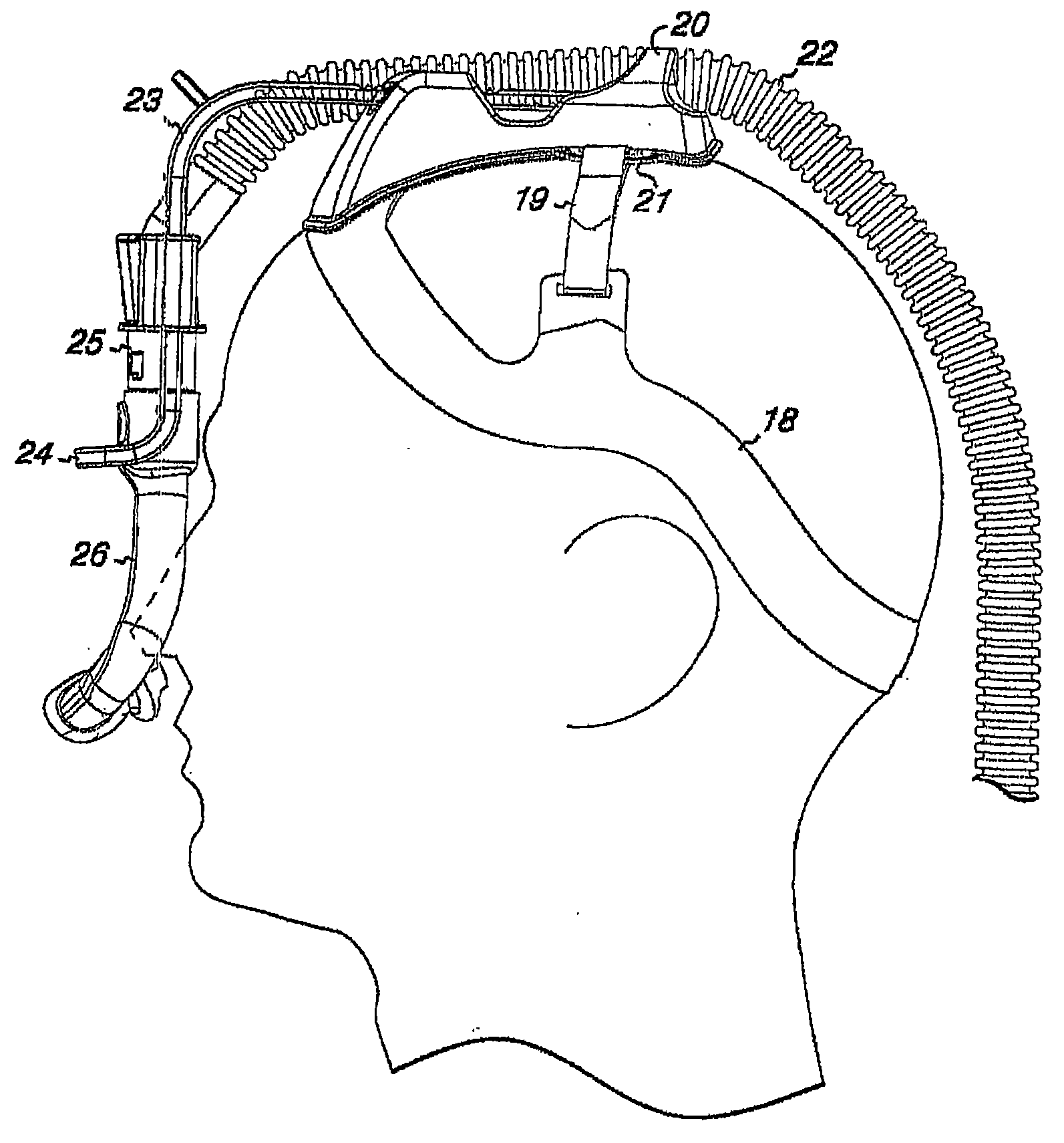
Fig. 5 shows the side view of the mask support of the present invention that nose cup is installed.
Fig. 6 shows the side view of the mask support of the present invention that face shield is installed.
Fig. 7 shows the vertical view of the present invention that nose cup is installed and has the biasing device support cushion.
Fig. 8 is the decomposition view of molded strip.Fig. 8 A shows upward view; Fig. 8 B shows vertical view.
Fig. 9 A shows the biasing device that air chamber is installed on it.Fig. 9 B shows the decomposition view of same device.
Figure 10 shows the single insert of the biasing device that inserts air chamber.
Figure 11 shows the biasing device support member with the holding tank that is used for the single arm type biasing device.
Figure 12 shows with the fixing biasing device of belt.
Figure 13 shows two biasing device support members.
Figure 14 shows the biasing device of being made up of two separation members.
The specific embodiment
When using in this application, following term has following implication:
" air " is used in reference to the gas that generation is transported to patient, comprises atmospheric gas, oxygen or their combination.
" pileum " refers to such an extent that be the perpendicular head zone afterwards of forehead, i.e. Tou top.
" hairline " refers to the highest region territory of forehead, and whether no matter hair arranged.
" face shield or full facepiece mask " refers to the cover that the periphery that covers patient's nose and all covers is applied to face.
" nose cup " refers to the cover that only is administered to the patient nostril.
" use " to refer to a surface pressure is come on another surface.
Target of the present invention is to provide has simultaneously in light weight, the comfortable CPAP mask support of reliable stability.The mask support formula face shield that is used for CPAP must keep being administered to face so that sealing to be provided with enough strength, do not leak in a large number so that air pressure can be applied directly to patient airway.This power can pass belt or as the biasing device described in common pending application patent application serial numbers 10/643,642, the content of these instructions is incorporated herein by reference.
In order to describe the present invention, use " face shield " or " cover " to comprise any device that is used for positive air pressure system (pressure fan) is connected to patient airway.Face shield can be the cover that covers whole face, cover the cover of nose and mouth, only cover the cover or the nasal obstruction of nose.Face mask support is to keep face shield to be administered to any device of face.
Example 1 first embodiment
Referring to Fig. 1, can see that the ring edge 1 of open cap is avoided responsive eyes and eyebrow zone, extend to the below (nape portion) of the inion portion of occipital bone from the forehead middle part.The ring edge of the open cap or the cap of remaining silent is depicted hemisphere as.Because it is head " low spot " that spine connects the nape place of head, belt passing round will tend to lean at that point arbitrarily, and the mask support cap of orientating as of this nature provides stability.Thereby, similarly as seen replacing forehead and occipital bone fixing point (referring to for example the 6th, 515, No. 802 United States Patent (USP)s) usually on the device with endless belt.Different with the support member among the U.S. Patent application US 2002/0117177 is that utilization applies the load of the load that is independent of facial sealing and endless belt is remained on the head.The edge of endless belt 1 is with on 2 in the middle of the rear portion of forehead and head is connected to.Because headband is clamped fully, middle band is provided with fully makes it be used as the stable support of biasing device support member.Because middle band is arranged on the center line of head, biasing device can produce and keep cover to be administered to moment on the needed counter clockwise direction of face, convert power the clockwise moment of cover load force to, produce leakage on the face and not thereby help cover remained on.Two arms of biasing device 3 are inserted into rigidity or semirigid biasing device support member 4 and circularize around face shield 5.Endless belt 1 is equipped with adjusting device 6 and rapid adjustment size rope (quick-sizing cord) 7.
With reference to Fig. 2, visible endless belt 1 is avoided responsive eyes and eyebrow zone, from the middle part of forehead extend to occipital bone inion portion below (nape portion).Because it is head " low spot " that spine connects the nape place of head, belt passing round will tend to lean at that point arbitrarily, and the mask support cap of orientating as of this nature provides stability.Endless belt 1 is with on 2 in the middle of the rear portion of forehead and head is connected to.Two arms of biasing device 3 are inserted into rigidity or semirigid biasing device support member 4 and circularize around face shield 5.
With reference to Fig. 3, the front view of mask support, the ring of biasing device are shown as around the distal face of face shield 5 and install.The adjustment part 8 that is used for biasing device 3 can be ratchet or rubbing device.Air duct 9 passes the groove that the ring by biasing device forms.Air duct 9 can be fixed on the biasing device at 10 places, be fixed on the biasing device support member, or be with in the middle of being fixed at 11 places.According to patient's hobby, air duct can freely rotate in the arbitrfary point, though most patient prefers using on the biasing device support member connector 10 to come the limit air pipeline to move.
The distribution of the power when Fig. 4 shows mask support is applied to head, wherein this mask support is connected to face shield 3 and blower system, and this power is to keep this face shield to be administered to the required power of face.This power is delivered to face shield via biasing device 3 from the crown.It should be noted that this power will change along with patient's difference.These variable factors comprise:
-maintenance patient's the required higher or lower positive air pressure of airway open;
-breathe enough air-flows that auxiliary patient provides for needs;
-tend to remove the more irritated patient of nose device (nose-piece);
-adapt to patient's personal like.
-or the unusual topology of patient face.By shortening or increase every one arm of biasing device, can increase or reduce biasing force at 8 places.
As already mentioned, the load that applies to endless belt is independent of the load that is used for face shield.Power vowed 13 before the power arrow that is produced in tightening up this endless belt comprised main back power arrow 12 and master, and each in these two power arrows is perpendicular to head surface.Decomposing force X14 that should make a concerted effort and Y15 show " clamping " of head and how to finish.Notice is vowed X and Y, can see, when the crossing the high position and contact of ring edge and forehead and since " the following shear force " that effectively is not used to clamp and preceding power arrow X with non-resistance nonrigid belt is come off from the head backward, so clamping will be lost efficacy.Equally, if belt contacts with the high position of crossing of inion portion, back power vows that Y will be less than the following shear force that it is stoped so, and this flexibility band will come off forward from the head.In case cap is fully clamped by the suitable location of domed profiles, the middle stable anchor zone 16 of being with on the center line that just is maintained at head and being formed for connecting the biasing device support member.Use the rigidity or the semi-rigid material of short length to constitute the biasing device support member by the centre with the large-scale stability permission of formed fixed area.It should be noted that biasing device support member and biasing device are the only non-softness of mask support and parts inflexibility.
By means of this flexibility and stable structure, this biasing device can produce and keep cover to be administered to required on the face anticlockwise moment, power is converted to moment on the clockwise direction of cover load force, produce the load force of leaking and not being administered to little FX on the face and not thereby help cover remained on.
In use, patient adjusts cap to obtain " that unclamps is comfortable " and cap is placed on the his or her head by adjusting device 6, from the nape to the forehead cap is located.Patient uses rapid adjustment size rope 7 (being provided with in the embodiment of rapid adjustment size device at those) tractive cap to post head then.For this centre band of suitable assembling is adjustable.After having worn cap, will be connected to face shield from the air duct of pressure fan, so that centering on the far-end protuberance of face shield, passes through on the ring of biasing device.Bias terminal is installed in the groove of biasing device support member, adjusts length 1 to be adapted to the nose device is administered to the variation of the required on the face biasing force of patient.In case carried out initial adjustment, this biasing device just is connected on the mask support.Except the biasing device and biasing device support member that rest on patient head from forehead top to the skull top, this mask support is whole soft and flexible, forehead top is compared with eye areas with preceding pars subfrontalis sulci cinguli to the zone at skull top, is more insensitive for pressure.Obtain comfortable firm CPAP device thus, and improved compliance of patients.
Example 2 second embodiments
Face mask support in the example 1 is comfortable and firm.When keeping providing the clutch features of the stability shown in Fig. 4, manage to improve this design, make more comfortable support part with further weight reduction with the contact area of patient head.
Fig. 5 shows side view of the present invention, has the next endless belt 18 around head of inion portion from the forehead under patient's hairline to occipital bone.Compare with the endless belt in first embodiment, endless belt in this embodiment is designed to be positioned at the more eminence of patient's forehead, makes belt pass through near ear.Therefore, avoiding contacting near the bending of the S shape on the height of ear with the excitant of ear.Stabilized zone 19 extends up to pileum from the zone near the bending of S shape.Biasing device support member 20 is positioned as from endless belt and extends to the stabilized zone.The biasing device support member can rest on the mat 21.Airway tube 22 is extended and 23 is extended downwardly into air chamber (plenum) 25 and nose cup 26 ring 24 on every side from this along biasing device along the end face of biasing device support member.In this preferred embodiment, the air chamber that is used to receive and discharge air is positioned in biasing device; And the ring of this biasing device passes through around air chamber, rather than passes through around the nose cup assembly.Because this preferred nose cup is to be fixed to patient's nostril lightly and is lightweight that this provides enough applied force.
Fig. 6 shows side view of the present invention, has the next endless belt 18 around head of inion portion from patient's forehead to occipital bone.Avoiding contacting near the bending of the S shape on the height of ear with the excitant of ear.Stabilized zone 19 extends up to pileum from the zone near the bending of S shape.Biasing device support member 20 is positioned as from endless belt and extends to the stabilized zone.This biasing device support member can rest on the mat 21.Airway tube 22 is extended and 23 is extended downwardly into air chamber 25 and face shield 26 ring 24 on every side from this along biasing device along the end face of this biasing device support member.In this embodiment, the air chamber that is used to receive and discharge air can be positioned in biasing device, and the ring of this biasing device passes through around the cover assembly.Provide like this than the bigger applied force of assembly of using this preferred nose cup, because bigger and heavier face shield needs bigger applied force that it is remained on the appropriate location.
Fig. 7 shows vertical view of the present invention, has the next endless belt 18 around head of inion portion from the forehead under patient's hairline to occipital bone.Avoiding contacting near the bending of the S shape on the height of ear with the excitant of ear.Stabilized zone 19 is connected on the endless belt and from extending up to pileum at the endless belt near the zone of S shape bending.Biasing device support member 21 is positioned as from endless belt and extends to the stabilized zone and be connected to the stabilized zone by the connector 28 on each side on this biasing device support member.This biasing device support member can rest on the mat 21 and be provided with holding tank 27A and 27B.Airway tube 22 is extended and 23 is extended downwardly into around the ring 24 of the air chamber 25 of nose cup 26 tops from this along biasing device along the end face of this biasing device support member.In this preferred embodiment, the air chamber that is used to receive and discharge air is positioned in biasing device; And the ring of this biasing device passes through around air chamber, rather than passes through around the nose cup assembly.
Fig. 8 A shows the molded circumferential band of expansion, and wherein biasing device support member 20 is positioned on endless belt 18 and the mat 21.When assembling, the end of endless belt 18 is by sonic welding or glue together fixed to one another connecting together, but preferably connects together by adjusting device, and these adjusting devices can be bracelets, by formula button or Velcro preferably.Stabilized zone 19 generally is conveniently molded as tongues of the circumferential band 18.Can be on the biasing device support member or the outer substrate in stabilized zone (substrate) the formed connected fitting 28 that comes up.Endless belt 18 and stabilized zone 19 be all by enough hard preventing that the outer substrate 29 that belt rolls from forming, and have the inner substrate that softer material 30 is made on a side of contact skin and/or hair.Belt can be made by the material of any suitable such as silicone/silicone foam or polyethylene/polyethylene foam.Fig. 8 B shows the vertical view of this molded strip, also shows holding tank 27A and 27B on biasing device support member 20.
Fig. 9 A shows biasing device 23, air chamber 25 with ratchet 31A and 31B and the ring 24 that centers on this air chamber.Fig. 5 B shows the exploded view of same parts.Ratchet 31A and 31B slide along the ratchet (not shown) of the correspondence in the biasing device support member, so that horizontal adjusting to be provided.Air chamber is connected to biasing device by spring 33, and the pipeline 34 (be shown as and cut open) at the top provides the connection of airway tube.Pipeline 32 passes air chamber and connects the connector that leads to nose cup or face shield.Steam vent 35 is positioned at the top of air chamber so that the air discharge of breathing out.Ratchet 36A on biasing device and 36B slide corresponding to the ratchet (not shown) in the air chamber, so that vertical adjustment to be provided.
Any one embodiment of the present invention provides and has kept nose cup or face shield to be administered on the face necessary power.This power is passed to nose or face via biasing device from the crown.It should be noted that this power can change along with patient's difference.These variable factors comprise:
-maintenance patient's the required higher or lower positive air pressure of airway open;
-arrive and need breathe enough air-flows of auxiliary patient;
-tend to remove the more irritated patient of cover;
-patient's personal like; Perhaps
The unusual topology of-patient face.
By the mask support light, that still less limit in biasing device, endless belt and stabilized zone with easy adjustment is provided, most patient can feel that the present invention is comfortable, and by the use of encouraging to comply with it.
The configuration of example 3 biasing devices
Though the configuration of the biasing device as shown in Fig. 5 to 9 is desirable, this configuration also can change.Figure 10 shows the biasing device 23 with two descending arms, among the holding tank 27A and 27B on this descending arm insertion biasing device support member 29.This two knee-joint synthesizes the descending arm of wall scroll, inserts in the air chamber.
Figure 11 shows biasing device support member 20, and this biasing device support member 20 has single holding tank 27 of the biasing device that is used for single arm type.
Figure 12 shows and passes the biasing device that holding tank 27A and 27B are inserted into biasing device support member 20.Every one arm by directly insert air chamber rather than by form around ring support air chamber.Belt 37 provides stability.
Figure 13 shows two biasing device support member 20A and 20B, and wherein every one arm of biasing device 23 passes holding tank 27A and inserts the biasing device support member that separates with 27B.
Figure 14 shows the biasing device that is formed by two separation member 23A and 23B structure.
It should be understood that in each of these biasing devices shown in Figure 10 to 14 all just like the device that is used for horizontal adjusting and vertically adjusts shown in Fig. 9 A and the 9B.
It should be understood that under the instruction of present patent application those of ordinary skills can easily carry out the conversion of unsubstantiality, these conversion should be considered within the spirit and scope of the present invention.