CN101155497A - Phase change cooling device and method - Google Patents
Phase change cooling device and method Download PDFInfo
- Publication number
- CN101155497A CN101155497A CN200610142190.6A CN200610142190A CN101155497A CN 101155497 A CN101155497 A CN 101155497A CN 200610142190 A CN200610142190 A CN 200610142190A CN 101155497 A CN101155497 A CN 101155497A
- Authority
- CN
- China
- Prior art keywords
- working fluid
- heat
- heat exchange
- exchange unit
- phase
- Prior art date
- Legal status (The legal status is an assumption and is not a legal conclusion. Google has not performed a legal analysis and makes no representation as to the accuracy of the status listed.)
- Pending
Links
Images


Classifications
-
- F—MECHANICAL ENGINEERING; LIGHTING; HEATING; WEAPONS; BLASTING
- F28—HEAT EXCHANGE IN GENERAL
- F28D—HEAT-EXCHANGE APPARATUS, NOT PROVIDED FOR IN ANOTHER SUBCLASS, IN WHICH THE HEAT-EXCHANGE MEDIA DO NOT COME INTO DIRECT CONTACT
- F28D1/00—Heat-exchange apparatus having stationary conduit assemblies for one heat-exchange medium only, the media being in contact with different sides of the conduit wall, in which the other heat-exchange medium is a large body of fluid, e.g. domestic or motor car radiators
- F28D1/02—Heat-exchange apparatus having stationary conduit assemblies for one heat-exchange medium only, the media being in contact with different sides of the conduit wall, in which the other heat-exchange medium is a large body of fluid, e.g. domestic or motor car radiators with heat-exchange conduits immersed in the body of fluid
- F28D1/0226—Heat-exchange apparatus having stationary conduit assemblies for one heat-exchange medium only, the media being in contact with different sides of the conduit wall, in which the other heat-exchange medium is a large body of fluid, e.g. domestic or motor car radiators with heat-exchange conduits immersed in the body of fluid with an intermediate heat-transfer medium, e.g. thermosiphon radiators
-
- F—MECHANICAL ENGINEERING; LIGHTING; HEATING; WEAPONS; BLASTING
- F28—HEAT EXCHANGE IN GENERAL
- F28D—HEAT-EXCHANGE APPARATUS, NOT PROVIDED FOR IN ANOTHER SUBCLASS, IN WHICH THE HEAT-EXCHANGE MEDIA DO NOT COME INTO DIRECT CONTACT
- F28D15/00—Heat-exchange apparatus with the intermediate heat-transfer medium in closed tubes passing into or through the conduit walls ; Heat-exchange apparatus employing intermediate heat-transfer medium or bodies
- F28D15/02—Heat-exchange apparatus with the intermediate heat-transfer medium in closed tubes passing into or through the conduit walls ; Heat-exchange apparatus employing intermediate heat-transfer medium or bodies in which the medium condenses and evaporates, e.g. heat pipes
- F28D15/0266—Heat-exchange apparatus with the intermediate heat-transfer medium in closed tubes passing into or through the conduit walls ; Heat-exchange apparatus employing intermediate heat-transfer medium or bodies in which the medium condenses and evaporates, e.g. heat pipes with separate evaporating and condensing chambers connected by at least one conduit; Loop-type heat pipes; with multiple or common evaporating or condensing chambers
-
- H—ELECTRICITY
- H10—SEMICONDUCTOR DEVICES; ELECTRIC SOLID-STATE DEVICES NOT OTHERWISE PROVIDED FOR
- H10W—GENERIC PACKAGES, INTERCONNECTIONS, CONNECTORS OR OTHER CONSTRUCTIONAL DETAILS OF DEVICES COVERED BY CLASS H10
- H10W40/00—Arrangements for thermal protection or thermal control
- H10W40/70—Fillings or auxiliary members in containers or in encapsulations for thermal protection or control
- H10W40/73—Fillings or auxiliary members in containers or in encapsulations for thermal protection or control for cooling by change of state
-
- F—MECHANICAL ENGINEERING; LIGHTING; HEATING; WEAPONS; BLASTING
- F28—HEAT EXCHANGE IN GENERAL
- F28D—HEAT-EXCHANGE APPARATUS, NOT PROVIDED FOR IN ANOTHER SUBCLASS, IN WHICH THE HEAT-EXCHANGE MEDIA DO NOT COME INTO DIRECT CONTACT
- F28D21/00—Heat-exchange apparatus not covered by any of the groups F28D1/00 - F28D20/00
- F28D2021/0019—Other heat exchangers for particular applications; Heat exchange systems not otherwise provided for
- F28D2021/0028—Other heat exchangers for particular applications; Heat exchange systems not otherwise provided for for cooling heat generating elements, e.g. for cooling electronic components or electric devices
- F28D2021/0031—Radiators for recooling a coolant of cooling systems
Landscapes
- Engineering & Computer Science (AREA)
- Physics & Mathematics (AREA)
- Thermal Sciences (AREA)
- Mechanical Engineering (AREA)
- General Engineering & Computer Science (AREA)
- Life Sciences & Earth Sciences (AREA)
- Sustainable Development (AREA)
- Cooling Or The Like Of Semiconductors Or Solid State Devices (AREA)
- Cooling Or The Like Of Electrical Apparatus (AREA)
Abstract
一种相变散热装置与方法,主要包含一个热交换单元、一个受热单元及一组管系。该热交换单元是与外界冷空气进行热交换,使进入的工作流体冷凝成液态。该受热单元是与一个热源接触且内部流通有工作流体,使工作流体吸收热能后气化成气态。该管系是连通该热交换单元与该受热单元形成密闭回路,可导引该热交换单元内由气态冷凝成液态的工作流体由高处向低处进入该腔体,及导引该受热单元内由液态气化成气态的工作流体向低浓度扩散至该热交换单元。借此,使前述液体-气体在相变化的过程中,以特有的物理特性自体循环流动,并大幅提升散热效果与散热效率。
A phase change heat dissipation device and method mainly includes a heat exchange unit, a heat receiving unit and a set of piping systems. The heat exchange unit performs heat exchange with external cold air, so that the incoming working fluid is condensed into a liquid state. The heating unit is in contact with a heat source and a working fluid circulates inside, so that the working fluid absorbs heat energy and then vaporizes into a gaseous state. The piping system is connected to the heat exchange unit and the heat receiving unit to form a closed circuit, which can guide the working fluid in the heat exchange unit from the gaseous state to the liquid state to enter the cavity from the high place to the low place, and guide the heat receiving unit The working fluid that is vaporized from liquid to gas diffuses to the heat exchange unit at a low concentration. Thereby, during the process of phase change, the above-mentioned liquid-gas circulates itself with its unique physical characteristics, and greatly improves the heat dissipation effect and heat dissipation efficiency.
Description
【技术领域】【Technical field】
本发明涉及一种散热装置与方法,特别是指一种能散发热能的相变散热装置与方法。The invention relates to a heat dissipation device and method, in particular to a phase change heat dissipation device and method capable of dissipating heat.
【背景技术】【Background technique】
参阅图1,以台湾公告第M295424号「具致冷晶片的水冷式散热系统」新型专利案为例,主要包含有一个散热器11、一片致冷晶片12、一个增压装置13、一个水冷头14、串连该散热器11、该致冷晶片12、该增压装置13与该水冷头14的三条输送管15、串连该散热器11与该水冷头14的一条回送管16,及一个风扇17。该散热器11是可与外界冷空气进行热交换。该增压装置13是一种加压马达或压缩机,可以使流体循环流动于前述输送管15与该回送管16。该水冷头14是与一热源2(如电脑的中央处理器,CPU)接触。该风扇17是可产生冷风吹向该散热器11。Referring to Fig. 1, take Taiwan Announcement No. M295424 "Water Cooling System with Cooling Chip" as an example, which mainly includes a
借此,当该增压装置13加压流体时,该水冷头14内的流体会吸收该热源2的热能,并循环至该热交换器11与外界冷空气进行热交换,达到降温的效果,如此周而复始,使该热源2达到散热的目的。但是,前述散热系统虽然可以达到散热的目的,然而,其却于实际使用时,乃存有以下缺失而亟待解决:In this way, when the pressurizing
1.由于前述水冷式的散热系统必须依赖该增压装置13加压流体,才能使流体循环流动,不但元件较多、成本较高、噪音值高,且在增压同时也会产生热能,造成流体温度不断提高,而增加冷却负荷。1. Since the aforementioned water-cooled heat dissipation system must rely on the
2.重要的是,流体虽然可以借由热能的传导,吸收该热源2的热能,达到降温的目的,但是,流体的散热效率远不及气体分子,因此,在热传面积有限,且长时间使用后,该热源2与流体的温度会随时间增长而提高,严重影响散热效果。2. The important thing is that although the fluid can absorb the heat energy of the
3.再者,若前述流体是水,则在寒带地区气温达到0℃以下时,水会结冰,使装置失效,另一严重问题是,水如果有泄漏的情形,会使电子线路完全毁损,造成严重的损失。3. Furthermore, if the aforementioned fluid is water, the water will freeze when the temperature in the cold zone reaches below 0°C, causing the device to fail. Another serious problem is that if the water leaks, the electronic circuit will be completely damaged. , causing serious losses.
值得一提的是,虽然气体的散热效率较好,但是,目前主要是利用空气对流达到降温的目的,因此,散热的效果往往只在局限在该热源2的表面,而无法带走该热源2内部的热能,所以,整体而论,气体的散热效果反而不及水冷式散热系统。It is worth mentioning that although the heat dissipation efficiency of gas is relatively good, at present, air convection is mainly used to achieve the purpose of cooling down. Therefore, the heat dissipation effect is often limited to the surface of the
【发明内容】【Content of invention】
本发明的目的在于提供一种能降低噪音,并大幅提升散热效果与散热效率的相变散热装置与方法。The purpose of the present invention is to provide a phase change heat dissipation device and method that can reduce noise and greatly improve heat dissipation effect and heat dissipation efficiency.
本发明的特征在于:该相变散热装置是架置在至少一个热源上方,包含一个热交换单元、一个受热单元及一组管系。该热交换单元是与外界冷空气进行热交换,使进入的工作流体冷凝成液态。该受热单元是与该热源接触且内部流通有工作流体,使工作流体吸收热能后气化成气态。该管系是连通该热交换单元与该受热单元形成密闭回路,可导引该热交换单元内液态工作流体由高处向低处进入该腔体,及导引该受热单元内气态工作流体向低浓度扩散至该热交换单元。The feature of the present invention is that: the phase change heat dissipation device is installed above at least one heat source, and includes a heat exchange unit, a heat receiving unit and a set of piping systems. The heat exchange unit performs heat exchange with external cold air, so that the incoming working fluid is condensed into a liquid state. The heating unit is in contact with the heat source and a working fluid circulates inside, so that the working fluid absorbs heat energy and then vaporizes into a gaseous state. The piping system is connected to the heat exchange unit and the heat receiving unit to form a closed circuit, which can guide the liquid working fluid in the heat exchange unit to enter the cavity from a high place to a low place, and guide the gaseous working fluid in the heat receiving unit to The low concentration diffuses to the heat exchange unit.
本发明的特征在于:该相变散热方法包含下列步骤:The present invention is characterized in that: the phase change heat dissipation method comprises the following steps:
步骤一:使工作流体循环于一热交换空间与至少一热源间。Step 1: Make the working fluid circulate between a heat exchange space and at least one heat source.
步骤二:使工作流体在该热交换空间内冷凝成液态,并向下流经该热源。步骤三:使工作流体吸收热能后气化成气态,并向低浓度扩散至该热交换空间内。Step 2: Make the working fluid condense into a liquid state in the heat exchange space, and flow down through the heat source. Step 3: vaporize the working fluid into a gaseous state after absorbing heat energy, and diffuse into the heat exchange space at a low concentration.
本发明的功效是能借由气-液两相变化的工作流体,产生自体循环的流动效果,进而达到降低噪音、提升散热效果与散热效率的目的。The effect of the present invention is that the gas-liquid two-phase working fluid can generate the flow effect of self-circulation, thereby achieving the purpose of reducing noise, improving heat dissipation effect and heat dissipation efficiency.
【附图说明】【Description of drawings】
图1是一立体图,说明台湾专利号数第M295424号案。Fig. 1 is a perspective view illustrating Taiwan Patent No. M295424.
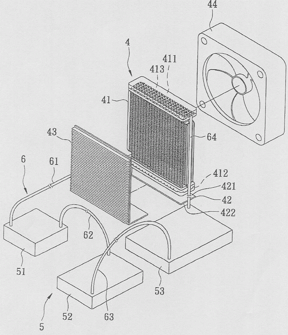
图2是本发明一相变散热装置与方法一第一较佳实施例的一立体图。FIG. 2 is a perspective view of a first preferred embodiment of a phase change heat dissipation device and method of the present invention.
图3是该第一较佳实施例的一部分剖视图。Fig. 3 is a partial sectional view of the first preferred embodiment.
图4是该第一较佳实施例安装在一个主机的一正视图。Fig. 4 is a front view of the first preferred embodiment installed in a host.
图5是该第一较佳实施例与该主机的一侧视图。Fig. 5 is a side view of the first preferred embodiment and the host.
图6是该第一较佳实施例的一流程图。Fig. 6 is a flowchart of the first preferred embodiment.
图7是本发明一相变散热装置与方法一第二较佳实施例的一立体图。7 is a perspective view of a second preferred embodiment of a phase change heat dissipation device and method of the present invention.
图8是本发明一相变散热装置与方法一第三较佳实施例的一配置示意图。FIG. 8 is a schematic configuration diagram of a third preferred embodiment of a phase change heat dissipation device and method of the present invention.
【具体实施方式】【Detailed ways】
下面结合附图及实施例对本发明进行详细说明。The present invention will be described in detail below in conjunction with the accompanying drawings and embodiments.
参阅图2、图3及图4,本发明的相变散热装置的一第一较佳实施例是安装于一个电脑主机3内,该主机3具有界定出一上容室31与一下容室32的一个机壳33、固设在该下容室32内的一块机板34,及设置在该机板34上的多个晶片模组35。该相变散热装置包含:一个热交换单元4、一个受热单元5及一组管系6。Referring to Fig. 2, Fig. 3 and Fig. 4, a first preferred embodiment of the phase-change cooling device of the present invention is installed in a computer mainframe 3, and this mainframe 3 has an upper chamber 31 and a lower chamber 32 defined A casing 33, a machine board 34 fixed in the lower chamber 32, and a plurality of chip modules 35 arranged on the machine board 34. The phase change heat dissipation device includes: a
该热交换单元4是设置在该主机3的上容室31内,并具有一个热交换器41、一致冷晶片组42、一个散热器43,及一个风扇44。该热交换器41具有形成在一顶面的一储气室411、形成在该一底面的一储液室412,及连通该储气室411与该储液室412的多条流道413。该致冷晶片组42是借由电路控制,具有维持低温状态且与该热交换器41储液室412接触的一冷端面421,及反向于该冷端面421的一热端面422,该冷端面421是具有冷冻作用,可以使该储液室412具有恒温效果。该散热器43大概呈L型,且与该致冷晶片组42的热端面421贴置并与该热交换器41平行并列。该风扇44是可产生冷风吹向该热交换器41与该散热器43。The
该受热单元5具有三个腔体51、52、53。前述腔体51、52、53是分别与热源温度低、中、高的晶片模组35接触。The
该管系6具有依序串连该热交换器41储液室412与该腔体51、该腔体51与该腔体52、该腔体52与该腔体53,及该腔体53与该热交换器41储气室411的四条串接管61、62、63、64,使前述串接管61~64与该热交换器41、前述腔体51~53形成一密闭回路。借此,在前述串接管61~64、前述腔体51~53与该热交换器41中抽取真空后,注入工作流体,使工作流体循环于一真空环境,工作流体在本实施例是一种在常温下为液态的冷媒,也可以是一种温度超传导液体。The
参阅图4、图5及图6,当该主机3开机后,前述晶片模组35即开始产生高温,以下即针对本发明相变散热方法说明如下:Referring to Fig. 4, Fig. 5 and Fig. 6, when the host computer 3 is turned on, the above-mentioned chip module 35 starts to generate high temperature, and the phase change heat dissipation method of the present invention is explained as follows:
步骤71:该腔体51内的工作流体会借由热传导吸收该晶片模组35(最低温)产生的热能,使部分液态工作流体气化成气态。Step 71: The working fluid in the
步骤72:该腔体51内的压力会提升,使气态工作流体随同液态工作流体经该串接管62进入该腔体52,此时,该腔体52内的液态工作流体会借由热传导吸收该晶片模组35(次低温)产生的热能,使部分液态工作流体气化成气态。Step 72: The pressure in the
步骤73:该腔体52内的压力会愈提升,使气态工作流体随同液态工作流体经该串接管63进入该腔体53,此时,该腔体53内的液态工作流体会借由热传导吸收该晶片模组35(最高温)产生的热能,使余下的液态工作流体气化成高温的气态工作流体。Step 73: The pressure in the
借此,前述腔体的串接数量可依前述晶片模组的数量而定,使工作流体由最低温到最高温依次流经前述腔体。In this way, the number of the cavities connected in series can be determined according to the number of the chip modules, so that the working fluid flows through the cavities sequentially from the lowest temperature to the highest temperature.
步骤74:高温的气态工作流体会依循该串接管64向低浓度扩散至该热交换器41的储气室411内。Step 74 : The high-temperature gaseous working fluid diffuses into the
步骤75:气体因为比重较重、压力、及地心引力的影响,开始沿前述流道413下坠,并与该热交换器41进行热交换,且该风扇44会产生冷风吹向该热交换器41与该散热器43,使该热交换器41、该散热器43与外界冷空气进行热交换。Step 75: The gas starts to fall along the
步骤76:高温的气态工作流体遇冷开始降温并凝结为水滴形成液态工作流体。Step 76: The high-temperature gaseous working fluid starts to cool down when it is cooled and condenses into water droplets to form a liquid working fluid.
步骤77:液态工作流体流入该热交换器41的储液室412内,受该致冷晶片组42冷端面421的冷冻作用,温度继续下降至预设值,而该致冷晶片组42热端面422会散发前述冷冻作用而产生的热能,并透过该散热器43与外界冷空气进行热交换,达到散热的效果。Step 77: The liquid working fluid flows into the
步骤78:由于流体具有由高向低流动的物理特性,因此,冷凝后的液态工作流体会由上向下,再次由该串接管61流入该腔体51内。Step 78: Since the fluid has a physical characteristic of flowing from high to low, the condensed liquid working fluid will flow from top to bottom and flow into the
重复步骤71~步骤78,如此周而复始,使前述工作流体在该热交换器4、前述腔体51~53与前述串接管61~64间自体循环,达到散热效果。Steps 71 to 78 are repeated, so that the aforementioned working fluid circulates itself among the
参阅图7,是本发明一第二较佳实施例,其与第一较佳实施例大致相同,不同处在于:Referring to Fig. 7, it is a second preferred embodiment of the present invention, which is substantially the same as the first preferred embodiment, except that:
该管系6具有连通该热交换器41储液室412的一个分流器65、分别连通该分流器65与前述腔体51~53且可导引工作流体进入前述腔体51~53内的三条并流液接管66、连通该热交换器41储气室411的一个汇流器67,及分别连通该汇流器67与前述腔体51~53且可导引气体进入该热交换器41储气室411的三条并流气接管68。The
在步骤78中,液态的工作流体是由该分流器65经前述并流接管66同时进入该腔体51~53内。借此,步骤71~步骤73是同步进行,也就是说,该液态的工作流体同样会吸收前述晶片模组35产生的热能并气化成气态工作流体,在步骤74中,高温的气态工作流体是由前述腔体51~53经前述并流气接管68汇集于该汇流器67,向低浓度扩散至该热交换器41的储气室411内,并依序进行步骤75~78。如此周而复始,使前述工作流体在该热交换器4、前述腔体51~53与该管系6间自体循环,达到散热效果。In step 78 , the working fluid in liquid state enters the cavities 51 - 53 simultaneously from the
参阅图8,是本发明一第三较佳实施例,其与第一、第二较佳实施例大致相同,不同处在于:Referring to Fig. 8, it is a third preferred embodiment of the present invention, which is substantially the same as the first and second preferred embodiments, except that:
本发明的热交换单元4可以透过该管系6以并连(或串连)的配置,与多个腔体54连通,而前述腔体54可以配合实务上应用的范畴,与各种会产生热源的电子元件7接触。以电脑主机为例,前述电子元件7可以是一种中央处理器、电源供应器、晶片模组、致冷晶片电源供应器….等。The
借此,本实施例的工作流体同样可以在前述液体-气体相变化的过程中,以特有的物理特性自体循环流动,并大幅提升散热效果与散热效率。In this way, the working fluid of this embodiment can also flow through its own body with its unique physical properties during the aforementioned liquid-gas phase change process, and greatly improve the heat dissipation effect and heat dissipation efficiency.
当然,本发明的相变散热装置与方法也可以扩充使用在汽车的引擎散热、或机械上的散热、或其他需要散热的装置。Of course, the phase-change heat dissipation device and method of the present invention can also be expanded and used in engine heat dissipation of automobiles, mechanical heat dissipation, or other devices that require heat dissipation.
据上所述可知,本发明的相变散热装置与方法具有下列优点及功效:According to the above, it can be seen that the phase change heat dissipation device and method of the present invention have the following advantages and effects:
1.本发明是借由前述液态-气态工作流体在二相变化的过程中,以液态工作流体由高处向低处流动,及气态工作流体由浓度高向浓度低流动的物理特性,产生自体循环的流动效果,不但可以简化元件、降低成本与噪音,且不会有额外的热源产生。1. The present invention is based on the physical characteristics of the aforementioned liquid-gaseous working fluid flowing from high to low and gaseous working fluid flowing from high concentration to low concentration during the two-phase change process to generate self-concentration. The circulating flow effect not only simplifies components, reduces cost and noise, but also does not generate additional heat sources.
2.重要的是,本发明可以借由液态工作流体以热传导的方式,有效吸收前述晶片模组35的热能,再变态为气态工作流体与该热交换单元4进行热交换,借此,不但能大幅提升散热效果与散热效率外,且本发明可以配合该致冷晶片组42以电控方式可编程控制温度,使该液态的工作流体不论时间长短,都可以维持在特定的温度范围,确保散热效果。2. The important thing is that the present invention can effectively absorb the heat energy of the aforementioned chip module 35 by way of heat conduction by the liquid working fluid, and then transform it into a gaseous working fluid for heat exchange with the
3.再者,本发明所使用的工作流体是冷媒或温度超传导液体,因此,在气温低于0℃时,不会有结冰的现象,可以保持工作时的顺畅性,且即使真空环境泄漏,工作流体也会瞬间气化,不会影响电子线路,能有效提升使用的实用件。3. Furthermore, the working fluid used in the present invention is a refrigerant or a temperature superconducting liquid, so when the temperature is lower than 0°C, there will be no freezing phenomenon, and the smoothness of work can be maintained, and even in a vacuum environment In case of leakage, the working fluid will also vaporize instantly, which will not affect the electronic circuit, and can effectively improve the practical parts used.
Claims (12)
Priority Applications (2)
| Application Number | Priority Date | Filing Date | Title |
|---|---|---|---|
| CN200610142190.6A CN101155497A (en) | 2006-09-29 | 2006-09-29 | Phase change cooling device and method |
| EP07251910A EP1909053A3 (en) | 2006-09-29 | 2007-05-09 | Heat dissipating system and method |
Applications Claiming Priority (1)
| Application Number | Priority Date | Filing Date | Title |
|---|---|---|---|
| CN200610142190.6A CN101155497A (en) | 2006-09-29 | 2006-09-29 | Phase change cooling device and method |
Publications (1)
| Publication Number | Publication Date |
|---|---|
| CN101155497A true CN101155497A (en) | 2008-04-02 |
Family
ID=38780800
Family Applications (1)
| Application Number | Title | Priority Date | Filing Date |
|---|---|---|---|
| CN200610142190.6A Pending CN101155497A (en) | 2006-09-29 | 2006-09-29 | Phase change cooling device and method |
Country Status (2)
| Country | Link |
|---|---|
| EP (1) | EP1909053A3 (en) |
| CN (1) | CN101155497A (en) |
Cited By (6)
| Publication number | Priority date | Publication date | Assignee | Title |
|---|---|---|---|---|
| CN102929366A (en) * | 2011-08-12 | 2013-02-13 | 英业达股份有限公司 | Cooling system |
| CN103105913A (en) * | 2011-11-14 | 2013-05-15 | 英业达股份有限公司 | Heat dissipation system |
| CN107577321A (en) * | 2017-10-26 | 2018-01-12 | 航天特种材料及工艺技术研究所 | A kind of radiator based on phase-change material |
| CN108781523A (en) * | 2015-12-29 | 2018-11-09 | 祖达科尔有限公司 | Heat management system based on vacuum |
| CN109584950A (en) * | 2018-12-29 | 2019-04-05 | 长兴旗滨玻璃有限公司 | Cooling system for instrument |
| CN114072628A (en) * | 2019-04-05 | 2022-02-18 | 相变能量解决方案有限公司 | Thermal management apparatus and method |
Families Citing this family (9)
| Publication number | Priority date | Publication date | Assignee | Title |
|---|---|---|---|---|
| CN102528409B (en) * | 2012-01-05 | 2014-07-16 | 华为技术有限公司 | Radiator of gravity loop heat pipe, condenser and manufacturing method thereof |
| US20130291555A1 (en) | 2012-05-07 | 2013-11-07 | Phononic Devices, Inc. | Thermoelectric refrigeration system control scheme for high efficiency performance |
| WO2013169774A2 (en) | 2012-05-07 | 2013-11-14 | Phononic Devices, Inc. | Thermoelectric heat exchanger component including protective heat spreading lid and optimal thermal interface resistance |
| US9593871B2 (en) | 2014-07-21 | 2017-03-14 | Phononic Devices, Inc. | Systems and methods for operating a thermoelectric module to increase efficiency |
| US10458683B2 (en) | 2014-07-21 | 2019-10-29 | Phononic, Inc. | Systems and methods for mitigating heat rejection limitations of a thermoelectric module |
| CN104669984B (en) * | 2015-02-13 | 2017-12-01 | 陈春平 | Vehicle-mounted LNG heat exchangers and the refrigerating transport vehicle for installing the heat exchanger |
| JP2020067226A (en) * | 2018-10-24 | 2020-04-30 | 株式会社デンソー | Temperature control device |
| CN111081665B (en) * | 2019-10-31 | 2024-11-26 | 长沙安牧泉智能科技有限公司 | A device for heat dissipation of multi-heat source devices |
| CN118524669A (en) * | 2023-02-20 | 2024-08-20 | 华为技术有限公司 | Heat dissipation system, electronic equipment and cabinet |
Family Cites Families (8)
| Publication number | Priority date | Publication date | Assignee | Title |
|---|---|---|---|---|
| US5343940A (en) * | 1992-10-29 | 1994-09-06 | Amigo Jean | Flexible heat transfer device |
| KR100338810B1 (en) * | 1999-11-08 | 2002-05-31 | 윤종용 | cooling device |
| US6474074B2 (en) * | 2000-11-30 | 2002-11-05 | International Business Machines Corporation | Apparatus for dense chip packaging using heat pipes and thermoelectric coolers |
| US6536510B2 (en) * | 2001-07-10 | 2003-03-25 | Thermal Corp. | Thermal bus for cabinets housing high power electronics equipment |
| US6704200B2 (en) * | 2002-02-12 | 2004-03-09 | Hewlett-Packard Development Company, L.P. | Loop thermosyphon using microchannel etched semiconductor die as evaporator |
| SE0301381D0 (en) * | 2003-05-12 | 2003-05-12 | Sapa Ab | Extruded heat sink with integrated thermosyphon |
| US7184265B2 (en) * | 2003-05-29 | 2007-02-27 | Lg Electronics Inc. | Cooling system for a portable computer |
| US6917522B1 (en) * | 2003-12-29 | 2005-07-12 | Intel Corporation | Apparatus and method for cooling integrated circuit devices |
-
2006
- 2006-09-29 CN CN200610142190.6A patent/CN101155497A/en active Pending
-
2007
- 2007-05-09 EP EP07251910A patent/EP1909053A3/en not_active Withdrawn
Cited By (8)
| Publication number | Priority date | Publication date | Assignee | Title |
|---|---|---|---|---|
| CN102929366A (en) * | 2011-08-12 | 2013-02-13 | 英业达股份有限公司 | Cooling system |
| CN103105913A (en) * | 2011-11-14 | 2013-05-15 | 英业达股份有限公司 | Heat dissipation system |
| CN108781523A (en) * | 2015-12-29 | 2018-11-09 | 祖达科尔有限公司 | Heat management system based on vacuum |
| CN107577321A (en) * | 2017-10-26 | 2018-01-12 | 航天特种材料及工艺技术研究所 | A kind of radiator based on phase-change material |
| CN107577321B (en) * | 2017-10-26 | 2023-09-29 | 航天特种材料及工艺技术研究所 | Radiator based on phase change material |
| CN109584950A (en) * | 2018-12-29 | 2019-04-05 | 长兴旗滨玻璃有限公司 | Cooling system for instrument |
| CN109584950B (en) * | 2018-12-29 | 2024-02-02 | 长兴旗滨玻璃有限公司 | Cooling system for instrument |
| CN114072628A (en) * | 2019-04-05 | 2022-02-18 | 相变能量解决方案有限公司 | Thermal management apparatus and method |
Also Published As
| Publication number | Publication date |
|---|---|
| EP1909053A2 (en) | 2008-04-09 |
| EP1909053A3 (en) | 2008-07-23 |
Similar Documents
| Publication | Publication Date | Title |
|---|---|---|
| CN101155497A (en) | Phase change cooling device and method | |
| TW200815968A (en) | Phase change heat dissipation device and method | |
| CN104930893B (en) | A kind of plate loop circuit heat pipe of ejector assist type | |
| TW200521657A (en) | Pumped liquid cooling system using a phase change refrigerant | |
| CN113825370A (en) | Refrigeration pump driving phase-change heat-cooling plate heat dissipation system and method combined with soaking plate | |
| CN102128517A (en) | Cooling and heat exchange device | |
| CN201119246Y (en) | Water-cooled auxiliary heat dissipation device | |
| CN101726136B (en) | Two-stage expansion cooling system and its evaporator | |
| TW200821801A (en) | Case having phase-change heat dissipating device | |
| Vuckovic et al. | Impacts of local cooling technologies on air cooled data center server performance: Test data analysis of Heatsink, Direct Liquid Cooling and passive 2-Phase Enhanced Air Cooling based on Loop Heat Pipe | |
| CN218414555U (en) | Refrigerating device for semiconductor equipment | |
| CN202217657U (en) | semiconductor chip refrigerating device | |
| CN112230741A (en) | A computer CPU cooling device | |
| CN205491621U (en) | Electronic equipment two -stage liquid refrigeration source system | |
| CN221551866U (en) | IGBT module cooling device | |
| CN213690434U (en) | Computer CPU cooling device | |
| CN220856565U (en) | Composite chip liquid cooling radiator | |
| CN213690433U (en) | Computer CPU cooling device | |
| CN200994245Y (en) | Phase transition radiating device | |
| CN2681218Y (en) | Liquid cooling type heat sink | |
| CN216218363U (en) | Refrigerating pump driving phase-change heat exchange cold plate heat dissipation system combined with vapor chamber | |
| CN201146659Y (en) | Water-cooled heat dissipation system | |
| CN112230740A (en) | A computer CPU cooling device | |
| WO2022141654A1 (en) | Electronic device heat dissipation apparatus having semiconductor auxiliary heat pump | |
| CN115143822B (en) | Loop heat pipe for enhancing internal circulation |
Legal Events
| Date | Code | Title | Description |
|---|---|---|---|
| C06 | Publication | ||
| PB01 | Publication | ||
| C10 | Entry into substantive examination | ||
| SE01 | Entry into force of request for substantive examination | ||
| C02 | Deemed withdrawal of patent application after publication (patent law 2001) | ||
| WD01 | Invention patent application deemed withdrawn after publication |
Open date: 20080402 |