CN101278552A - Image processing system and image processing program - Google Patents
Image processing system and image processing program Download PDFInfo
- Publication number
- CN101278552A CN101278552A CNA2006800363297A CN200680036329A CN101278552A CN 101278552 A CN101278552 A CN 101278552A CN A2006800363297 A CNA2006800363297 A CN A2006800363297A CN 200680036329 A CN200680036329 A CN 200680036329A CN 101278552 A CN101278552 A CN 101278552A
- Authority
- CN
- China
- Prior art keywords
- edge
- unit
- signal
- noise
- image processing
- Prior art date
- Legal status (The legal status is an assumption and is not a legal conclusion. Google has not performed a legal analysis and makes no representation as to the accuracy of the status listed.)
- Pending
Links
Images



Classifications
-
- H—ELECTRICITY
- H04—ELECTRIC COMMUNICATION TECHNIQUE
- H04N—PICTORIAL COMMUNICATION, e.g. TELEVISION
- H04N5/00—Details of television systems
- H04N5/14—Picture signal circuitry for video frequency region
- H04N5/20—Circuitry for controlling amplitude response
- H04N5/205—Circuitry for controlling amplitude response for correcting amplitude versus frequency characteristic
- H04N5/208—Circuitry for controlling amplitude response for correcting amplitude versus frequency characteristic for compensating for attenuation of high frequency components, e.g. crispening, aperture distortion correction
-
- G—PHYSICS
- G06—COMPUTING OR CALCULATING; COUNTING
- G06T—IMAGE DATA PROCESSING OR GENERATION, IN GENERAL
- G06T5/00—Image enhancement or restoration
- G06T5/70—Denoising; Smoothing
-
- G—PHYSICS
- G06—COMPUTING OR CALCULATING; COUNTING
- G06T—IMAGE DATA PROCESSING OR GENERATION, IN GENERAL
- G06T5/00—Image enhancement or restoration
- G06T5/73—Deblurring; Sharpening
-
- G—PHYSICS
- G06—COMPUTING OR CALCULATING; COUNTING
- G06T—IMAGE DATA PROCESSING OR GENERATION, IN GENERAL
- G06T7/00—Image analysis
- G06T7/10—Segmentation; Edge detection
- G06T7/13—Edge detection
-
- G—PHYSICS
- G06—COMPUTING OR CALCULATING; COUNTING
- G06V—IMAGE OR VIDEO RECOGNITION OR UNDERSTANDING
- G06V10/00—Arrangements for image or video recognition or understanding
- G06V10/40—Extraction of image or video features
- G06V10/44—Local feature extraction by analysis of parts of the pattern, e.g. by detecting edges, contours, loops, corners, strokes or intersections; Connectivity analysis, e.g. of connected components
- G06V10/443—Local feature extraction by analysis of parts of the pattern, e.g. by detecting edges, contours, loops, corners, strokes or intersections; Connectivity analysis, e.g. of connected components by matching or filtering
-
- H—ELECTRICITY
- H04—ELECTRIC COMMUNICATION TECHNIQUE
- H04N—PICTORIAL COMMUNICATION, e.g. TELEVISION
- H04N23/00—Cameras or camera modules comprising electronic image sensors; Control thereof
- H04N23/80—Camera processing pipelines; Components thereof
- H04N23/84—Camera processing pipelines; Components thereof for processing colour signals
- H04N23/843—Demosaicing, e.g. interpolating colour pixel values
-
- H—ELECTRICITY
- H04—ELECTRIC COMMUNICATION TECHNIQUE
- H04N—PICTORIAL COMMUNICATION, e.g. TELEVISION
- H04N25/00—Circuitry of solid-state image sensors [SSIS]; Control thereof
- H04N25/10—Circuitry of solid-state image sensors [SSIS]; Control thereof for transforming different wavelengths into image signals
- H04N25/11—Arrangement of colour filter arrays [CFA]; Filter mosaics
- H04N25/13—Arrangement of colour filter arrays [CFA]; Filter mosaics characterised by the spectral characteristics of the filter elements
- H04N25/134—Arrangement of colour filter arrays [CFA]; Filter mosaics characterised by the spectral characteristics of the filter elements based on three different wavelength filter elements
-
- H—ELECTRICITY
- H04—ELECTRIC COMMUNICATION TECHNIQUE
- H04N—PICTORIAL COMMUNICATION, e.g. TELEVISION
- H04N25/00—Circuitry of solid-state image sensors [SSIS]; Control thereof
- H04N25/10—Circuitry of solid-state image sensors [SSIS]; Control thereof for transforming different wavelengths into image signals
- H04N25/11—Arrangement of colour filter arrays [CFA]; Filter mosaics
- H04N25/13—Arrangement of colour filter arrays [CFA]; Filter mosaics characterised by the spectral characteristics of the filter elements
- H04N25/135—Arrangement of colour filter arrays [CFA]; Filter mosaics characterised by the spectral characteristics of the filter elements based on four or more different wavelength filter elements
- H04N25/136—Arrangement of colour filter arrays [CFA]; Filter mosaics characterised by the spectral characteristics of the filter elements based on four or more different wavelength filter elements using complementary colours
-
- H—ELECTRICITY
- H04—ELECTRIC COMMUNICATION TECHNIQUE
- H04N—PICTORIAL COMMUNICATION, e.g. TELEVISION
- H04N25/00—Circuitry of solid-state image sensors [SSIS]; Control thereof
- H04N25/60—Noise processing, e.g. detecting, correcting, reducing or removing noise
-
- H—ELECTRICITY
- H04—ELECTRIC COMMUNICATION TECHNIQUE
- H04N—PICTORIAL COMMUNICATION, e.g. TELEVISION
- H04N5/00—Details of television systems
- H04N5/14—Picture signal circuitry for video frequency region
- H04N5/142—Edging; Contouring
-
- G—PHYSICS
- G06—COMPUTING OR CALCULATING; COUNTING
- G06T—IMAGE DATA PROCESSING OR GENERATION, IN GENERAL
- G06T2207/00—Indexing scheme for image analysis or image enhancement
- G06T2207/10—Image acquisition modality
- G06T2207/10024—Color image
-
- G—PHYSICS
- G06—COMPUTING OR CALCULATING; COUNTING
- G06T—IMAGE DATA PROCESSING OR GENERATION, IN GENERAL
- G06T2207/00—Indexing scheme for image analysis or image enhancement
- G06T2207/20—Special algorithmic details
- G06T2207/20172—Image enhancement details
- G06T2207/20192—Edge enhancement; Edge preservation
Landscapes
- Engineering & Computer Science (AREA)
- Multimedia (AREA)
- Physics & Mathematics (AREA)
- Signal Processing (AREA)
- General Physics & Mathematics (AREA)
- Theoretical Computer Science (AREA)
- Spectroscopy & Molecular Physics (AREA)
- Computer Vision & Pattern Recognition (AREA)
- Image Processing (AREA)
- Studio Devices (AREA)
- Picture Signal Circuits (AREA)
- Facsimile Image Signal Circuits (AREA)
Abstract
Description
技术领域technical field
本发明涉及从来自摄像元件的图像信号中提取边缘信号的图像处理系统、图像处理程序。The present invention relates to an image processing system and an image processing program for extracting an edge signal from an image signal from an imaging element.
背景技术Background technique
数字照相机和数字摄像机等数字摄像装置通常构成为具有:摄像元件;对从该摄像元件输出的模拟信号进行各种模拟处理的模拟电路;以及将该模拟电路的信号转换成数字信号的A/D转换器。Digital imaging devices such as digital still cameras and digital video cameras are generally composed of: an imaging element; an analog circuit for performing various analog processes on an analog signal output from the imaging element; and an A/D for converting the signal of the analog circuit into a digital signal. converter.
在从这样的数字摄像装置的A/D转换器得到的数字信号中,通常包含多种噪声成分。在从这样的包含噪声成分的图像信号中提取边缘信号的情况下,一直以来是通过进行被称为核化(coring)的处理来抑制噪声成分的影响。A digital signal obtained from an A/D converter of such a digital imaging device usually contains various noise components. When extracting an edge signal from an image signal containing such a noise component, conventionally, the influence of the noise component is suppressed by performing a process called coring.
作为这样的技术,例如日本特开平8-107565号公报记载了如下技术:对每个R、G、B信号提取边缘成分,根据规定的噪声识别基准值进行核化处理。由此,能够降低热噪声的影响,更高精度地进行边缘成分的提取。As such a technique, for example, Japanese Patent Application Laid-Open No. 8-107565 describes a technique of extracting edge components for each of R, G, and B signals, and performing a coring process based on a predetermined noise identification reference value. Thereby, the influence of thermal noise can be reduced, and edge components can be extracted with higher precision.
并且,在日本特开平9-121366号公报中记载了如下技术:根据R、G、B信号之间的相关性和边缘信号的振幅,识别是否为噪声,在识别出是噪声的情况下进行核化处理。由此,能够抑制各颜色信号之间的噪声的影响,更高精度地进行边缘成分的提取。In addition, Japanese Patent Application Laid-Open No. 9-121366 describes a technique of identifying whether it is noise based on the correlation between R, G, and B signals and the amplitude of the edge signal, and performing a check if it is identified as noise. treatment. As a result, the influence of noise between the respective color signals can be suppressed, and edge components can be extracted with higher accuracy.
另外,在日本特开2005-130297号公报中记载了如下技术:从图像信号动态地推定噪声成分,并动态地控制核化处理。由此,能够伴随动态变化的噪声成分进行高精度的边缘成分的提取。Also, Japanese Patent Application Laid-Open No. 2005-130297 describes a technique for dynamically estimating a noise component from an image signal and dynamically controlling a coring process. Accordingly, it is possible to extract highly accurate edge components accompanying dynamically changing noise components.
并且,在日本特开2005-175718号公报中记载了如下技术:动态地推定关于亮度信号以及色差信号的噪声量,并进行高品位的降噪处理。Furthermore, Japanese Patent Application Laid-Open No. 2005-175718 describes a technology for dynamically estimating the amount of noise on a luminance signal and a color difference signal and performing high-quality noise reduction processing.
如上所述的日本特开平8-107565号公报所记载的技术是静态地赋予噪声识别基准值。但是,由摄像元件引起的噪声根据图像信号的电平、增益、摄像时摄像元件的温度等因素而动态地变化。因此,该公报所记载的技术不能进行与各因素的动态变化相对应的最佳的噪声推定,存在核化处理的精度可能降低的问题。并且,该公报所记载的技术是通过噪声成分来修正边缘信号,但是,因为噪声成分和边缘信号性质不同,所以存在未必能高精度地进行修正的问题。The technique described in Japanese Patent Application Laid-Open No. 8-107565 as described above statically assigns a noise identification reference value. However, the noise caused by the imaging element changes dynamically according to factors such as the level of the image signal, the gain, and the temperature of the imaging element during imaging. Therefore, the technology described in this publication cannot perform optimal noise estimation corresponding to dynamic changes of various factors, and there is a problem that the accuracy of coring processing may decrease. Furthermore, the technology described in this publication corrects the edge signal using the noise component. However, since the nature of the noise component and the edge signal are different, there is a problem that it cannot be corrected with high accuracy.
并且,上述日本特开平9-121366号公报所记载的技术是根据颜色信号之间的相关性来进行噪声的识别,所以在颜色信号之间的相关性小的被摄体、例如接近于单一颜色的被摄体等中,存在核化处理的精度降低、进而边缘成分的提取精度降低的问题。另外,该公报所记载的技术是通过噪声成分来修正边缘信号,所以基于上述理由,存在修正的精度降低的问题。In addition, the technology described in Japanese Patent Application Laid-Open No. 9-121366 above is to identify noise based on the correlation between color signals, so for objects with small correlation between color signals, for example, a single color is close to There is a problem that the accuracy of the coring process decreases and the extraction accuracy of the edge components decreases in the case of a subject or the like. In addition, the technique described in this publication corrects the edge signal using the noise component, so there is a problem that the accuracy of the correction is lowered for the above reason.
并且,上述日本特开2005-130297号公报所记载的技术也是通过噪声成分来修正边缘信号,所以基于上述理由,存在修正的精度降低的问题。Furthermore, the technique described in Japanese Patent Application Laid-Open No. 2005-130297 also corrects the edge signal using noise components, so there is a problem that the accuracy of the correction is lowered for the above reason.
另外,上述日本特开2005-175718号公报所记载的技术并不是以高精度地进行边缘成分的提取为目的,而是独立地进行降噪处理和边缘提取处理。因此,存在不能相互地有效利用降噪处理和边缘提取处理的问题。In addition, the technique described in Japanese Patent Application Laid-Open No. 2005-175718 above does not aim at extracting edge components with high precision, but performs noise reduction processing and edge extraction processing independently. Therefore, there is a problem that the noise reduction processing and the edge extraction processing cannot be effectively utilized mutually.
发明内容Contents of the invention
鉴于上述情况,本发明的目的在于提供一种对混合有多种噪声的图像信号也能够稳定地进行高精度的边缘成分的提取的图像处理系统、图像处理程序。In view of the above circumstances, an object of the present invention is to provide an image processing system and an image processing program capable of stably extracting edge components with high precision even from an image signal mixed with various types of noise.
而且,本发明的目的还在于提供一种能够得到高品位的图像信号的低成本的图像处理系统、图像处理程序。Furthermore, an object of the present invention is to provide a low-cost image processing system and an image processing program capable of obtaining high-quality image signals.
为达成上述目的,第一发明的图像处理系统,用于处理来自摄像元件的图像信号,其包括:边缘提取单元,其从所述图像信号中提取边缘信号;无效边缘推定单元,其根据所述图像信号来推定由噪声成分引起的边缘信号;以及边缘修正单元,其根据所述由噪声成分引起的边缘信号来修正所述边缘信号。In order to achieve the above object, the image processing system of the first invention is used to process image signals from the imaging element, which includes: an edge extraction unit, which extracts edge signals from the image signals; an invalid edge estimation unit, which according to the an image signal to estimate an edge signal caused by a noise component; and an edge correction unit that corrects the edge signal based on the edge signal caused by a noise component.
并且,本发明的图像处理程序,用于使计算机处理来自摄像元件的图像信号,该图像处理程序用于使计算机执行如下步骤:边缘提取步骤,从所述图像信号中提取边缘信号;无效边缘推定步骤,根据所述图像信号推定由噪声成分引起的边缘信号;以及边缘修正步骤,根据所述由噪声成分引起的边缘信号修正所述边缘信号。Furthermore, the image processing program of the present invention is used to make a computer process an image signal from an imaging element, and the image processing program is used to make a computer perform the following steps: an edge extraction step of extracting an edge signal from the image signal; an invalid edge estimation a step of estimating an edge signal caused by a noise component from the image signal; and an edge correction step of correcting the edge signal based on the edge signal caused by a noise component.
附图说明Description of drawings
图1是示出本发明实施方式1中的图像处理系统的结构的框图。FIG. 1 is a block diagram showing the configuration of an image processing system in
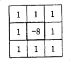
图2是示出上述实施方式1中、用于边缘提取处理的由3×3像素构成的注目区域的结构的图。FIG. 2 is a diagram showing the configuration of a region of interest composed of 3×3 pixels used in edge extraction processing in
图3是示出上述实施方式1中、能应用于3×3像素的注目区域上的各向同性边缘提取滤色器的结构的图。FIG. 3 is a diagram showing the configuration of an isotropic edge extraction color filter that can be applied to a 3×3 pixel region of interest in
图4是示出上述实施方式1中、能应用于3×3像素的注目区域上的水平边缘提取滤色器和垂直边缘提取滤色器的结构的图。4 is a diagram showing the configuration of a horizontal edge extraction color filter and a vertical edge extraction color filter that can be applied to a region of interest of 3×3 pixels in
图5是示出上述实施方式1中的无效边缘推定部的结构的框图。FIG. 5 is a block diagram showing the configuration of an invalid edge estimation unit in
图6是示出上述实施方式1中、噪声量相对信号电平的关系的曲线图。FIG. 6 is a graph showing the relationship between the amount of noise and the signal level in
图7是示出上述实施方式1中、无效边缘信号相对噪声量的关系的曲线图。FIG. 7 is a graph showing the relationship of the null edge signal with respect to the amount of noise in the first embodiment.
图8是示出上述实施方式1中的边缘模型的曲线图。FIG. 8 is a graph showing an edge model in
图9是用于说明上述实施方式1中、基于边缘模型的无效边缘信号的计算方法的曲线图。FIG. 9 is a graph for explaining a calculation method of a null edge signal based on an edge model in the first embodiment.
图10是示出上述实施方式1中的边缘修正部的结构的框图。FIG. 10 is a block diagram showing the configuration of an edge correcting unit in
图11是示出上述实施方式1中、边缘修正部中的核化处理的响应的曲线图。FIG. 11 is a graph showing the response of the coring process in the edge correction unit in the first embodiment.
图12是示出上述实施方式1中的无效边缘推定部的另一个结构例的框图。FIG. 12 is a block diagram showing another configuration example of the invalid edge estimation unit in the first embodiment.
图13是示出上述实施方式1中的图像处理系统的另一个结构例的框图。FIG. 13 is a block diagram showing another configuration example of the image processing system in
图14是示出上述实施方式1中、图像处理程序进行的信号处理整体的流程的流程图。FIG. 14 is a flowchart showing the overall flow of signal processing performed by the image processing program in the first embodiment.
图15是示出图14的步骤S4中的无效边缘推定处理的详细情况的流程图。FIG. 15 is a flowchart showing details of invalid edge estimation processing in step S4 of FIG. 14 .
图16是示出本发明的实施方式2中的图像处理系统的结构的框图。FIG. 16 is a block diagram showing the configuration of an image processing system in
图17是示出上述实施方式2中的噪声处理部的结构的框图。FIG. 17 is a block diagram showing the configuration of a noise processing unit in
图18是示出上述实施方式2中的无效边缘推定部的一个结构例的框图。FIG. 18 is a block diagram showing a configuration example of an invalid edge estimation unit in the second embodiment.
图19是示出上述实施方式2中的无效边缘推定部的另一个结构例的框图。FIG. 19 is a block diagram showing another configuration example of the invalid edge estimation unit in the second embodiment.
图20是示出上述实施方式2中的边缘修正部的结构的框图。FIG. 20 is a block diagram showing the configuration of an edge correction unit in
图21是示出上述实施方式2中、边缘修正部中的核化处理的响应的曲线图。FIG. 21 is a graph showing the response of the coring process in the edge correction unit in the second embodiment.
图22是示出上述实施方式2中、图像处理程序进行的信号处理整体的流程的流程图。FIG. 22 is a flowchart showing the overall flow of signal processing by the image processing program in the second embodiment.
图23是示出图22的步骤S30中的噪声处理的详细情况的流程图。FIG. 23 is a flowchart showing details of noise processing in step S30 of FIG. 22 .
图24是示出图22的步骤S31中的无效边缘推定处理的详细情况的流程图。FIG. 24 is a flowchart showing details of invalid edge estimation processing in step S31 of FIG. 22 .
图25是示出本发明的实施方式3中的图像处理系统的结构的框图。FIG. 25 is a block diagram showing the configuration of an image processing system in Embodiment 3 of the present invention.
图26是示出上述实施方式3中、拜尔(Bayer)型原色滤色器的结构的图。FIG. 26 is a diagram showing the configuration of a Bayer-type primary color filter in Embodiment 3. FIG.
图27是示出上述实施方式3中、色差线顺序型补色滤色器的结构的图。FIG. 27 is a diagram showing the configuration of a color difference line sequential color correction filter in Embodiment 3. FIG.
图28是示出上述实施方式3中的无效边缘推定部的一个结构例的框图。FIG. 28 is a block diagram showing a configuration example of an invalid edge estimation unit in the third embodiment.
图29是示出上述实施方式3中的无效边缘推定部的另一个结构例的框图。FIG. 29 is a block diagram showing another configuration example of the invalid edge estimation unit in the third embodiment.
图30是示出上述实施方式3中的边缘修正部的结构的框图。FIG. 30 is a block diagram showing the configuration of an edge correcting unit in Embodiment 3 described above.
图31是示出上述实施方式3中、核化处理中的响应的各实例的曲线图。FIG. 31 is a graph showing examples of responses in the coring process in Embodiment 3 described above.
图32是示出上述实施方式3中、图像处理程序进行的信号处理整体的流程的流程图。FIG. 32 is a flowchart showing the overall flow of signal processing performed by the image processing program in the third embodiment.
图33是示出图32的步骤S62中的无效边缘推定处理的详细情况的流程图。FIG. 33 is a flowchart showing details of invalid edge estimation processing in step S62 of FIG. 32 .
图34是示出本发明的实施方式4中的图像处理系统的结构的框图。FIG. 34 is a block diagram showing the configuration of an image processing system in Embodiment 4 of the present invention.
图35是示出上述实施方式4中、图像处理程序进行的信号处理整体的流程的流程图。FIG. 35 is a flowchart showing the overall flow of signal processing by the image processing program in the fourth embodiment.
图36是示出本发明的实施方式5中的图像处理系统的结构的框图。FIG. 36 is a block diagram showing the configuration of an image processing system in Embodiment 5 of the present invention.
图37是示出上述实施方式5中、对从前面配置有拜尔(Bayer)型原色滤色器的摄像元件得到的图像信号进行Y/C分离的方法的一例的图。FIG. 37 is a diagram showing an example of a method of performing Y/C separation on an image signal obtained from an image pickup element having a Bayer-type primary color filter disposed on the front in Embodiment 5. FIG.
图38是示出上述实施方式5中、与注目像素的颜色成分对应的水平边缘提取滤色器和垂直边缘提取滤色器的结构的图。38 is a diagram showing the configuration of a horizontal edge extraction color filter and a vertical edge extraction color filter corresponding to the color component of the pixel of interest in the fifth embodiment.
具体实施方式Detailed ways
以下,参照附图说明本发明的实施方式。Hereinafter, embodiments of the present invention will be described with reference to the drawings.
[实施方式1][Embodiment 1]
图1至图15示出本发明的实施方式1,图1是示出图像处理系统的结构的框图,图2是示出用于边缘提取处理的由3×3像素构成的注目区域的结构的图,图3是示出能应用于3×3像素的注目区域上的各向同性边缘提取滤色器的结构的图,图4是示出能应用于3×3像素的注目区域上的水平边缘提取滤色器和垂直边缘提取滤色器的结构的图,图5是示出无效边缘推定部的结构的框图,图6是示出噪声量相对信号电平的关系的曲线图,图7是示出无效边缘信号相对噪声量的关系的曲线图,图8是示出边缘模型的曲线图,图9是用于说明根据边缘模型的无效边缘信号的计算方法的曲线图,图10是示出边缘修正部的结构的框图,图11是示出边缘修正部中的核化处理的响应的曲线图,图12是示出无效边缘推定部的另一个结构例的框图,图13是示出图像处理系统的另一个结构例的框图,图14是示出图像处理程序进行的信号处理整体的流程的流程图,图15是示出图14的步骤S4中的无效边缘推定处理的详细情况的流程图。1 to 15
首先,参照图1对该图像处理系统的结构进行说明。图1所示的图像处理系统为在数字照相机上应用本发明的图像处理系统的实例。First, the configuration of the image processing system will be described with reference to FIG. 1 . The image processing system shown in FIG. 1 is an example of an image processing system applying the present invention to a digital camera.
该图像处理系统包括:透镜系统100、光圈101、CCD 102、温度传感器117、放大器103、A/D转换器104、缓冲器105、测光评价部106、对焦点检测部107、AF电机108、边缘提取部109、无效边缘推定部110、边缘修正部111、边缘强调部112、信号处理部113、输出部114、控制部115、以及外部I/F部116。The image processing system includes: a lens system 100, an
透镜系统100用于使被摄体的光学像在CCD 102的摄像面上成像。The lens system 100 is used to form the optical image of the object on the imaging surface of the CCD 102.
光圈101用于规定通过透镜系统100成像的被摄体光束的透射范围,从而改变在CCD 102的摄像面上成像的光学像的亮度。
CCD 102是用于对成像的光学像进行光电转换、并作为模拟图像信号而输出的摄像元件。另外,在本实施方式中,作为CCD 102,假设是黑白用单片CCD。并且,摄像元件也并不限定于CCD,当然也可以使用CMOS或其他的摄像元件。The CCD 102 is an imaging element for photoelectrically converting an imaged optical image and outputting it as an analog image signal. In addition, in this embodiment, as the CCD 102, it is assumed that it is a single-chip CCD for monochrome. Also, the imaging element is not limited to CCD, and of course CMOS or other imaging elements may be used.
温度传感器117是收集单元和噪声推定单元,其实际测量该CCD 102的温度并向控制部115输出。The temperature sensor 117 is a collecting unit and a noise estimating unit, which actually measures the temperature of the CCD 102 and outputs it to the
放大器103用于放大从CCD 102输出的图像信号。该放大器103的放大量是根据控制部115的控制而由测光评价部106来设定的。The
A/D转换器104用于根据控制部115的控制,将从CCD 102输出并通过放大器103放大后的模拟图像信号转换成数字图像信号。The A/
缓冲器105用于暂时存储从A/D转换器104输出的数字图像信号。The
在为预摄像模式时,测光评价部106根据控制部115的控制,求出存储在缓冲器105内的图像信号中的亮度电平,并考虑所设定的ISO灵敏度和抖动极限的快门速度等,对用于形成合适曝光的光圈101的光圈值、CCD 102的电子快门速度和放大器103的放大率等进行控制。In the pre-shooting mode, the
在为预摄像模式时,对焦点检测部107根据控制部115的控制,检测存储在缓冲器105内的图像信号中的边缘强度,并控制AF电机108使得该边缘强度为最大,从而得到对焦信号。In the pre-shooting mode, the focus
AF电机108是被对焦点检测部107控制,用于驱动透镜系统100所包含的AF透镜的驱动源。The
边缘提取部109是如下边缘提取单元:在为主摄像时,其根据控制部115的控制,从存储在缓冲器105内的图像信号中依次提取图2所示的3×3像素尺寸的注目区域,使用例如图3所示的边缘提取滤色器来提取注目像素中的边缘信号E。The
无效边缘推定部110是如下无效边缘推定单元:在为主摄像时,其根据控制部115的控制,从存储在缓冲器105内的图像信号中依次提取与边缘提取部109相同的3×3像素尺寸的注目区域,推定注目像素P11中的由噪声成分引起的无效边缘信号IE。The invalid
边缘修正部111是如下边缘修正单元:其根据控制部115的控制,使用来自无效边缘推定部110的无效边缘信号IE,对来自边缘提取部109的边缘信号E进行核化处理。The
边缘强调部112是如下边缘强调单元:其根据控制部115的控制,依次提取与边缘提取部109相同的3×3像素尺寸内的注目像素P11,使用来自边缘修正部111的完成了核化处理的边缘信号E’进行边缘强调处理。The
信号处理部113根据控制部115的控制,对从边缘强调部112输出的边缘强调后的图像信号进行公知的压缩处理等,并将处理后的信号向输出部114传送。The
输出部114将从信号处理部113输出的图像信号记录并保存到存储卡等记录介质中。The
控制部115由例如微型电子计算机等构成,是与放大器103、A/D转换器104、测光评价部106、对焦点检测部107、边缘提取部109、无效边缘推定部110、边缘修正部111、边缘强调部112、信号处理部113、输出部114、以及外部I/F部116双向连接,用于控制包括它们在内的该数字照相机整体的控制单元。另外,还向该控制部115输入来自配置在CCDThe
102附近的温度传感器117的信号。并且,该控制部115兼作收集单元、噪声推定单元和增益计算单元。102 near the signal of the temperature sensor 117. In addition, the
外部I/F部116是用于由用户向应用了图像处理系统的该数字照相机进行输入等的接口,其构成为包括:用于进行电源的接通/断开的电源开关、用于开始摄像操作的快门按钮、以及用于切换摄像模式或其他各种模式的模式切换按钮等。用户能够通过该外部I/F部116进行:利用两段式快门按钮的第1段按压而进行预摄像的开始输入;以及利用该快门按钮的第2段按压而进行主摄像的开始输入。另外,用户还能够通过该外部I/F部116进行ISO灵敏度的设定等。并且,该外部I/F部116将输入后的信息向控制部115输出。The external I/
接着,按照图像信号的流动来说明图1所示的数字照相机的作用。Next, the operation of the digital camera shown in FIG. 1 will be described in accordance with the flow of image signals.
用户在进行摄像前,通过外部I/F部116预先设定ISO灵敏度等摄像条件。The user sets imaging conditions such as ISO sensitivity in advance through the external I/
然后,用户半按压外部I/F部116的由两段式开关构成的开门按钮,该数字照相机进入预摄像模式。Then, the user half-presses the door open button constituted by the two-stage switch of the external I/
于是,通过透镜系统100和光圈101而成像的被摄体像由CCD 102进行光电转换,并作为模拟图像信号输出。Then, the subject image formed by the lens system 100 and the
该模拟图像信号通过放大器103进行考虑了ISO灵敏度的放大后,通过A/D转换器104转换成数字图像信号,并存储在缓冲器105内。The analog image signal is amplified in consideration of ISO sensitivity by the
存储在该缓冲器105内的图像信号分别向测光评价部106和对焦点检测部107传送。The image signals stored in the
测光评价部106根据图像信号,按照上述那样控制光圈101的光圈值、CCD 102的电子快门速度和放大器103的放大率等,以便形成合适曝光。The
对焦点检测部107根据图像信号,按照上述那样检测边缘强度,并控制AF电机108使得该边缘强度为最大,从而得到对焦信号。The focus
这样,在进行了焦点调节、曝光调节等后,当用户全按压外部I/F部116的由两段式开关构成的快门按钮时,该数字照相机进入主摄像模式。In this way, when the user fully presses the shutter button consisting of a two-stage switch of the external I/
于是,与预摄像同样,图像信号向缓冲器105传送。该主摄像根据通过测光评价部106求得的曝光条件、以及通过对焦点检测部107求得的对焦条件而进行,这些摄像时的条件向控制部115传送。Then, the image signal is transferred to the
通过主摄像得到的缓冲器105内的图像信号分别向边缘提取部109、无效边缘推定部110和边缘强调部112传送。The image signals in the
边缘提取部109根据控制部115的控制,依次提取图2所示的、包含注目像素P11的3×3像素尺寸的注目区域Pij(i=0~2,j=0~2),使用图3所示的边缘提取滤色器提取注目区域P11中的边缘信号E。该图3所示的边缘提取滤色器是各向同性的边缘提取滤色器的一例。另外,边缘提取滤色器并不限定于图3所示的各向同性的边缘提取滤色器。例如也可以构成为:分别单独地使用图4(A)所示的水平方向的边缘提取滤色器Eh和图4(B)所示的垂直方向的边缘提取滤色器Ev,如后所述,按照如下数学式1所示求取边缘信号E。According to the control of the
[数学式1][mathematical formula 1]
另外,不限定于这些边缘提取滤色器,当然也可以构成为使用其他公知的边缘提取法。并且,边缘提取部109将提取出的边缘信号E向边缘修正部111传送。In addition, it is not limited to these edge extraction color filters, and of course other known edge extraction methods may be used. Then, the
无效边缘推定部110根据控制部115的控制,依次提取与边缘提取部109相同的3×3像素尺寸的注目区域Pij,推定注目像素P11中的由噪声成分引起的无效边缘信号IE。并且,无效边缘推定部110将推定得到的由噪声成分引起的无效边缘信号IE向边缘修正部111传送。Under the control of the
边缘修正部111根据控制部115的控制,使用来自无效边缘推定部110的无效边缘信号IE,对来自边缘提取部109的边缘信号E进行核化处理。边缘修正部111将进行了核化处理的边缘信号E’向边缘强调部112传送。The
边缘强调部112根据控制部115的控制,依次提取与边缘提取部109相同的3×3像素尺寸内的注目像素P11,使用来自边缘修正部111的完成了核化处理的边缘信号E’,进行如下数学式2所示的边缘强调处理。The
[数学式2][mathematical formula 2]
P11’=P11+g·E’P 11 '=P 11 +g·E'
另外,该数学式2中的g表示规定的增益值,例如取0.5~4.0左右的值。并且,边缘强调部112将进行了边缘强调处理的图像信号向信号处理部113传送。In addition, g in this
在此,上述的边缘提取部109、无效边缘推定部110、边缘修正部111、边缘强调部112的各处理是根据控制部115的控制,以3×3像素尺寸的注目区域Pij为单位同步地进行。并且,为了对全部的图像信号进行处理(以全部的像素为注目像素进行处理),图2所示的3×3像素尺寸的注目区域相对邻接的注目区域各重复2行或2列地(即,以每隔1行或1列错开的方式)设定。Here, each process of the above-mentioned
信号处理部113根据控制部115的控制,对从边缘强调部112输出的边缘强调处理后的图像信号,按照上述那样进行公知的压缩处理等,并将处理后的信号向输出部114传送。The
输出部114将从信号处理部113输出的图像信号记录并保存到存储卡等记录介质中。The
接着,参照图5对无效边缘推定部110的结构的一例进行说明。Next, an example of the configuration of the invalid
该无效边缘推定部110包括:平均计算部200;是收集单元且是增益计算单元的增益计算部201;作为赋予单元的标准值赋予部202;作为记录单元的参数用ROM 203;作为参数选择单元的参数选择部204;作为插值单元的插值部205;以及作为插值单元的修正部206。This invalid
在此,缓冲器105连接到平均计算部200。并且,平均计算部200连接到参数选择部204。增益计算部201、标准值赋予部202和参数用ROM203分别连接到参数选择部204。参数选择部204分别连接到插值部205和修正部206。插值部205通过修正部206连接到边缘修正部111。Here, the
并且,控制部115与平均计算部200、增益计算部201、标准值赋予部202、参数选择部204、插值部205、以及修正部206双向连接,从而对它们进行控制。Furthermore, the
接着,对这样的无效边缘推定部110的作用进行说明。Next, the operation of such an invalid
平均计算部200根据控制部115的控制,从缓冲器105读取图2所示的注目区域Pij的图像信号,按照如下数学式3所示计算该注目区域Pij的图像信号的平均值AV。According to the control of the
[数学式3][mathematical formula 3]
并且,平均计算部200将计算出的平均值AV向参数选择部204传送。Then, the
并且,增益计算部201根据从控制部115传送的ISO灵敏度和关于曝光条件的信息中的至少一个来求取放大器103的放大量,并将求得的放大量向参数选择部204传送。Then, the
另一方面,控制部115从温度传感器117取得CCD 102的温度信息,并将取得的温度信息向参数选择部204传送。On the other hand, the
参数选择部204、插值部205、以及修正部206根据来自平均计算部200的注目区域的平均值、来自增益计算部201的增益的信息、和来自控制部115的温度信息,推定由噪声成分引起的无效边缘信号IE。The
在此,参照图6~图9对无效边缘信号IE的推定进行说明。Here, the estimation of the invalid edge signal IE will be described with reference to FIGS. 6 to 9 .
首先,图6绘出了信号电平L和噪声量N之间的关系的曲线。如图所示,噪声量N显示出随着信号电平L增加而增加的倾向,此时的增加相对信号电平L呈二次曲线性增加。因此,当按照日本特开2005-175718号公报所公开的那样,使用二次函数将该图6所示的增加的状态模型化时,则如以下数学式4所示。First, FIG. 6 plots a graph of the relationship between the signal level L and the noise amount N. As shown in FIG. As shown in the figure, the noise amount N tends to increase as the signal level L increases, and the increase at this time increases quadratically with respect to the signal level L. FIG. Therefore, when the state of increase shown in FIG. 6 is modeled using a quadratic function as disclosed in Japanese Patent Application Laid-Open No. 2005-175718, it becomes as shown in Mathematical Expression 4 below.
[数学式4][mathematical formula 4]
N=αL2+βL+γN=αL 2 +βL+γ
在此,α、β、γ是常数项。Here, α, β, and γ are constant terms.
但是,噪声量N不是只根据信号电平L的变化而变化,也根据摄像元件的温度或相对图像信号的增益而变化。例如,图6绘出了在某温度t下噪声量N相对关于增益的3种ISO灵敏度100(增益×1)、200(增益×2)、400(增益×4)的曲线。However, the amount of noise N changes not only with a change in the signal level L, but also with the temperature of the imaging element or the gain with respect to the image signal. For example, FIG. 6 plots the curves of the noise amount N against three kinds of ISO sensitivities 100 (gain×1), 200 (gain×2), and 400 (gain×4) with respect to gain at a certain temperature t.
图6所示的各条曲线形成数学式4所示的形状,但是其系数根据关于增益的ISO灵敏度而不同。并且,虽未图示,但噪声量N也根据摄像元件的温度而变化,通常显示出随着摄像元件的温度升高而增加的倾向(另外,图中是以20℃、50℃、80℃的温度为例)。The respective curves shown in FIG. 6 form the shape shown in Mathematical Formula 4, but their coefficients differ according to the ISO sensitivity with respect to the gain. In addition, although not shown in the figure, the noise amount N also changes according to the temperature of the imaging element, and generally shows a tendency to increase as the temperature of the imaging element increases (in addition, the figures are 20°C, 50°C, and 80°C temperature as an example).
这样,设增益为g、温度为t,以考虑了如上所述的噪声量N对增益g或温度t的依赖性的形式进行噪声模型的定式化时,则如以下数学式5所示。In this way, assuming that the gain is g and the temperature is t, and the noise model is formulated in such a manner that the above-mentioned dependence of the noise amount N on the gain g or temperature t is taken into consideration, it is expressed in the following Mathematical Expression 5.
[数学式5][mathematical formula 5]
N=αgtL2+βgtL+γgt N=α gt L 2 +β gt L+γ gt
在此,αgt、βgt、γgt是依赖于增益g和温度t而确定的常数项。Here, α gt , β gt , and γ gt are constant terms determined depending on the gain g and the temperature t.
接着,图7绘出了对平坦区域的图像信号施加噪声量N并对其应用图3或图4所示的边缘提取滤色器而得到的、由噪声成分引起的无效边缘信号IE的曲线。Next, FIG. 7 shows a graph of an invalid edge signal IE caused by a noise component obtained by applying a noise amount N to an image signal in a flat area and applying the edge extraction filter shown in FIG. 3 or 4 thereon.
如图所示,无效边缘信号IE显示出随着噪声量N增加而增加的倾向,此时的增加相对噪声量N呈三次曲线性增加。因此,当使用三次函数将该图7所示的增加的状态模型化时,则如以下数学式6所示。As shown in the figure, the invalid edge signal IE shows a tendency to increase with the increase of the noise amount N, and the increase at this time has a cubic curve with respect to the noise amount N. Therefore, when the state of increase shown in FIG. 7 is modeled using a cubic function, it becomes as shown in
[数学式6][mathematical formula 6]
IE=δN3+εN2+ζN+ηIE=δN 3 +εN 2 +ζN+η
在此,δ、ε、ζ、η是常数项,如果边缘提取滤色器固定,则可唯一确定。Here, δ, ε, ζ, and η are constant terms and can be uniquely determined if the edge extraction filter is fixed.
通过组合如上所述的数学式5和数学式6,能够使信号电平L和由噪声成分引起的无效边缘信号IE之间的关系形成为边缘模型而稳定化。By combining Mathematical Expression 5 and
但是,由于多次记录边缘模型的函数,每次都进行运算,使得计算无效边缘信号在处理上负荷大。为此,进行图8所示的边缘模型的简化。即,在图8所示的简化后的模型中,作为基准边缘模型而选择提供最大的无效边缘信号的函数,另外,用具有规定数量的拐点的折线近似该基准边缘模型。在此,折线的拐点通过由信号电平L和无效边缘信号IE构成的坐标数据(Ln,IEn)来表示。其中,n表示拐点的编号。并且,准备用于从上述基准边缘模型导出其他的边缘模型的修正系数kgt。该修正系数kgt使用各边缘模型和基准边缘模型通过最小二乘法来计算。通过使基准边缘模型乘以这样计算出的修正系数kgt,从而导出其他的边缘模型。However, since the function of the edge model is recorded multiple times and the calculation is performed each time, the calculation of the invalid edge signal requires a large processing load. For this purpose, a simplification of the edge model shown in FIG. 8 is performed. That is, in the simplified model shown in FIG. 8 , a function that provides the largest invalid edge signal is selected as the reference edge model, and the reference edge model is approximated by a broken line having a predetermined number of inflection points. Here, the inflection point of the broken line is represented by coordinate data (L n , IE n ) composed of the signal level L and the invalid edge signal IE. Among them, n represents the number of the inflection point. Furthermore, a correction coefficient k gt for deriving another edge model from the above reference edge model is prepared. The correction coefficient k gt is calculated by the least square method using each edge model and the reference edge model. Another edge model is derived by multiplying the reference edge model by the correction coefficient k gt calculated in this way.
参照图9说明从图8所示的简化后的边缘模型计算无效边缘信号的方法。A method of calculating an invalid edge signal from the simplified edge model shown in FIG. 8 will be described with reference to FIG. 9 .
例如,假设求取与给出的信号电平l、增益g、温度t对应的无效边缘信号IE。首先,检索信号电平l属于基准边缘模型的哪个区间。在此假设信号电平l属于(Ln,IEn)和(Ln+1,IEn+1)之间的区间。此时,利用如下数学式7所示的线性插值来求取基准边缘模型中的基准无效边缘信号IE1。For example, assume that an invalid edge signal IE corresponding to a given signal level l, gain g, and temperature t is obtained. First, it is searched which section of the reference edge model the signal level l belongs to. It is assumed here that the signal level l belongs to the interval between (L n , IE n ) and (L n+1 , IE n+1 ). At this time, the reference invalid edge signal IE 1 in the reference edge model is obtained by linear interpolation shown in Mathematical Expression 7 below.
[数学式7][mathematical formula 7]
接着,如以下数学式8所示,通过使求得的基准无效边缘信号IE1乘以修正系数kgt,从而求取无效边缘信号IE。Next, as shown in Mathematical Expression 8 below, the invalid edge signal IE is obtained by multiplying the obtained reference invalid edge signal IE 1 by the correction coefficient k gt .
[数学式8][mathematical formula 8]
IE=kgt·IE1 IE=k gt ·IE 1
返回按照图5的说明,如上所述的基准边缘模型的拐点的坐标数据(Ln、IEn)和修正系数kgt记录在参数用ROM 203中。Referring back to the description of FIG. 5 , the coordinate data (L n , IE n ) of the inflection point of the reference edge model and the correction coefficient k gt are recorded in the
参数选择部204分别根据来自平均计算部200的注目区域的平均值AV设定信号电平l,根据来自增益计算部201的增益的信息设定增益g,根据来自控制部115的温度信息设定温度t。The
接着,参数选择部204从参数用ROM 203中检索信号电平l所属区间的坐标数据(Ln,IEn)和(Ln+1,IEn+1),并将其向插值部205传送。并且,参数选择部204从参数用ROM 203中检索修正系数kgt,并将其向修正部206传送。Next, the
插值部205根据控制部115的控制,使用来自参数选择部204的信号电平l以及区间的坐标数据(Ln,IEn)和(Ln+1,IEn+1),根据数学式7计算基准边缘模型中的基准无效边缘信号IE1,并向修正部206传送。The
修正部206根据控制部115的控制,使用来自参数选择部204的修正系数kgt、和来自插值部205的基准无效边缘信号IE1,根据数学式8计算无效边缘信号IE,并将其作为注目像素P11的无效边缘信号IE。修正部206将推定出的无效边缘信号IE向边缘修正部111传送。The
另外,在如上所述的计算无效边缘信号的过程中,不必每次摄像时都求取温度t、增益g等信息。即,也可以构成为:预先在标准值赋予部202中记录任意的信息,省略计算过程。由此,能够实现处理的高速化和节电化等。In addition, in the process of calculating the invalid edge signal as described above, it is not necessary to obtain information such as temperature t and gain g every time an image is captured. That is, a configuration may be adopted in which arbitrary information is recorded in advance in the standard
接着,参照图10对边缘修正部111的结构的一例进行说明。Next, an example of the configuration of the
该边缘修正部111包括切换部300、作为核化单元的加法部301、作为核化单元的减法部302、以及作为核化单元的置换部303。The
边缘提取部109连接到切换部300。切换部300分别连接到加法部301、减法部302和置换部303。加法部301、减法部302和置换部303分别连接到边缘强调部112。并且,无效边缘推定部110分别连接到切换部300、加法部301和减法部302。The
控制部115与切换部300、加法部301、减法部302以及置换部303双向连接,从而对它们进行控制。The
接着,对这样的边缘修正部111的作用进行说明。Next, the operation of such an
切换部300根据控制部115的控制,分别从边缘提取部109读入相对注目像素P11的边缘信号E,从无效边缘推定部110读入相对注目像素P11的无效边缘信号IE。The switching unit 300 reads the edge signal E corresponding to the pixel of interest P11 from the
接着,切换部300在-IE>E的情况下,将边缘信号E向加法部301传送,在E>IE的情况下,将边缘信号E向减法部302传送,在IE≥E≥-IE的情况下,将边缘信号E向置换部303传送。Next, the switching unit 300 transmits the edge signal E to the addition unit 301 when -IE>E, and sends the edge signal E to the subtraction unit 302 when E>IE, and when IE≥E≥-IE In this case, the edge signal E is sent to the replacement unit 303 .
加法部301根据控制部115的控制,在从切换部300传送来边缘信号E的情况下,从无效边缘推定部110读入无效边缘信号IE,进行在边缘信号E中加上无效边缘信号IE的修正,并将修正后的边缘信号E’向边缘强调部112传送。The adding unit 301 reads the invalid edge signal IE from the invalid
并且,减法部302根据控制部115的控制,在从切换部300传送来边缘信号E的情况下,从无效边缘推定部110读入无效边缘信号IE,进行从边缘信号E中减去无效边缘信号IE的修正,并将修正后的边缘信号E’向边缘强调部112传送。Further, the subtraction unit 302 reads the invalid edge signal IE from the invalid
并且,置换部303根据控制部115的控制,在从切换部300传送来边缘信号E的情况下,进行将边缘信号E置换为0的修正,并将修正后的边缘信号E’向边缘强调部112传送。In addition, the replacement unit 303, under the control of the
上述三种处理通过如下数学式9来表示。The above-mentioned three kinds of processing are represented by the following
[数学式9][mathematical formula 9]
图11示出了该数学式9的特性,在输入边缘信号E的绝对值小于等于无效边缘信号IE的情况下,成为输出边缘信号E’为0的核化处理。Fig. 11 shows the characteristics of this
另外,在上述说明中,由噪声成分引起的边缘信号的推定使用了摄像元件的温度、ISO灵敏度、曝光信息等相关信息,但是不必限定于这样的结构。例如,如图12所示,也可以构成为:仅根据信号电平来推定由噪声成分引起的边缘信号。In addition, in the above description, the estimation of the edge signal due to the noise component uses relevant information such as the temperature of the imaging device, ISO sensitivity, exposure information, etc., but it is not necessarily limited to such a configuration. For example, as shown in FIG. 12 , a configuration may be adopted in which an edge signal due to a noise component is estimated from only the signal level.
图12形成为如下结构:从图5所示的结构中省略增益计算部201、标准值赋予部202和修正部206,通过注目像素提取部400和作为记录单元的参数用ROM 401来置换平均计算部200和参数用ROM 203。该图12所示的无效边缘推定部110中的其他基本结构与图5所示的相同,所以对相同的结构赋予相同的名称和符号,适当省略说明,主要仅对不同的部分进行说明。FIG. 12 has a structure in which the
缓冲器105连接到注目像素提取部400。注目像素提取部400连接到参数选择部204。参数用ROM 401连接到参数选择部204。参数选择部204连接到插值部205。插值部205连接到边缘修正部111。The
并且,控制部115也双向连接到注目像素提取部400,从而对其进行控制。In addition, the
注目像素提取部400根据控制部115的控制,从缓冲器105读入图2所示的注目像素P11,并向参数选择部204传送。The attention
参数选择部204和插值部205根据来自注目像素提取部400的注目像素P11的信号电平,推定由噪声成分引起的无效边缘信号IE。The
即,在参数用ROM 401中仅记录有图8所示的与规定温度和规定增益值相对应的单一边缘模型的拐点的坐标数据(Ln,IEn)。另外,以下将所记录的边缘模型作为基准边缘模型处理。That is, only the coordinate data (L n , IE n ) of the inflection point of the single edge model corresponding to a predetermined temperature and a predetermined gain value shown in FIG. 8 is recorded in the
参数选择部204从参数用ROM 401中检索注目像素P11的信号电平l所属区间的坐标数据(Ln,IEn)和(Ln+1,IEn+1),并将其向插值部205传送。The
插值部205根据控制部115的控制,使用来自参数选择部204的信号电平l以及区间的坐标数据(Ln,IEn)和(Ln+1,IEn+1),根据数学式7计算基准边缘模型中的基准无效边缘信号IE1。插值部205将计算出的基准无效边缘信号IE1作为无效边缘信号IE并传送给边缘修正部111。The
采用该图12所示的结构,能够简化推定由噪声成分引起的边缘信号所需的结构,所以能够实现图像处理系统的低成本化。According to the configuration shown in FIG. 12 , the configuration required for estimating the edge signal due to the noise component can be simplified, so that the cost of the image processing system can be reduced.
并且,在上述说明中,作为图像处理系统列举了数字照相机,所以如图1所示,图像处理系统一体地构成了包括透镜系统100、光圈101、CCD 102、温度传感器117、放大器103、A/D转换器104、测光评价部106、对焦点检测部107、AF电机108的摄像部。And, in above-mentioned description, enumerated digital camera as image processing system, so as shown in Figure 1, image processing system constitutes integrally and comprises lens system 100,
但是,作为图像处理系统不必限定于这样的结构。例如,如图13所示,摄像部也可以是独立体。即,图13所示的图像处理系统构成为:其通过独立的摄像部进行摄像,将以未处理的Raw数据格式记录在存储卡等记录介质中的图像信号从该记录介质中读出并处理。但是,此时图像信号所涉及的摄像条件等附带信息作为头部等记录在记录介质中。另外,从独立的摄像部向图像处理系统传送各种信息不限定于通过记录介质来进行,也可以通过通信线路等来进行。However, the image processing system is not necessarily limited to such a configuration. For example, as shown in FIG. 13, the imaging unit may be a separate body. That is, the image processing system shown in FIG. 13 is configured such that an image is captured by an independent imaging unit, and an image signal recorded in a recording medium such as a memory card in an unprocessed Raw data format is read out from the recording medium and processed. . However, at this time, incidental information such as imaging conditions related to the image signal is recorded on the recording medium as a header or the like. In addition, transmission of various information from an independent imaging unit to the image processing system is not limited to a recording medium, and may be performed through a communication line or the like.
图13所示的图像处理系统为如下结构:从图1所示的图像处理系统中省略透镜系统100、光圈101、CCD 102、温度传感器117、放大器103、A/D转换器104、测光评价部106、对焦点检测部107以及AF电机108,并追加了输入部500、头部信息解析部501。该图13所示的图像处理系统中的其他的基本结构与图1所示的相同,所以对相同的结构赋予相同的名称和符号,适当省略说明,主要仅对不同的部分进行说明。The image processing system shown in Figure 13 has the following structure: omit lens system 100,
输入部500分别连接到缓冲器105和头部信息解析部501。并且,控制部115还与输入部500以及头部信息解析部501双向连接,从而对它们进行控制。The
接着,该图13所示的图像处理系统中不同的作用如下所述。Next, different actions in the image processing system shown in FIG. 13 are as follows.
在通过例如鼠标或键盘等外部I/F部116开始进行处理操作后,保存在存储卡等记录介质中的图像信号和头部信息通过输入部500读入。Image signals and header information stored in a recording medium such as a memory card are read by the
从输入部500读入的信息中的图像信号传送给缓冲器105,头部信息传送给头部信息解析部501。The image signal among the information read from the
头部信息解析部501根据从输入部500传送来的头部信息,提取摄像时的信息(即,如上所述的曝光条件、ISO灵敏度、摄像元件的温度等)并传送给控制部115。Based on the header information sent from the
此后的处理与图1所示的图像处理系统相同。The subsequent processing is the same as that of the image processing system shown in FIG. 1 .
另外,在上述说明中,以利用硬件进行处理为前提,但是并不限定于这样的结构。例如,也可以将来自CCD 102的图像信号作为未处理状态的Raw数据记录在存储卡等记录介质中,并将摄像条件等附带信息(例如,来自控制部115的摄像时摄像元件的温度和增益等)作为头部信息预先记录在记录介质中。并且,使计算机执行其他的软件即图像处理程序,使计算机读取记录介质中的信息并处理。另外,从摄像部向计算机传送各种信息不限定于通过记录介质来进行,也可以通过通信线路等来进行。In addition, in the above description, it is assumed that processing is performed by hardware, but it is not limited to such a configuration. For example, the image signal from the CCD 102 may also be recorded in a recording medium such as a memory card as raw data in an unprocessed state, and additional information such as imaging conditions (for example, temperature and gain of the imaging element during imaging from the
参照图14对图像处理程序进行的处理的主程序进行说明。The main routine of the processing performed by the image processing program will be described with reference to FIG. 14 .
当开始进行该处理时,首先,读取图像信号,并读取摄像元件的温度和增益等头部信息(步骤S1)。When this process is started, first, an image signal is read, and header information such as temperature and gain of the imaging element is read (step S1 ).
接着,提取图2所示的、包含注目像素的3×3像素尺寸的注目区域(步骤S2)。Next, a region of interest having a size of 3×3 pixels including the pixel of interest shown in FIG. 2 is extracted (step S2 ).
并且,使用例如图3所示的各向同性的边缘提取滤色器,提取注目像素中的边缘信号(步骤S3)。Then, for example, an edge signal in a pixel of interest is extracted using an isotropic edge extraction filter as shown in FIG. 3 (step S3 ).
接着,如后面参照图15所作的说明那样,推定注目像素中的由噪声成分引起的无效边缘信号(步骤S4)。Next, as will be described later with reference to FIG. 15 , an invalid edge signal due to a noise component in the pixel of interest is estimated (step S4 ).
然后,判定边缘信号的绝对值是否小于等于无效边缘信号(步骤S5)。Then, it is determined whether the absolute value of the edge signal is smaller than or equal to the invalid edge signal (step S5).
在此,在边缘信号的绝对值大于无效边缘信号的情况下,再判定边缘信号是否大于无效边缘信号(步骤S6)。Here, if the absolute value of the edge signal is larger than the invalid edge signal, it is further determined whether the edge signal is larger than the invalid edge signal (step S6).
在该步骤S6中,在边缘信号小于等于无效边缘信号的情况下(-IE>E的情况下),在边缘信号中加上无效边缘信号(步骤S9)。In this step S6, when the edge signal is equal to or smaller than the invalid edge signal (in the case of -IE>E), the invalid edge signal is added to the edge signal (step S9).
并且,在步骤S6中,在边缘信号大于无效边缘信号的情况下(E>IE的情况下),从边缘信号中减去无效边缘信号(步骤S8)。And, in step S6, when the edge signal is larger than the invalid edge signal (in the case of E>IE), the invalid edge signal is subtracted from the edge signal (step S8).
另一方面,在步骤S5中,边缘信号的绝对值小于等于无效边缘信号的情况下(IE≥E≥-IE的情况下),将边缘信号置换为0(步骤S7)。On the other hand, in step S5, when the absolute value of the edge signal is equal to or less than the invalid edge signal (in the case of IE≥E≥-IE), the edge signal is replaced with 0 (step S7).
在步骤S7~S9中的任一步骤的处理结束后,使用按照数学式2所示修正后的边缘信号,对图像信号进行边缘强调处理(步骤S10)。After the processing in any one of steps S7 to S9 is completed, edge enhancement processing is performed on the image signal using the edge signal corrected as shown in Mathematical Expression 2 (step S10 ).
接着,判定是否对全部注目区域完成了处理(步骤S11),在未完成的情况下,返回上述步骤S2,对下一个注目区域重复进行如上所述的处理。Next, it is determined whether or not the processing has been completed for all the attention regions (step S11 ). If not, the process returns to the above-mentioned step S2 and the above-mentioned processing is repeated for the next attention region.
并且,在判定出对全部注目区域完成了处理的情况下,进行公知的压缩处理等信号处理(步骤S12),并输出处理后的图像信号(步骤S13),结束该一系列处理。Then, when it is determined that all the attention regions have been processed, signal processing such as known compression processing is performed (step S12), and the processed image signal is output (step S13), and the series of processing ends.
接着,参照图15,对上述图14的步骤S4中的无效边缘推定处理进行说明。Next, the invalid edge estimation process in step S4 of FIG. 14 described above will be described with reference to FIG. 15 .
当在图14的步骤S4中开始进行该处理时,首先,按照数学式3所示计算注目区域的平均值(步骤S20)。When this process is started in step S4 of FIG. 14 , first, the average value of the region of interest is calculated as shown in Mathematical Expression 3 (step S20 ).
接着,根据读入的头部信息来设定温度和增益等相关信息(步骤S21)。但是,在头部信息内不存在必需的参数的情况下,进行分配规定的标准值的处理。Next, relevant information such as temperature and gain is set based on the read header information (step S21). However, when the required parameter does not exist in the header information, a process of assigning a predetermined standard value is performed.
接着,读入基准边缘模型的坐标数据和修正系数(步骤S22)。Next, coordinate data and correction coefficients of the reference edge model are read (step S22).
并且,选择注目区域的平均值所属区间的坐标数据和对应的修正系数(步骤S23)。And, the coordinate data of the interval to which the average value of the attention area belongs and the corresponding correction coefficient are selected (step S23).
然后,通过数学式7所示的插值处理来求取基准无效边缘信号(步骤S24)。Then, a reference invalid edge signal is obtained by interpolation processing shown in Mathematical Expression 7 (step S24).
接着,通过数学式8所示的修正处理来求取无效边缘信号(步骤S25)。Next, an invalid edge signal is obtained by the correction process shown in Mathematical Expression 8 (step S25).
接着,输出计算出的无效边缘信号(步骤S26),从该处理返回图14所示的处理。Next, the calculated invalid edge signal is output (step S26 ), and the process returns to the process shown in FIG. 14 .
根据这样的实施方式1,能够构成如下图像处理系统:其在每次摄像时动态地求取由噪声成分引起的边缘信号所涉及的各种信息,对不能求取的信息设定标准值,根据这些信息、图像信号和基准边缘模型进行插值处理,从而求取由噪声成分引起的无效边缘信号,并根据求得的无效边缘信号对边缘信号进行修正处理。According to
这样的图像处理系统是通过性质相同的边缘信号来修正边缘信号,所以对混合有各种噪声的图像信号也能够稳定地进行高精度的边缘成分的提取。Such an image processing system corrects edge signals by using edge signals of the same nature, so it is possible to stably extract high-precision edge components from image signals mixed with various noises.
并且,因为每次摄像时动态地适应不同的条件,所以能够高精度地进行由噪声成分引起的边缘信号的推定。Furthermore, since different conditions are dynamically adapted for each imaging, edge signals due to noise components can be estimated with high precision.
另外,在不能得到必需的信息的情况下也设定标准值,所以能够推定由噪声成分引起的边缘信号,能够得到稳定的处理结果。Also, since the standard value is set even when necessary information cannot be obtained, edge signals due to noise components can be estimated and stable processing results can be obtained.
并且,因为计算由噪声成分引起的边缘信号是使用模型,所以能够高精度地进行边缘信号的推定。Furthermore, since the calculation of the edge signal due to the noise component uses the model, it is possible to estimate the edge signal with high accuracy.
此时,在采用简化后的模型时,基于简化后的模型的插值处理容易安装,所以能够构筑低成本的系统。In this case, when the simplified model is used, the interpolation processing based on the simplified model is easy to install, so a low-cost system can be constructed.
[实施方式2][Embodiment 2]
图16至图24示出本发明的实施方式2,图16是示出图像处理系统的结构的框图,图17是示出噪声处理部的结构的框图,图18是示出无效边缘推定部的一个结构例的框图,图19是示出无效边缘推定部的另一个结构例的框图,图20是示出边缘修正部的结构的框图,图21是示出边缘修正部中的核化处理的响应的曲线图,图22是示出图像处理程序进行的信号处理整体的流程的流程图,图23是示出图22的步骤S30中的噪声处理的详细情况的流程图,图24是示出图22的步骤S31中的无效边缘推定处理的详细情况的流程图。16 to 24
在该实施方式2中,对与上述实施方式1相同的部分赋予相同的符号并省略说明,主要仅对不同点进行说明。In this
首先,参照图16对该图像处理系统的结构进行说明。图16所示的图像处理系统为在数字照相机上应用本发明的图像处理系统的实例。First, the configuration of the image processing system will be described with reference to FIG. 16 . The image processing system shown in FIG. 16 is an example of an image processing system to which the present invention is applied to a digital camera.
该图16所示的图像处理系统对上述实施方式1的图1所示的图像处理系统作了部分变更。即,该图像处理系统构成为:将图1所示的无效边缘推定部110和边缘修正部111置换成作为无效边缘推定单元的无效边缘推定部601和作为边缘修正单元的边缘修正部602,还追加了作为噪声处理单元的噪声处理部600。其他的基本结构与实施方式1相同,对相同的结构赋予相同的名称和符号。The image processing system shown in FIG. 16 is partially modified from the image processing system shown in FIG. 1 in
以下主要仅对不同的部分进行说明。The following mainly only describes the different parts.
缓冲器105连接到测光评价部106、对焦点检测部107、噪声处理部600和边缘提取部109。噪声处理部600分别连接到边缘强调部112和无效边缘推定部601。边缘提取部109和无效边缘推定部601分别连接到边缘修正部602。边缘修正部602连接到边缘强调部112。The
并且,控制部115与噪声处理部600、无效边缘推定部601、边缘修正部602双向连接,从而对它们进行控制。Furthermore, the
接着,按照图像信号的流动对该图16所示的图像处理系统的作用进行说明。该实施方式2的图像处理系统的作用基本上与上述实施方式1相同,所以主要仅对不同的部分进行说明。Next, the operation of the image processing system shown in FIG. 16 will be described in accordance with the flow of image signals. The operation of the image processing system of this second embodiment is basically the same as that of the above-mentioned first embodiment, so only the different parts will be mainly described.
噪声处理部600根据控制部115的控制,依次提取图2所示的、包含注目像素P11的3×3像素尺寸的注目区域Pij。并且,按照日本特开2005-175718号公报所公开的那样,噪声处理部600根据噪声的模型来推定关于注目像素P11的噪声量N,进行平滑化处理。噪声处理部600分别将推定出的噪声量N向无效边缘推定部601传送,将进行了平滑化处理的注目像素NR_P11向边缘强调部112传送。Under the control of the
无效边缘推定部601根据控制部115的控制,从噪声处理部600读入相对注目像素P11的噪声量N,推定注目像素P11中的由噪声成分引起的无效边缘信号IE。无效边缘推定部601将推定出的由噪声成分引起的无效边缘信号IE向边缘修正部602传送。The invalid
边缘修正部602根据控制部115的控制,使用来自无效边缘推定部601的无效边缘信号IE和规定的函数,对来自边缘提取部109的边缘信号E进行变换处理。边缘修正部602将进行了变换处理的边缘信号E’向边缘强调部112传送。The
边缘强调部112根据控制部115的控制,使用来自边缘修正部602的变换处理边缘信号E’,对来自噪声处理部600的完成了平滑化处理的注目像素NR_P11进行如下数学式10所示的边缘强调处理。According to the control of the
[数学式10][mathematical formula 10]
P11’=NR_P11+g·E’P 11 '=NR_P 11 +g·E'
另外,该数学式10中的g表示规定的增益值,例如取0.5~4.0左右的值。并且,边缘强调部112将进行了边缘强调处理的图像信号向信号处理部113传送。In addition, g in this mathematical expression 10 represents a predetermined gain value, and takes a value of about 0.5 to 4.0, for example. Then, the
在此,上述的边缘提取部109、噪声处理部600、无效边缘推定部601、边缘修正部602以及边缘强调部112的各处理是根据控制部115的控制,以3×3像素尺寸的注目区域Pij为单位同步地进行。Here, each processing of the above-mentioned
信号处理部113根据控制部115的控制,对从边缘强调部112输出的边缘强调处理后的图像信号进行公知的压缩处理等,并将处理后的信号向输出部114传送。The
输出部114将从信号处理部113输出的图像信号记录并保存到存储卡等记录介质中。The
接着,参照图17对噪声处理部600的结构的一例进行说明。Next, an example of the configuration of the
该噪声处理部600包括:平均计算部700、作为噪声推定单元的增益计算部701、作为噪声推定单元的标准值赋予部702、作为噪声推定单元的噪声表部703、选择部704、作为降噪单元的第1平滑部705、以及作为降噪单元的第2平滑部706。The
缓冲器105分别连接到平均计算部700和选择部704。平均计算部700、增益计算部701和标准值赋予部702分别连接到噪声表部703。噪声表部703分别连接到选择部704、第1平滑部705、第2平滑部706和无效边缘推定部601。选择部704分别连接到第1平滑部705和第2平滑部706。第1平滑部705和第2平滑部706分别连接到边缘强调部112。The
控制部115与平均计算部700、增益计算部701、标准值赋予部702、噪声表部703、选择部704、第1平滑部705以及第2平滑部706双向连接,从而对它们进行控制。The
接着,对这种噪声处理部600的作用进行说明。Next, the operation of such a
平均计算部700根据控制部115的控制,从缓冲器105中依次提取图2所示的、包含注目像素P11的3×3像素尺寸的注目区域Pij,计算数学式3所示的平均值AV。平均计算部700将计算出的平均值AV向噪声表部703传送。According to the control of the
增益计算部701根据从控制部115传送来的ISO灵敏度和关于曝光条件的信息中的至少一个来求取放大器103的放大量,将求得的放大量向噪声表部703传送。The gain calculation unit 701 calculates an amplification amount of the
并且,控制部115从温度传感器117取得CCD 102的温度信息,将取得的温度信息向噪声表部703传送。Furthermore, the
噪声表部703根据来自平均计算部700的平均值、来自增益计算部701的增益的信息、以及来自控制部115的温度信息来推定噪声量。该噪声表部703是记录了温度、信号值电平、增益、噪声量之间的关系的检查表,通过例如日本特开2005-175718号公报所公开的方式构筑。噪声表部703将推定出的噪声量N和来自平均计算部700的平均值AV分别向选择部704、第1平滑部705和第2平滑部706传送。并且,噪声表部703将推定出的噪声量N也传送给无效边缘推定部601。The noise table unit 703 estimates the amount of noise based on the average value from the average calculation unit 700 , the gain information from the gain calculation unit 701 , and the temperature information from the
选择部704根据控制部115的控制,读入来自噪声表部703的平均值AV和噪声量N。然后,选择部704按照如下数学式11所示设定作为关于噪声量的容许范围的上限Noise_Up和下限Noise_Low。The selection unit 704 reads the average value AV and the noise amount N from the noise table unit 703 under the control of the
[数学式11][mathematical formula 11]
并且,选择部704根据控制部115的控制,从缓冲器105读入注目像素P11,判定是否属于上述容许范围。该判定分为以下三种:“属于噪声范围(Noise_Up≥P11≥Noise_Low)”、“高于噪声范围(P11>Noise_Up)”、以及“低于噪声范围(Noise_Low>P11)”。Then, the selection unit 704 reads the pixel of interest P 11 from the
选择部704在判定出“属于噪声范围”的情况下向第1平滑部705传送注目像素P11,除此以外的情况下向第2平滑部706传送注目像素P11。The selection unit 704 transmits the target pixel P 11 to the first smoothing unit 705 when it is determined that “belongs to the noise range”, and transmits the target pixel P 11 to the second smoothing unit 706 in other cases.
作为完成了平滑化处理的注目像素NR_P11,第1平滑部705按照如下数学式12所示,原样地使用来自噪声表部703的平均值AV并输出。As the smoothed target pixel NR_P 11 , the first smoothing unit 705 uses the average value AV from the noise table unit 703 as it is, as shown in Mathematical Expression 12 below, and outputs it.
[数学式12][mathematical formula 12]
NR_P11=AVNR_P 11 =AV
另一方面,作为完成了平滑化处理的注目像素NR_P11,第2平滑部706进行如下处理:即,使用来自噪声表部703的平均值AV和噪声量N,对来自选择部704的注目像素P11进行修正。首先,第2平滑部706在“高于噪声范围”的情况下按照如下数学式13所示进行修正。On the other hand, as the target pixel NR_P 11 that has been smoothed, the second smoothing unit 706 performs the following process: that is, the target pixel from the selection unit 704 P 11 is corrected. First, the second smoothing unit 706 performs correction as shown in Mathematical Expression 13 below in the case of "above the noise range".
[数学式13][mathematical formula 13]
并且,第2平滑部706在“低于噪声范围”的情况下按照如下数学式14所示进行修正。In addition, the second smoothing unit 706 performs correction as shown in Mathematical Expression 14 below in the case of "below the noise range".
[数学式14][mathematical formula 14]
这样,完成了第1平滑部705或第2平滑部706的平滑化处理的注目像素NR_P11向边缘强调部112传送。In this way, the pixel of interest NR_P 11 that has been smoothed by the first smoothing unit 705 or the second smoothing unit 706 is sent to the
接着,参照图18对无效边缘推定部601的结构的一例进行说明。Next, an example of the configuration of the invalid
该无效边缘推定部601包括:作为参数选择单元的参数选择部800、作为记录单元的参数用ROM 801、以及作为插值单元的插值部802。The invalid
噪声处理部600和参数用ROM 801分别连接到参数选择部800。参数选择部800连接到插值部802。插值部802连接到边缘修正部602。The
并且,控制部115与参数选择部800、插值部802双向连接,从而对它们进行控制。Furthermore, the
对这样的无效边缘推定部601的作用进行说明。The operation of such an invalid
参数选择部800和插值部802根据来自噪声处理部600的关于注目像素P11的噪声量N,推定由噪声成分引起的无效边缘信号IE。以下参照本发明的实施方式1的图7,对推定无效边缘信号IE的方法进行说明。The
如图7所示,无效边缘信号IE相对噪声量N的关系形成为使用了三次函数的边缘模型而被模型化。另外,用具有规定数量的拐点的折线近似该三次函数。在此,折线的拐点通过由噪声量N和无效边缘信号IE构成的坐标数据(Nn,IEn)来表示。其中,n表示拐点的编号。As shown in FIG. 7 , the relationship between the invalid edge signal IE and the noise amount N is modeled as an edge model using a cubic function. In addition, the cubic function is approximated by a polyline having a prescribed number of inflection points. Here, the inflection point of the broken line is represented by coordinate data (N n , IE n ) composed of the noise amount N and the invalid edge signal IE. Among them, n represents the number of the inflection point.
并且,为了求取与所给出的噪声量N对应的无效边缘信号IE,首先检索噪声量N属于边缘模型的哪个区间。在此,假设噪声量N属于(Nn,IEn)和(Nn+1,IEn+1)之间的区间。此时,通过如下数学式15所示的线性插值来求取边缘模型中的无效边缘信号IE。Then, in order to obtain the invalid edge signal IE corresponding to the given noise amount N, it is first searched which section of the edge model the noise amount N belongs to. Here, it is assumed that the noise amount N belongs to a section between (N n , IE n ) and (N n+1 , IE n+1 ). At this time, the invalid edge signal IE in the edge model is obtained by linear interpolation shown in Mathematical Expression 15 below.
[数学式15][mathematical formula 15]
返回按照图18的说明,如上所述的边缘模型的拐点的坐标数据(Nn,IEn)记录在参数用ROM 801中。Referring back to the description of FIG. 18 , the coordinate data (N n , IE n ) of the inflection point of the edge model as described above is recorded in the
参数选择部800根据控制部115的控制,读入来自噪声处理部600的关于注目像素P11的噪声量N。接着,参数选择部800从参数用ROM 801中检索噪声量N所属区间的坐标数据(Nn,IEn)和(Nn+1,IEn+1),并将其向插值部802传送。The
插值部802根据控制部115的控制,使用来自参数选择部800的噪声量N以及区间的坐标数据(Nn,IEn)和(Nn+1,IEn+1),根据数学式15计算无效边缘信号IE,并将计算出的无效边缘信号IE向边缘修正部602传送。另外,在上述说明中是通过基于模型的插值运算来推定由噪声成分引起的边缘信号,但是不必限定于这样的结构。例如,如图19所示,也可以构成为使用表来推定由噪声成分引起的边缘信号。The
在此,参照图19对无效边缘推定部601的结构的另一个实例进行说明。Here, another example of the configuration of the invalid
该无效边缘推定部601包括作为记录单元的无效边缘表部803。The invalid
噪声处理部600连接到无效边缘表部803。无效边缘表部803连接到边缘修正部602。The
并且,控制部115与无效边缘表部803双向连接,从而对其进行控制。Furthermore, the
在此,无效边缘表部803是记录了图7所示的、无效边缘信号IE相对噪声量N的关系的表。Here, the invalid
无效边缘表部803根据控制部115的控制,从噪声处理部600读入相对注目像素P11的噪声量N,将对应的无效边缘信号IE向边缘修正部602传送。The invalid
参照图20,对边缘修正部602的结构的一例进行说明。An example of the configuration of the
该边缘修正部602包括切换部900、作为常数计算单元的常数计算部901、以及作为函数变换单元的变换部902。The
边缘提取部109连接到切换部900。切换部900分别连接到变换部902和边缘强调部112。变换部902连接到边缘强调部112。无效边缘推定部601分别连接到切换部900和常数计算部901。常数计算部901连接到变换部902。The
并且,控制部115与切换部900、常数计算部901、变换部902双向连接,从而对它们进行控制。Furthermore, the
接着,对这样的边缘修正部602的作用进行说明。Next, the operation of such an
常数计算部901根据控制部115的控制,从无效边缘推定部601读入相对注目像素P11的无效边缘信号IE。并且,常数计算部901计算图21所示的具有响应特性的函数的常数项。在此,图21示出输入边缘信号E、输出变换后的边缘信号E’的函数的形状,该函数组合2个一次函数和1个三次函数而构成。The
[数学式16][mathematical formula 16]
常数计算部901仅计算数学式16所示的函数的常数项、实质上为三次函数的三次项的系数即2/(3·IE2)这一项,并向变换部902传送。The
切换部900根据控制部115的控制,分别从边缘提取部109读入相对注目像素P11的边缘信号E,从无效边缘推定部601读入相对注目像素P11的无效边缘信号IE。并且,切换部900比较边缘信号E和无效边缘信号IE,在IE≥E≥-IE的情况下向变换部902传送边缘信号E,在除此以外的情况下向边缘强调部112传送边缘信号E。The
变换部902根据控制部115的控制,在从切换部900传送来边缘信号E的情况下,使用来自常数计算部901的常数项,通过数学式16中的三次函数变换边缘信号E,将变换后的边缘信号E’向边缘强调部112传送。According to the control of the
另外,在上述说明中列举了摄像部被一体化的图像处理系统,但是并不限定于这样的结构,与上述实施方式1同样,也可以是与摄像部分离的结构的图像处理系统。In addition, in the above description, the image processing system in which the imaging unit is integrated was exemplified. However, it is not limited to such a configuration. Like the first embodiment, an image processing system having a configuration separate from the imaging unit may be used.
并且,在上述说明中,以利用硬件进行处理为前提,但是并不限定于这样的结构,例如,也可以将来自CCD 102的图像信号作为未处理状态的Raw数据记录在存储卡等记录介质中,并且将摄像条件等附带信息(例如,来自控制部115的摄像时摄像元件的温度和增益等)作为头部信息预先记录在记录介质中。并且,使计算机执行其他的软件即图像处理程序,使计算机读取存储介质中的信息并处理。另外,从摄像部向计算机传送各种信息并限定于通过记录介质来进行,也可以通过通信线路等来进行。In addition, in the above description, it is assumed that the processing is performed by hardware, but it is not limited to such a structure. For example, the image signal from the CCD 102 may be recorded in a recording medium such as a memory card as raw data in an unprocessed state. , and additional information such as imaging conditions (for example, the temperature and gain of the imaging element during imaging from the control unit 115) is pre-recorded in the recording medium as header information. In addition, the computer is made to execute an image processing program which is other software, and the computer is made to read and process information in the storage medium. In addition, the transmission of various information from the imaging unit to the computer is not limited to a recording medium, but may be performed through a communication line or the like.
参照图22对图像处理程序进行的处理的主程序进行说明。另外,对该图22所示的处理中的、与上述实施方式1的图14所示的处理大致相同的处理赋予相同符号。The main routine of the processing performed by the image processing program will be described with reference to FIG. 22 . In addition, among the processing shown in FIG. 22 , the processing substantially the same as the processing shown in FIG. 14 of the first embodiment described above is given the same reference numeral.
当开始进行该处理时,首先,读入图像信号,并且读入摄像元件的温度、增益等头部信息(步骤S1)。When this process is started, first, an image signal is read, and header information such as temperature and gain of the imaging element is read (step S1).
接着,提取图2所示的、包含注目像素的3×3像素尺寸的注目区域(步骤S2)。Next, a region of interest having a size of 3×3 pixels including the pixel of interest shown in FIG. 2 is extracted (step S2 ).
并且,例如使用图3所示的各向同性的边缘提取滤色器提取注目像素中的边缘信号(步骤S3)。Then, for example, an edge signal in a pixel of interest is extracted using an isotropic edge extraction filter shown in FIG. 3 (step S3 ).
另一方面,如后面参照图23所作的说明那样,对注目像素进行噪声处理(步骤S30)。On the other hand, as described later with reference to FIG. 23 , noise processing is performed on the pixel of interest (step S30 ).
在步骤S3的处理和步骤S30的处理结束后,如后面参照图24所作的说明那样,推定注目像素中的由噪声成分引起的无效边缘信号(步骤S31)。After the processing in step S3 and the processing in step S30 are completed, as described later with reference to FIG. 24 , an invalid edge signal due to a noise component in the pixel of interest is estimated (step S31 ).
接着,判定边缘信号的绝对值是否小于等于无效边缘信号(步骤S5)。Next, it is determined whether the absolute value of the edge signal is smaller than or equal to the invalid edge signal (step S5).
在此,在边缘信号小于等于无效边缘信号的情况下,使用数学式16所示的三次函数来变换边缘信号(步骤S32)。Here, when the edge signal is equal to or smaller than the invalid edge signal, the edge signal is converted using the cubic function shown in Mathematical Expression 16 (step S32).
在步骤S30的处理结束后,在进行该步骤S32的处理的情况下,使用变换后的边缘信号,对完成了噪声处理的图像信号按照数学式10所示进行边缘强调处理。并且,在步骤S30的处理结束后,在步骤S5中判定出边缘信号的绝对值大于无效边缘信号的情况下,将此时的边缘信号作为变换后的边缘信号使用,对完成了噪声处理的图像信号按照数学式10所示进行边缘强调处理(步骤S10)。After the processing of step S30 is completed, when the processing of step S32 is performed, edge enhancement processing is performed on the noise-processed image signal as shown in Mathematical Expression 10 using the transformed edge signal. And, after the processing of step S30 ends, when it is determined in step S5 that the absolute value of the edge signal is greater than the invalid edge signal, the edge signal at this time is used as an edge signal after conversion, and the noise-processed image The signal is subjected to edge emphasis processing as shown in Mathematical Formula 10 (step S10).
接着,判定是否对全部注目区域完成了处理(步骤S11),在未完成的情况下,返回上述步骤S2,对下一个注目区域反复进行如上所述的处理。Next, it is determined whether or not the processing has been completed for all the attention regions (step S11 ). If not, the process returns to the above-mentioned step S2 and the above-mentioned processing is repeated for the next attention region.
并且,在判定出对全部注目区域完成了处理的情况下,进行公知的压缩处理等信号处理(步骤S12),输出处理后的图像信号(步骤S13),结束该一系列处理。Then, when it is judged that the processing has been completed for all the regions of interest, signal processing such as known compression processing is performed (step S12 ), the processed image signal is output (step S13 ), and the series of processing ends.
接着,参照图23,对上述图22的步骤S30中的噪声处理进行说明。Next, the noise processing in step S30 of FIG. 22 described above will be described with reference to FIG. 23 .
当在图22的步骤S30中开始进行该处理时,首先根据所读入的头部信息来设定温度和增益等相关信息(步骤S40)。但是,在头部信息内不存在必需的参数的情况下,进行分配规定的标准值的处理。When this process is started in step S30 of FIG. 22 , relevant information such as temperature and gain is first set based on the read header information (step S40 ). However, when the required parameter does not exist in the header information, a process of assigning a predetermined standard value is performed.
接着,读入噪声表(步骤S41),使用所读入的噪声表,求取相对注目像素的噪声量(步骤S42)。Next, the noise table is read (step S41), and the amount of noise relative to the pixel of interest is obtained using the read noise table (step S42).
并且,根据数学式11所示的容许范围,判定噪声量是否属于容许范围内(步骤S43)。Then, based on the allowable range shown in Mathematical Expression 11, it is determined whether or not the amount of noise is within the allowable range (step S43).
在此,在判定出噪声量属于容许范围内的情况下,进行数学式12所示的平滑化处理(步骤S44)。Here, when it is determined that the amount of noise is within the allowable range, the smoothing process shown in Mathematical Expression 12 is performed (step S44 ).
并且,在判定出噪声量不属于容许范围内的情况下,进行数学式13或数学式14所示的平滑化处理(步骤S45)。Then, when it is determined that the amount of noise is not within the allowable range, smoothing processing shown in Mathematical Expression 13 or Mathematical Expression 14 is performed (step S45 ).
在步骤S44或步骤S45的处理结束后,将完成了噪声处理的图像信号输出(步骤S46),从该处理返回图22所示的处理。After the processing in step S44 or step S45 ends, the noise-processed image signal is output (step S46 ), and the processing returns to the processing shown in FIG. 22 .
接着,参照图24对上述图22的步骤S31中的无效边缘推定处理进行说明。Next, the invalid edge estimation process in step S31 of FIG. 22 described above will be described with reference to FIG. 24 .
当开始进行该处理时,首先,读入注目像素的噪声量(步骤S50),并且读入边缘模型的坐标数据(步骤S51)。When this process is started, first, the noise amount of the pixel of interest is read (step S50), and the coordinate data of the edge model is read (step S51).
接着,选择注目区域的噪声量所属区间的坐标数据(步骤S52)。Next, the coordinate data of the section to which the noise amount of the attention area belongs is selected (step S52).
接着,通过数学式15所示的插值处理来求取基准无效边缘信号(步骤S53)。Next, a reference invalid edge signal is obtained by interpolation processing shown in Mathematical Expression 15 (step S53).
然后,输出计算出的无效边缘信号(步骤S54),从该处理返回图22所示的处理。Then, the calculated invalid edge signal is output (step S54), and the process returns to the process shown in FIG. 22 from this process.
根据这样的实施方式2,可以构成如下图像处理系统:其通过推定噪声成分来进行降噪处理,根据所推定的噪声成分,动态地推定由噪声成分引起的边缘信号,根据由噪声成分引起的边缘信号对来自原信号的边缘信号进行修正处理。According to the second embodiment, it is possible to configure an image processing system that performs noise reduction processing by estimating noise components, dynamically estimates edge signals caused by noise components based on the estimated noise components, and The signal corrects the edge signal from the original signal.
这样的图像处理系统是通过性质相同的边缘信号来修正边缘信号,所以对混合有多种噪声的图像信号也能够稳定地进行高精度的边缘成分的提取。Such an image processing system corrects edge signals by using edge signals of the same nature, so it is possible to stably extract high-precision edge components from image signals mixed with various types of noise.
并且,在通过降噪处理来抑制噪声影响的同时,能够得到保存了微小信号的高品位的边缘成分。Furthermore, while suppressing the influence of noise by noise reduction processing, it is possible to obtain high-quality edge components that preserve minute signals.
另外,因为组合使用了降噪处理和边缘信号的修正处理,所以能够缩小系统的规模,能够实现低成本化。In addition, since the noise reduction processing and the edge signal correction processing are used in combination, the scale of the system can be reduced and the cost can be reduced.
并且,因为计算由噪声成分引起的边缘信号是使用模型,所以能够在实现低成本的同时进行高精度的边缘信号的推定。In addition, since the calculation of the edge signal due to the noise component uses the model, it is possible to estimate the edge signal with high precision while achieving low cost.
另一方面,在使用表计算由噪声成分引起的边缘信号的情况下,能够高速地进行高精度的边缘信号的推定。On the other hand, when calculating an edge signal due to a noise component using a table, it is possible to estimate an edge signal with high speed and high accuracy.
并且,因为使用将多个函数组合而得到的连续的单调递增函数来进行边缘信号的变换,所以能够确保边缘信号的连续性,能够得到高品位的边缘信号。Furthermore, since the edge signal is converted using a continuous monotonically increasing function obtained by combining a plurality of functions, the continuity of the edge signal can be ensured, and a high-quality edge signal can be obtained.
[实施方式3][Embodiment 3]
图25至图33示出本发明的实施方式3,图25是示出图像处理系统的结构的框图,图26是示出拜尔(Bayer)型原色滤色器的结构的图,图27是示出色差线顺序型补色滤色器的结构的图,图28是示出无效边缘推定部的一个结构例的框图,图29是示出无效边缘推定部的另一个结构例的框图,图30是示出边缘修正部的结构的框图,图31是示出核化处理中的响应的各实例的曲线图,图32是示出图像处理程序进行的信号处理整体的流程的流程图,图33是示出图32的步骤S62中的无效边缘推定处理的详细情况的流程图。25 to 33 show Embodiment 3 of the present invention, FIG. 25 is a block diagram showing the configuration of an image processing system, FIG. 26 is a diagram showing a configuration of a Bayer-type primary color filter, and FIG. 27 is 28 is a block diagram showing a configuration example of an invalid edge estimating unit, FIG. 29 is a block diagram showing another configuration example of an invalid edge estimating unit, and FIG. 30 is a block diagram showing the configuration of an edge correction unit, FIG. 31 is a graph showing examples of responses in coring processing, FIG. 32 is a flowchart showing the overall flow of signal processing by an image processing program, and FIG. 33 It is a flowchart showing the details of the invalid edge estimation process in step S62 of FIG. 32 .
在该实施方式3中,对与上述实施方式1、2相同的部分赋予相同的符号并省略说明,主要仅对不同点进行说明。In this Embodiment 3, the same code|symbol is attached|subjected to the same part as the said
首先,参照图25对该图像处理系统的结构进行说明。图25所示的图像处理系统为在数字照相机上应用本发明的图像处理系统的实例。First, the configuration of the image processing system will be described with reference to FIG. 25 . The image processing system shown in FIG. 25 is an example of an image processing system to which the present invention is applied to a digital camera.
该图25所示的图像处理系统对上述实施方式1的图1所示的图像处理系统作了部分变更。即,该图像处理系统构成为:将图1所示的CCD102、无效边缘推定部110和边缘修正部111置换成彩色CCD 1000、作为无效边缘推定单元的无效边缘推定部1005和作为边缘修正单元的边缘修正部1006,还追加了预设白平衡部1001、插值部1002、作为Y/C分离单元的Y/C分离部1003、缓冲器1004和Y/C合成部1007。其他的基本结构与实施方式1相同,对相同的结构赋予相同的名称和符号。The image processing system shown in FIG. 25 is partially modified from the image processing system shown in FIG. 1 in
以下主要仅对不同的部分进行说明。The following mainly only describes the different parts.
通过透镜系统100、光圈101、彩色CCD 1000拍摄到的图像信号向放大器103传送。The image signal captured by the lens system 100,
缓冲器105分别连接到预设白平衡部1001、插值部1002、测光评价部106和对焦点检测部107。预设白平衡部1001连接到放大器103。插值部1002连接到Y/C分离部1003。Y/C分离部1003连接到缓冲器1004。缓冲器1004分别连接到边缘提取部109、边缘强调部112和无效边缘推定部1005。边缘提取部109和无效边缘推定部1005分别连接到边缘修正部1006。边缘修正部1006连接到边缘强调部112。边缘强调部112连接到Y/C合成部1007。Y/C合成部1007连接到信号处理部113。The
并且,来自配置在彩色CCD 1000附近的温度传感器117的信号连接到控制部115。And, the signal from the temperature sensor 117 arranged near the color CCD 1000 is connected to the
并且,控制部115与预设白平衡部1001、插值部1002、Y/C分离部1003、无效边缘推定部1005、边缘修正部1006、以及Y/C合成部1007双向连接,从而对它们进行控制。And, the
接着,沿着图像信号的流动对该图25所示的图像处理系统的作用进行说明。该实施方式3的图像处理系统的作用基本上与上述实施方式1相同,所以主要仅对不同的部分进行说明。Next, the operation of the image processing system shown in FIG. 25 will be described along the flow of the image signal. The operation of the image processing system of the third embodiment is basically the same as that of the first embodiment, so only the different parts will be mainly described.
用户半按压外部I/F部116的由两段式开关构成的快门按钮后,该数字照相机进入预摄像模式。When the user half-presses the shutter button consisting of a two-stage switch of the external I/
于是,通过透镜系统100和光圈101而成像的被摄体像由彩色CCD1000进行光电转换,并作为模拟图像信号输出。Then, the subject image formed by the lens system 100 and the
该模拟图像信号通过放大器103进行考虑了ISO灵敏度或白平衡的放大后,通过A/D转换器104转换成数字图像信号,并存储在缓冲器105内。The analog image signal is amplified by the
另外,在本实施方式中,作为彩色CCD 1000,假设是在前面配置有图26所示的拜尔(Bayer)型原色滤色器的单片摄像元件。并且,与上述实施方式1同样,摄像元件并不限定于CCD,也可以使用CMOS或其他的摄像元件。In addition, in this embodiment, as the color CCD 1000, it is assumed that a single-chip imaging element having a Bayer type primary color filter shown in FIG. 26 is arranged on the front. Furthermore, as in the first embodiment described above, the imaging element is not limited to a CCD, and a CMOS or other imaging element may be used.
在此,参照图26对拜尔(Bayer)型原色滤色器的结构进行说明。Here, the structure of a Bayer type primary color filter will be described with reference to FIG. 26 .
图26所示的拜尔(Bayer)型原色滤色器以2×2像素为基本单位,在该基本单位内的对角的像素位置上配置各一个红色(R)、蓝色(B)滤色器,在剩余的对角的像素位置上配置绿色(G)滤色器。The Bayer (Bayer) type primary color filter shown in Figure 26 takes 2×2 pixels as the basic unit, and a red (R) and a blue (B) filter are respectively arranged at the diagonal pixel positions in the basic unit. color filters, and green (G) color filters are arranged on the remaining diagonal pixel positions.
接着,缓冲器105内的图像信号分别向测光评价部106、对焦点检测部107、预设白平衡部1001传送。Next, the image signals in the
其中的预设白平衡部1001按照每个颜色信号累加(即,累计地进行加法运算)存储在缓冲器105内的图像信号中的规定电平范围内的信号,从而计算简化白平衡系数。预设白平衡部1001将计算出的系数向放大器103传送,通过对每个颜色信号乘以不同的增益,从而使其进行白平衡。Among them, the preset white balance unit 1001 accumulates (that is, cumulatively adds) signals within a predetermined level range among the image signals stored in the
这样,在进行了焦点调节、曝光调节和简化白平衡调节等后,当用户全按压外部I/F部116的由两段式开关构成的快门按钮时,该数字照相机进入主摄像模式。In this way, after performing focus adjustment, exposure adjustment, and simplified white balance adjustment, etc., when the user fully presses the shutter button consisting of a two-stage switch of the external I/
于是,与预摄像同样,图像信号向缓冲器105传送。该主摄像根据通过预设白平衡部1001求得的简化白平衡系数、通过测光评价部106求得的曝光条件、以及通过对焦点检测部107求得的对焦条件而进行,且这些摄像时的条件向控制部115传送。Then, the image signal is transferred to the
通过主摄像得到的缓冲器105内的图像信号首先向插值部1002传送。The image signal in the
该插值部1002根据控制部115的控制,通过公知的插值处理来生成由R、G、B三片构成的图像信号,并向Y/C分离部1003传送。The interpolation unit 1002 generates an image signal composed of three slices of R, G, and B through known interpolation processing under the control of the
Y/C分离部1003根据控制部115的控制,按照如下数学式17所示将R、G、B信号分离为亮度信号Y和色差信号Cb、Cr。The Y/C separation unit 1003 separates the R, G, and B signals into a luminance signal Y and color difference signals Cb and Cr as shown in the following Mathematical Expression 17 under the control of the
[数学式17][mathematical formula 17]
Y=0.29900R+0.58700G+0.11400BY=0.29900R+0.58700G+0.11400B
Cb=-0.16874R-0.33126G+0.50000BCb=-0.16874R-0.33126G+0.50000B
Cr=0.50000R-0.41869G-0.08131BCr=0.50000R-0.41869G-0.08131B
通过Y/C分离部1003计算出的亮度信号和色差信号向缓冲器1004传送并保存。The luminance signal and color difference signal calculated by the Y/C separation unit 1003 are transferred to and stored in the
边缘提取部109根据控制部115的控制,从缓冲器1004内的亮度信号Y中依次提取图2所示的、包含注目像素P11的3×3像素尺寸的注目区域Pij,并使用图3所示的边缘提取滤色器来提取注目像素P11中的边缘信号E。边缘提取部109将提取出的边缘信号E向边缘修正部1006传送。According to the control of the
无效边缘推定部1005根据控制部115的控制,从缓冲器1004内的亮度信号Y中依次提取与所述边缘提取部109相同的3×3像素尺寸的注目区域Pij,推定注目像素P11中的由噪声成分引起的无效边缘信号IE。无效边缘推定部1005将推定出的由噪声成分引起的无效边缘信号IE向边缘修正部1006传送。According to the control of the
边缘修正部1006根据控制部115的控制,使用来自无效边缘推定部1005的无效边缘信号IE,对来自边缘提取部109的边缘信号E进行核化处理。边缘修正部1006将进行了核化处理的边缘信号E’向边缘强调部112传送。The
边缘强调部112根据控制部115的控制,从缓冲器1004内的亮度信号Y中依次提取与边缘提取部109相同的、对应于注目像素P11的亮度信号Y,使用来自边缘修正部111的完成了核化处理的边缘信号E’进行如下数学式18所示的边缘强调处理。According to the control of the
[数学式18][mathematical formula 18]
Y’=Y+g·E’Y'=Y+g · E'
另外,该数学式18中的g表示规定的增益值,例如取0.5~4.0左右的值。In addition, g in this mathematical expression 18 represents a predetermined gain value, and takes a value of about 0.5 to 4.0, for example.
并且,边缘强调部112从缓冲器1004内的色差信号Cb、Cr中提取与边缘提取部109相同的、与注目像素P11对应的色差信号Cb、Cr。并且,边缘强调部112将提取出的色差信号Cb、Cr和边缘强调处理后的亮度信号Y’向Y/C合成部1007传送。Then, the
Y/C合成部1007根据控制部115的控制,按照如下数学式19所示,由边缘强调处理后的亮度信号Y’和色差信号Cb、Cr合成RGB三种信号(R’、G’、B’)。According to the control of the
[数学式19][mathematical formula 19]
R’=Y’+1.40200CrR'=Y'+1.40200Cr
G’=Y’-0.34414Cb-0.71414CrG'=Y'-0.34414Cb-0.71414Cr
B’=Y’+1.77200CbB'=Y'+1.77200Cb
Y/C合成部1007将合成后的R’、G’、B’信号向信号处理部113传送。The Y/C synthesis unit 1007 sends the synthesized R', G', and B' signals to the
另外,如上所述的边缘提取部109、无效边缘推定部1005、边缘修正部1006、边缘强调部112、Y/C合成部1007的各处理是根据控制部115的控制,以3×3像素尺寸的注目区域Pij为单位同步地进行的。In addition, each processing of the above-mentioned
信号处理部113根据控制部115的控制,对从边缘强调部112输出的边缘强调处理后的图像信号进行公知的色度强调处理和压缩处理等,并将处理后的信号向输出部114传送。The
输出部114将从信号处理部113输出的图像信号记录并保存到存储卡等记录介质中。The
接着,参照图28对无效边缘推定部1005的结构的一例进行说明。Next, an example of the configuration of the invalid
该无效边缘推定部1005与上述实施方式1的图5所示的无效边缘推定部110基本上相同,追加了作为表变换单元的无效边缘表部1100,并且省略了参数用ROM 203、参数选择部204、插值部205和修正部206。其他的结构相同,所以赋予相同的名称和符号,以下主要仅对不同的部分进行说明。This invalid
平均计算部200、增益计算部201和标准值赋予部202分别连接到无效边缘表部1100。无效边缘表部1100连接到边缘修正部1006。The
控制部115与无效边缘表部1100双向连接,从而对其进行控制。The
接着,对这样的无效边缘推定部1005的作用进行说明。Next, the operation of such an invalid
平均计算部200根据控制部115的控制,由缓冲器105内的亮度信号Y计算图2所示的注目区域Pij的平均值AV,并向无效边缘表部1100传送。The
增益计算部201根据从控制部115传送来的ISO灵敏度、关于曝光条件的信息、以及白平衡系数中的至少一个来求出放大器103的放大量,并将求得的放大量向无效边缘表部1100传送。The
并且,控制部115从温度传感器117取得彩色CCD 1000的温度信息,将取得的温度信息向无效边缘表部1100传送。Then, the
无效边缘表部1100根据来自平均计算部200的注目区域的平均值、来自增益计算部201的增益的信息、和来自控制部115的温度信息,输出由噪声成分引起的无效边缘信号IE。The invalid edge table unit 1100 outputs the invalid edge signal IE caused by the noise component based on the average value of the region of interest from the
在此,无效边缘表部1100是记录了信号值电平、增益、温度、以及由噪声成分引起的无效边缘信号之间的关系的检查表,根据上述实施方式1的数学式5和数学式6而构筑。无效边缘表部1100将求得的无效边缘信号IE向边缘修正部1006传送。Here, the null edge table unit 1100 is a lookup table that records the relationship among the signal value level, gain, temperature, and null edge signal due to the noise component. And build. The invalid edge table unit 1100 sends the obtained invalid edge signal IE to the
另外,在如上所述的计算无效边缘信号的过程中,不必在每次摄像时都求取温度t和增益g等信息。即,也可以构成为:预先在标准值赋予部202中记录任意的信息,从而省略计算过程。由此,能够实现处理的高速化和节电化等。In addition, in the process of calculating the invalid edge signal as described above, it is not necessary to obtain information such as temperature t and gain g every time an image is captured. That is, a configuration may be adopted in which arbitrary information is recorded in advance in the standard
并且,在上述说明中,为了推定由噪声成分引起的边缘信号,使用了摄像元件的温度、ISO灵敏度、曝光信息、白平衡信息等相关信息,但是并不限定于这样的结构。例如,如图29所示,也可以构成为:仅根据亮度信号的电平来推定由噪声成分引起的边缘信号。In addition, in the above description, relevant information such as the temperature of the imaging device, ISO sensitivity, exposure information, and white balance information is used to estimate the edge signal due to the noise component, but the configuration is not limited to this. For example, as shown in FIG. 29 , a configuration may be adopted in which an edge signal due to a noise component is estimated based only on the level of a luminance signal.
在此,参照图29对无效边缘推定部1005的结构的另一个实例进行说明。Here, another example of the configuration of the invalid
该图29所示的无效边缘推定部1005构成为:从图28所示的结构中省略了增益计算部201和标准值赋予部202,利用作为表变换单元的无效边缘表部1101来置换无效边缘表部1100。该图29所示的无效边缘推定部1005中的其他基本结构与图28所示的相同,所以对相同的结构赋予相同的名称和符号,以下主要仅对不同的部分进行说明。The invalid
平均计算部200连接到无效边缘表部1101。无效边缘表部1101连接到边缘修正部1006。The
控制部115与无效边缘表部1101双向连接,从而对其进行控制。The
接着,对这样的无效边缘推定部1005的作用进行说明。Next, the operation of such an invalid
平均计算部200根据控制部115的控制,由缓冲器105内的亮度信号Y计算图2所示的注目区域Pij的平均值AV,并向无效边缘表部1101传送。The
无效边缘表部1101根据来自平均计算部200的注目区域Pij的平均值AV,输出由噪声成分引起的无效边缘信号IE。在此,无效边缘表部1101是记录了规定增益、规定温度下的信号值电平、以及由噪声成分引起的无效边缘信号之间的关系的检查表,其根据上述实施方式1的数学式5和数学式6而构筑。无效边缘表部1101将求得的无效边缘信号IE向边缘修正部1006传送。The invalid
接着,参照图30对边缘修正部1006的结构的一例进行说明。Next, an example of the configuration of the
该边缘修正部1006含有作为表修正单元的边缘修正表部1200。The
边缘提取部109和无效边缘推定部1005分别连接到边缘修正表部1200。边缘修正表部1200连接到边缘强调部112。The
另外,控制部115与边缘修正表部1200双向连接,从而对其进行控制。In addition, the
接着,对这样的边缘修正部1006的作用进行说明。Next, the operation of such an
边缘修正表部1200根据控制部115的控制,分别从边缘提取部109读入相对注目像素P11的边缘信号E,从无效边缘推定部1005读入相对注目像素P11的无效边缘信号IE。The edge
在此,边缘修正表部1200是记录与多种、在此例如图31所示的3种有代表性的无效边缘信号IEk(k=1~3)的大小相对应的变换关系的表。Here, the edge
并且,边缘修正表部1200根据来自无效边缘推定部1005的无效边缘信号IE,选择与所记录的有代表性的无效边缘信号IEk最接近的变换关系,根据所选择的关系,从来自边缘提取部109的边缘信号E求取修正后的边缘信号E’并输出。然后,边缘修正表部1200将修正后的边缘信号E’向边缘强调部112传送。In addition, the edge
另外,在上述说明中列举了摄像部被一体化的图像处理系统,但是并不限定于这样的结构,与上述实施方式1同样,也可以是与摄像部分离的结构的图像处理系统。In addition, in the above description, the image processing system in which the imaging unit is integrated was exemplified. However, it is not limited to such a configuration. Like the first embodiment, an image processing system having a configuration separate from the imaging unit may be used.
并且,在上述说明中,作为彩色摄像元件,假设是在前面配置有拜尔(Bayer)型原色滤色器的单片CCD,但是并不限定于这样的结构的摄像元件。例如,也可以应用在前面配置有色差线顺序型补色滤色器的单片摄像元件、二片或三片摄像元件。例如,图27示出了色差线顺序型的补色滤色器的结构。In addition, in the above description, a single-chip CCD in which a Bayer type primary color filter is arranged on the front side is assumed as a color imaging element, but it is not limited to an imaging element having such a configuration. For example, a single-chip imaging element, two-chip or three-chip imaging element in which a color-difference line sequential color correction filter is arranged on the front can also be applied. For example, FIG. 27 shows the structure of a color-difference line-sequential type complementary color filter.
该色差线顺序方式的补色滤色器以2×2像素为基本单位,分别在2×2像素的同一行上配置青色(Cy)和黄色(Ye),在2×2像素的另一个同一行上配置品红色(Mg)和绿色(G)。但是,品红色(Mg)和绿色(G)的位置构成为按照每行而颠倒。The complementary color filter of the color difference line sequential method takes 2×2 pixels as the basic unit, respectively arranges cyan (Cy) and yellow (Ye) on the same row of 2×2 pixels, and arranges cyan (Cy) and yellow (Ye) on the same row of 2×2 pixels, respectively. Magenta (Mg) and green (G) are arranged on top. However, the positions of magenta (Mg) and green (G) are reversed for each row.
在使用这样的在前面配置有色差线顺序型补色滤色器的单片摄像元件的情况下,Y/C分离部103中的亮度信号Y和色差信号Cb、Cr的分离按照如下数学式20所示来进行。In the case of using such a single-chip imaging element with a color difference line sequential type color correction filter disposed on the front, the separation of the luminance signal Y and the color difference signals Cb and Cr in the Y/
[数学式20][mathematical formula 20]
Y=Cy+Ye+G+MgY=Cy+Ye+G+Mg
Cb=(Cy+Mg)-(Ye+G)Cb=(Cy+Mg)-(Ye+G)
Cr=(Ye+Mg)-(Cy+G)Cr=(Ye+Mg)-(Cy+G)
另外,在上述说明中,以利用硬件进行处理为前提,但是并不限定于这样的结构。例如,也可以将来自彩色CCD 1000的图像信号作为未处理状态的Raw数据记录在存储卡等记录介质中,并且将摄像条件等附带信息(例如来自控制部115的摄像时摄像元件的温度、增益和白平衡系数等)作为头部信息预先记录在记录介质中。并且,使计算机执行其他软件即图像处理程序,使计算机读取记录介质中的信息并处理。另外,从摄像部向计算机传送各种信息不限定于通过记录介质来进行,也可以通过通信线路等来进行。In addition, in the above description, it is assumed that processing is performed by hardware, but it is not limited to such a configuration. For example, the image signal from the color CCD 1000 may also be recorded in a recording medium such as a memory card as raw data in an unprocessed state, and additional information such as imaging conditions (for example, the temperature of the imaging element during imaging from the
参照图32对图像处理程序进行的处理的主程序进行说明。另外,对该图32所示的处理中的、与上述实施方式1的图14所示的处理大致相同的处理赋予相同的符号。The main routine of processing performed by the image processing program will be described with reference to FIG. 32 . In addition, among the processing shown in FIG. 32 , the processing substantially the same as the processing shown in FIG. 14 of the first embodiment described above is given the same reference numeral.
当开始进行该处理时,首先,读入图像信号,并且读入摄像元件的温度、增益和白平衡系数等头部信息(步骤S1)。When this process is started, first, an image signal is read, and header information such as temperature, gain, and white balance coefficient of the imaging element is read (step S1).
接着,进行公知的插值处理,生成三片的图像信号(步骤S60)。Next, known interpolation processing is performed to generate three slices of image signals (step S60).
接着,如数学式17所示,提取亮度信号和色差信号(步骤S61)。Next, as shown in Mathematical Expression 17, a luminance signal and a color difference signal are extracted (step S61).
并且,按照每个亮度信号和色差信号提取图2所示的、包含注目像素的3×3像素尺寸的注目区域(步骤S2)。Then, a region of interest having a size of 3×3 pixels including the pixel of interest shown in FIG. 2 is extracted for each luminance signal and color difference signal (step S2 ).
然后,使用例如图3所示的各向同性的边缘提取滤色器,提取注目像素中的亮度信号的边缘信号(步骤S3)。Next, the edge signal of the luminance signal in the pixel of interest is extracted using, for example, an isotropic edge extraction filter as shown in FIG. 3 (step S3).
另外,如后面参照图33所作的说明那样,推定注目像素中的由噪声成分引起的无效边缘信号(步骤S62)。In addition, as described later with reference to FIG. 33 , an invalid edge signal due to a noise component in the pixel of interest is estimated (step S62 ).
接着,读入图31所示的由多种变换关系构成的表,并输出修正后的边缘信号(步骤S63)。Next, a table composed of various conversion relationships shown in FIG. 31 is read, and a corrected edge signal is output (step S63).
接着,使用修正后的边缘信号,按照数学式18所示对亮度信号进行边缘强调处理(步骤S10)。Next, edge enhancement processing is performed on the luminance signal as shown in Mathematical Expression 18 using the corrected edge signal (step S10 ).
并且,判定是否对全部注目区域完成了处理(步骤S11)。在未完成的情况下,返回上述步骤S2,对下一个注目区域重复进行如上所述的处理。Then, it is judged whether or not the processing has been completed for all attention regions (step S11). If it is not completed, return to the above-mentioned step S2, and repeat the above-mentioned processing for the next attention area.
并且,在判定为对全部注目区域完成了处理的情况下,按照数学式19所示合成R’、G’、B’三种信号(步骤S64)。And, when it is determined that the processing has been completed for all the regions of interest, three signals of R', G', and B' are synthesized as shown in Mathematical Expression 19 (step S64).
然后,进行公知的色度强调处理和压缩处理等信号处理(步骤S12),并输出处理后的图像信号(步骤S13),结束该一系列处理。Then, signal processing such as known chroma emphasis processing and compression processing is performed (step S12), and the processed image signal is output (step S13), and the series of processing ends.
接着,参照图33对上述图32的步骤S62中的无效边缘推定处理进行说明。Next, the invalid edge estimation process in step S62 of FIG. 32 described above will be described with reference to FIG. 33 .
当在图33的步骤S62中开始进行该处理时,首先,计算注目区域的亮度信号的平均值(步骤S70)。When this process is started in step S62 of FIG. 33 , first, the average value of the luminance signal of the region of interest is calculated (step S70 ).
接着,根据读入的头部信息,设定温度、增益等相关信息(步骤S71)。但是,在头部信息内不存在必需的参数的情况下,进行分配规定的标准值的处理。Next, based on the read-in header information, relevant information such as temperature and gain is set (step S71). However, when the required parameter does not exist in the header information, a process of assigning a predetermined standard value is performed.
接着,使用无效边缘表求取无效边缘信号(步骤S72)。Next, an invalid edge signal is obtained using the invalid edge table (step S72).
然后,输出计算出的无效边缘信号(步骤S73),从该处理返回图32所示的处理。Then, the calculated invalid edge signal is output (step S73), and the process returns to the process shown in FIG. 32 from this process.
根据这样的实施方式3,可以构成如下图像处理系统:其从来自彩色摄像元件的图像信号中分离亮度信号,每当摄像时动态地求取由噪声成分引起的边缘信号所涉及的各种信息,对不能求得的信息设定标准值,根据这些信息和亮度信号来求取由噪声成分引起的无效边缘信号,通过求得的无效边缘信号对边缘信号进行修正处理。According to such Embodiment 3, it is possible to configure an image processing system that separates the luminance signal from the image signal from the color imaging element, and dynamically obtains various information related to the edge signal caused by the noise component every time an image is captured, Standard values are set for information that cannot be obtained, and an invalid edge signal caused by noise components is obtained from the information and the luminance signal, and the edge signal is corrected by the obtained invalid edge signal.
这样的图像处理系统是通过性质相同的边缘信号来修正边缘信号,所以对混合有多种噪声的图像信号也能够稳定地进行高精度的边缘成分的提取。Such an image processing system corrects edge signals by using edge signals of the same nature, so it is possible to stably extract high-precision edge components from image signals mixed with various types of noise.
并且,因为与来自彩色摄像元件的信号对应,所以能够在多种摄像系统上利用。Furthermore, since it corresponds to signals from color imaging elements, it can be used in various imaging systems.
另外,因为每当摄像时动态地适应不同的条件,所以能够高精度地进行由噪声成分引起的边缘信号的推定。In addition, since different conditions are dynamically adapted every time an image is captured, edge signals due to noise components can be estimated with high precision.
并且,即使在不能得到必需的信息的情况下也设定标准值,所以能够进行由噪声成分引起的边缘信号的推定,能够得到稳定的处理结果。Furthermore, since the standard value is set even when necessary information cannot be obtained, it is possible to estimate an edge signal due to a noise component and obtain a stable processing result.
并且,因为计算由噪声成分引起的边缘信号是使用变换表,所以能够高速地进行高精度的边缘信号的推定。In addition, since the calculation of the edge signal due to the noise component uses a conversion table, it is possible to perform high-speed and high-precision estimation of the edge signal.
[实施方式4][Embodiment 4]
图34和图35示出了本发明的实施方式4,图34是示出图像处理系统的结构的框图,图35是示出图像处理程序进行的信号处理整体的流程的流程图。34 and 35 show Embodiment 4 of the present invention. FIG. 34 is a block diagram showing the configuration of an image processing system, and FIG. 35 is a flowchart showing the overall flow of signal processing by an image processing program.
在该实施方式4中,对与上述实施方式1~3相同的部分赋予相同的符号并省略说明,主要仅对不同点进行说明。In this Embodiment 4, the same code|symbol is attached|subjected to the same part as the above-mentioned Embodiment 1-3, and description is abbreviate|omitted, and only a different point is mainly demonstrated.
首先,参照图34对该图像处理系统的结构进行说明。图34所示的图像处理系统是在数字照相机上应用本发明的图像处理系统的实例。First, the configuration of the image processing system will be described with reference to FIG. 34 . The image processing system shown in FIG. 34 is an example of an image processing system to which the present invention is applied to a digital camera.
该图34所示的图像处理系统对上述实施方式2的图16所示的图像处理系统作了部分变更。即,该图像处理系统构成为:将图16所示的CCD 102置换为彩色CCD 1300,并追加了预设白平衡部1301、插值部1302、作为Y/C分离单元的Y/C分离部1303、缓冲器1304和Y/C合成部1305。其他的基本结构与实施方式2相同,对相同的结构赋予相同的名称和符号。The image processing system shown in FIG. 34 is partially modified from the image processing system shown in FIG. 16 of
以下主要仅对不同的部分进行说明。The following mainly only describes the different parts.
通过透镜系统100、光圈101、彩色CCD 1300拍摄到的图像信号向放大器103传送。The image signal captured by the lens system 100,
缓冲器105分别连接到预设白平衡部1301、插值部1302、测光评价部106和对焦点检测部107。预设白平衡部1301连接到放大器103。插值部1302连接到Y/C分离部1003。Y/C分离部1303连接到缓冲器1304。缓冲器1304分别连接到边缘提取部109和噪声处理部600。边缘强调部112连接到Y/C合成部1305。Y/C合成部1305连接到信号处理部113。The
并且,来自配置在彩色CCD 1300附近的温度传感器117的信号连接到控制部115。And, the signal from the temperature sensor 117 arranged near the color CCD 1300 is connected to the
并且,控制部115与预设白平衡部1301、插值部1302、Y/C分离部1303、Y/C合成部1305双向连接,从而对它们进行控制。Furthermore, the
接着,按照图像信号的流动对该图34所示的图像处理系统的作用进行说明。该实施方式4的图像处理系统的作用基本上与上述实施方式2相同,所以主要仅对不同的部分进行说明。Next, the operation of the image processing system shown in FIG. 34 will be described in accordance with the flow of image signals. The operation of the image processing system of Embodiment 4 is basically the same as that of
在用户半按压外部I/F部116的由两段式开关构成的快门按钮后,该数字照相机进入预摄像模式。When the user half-presses the shutter button of the external I/
于是,通过透镜系统100和光圈101而成像的被摄体像由彩色CCD1300进行光电转换,并作为模拟图像信号输出。Then, the subject image formed by the lens system 100 and the
该模拟图像信号通过放大器103进行考虑了ISO灵敏度或白平衡的放大后,通过A/D转换器104转换成数字图像信号,并存储在缓冲器105内。The analog image signal is amplified by the
另外,在本实施方式中,作为彩色CCD 1300,假设是在前面配置有拜尔(Bayer)型原色滤色器的单片摄像元件。并且,与上述各实施方式同样,摄像元件并不限定于CCD,也可以使用CMOS或其他的摄像元件。In addition, in this embodiment, as the color CCD 1300, it is assumed that a single-chip imaging element having a Bayer type primary color filter arranged on the front. Furthermore, like the above-described embodiments, the imaging element is not limited to a CCD, and a CMOS or other imaging element may be used.
接着,缓冲器105内的图像信号分别向测光评价部106、对焦点检测部107、预设白平衡部1301传送。Next, the image signals in the
其中的预设白平衡部1301按照每个颜色信号累加(即,累计地进行加法运算)存储在缓冲器105内的图像信号中的规定电平范围内的信号,从而计算简化白平衡系数。预设白平衡部1301将计算出的系数向放大器103传送,通过对每个颜色信号乘以不同的增益,从而使其进行白平衡。Among them, the preset
这样,在进行了焦点调节、曝光调节和简化白平衡调节等后,当用户全按压外部I/F部116的由两段式开关构成的快门按钮时,该数字照相机进入主摄像模式。In this way, after performing focus adjustment, exposure adjustment, and simplified white balance adjustment, etc., when the user fully presses the shutter button consisting of a two-stage switch of the external I/
于是,与预摄像同样,图像信号向缓冲器105传送。该主摄像根据通过预设白平衡部1301求得的简化白平衡系数、通过测光评价部106求得的曝光条件、以及通过对焦点检测部107求得的对焦条件而进行,且这些摄像时的条件向控制部115传送。Then, the image signal is transferred to the
通过主摄像得到的缓冲器105内的图像信号首先向插值部1302传送。The image signal in the
该插值部1302根据控制部115的控制,通过公知的插值处理而生成由R、G、B三片构成的图像信号,并向Y/C分离部1303传送。The
Y/C分离部1303根据控制部115的控制,按照数学式17所示将R、G、B信号分离为亮度信号Y和色差信号Cb、Cr。The Y/
通过Y/C分离部1303计算出的亮度信号和色差信号向缓冲器1304传送并保存。The luminance signal and color difference signal calculated by the Y/
噪声处理部600根据控制部115的控制,按照每个亮度信号和色差信号分别地依次提取图2所示的、包含注目像素P11的3×3像素尺寸的注目区域Pij。并且,按照日本特开2005-175718号公报所公开的那样,噪声处理部600根据噪声的模型来推定关于注目像素P11的噪声量,并进行平滑化处理。另外,以后分别用NY表示推定出的亮度信号的噪声量,用NR_Y表示完成了平滑化的亮度信号,用NR_Cb和NR_Cr表示完成了平滑化的色差信号。噪声处理部600分别将推定出的关于亮度信号的噪声量NY向无效边缘推定部601传送,将进行了平滑化处理的亮度信号NR_Y和色差信号NR_Cb和NR_Cr向边缘强调部112传送。Under the control of the
边缘提取部109根据控制部115的控制,从缓冲器1304内的亮度信号Y中依次提取图2所示的、包含注目像素P11的3×3像素尺寸的注目区域Pij,使用图3所示的边缘提取滤色器提取注目像素P11中的边缘信号E。边缘提取部109将提取出的边缘信号E向边缘修正部602传送。According to the control of the
无效边缘推定部601根据控制部115的控制,从噪声处理部600读入关于亮度信号的噪声量NY,推定注目像素P11中的由噪声成分引起的无效边缘信号IE。无效边缘推定部601将推定出的由噪声成分引起的无效边缘信号IE向边缘修正部602传送。The invalid
边缘修正部602根据控制部115的控制,使用来自无效边缘推定部601的无效边缘信号IE和规定的函数(例如,数学式16所示的三次函数),对来自边缘提取部109的边缘信号E进行变换处理。边缘修正部602将进行了变换处理的边缘信号E’向边缘强调部112传送。The
边缘强调部112根据控制部115的控制,使用来自边缘修正部602的完成了变换处理的边缘信号E’,对来自噪声处理部600的完成了平滑化处理的亮度信号NR_Y进行如下数学式21所示的边缘强调处理。According to the control of the
[数学式21][Mathematical formula 21]
NR_Y’=NR_Y+g·E’NR_Y'=NR_Y+g·E'
另外,该数学式21中的g表示规定的增益值,例如取0.5~4.0左右的值。In addition, g in this
并且,边缘强调部112将进行了边缘强调处理的亮度信号NR_Y’连同完成了平滑化处理的色差信号NR_Cb、NR_Cr一起向Y/C合成部1007传送。Then, the
Y/C合成部1007根据控制部115的控制,按照如下数学式22所示,由平滑化处理和边缘强调处理后的亮度信号Y’、以及平滑化处理后的色差信号NR_Cb、NR_Cr合成RGB三种信号(R’、G’、B’)。Under the control of the
[数学式22][mathematical formula 22]
R’=NR_Y’+1.40200NR_CrR'=NR_Y'+1.40200NR_Cr
G’=NR_Y’-0.34414NR_Cb-0.71414NR_CrG'=NR_Y'-0.34414NR_Cb-0.71414NR_Cr
B’=NR_Y’+1.7720NR_CbB'=NR_Y'+1.7720NR_Cb
Y/C合成部1007将合成的R’、G’、B’信号向信号处理部113传送。The Y/C synthesis unit 1007 sends the synthesized R', G', and B' signals to the
另外,如上所述的噪声处理部600、边缘提取部109、无效边缘推定部601、边缘修正部602、边缘强调部112、Y/C合成部1305的各处理是根据控制部115的控制,以3×3像素尺寸的注目区域Pij为单位同步地进行的。In addition, each processing of the
信号处理部113根据控制部115的控制,对从边缘强调部112输出的边缘强调处理后的图像信号进行公知的色度强调处理和压缩处理等,并将处理后的信号向输出部114传送。The
输出部114将从信号处理部113输出的图像信号记录并保存在存储卡等记录介质中。The
另外,在上述说明中列举了摄像部被一体化的图像处理系统,但是并不限定于这样的结构,与上述实施方式1同样,也可以是与摄像部分离的结构的图像处理系统。In addition, in the above description, the image processing system in which the imaging unit is integrated was exemplified. However, it is not limited to such a configuration. Like the first embodiment, an image processing system having a configuration separate from the imaging unit may be used.
并且,在上述说明中,作为彩色摄像元件,假设是在前面配置有拜尔(Bayer)型原色滤色器的单片CCD,但是并不限定于这样的结构的摄像元件。例如,也可以应用在前面配置有色差线顺序型补色滤色器的单片摄像元件、二片或三片摄像元件。In addition, in the above description, a single-chip CCD in which a Bayer type primary color filter is arranged on the front side is assumed as a color imaging element, but it is not limited to an imaging element having such a configuration. For example, a single-chip imaging element, two-chip or three-chip imaging element in which a color-difference line sequential color correction filter is arranged on the front can also be applied.
另外,在上述说明中,以利用硬件进行处理为前提,但是并不限定于这样的结构。例如,也可以将来自彩色CCD 1300的图像信号作为未处理状态的Raw数据记录在存储卡等记录介质中,并且将摄像条件等附带信息(例如,来自控制部115的摄像时摄像元件的温度、增益和白平衡系数等)作为头部信息预先记录在记录介质中。并且,使计算机执行其他软件即图像处理程序,使计算机读取记录介质中的信息并处理。另外,从摄像部向计算机传送各种信息不限定于通过记录介质来进行,也可以通过通信线路等来进行。In addition, in the above description, it is assumed that processing is performed by hardware, but it is not limited to such a configuration. For example, it is also possible to record the image signal from the color CCD 1300 as raw data in an unprocessed state in a recording medium such as a memory card, and additional information such as imaging conditions (for example, the temperature of the imaging element at the time of imaging from the
参照图35对图像处理程序进行的处理的主程序进行说明。另外,对该图35所示的处理中的、与上述实施方式2的图22所示的处理大致相同的处理赋予相同的符号。The main routine of processing performed by the image processing program will be described with reference to FIG. 35 . In addition, among the processing shown in FIG. 35 , the processing substantially the same as the processing shown in FIG. 22 of the second embodiment described above is given the same reference numeral.
当开始进行该处理时,首先,读入图像信号,并且读入摄像元件的温度、增益和白平衡系数等头部信息(步骤S1)。When this process is started, first, an image signal is read, and header information such as temperature, gain, and white balance coefficient of the imaging element is read (step S1).
接着,进行公知的插值处理,生成三片的图像信号(步骤S80)。Next, known interpolation processing is performed to generate image signals of three slices (step S80).
接着,按照数学式17所示提取亮度信号和色差信号(步骤S81)。Next, the luminance signal and the color difference signal are extracted as shown in Mathematical Formula 17 (step S81).
并且,针对每个亮度信号和色差信号提取图2所示的、包含注目像素的3×3像素尺寸的注目区域(步骤S2)。Then, a region of interest of 3×3 pixel size including the pixel of interest shown in FIG. 2 is extracted for each of the luminance signal and the color difference signal (step S2 ).
然后,使用例如图3所示的各向同性的边缘提取滤色器,提取注目像素中的亮度信号的边缘信号(步骤S3)。Next, the edge signal of the luminance signal in the pixel of interest is extracted using, for example, an isotropic edge extraction filter as shown in FIG. 3 (step S3).
另外,按照图23所示,按照每个亮度信号和色差信号进行相对注目像素的噪声处理(步骤S30)。In addition, as shown in FIG. 23 , noise processing is performed on the pixel of interest for each luminance signal and color difference signal (step S30 ).
并且,按照图24所示,推定注目像素中的亮度信号的由噪声成分引起的无效边缘信号(步骤S31)。Then, as shown in FIG. 24 , an invalid edge signal due to a noise component of the luminance signal in the pixel of interest is estimated (step S31 ).
接着,判定边缘信号的绝对值是否小于等于无效边缘信号(步骤S5)。Next, it is determined whether the absolute value of the edge signal is smaller than or equal to the invalid edge signal (step S5).
在此,在边缘信号小于等于无效边缘信号的情况下,使用数学式16所示的三次函数变换边缘信号(步骤S32)。Here, when the edge signal is equal to or smaller than the invalid edge signal, the edge signal is converted using the cubic function shown in Mathematical Expression 16 (step S32).
在步骤S30的处理结束后,在进行该步骤S32的处理的情况下,使用变换后的边缘信号,按照数学式21所示对完成了噪声处理的亮度信号进行边缘强调处理。并且,在步骤S30的处理结束后,在步骤S5中判定出边缘信号的绝对值大于无效边缘信号的情况下,将此状态的边缘信号作为变换后的边缘信号使用,按照数学式21所示对完成了噪声处理的亮度信号进行边缘强调处理(步骤S10)。After the processing of step S30 is completed, when the processing of step S32 is performed, edge enhancement processing is performed on the noise-processed luminance signal as shown in
接着,判定是否对全部注目区域完成了处理(步骤S11),在未完成的情况下,返回所述步骤S2,对下一个注目区域重复进行如上所述的处理。Next, it is determined whether or not the processing has been completed for all the attention regions (step S11 ). If not, the process returns to the above-mentioned step S2 and the above-mentioned processing is repeated for the next attention region.
并且,在判定出完成了对全部注目区域的处理的情况下,按照数学式22所示合成R’、G’、B’三种信号(步骤S82)。And, when it is judged that the processing of all the regions of interest has been completed, three signals of R', G', and B' are synthesized as shown in Mathematical Formula 22 (step S82).
然后,进行公知的色度强调处理和压缩处理等信号处理(步骤S12),并输出处理后的图像信号(步骤S13),结束该一系列处理。Then, signal processing such as known chroma emphasis processing and compression processing is performed (step S12), and the processed image signal is output (step S13), and the series of processing ends.
根据这样的实施方式4,可以构成如下图像处理系统:其从来自彩色摄像元件的图像信号中分离亮度信号,推定噪声成分,从而进行降噪处理,根据推定出的噪声成分,动态地推定由噪声成分引起的无效边缘信号,通过推定出的无效边缘信号对边缘信号进行修正处理。According to the fourth embodiment, an image processing system can be configured that separates the luminance signal from the image signal from the color image sensor, estimates the noise component, performs noise reduction processing, and dynamically estimates the noise caused by the noise component based on the estimated noise component. The invalid edge signal caused by the component is corrected by the estimated invalid edge signal.
这样的图像处理系统因为通过性质相同的边缘信号来修正边缘信号,所以对混合有多种噪声的图像信号也能够稳定地进行高精度的边缘成分的提取。Since such an image processing system corrects edge signals using edge signals of the same nature, it is possible to stably extract high-precision edge components even from image signals mixed with various types of noise.
并且,能够通过降噪处理来抑制噪声的影响,并且能够得到保存了微小信号的高品位的边缘成分。Furthermore, the influence of noise can be suppressed by noise reduction processing, and high-quality edge components can be obtained in which minute signals are preserved.
另外,因为与来自彩色摄像元件的信号相对应,所以能够在多种摄像系统上利用。In addition, since it corresponds to a signal from a color imaging element, it can be used in various imaging systems.
并且,因为在进行插值处理后进行噪声处理和边缘提取处理,所以能够应用于多种摄像系统,形成为通用性高的图像处理系统。Furthermore, since the noise processing and the edge extraction processing are performed after the interpolation processing, it can be applied to various imaging systems, making it a highly versatile image processing system.
[实施方式5][Embodiment 5]
图36至图38示出本发明的实施方式5,图36是示出图像处理系统的结构的框图,图37是示出对从前面配置有拜尔(Bayer)型原色滤色器的摄像元件得到的图像信号进行Y/C分离的方法的一例的图,图38是示出与注目像素的颜色成分对应的水平边缘提取滤色器和垂直边缘提取滤色器的结构的图。36 to 38 show Embodiment 5 of the present invention. FIG. 36 is a block diagram showing the configuration of an image processing system, and FIG. As an example of a method of Y/C separation of the obtained image signal, FIG. 38 is a diagram showing the configuration of a horizontal edge extraction filter and a vertical edge extraction filter corresponding to the color component of the pixel of interest.
在该实施方式5中,对与上述实施方式1~4相同的部分赋予相同的符号并省略说明,主要仅对不同点进行说明。In this Embodiment 5, the same code|symbol is attached|subjected to the same part as said Embodiment 1-4, and description is abbreviate|omitted, and only a different point is mainly demonstrated.
首先,参照图36对该图像处理系统的结构进行说明。图36所示的图像处理系统是在数字照相机上应用本发明的图像处理系统的实例。First, the configuration of the image processing system will be described with reference to FIG. 36 . The image processing system shown in FIG. 36 is an example of an image processing system to which the present invention is applied to a digital camera.
该图36所示的图像处理系统对上述实施方式2的图16所示的图像处理系统作了部分变更。即,该图像处理系统构成为:将图16所示的CCD 102置换为彩色CCD 1400,并追加了预设白平衡部1401、作为Y/C分离单元的Y/C分离部1402、缓冲器1403和插值部1404。其他的基本结构与实施方式2相同,对相同的结构赋予相同的名称和符号。The image processing system shown in FIG. 36 is partially modified from the image processing system shown in FIG. 16 in
以下主要仅对不同的部分进行说明。The following mainly only describes the different parts.
通过透镜系统100、光圈101、彩色CCD 1400拍摄到的图像信号向放大器103传送。The image signal captured by the lens system 100,
缓冲器105分别连接到预设白平衡部1401、Y/C分离部1402、测光评价部106和对焦点检测部107。预设白平衡部1401连接到放大器103。Y/C分离部1402连接到缓冲器1403。缓冲器1403分别连接到边缘提取部109和噪声处理部600。噪声处理部600分别连接到无效边缘推定部601和插值部1404。插值部1404连接到边缘强调部112。The
并且,来自配置在彩色CCD 1400附近的温度传感器117的信号连接到控制部115。And, the signal from the temperature sensor 117 arranged near the color CCD 1400 is connected to the
并且,控制部115与预设白平衡部1401、Y/C分离部1402、插值部1404双向连接,从而对它们进行控制。Furthermore, the
接着,按照图像信号的流动对该图36所示的图像处理系统的作用进行说明。该实施方式5的图像处理系统的作用基本上与上述实施方式2相同,所以主要仅对不同的部分进行说明。Next, the operation of the image processing system shown in FIG. 36 will be described in accordance with the flow of image signals. The operation of the image processing system of Embodiment 5 is basically the same as that of
用户半按压外部I/F部116的由两段式开关构成的快门按钮后,该数字照相机进入预摄像模式。When the user half-presses the shutter button consisting of a two-stage switch of the external I/
于是,通过透镜系统100和光圈101而成像的被摄体像由彩色CCD1400进行光电转换,并作为模拟图像信号输出。Then, the subject image formed by the lens system 100 and the
该模拟图像信号通过放大器103进行考虑了ISO灵敏度或白平衡的放大后,通过A/D转换器104转换成数字图像信号,并存储在缓冲器105内。The analog image signal is amplified by the
另外,在本实施方式中,作为彩色CCD 1400,假设是在前面配置有图37(A)所示的拜尔(Bayer)型原色滤色器的单片CCD。并且,与上述各实施方式同样,摄像元件并不限定于CCD,也可以使用CMOS或其他的摄像元件。In addition, in this embodiment, as the color CCD 1400, it is assumed that it is a single-chip CCD having a Bayer type primary color filter shown in FIG. 37(A) disposed on the front. Furthermore, like the above-described embodiments, the imaging element is not limited to a CCD, and a CMOS or other imaging element may be used.
接着,缓冲器105内的图像信号分别向测光评价部106、对焦点检测部107和预设白平衡部1401传送。Next, the image signals in the
其中的预设白平衡部1401按照每个颜色信号累加(即,累计地进行加法运算)存储在缓冲器105内的图像信号中的规定电平范围内的信号,从而计算简化白平衡系数。预设白平衡部1401将计算出的系数向放大器103传送,通过对每个颜色信号乘以不同的增益,从而使其进行白平衡。Among them, the preset
这样,在进行了焦点调节、曝光调节和简化白平衡调节等后,当用户全按压外部I/F部116的由两段式开关构成的快门按钮时,该数字照相机进入主摄像模式。In this way, after performing focus adjustment, exposure adjustment, and simplified white balance adjustment, etc., when the user fully presses the shutter button consisting of a two-stage switch of the external I/
于是,与预摄像同样,图像信号向缓冲器105传送。该主摄像根据通过预设白平衡部1401求得的简化白平衡系数、通过测光评价部106求得的曝光条件、以及通过对焦点检测部107求得的对焦条件而进行,且这些摄像时的条件向控制部115传送。Then, the image signal is transferred to the
通过主摄像得到的缓冲器105内的单片状态的图像信号向Y/C分离部1402传送。该Y/C分离部1402分离出亮度信号Y和色差信号Cb、Cr。另外,在本实施方式中,分别将单片状态的G信号用作亮度信号Y,将单片状态的R、B信号用作色差信号Cb、Cr。The single-chip image signal in the
通过Y/C分离部1402这样地分离出的亮度信号和色差信号向缓冲器1403传送并保存。The luminance signal and color difference signal thus separated by the Y/
噪声处理部600根据控制部115的控制,分别地依次提取图37(B)、图37(E)、图37(H)、图37(K)所示的5×5像素尺寸的亮度信号的注目区域和图37(C)、图37(D)、图37(F)、图37(G)、图37(I)、图37(J)、图37(L)、图37(M)所示的5×5像素尺寸的色差信号的注目区域。According to the control of the
因此,通过噪声处理部600提取的注目区域的亮度信号Y和色差信号Cb、Cr根据注目像素的种类而生成如下4种模式:即,图37(B)、图37(C)、图37(D)所示的模式,图37(E)、图37(F)、图37(G)所示的模式,图37(H)、图37(I)、图37(J)所示的模式,以及图37(K)、图37(L)、图37(M)所示的模式。Therefore, the luminance signal Y and the color difference signals Cb and Cr of the region of interest extracted by the
并且,如日本特开2005-175718号公报所公开的那样,噪声处理部600根据噪声的模型推定关于注目像素的噪声量,并进行平滑化处理。另外,后面分别用NY表示推定出的亮度信号的噪声量,用NR_Y表示完成了平滑化处理的亮度信号,用NR_Cb、NR_Cr表示完成了平滑化处理的色差信号。噪声处理部600分别将推定出的关于亮度信号的噪声量NY向无效边缘推定部601传送,将进行了平滑化处理的亮度信号NR_Y以及色差信号NR_Cb和NR_Cr向插值部1404传送。Furthermore, as disclosed in Japanese Patent Application Laid-Open No. 2005-175718, the
边缘提取部109根据控制部115的控制,从缓冲器1403内的亮度信号Y依次提取图37(B)、图37(E)、图37(H)、图37(K)所示的5×5像素尺寸的注目区域,使用图38(A)~图38(D)所示的边缘提取滤色器提取注目像素中的边缘信号E。在此,图38(A)示出注目像素为R或B时的水平方向的边缘提取滤色器Eh,图38(B)示出注目像素为G时的水平方向的边缘提取滤色器Eh,图38(C)示出注目像素为R或B时的垂直方向的边缘提取滤色器Ev,图38(D)示出注目像素为G时的垂直方向的边缘提取滤色器Ev。According to the control of the
边缘提取部109在使用图38(A)或图38(B)所示的边缘提取滤色器Eh来提取水平方向的边缘,使用图38(C)或图38(D)所示的边缘提取滤色器Ev来提取垂直方向的边缘后,按照数学式1所示求取边缘信号E。边缘提取部109将这样提取出的边缘信号E向边缘修正部602传送。The
无效边缘推定部601根据控制部115的控制,从噪声处理部600读入关于亮度信号的噪声量NY,推定注目像素中的由噪声成分引起的无效边缘信号IE。无效边缘推定部601将推定出的由噪声成分引起的无效边缘信号IE向边缘修正部602传送。The invalid
边缘修正部602根据控制部115的控制,使用来自无效边缘推定部601的无效边缘信号IE和规定的函数(例如,数学式16所示的三次函数),对来自边缘提取部109的边缘信号E进行变换处理。边缘修正部602将进行了变换处理的边缘信号E’向边缘强调部112传送。The
插值部1404根据控制部115的控制,从噪声处理部600读入完成了噪声处理的亮度信号NR_Y和色差信号NR_Cb、NR_Cr,进行公知的插值处理,生成由三片构成的亮度信号和色差信号。并且,插值部1404将生成的由三片构成的亮度信号和色差信号向边缘强调部112传送。The
边缘强调部112根据控制部115的控制,使用来自边缘修正部602的完成了变换处理的边缘信号E’,对来自插值部1404的完成了插值处理的亮度信号NR_Y进行数学式21所示的边缘强调处理。并且,边缘强调部112将进行了边缘强调处理的亮度信号NR_Y’连同完成了插值处理的色差信号NR_Cb、NR_Cr一起向信号处理部113传送。另外,在本实施方式中,如上所述,分别使用G信号作为亮度信号Y,使用R、B信号作为色差信号Cb、Cr,所以不必进行Y/C合成处理,能够直接通过信号处理部113进行处理。Under the control of the
此外,如上所述的噪声处理部600、边缘提取部109、无效边缘推定部601、边缘修正部602、插值部1404、边缘强调部112的各处理是根据控制部115的控制,以5×5像素尺寸的注目区域为单位同步地进行的。In addition, each processing of the
信号处理部113根据控制部115的控制,对从边缘强调部112输出的边缘强调处理后的图像信号进行公知的色度强调处理和压缩处理等,将处理后的信号向输出部114传送。The
输出部114将从信号处理部113输出的图像信号记录并保存到存储卡等记录介质中。The
另外,在上述说明中列举了摄像部被一体化的图像处理系统,但是并不限定于这样的结构,与上述实施方式1同样,也可以是与摄像部分离的结构的图像处理系统。In addition, in the above description, the image processing system in which the imaging unit is integrated was exemplified. However, it is not limited to such a configuration. Like the first embodiment, an image processing system having a configuration separate from the imaging unit may be used.
并且,在上述说明中,以利用硬件进行处理为前提,但是并不限定于这样的结构。例如,也可以将来自彩色CCD 1400的图像信号作为未处理状态的Raw数据记录在存储卡等记录介质中,并且将摄像条件等附带信息(例如,来自控制部115的摄像时摄像元件的温度、增益和白平衡系数等)作为头部信息预先记录在记录介质中。并且,使计算机执行其他软件即图像处理程序,使计算机读取记录介质中的信息并处理。另外,从摄像部向计算机传送各种信息不限定于通过记录介质来进行,也可以通过通信线路等来进行。In addition, in the above description, it is assumed that processing is performed by hardware, but it is not limited to such a configuration. For example, it is also possible to record the image signal from the color CCD 1400 as raw data in an unprocessed state in a recording medium such as a memory card, and additional information such as imaging conditions (for example, the temperature of the imaging element at the time of imaging from the
根据这样的实施方式5,可以构成如下图像处理系统:其从来自彩色摄像元件的图像信号中分离亮度信号,推定噪声成分,从而进行降噪处理,根据推定出的噪声成分,动态地推定由噪声成分引起的无效边缘信号,通过推定出的无效边缘信号对边缘信号进行修正处理。According to the fifth embodiment, it is possible to configure an image processing system that separates the luminance signal from the image signal from the color imaging element, estimates the noise component, performs noise reduction processing, and dynamically estimates the noise caused by the noise component based on the estimated noise component. The invalid edge signal caused by the component is corrected by the estimated invalid edge signal.
这样的图像处理系统是通过性质相同的边缘信号来修正边缘信号,所以对混合有多种噪声的图像信号也能够稳定地进行高精度的边缘成分的提取。Such an image processing system corrects edge signals by using edge signals of the same nature, so it is possible to stably extract high-precision edge components from image signals mixed with various types of noise.
并且,能够通过降噪处理来抑制噪声的影响,并且能够得到保存了微小信号的高品位的边缘成分。Furthermore, the influence of noise can be suppressed by noise reduction processing, and high-quality edge components can be obtained in which minute signals are preserved.
另外,因为组合使用了降噪处理和边缘信号的修正处理,所以能够缩小系统的规模,从而实现低成本化。In addition, since noise reduction processing and edge signal correction processing are used in combination, it is possible to reduce the scale of the system and achieve cost reduction.
另外,因为与来自彩色摄像元件的信号相对应,所以能够在多种摄像系统上利用。In addition, since it corresponds to a signal from a color imaging element, it can be used in various imaging systems.
再者,因为对插值前的单片状态的图像信号进行噪声处理和边缘提取处理,所以能够得到更高品位的图像信号。Furthermore, since noise processing and edge extraction processing are performed on the single-chip image signal before interpolation, a higher-quality image signal can be obtained.
另外,本发明并不限定于上述实施方式,在不脱离发明宗旨的范围内,当然可以进行各种变形和应用。In addition, this invention is not limited to the above-mentioned embodiment, It goes without saying that various deformation|transformation and application are possible in the range which does not deviate from the summary of invention.
[附记][Note]
根据以上详细描述的本发明的上述实施方式,能够得到如下的结构。According to the above embodiments of the present invention described in detail above, the following structures can be obtained.
[附记1][Appendix 1]
一种图像处理系统,用于处理来自摄像元件的图像信号,其特征在于,该图像处理系统包括:An image processing system for processing image signals from an imaging element, characterized in that the image processing system includes:
边缘提取单元,其从所述图像信号中提取边缘信号;an edge extraction unit, which extracts an edge signal from the image signal;
无效边缘推定单元,其根据所述图像信号来推定由噪声成分引起的边缘信号;以及an invalid edge estimating unit that estimates an edge signal caused by a noise component from the image signal; and
边缘修正单元,其根据所述由噪声成分引起的边缘信号来修正所述边缘信号。An edge correction unit corrects the edge signal based on the edge signal caused by the noise component.
(对应的发明实施方式和优选应用例)(Corresponding invention embodiment and preferred application example)
该附记对应实施方式1、实施方式2、实施方式3、实施方式4、以及实施方式5。边缘提取单元相当于图1、图13、图16、图25、图34、或者图36所示的边缘提取部109;无效边缘推定单元相当于图1、图5、图12、图13所示的无效边缘推定部110,或者相当于图16、图18、图19或者图34、图36所示的无效边缘推定部601,或者相当于图25、图28、图29所示的无效边缘推定部1005;边缘修正单元相当于图1、图10、图13所示的边缘修正部111,或者相当于图16、图20或者图34、图36所示的边缘修正部602,或者相当于图25、图30所示的边缘修正部1006。This appendix corresponds to
本发明的优选应用例是如下图像处理系统:其通过边缘提取部109提取边缘信号,通过无效边缘推定部110、无效边缘推定部601或者无效边缘推定部1005来推定由噪声成分引起的边缘信号,通过边缘修正部111、边缘修正部602、或者边缘修正部1006根据所述由噪声成分引起的边缘信号来修正边缘信号。A preferred application example of the present invention is an image processing system in which an edge signal is extracted by the
(作用)(effect)
动态地推定由噪声成分引起的边缘信号,根据由噪声成分引起的边缘信号来修正来自原信号的边缘信号Dynamically estimate the edge signal caused by the noise component, and correct the edge signal from the original signal based on the edge signal caused by the noise component
(效果)(Effect)
因为通过性质相同的边缘信号来修正边缘信号,所以对混合有多种噪声的图像信号也能够稳定地进行高精度的噪声成分的提取。Since the edge signals are corrected with edge signals of the same nature, it is possible to stably extract high-precision noise components even from image signals mixed with various types of noise.
[附记2][Appendix 2]
根据附记1所记载的图像处理系统,其特征在于,According to the image processing system described in
该图像处理系统还包括Y/C分离单元,该Y/C分离单元从所述图像信号中分离亮度信号;The image processing system further includes a Y/C separation unit that separates a luminance signal from the image signal;
所述边缘提取单元从所述亮度信号中提取边缘信号;the edge extraction unit extracts an edge signal from the brightness signal;
所述无效边缘推定单元根据所述亮度信号来推定由噪声成分引起的边缘信号。The invalid edge estimation unit estimates an edge signal caused by a noise component from the luminance signal.
(对应的发明实施方式和优选应用例)(Corresponding invention embodiment and preferred application example)
该附记对应实施方式3。Y/C分离单元相当于图25所示的Y/C分离部1003,边缘提取单元相当于图25所示的边缘提取部109,无效边缘推定单元相当于图25、图28、图29所示的无效边缘推定部1005。This appendix corresponds to the third embodiment. The Y/C separation unit is equivalent to the Y/C separation unit 1003 shown in FIG. 25, the edge extraction unit is equivalent to the
本发明的优选应用例是如下图像处理系统:其通过Y/C分离部1003从图像信号中分离亮度信号,通过边缘提取部109从亮度信号中提取边缘信号,通过无效边缘推定部1005推定亮度信号的由噪声成分引起的边缘信号。A preferred application example of the present invention is an image processing system in which a luminance signal is separated from an image signal by a Y/C separation unit 1003, an edge signal is extracted from the luminance signal by an
(作用)(effect)
从来自摄像元件的图像信号中分离亮度信号,动态地推定由噪声成分引起的边缘信号,根据由噪声成分引起的边缘信号来修正来自亮度信号的边缘信号。The luminance signal is separated from the image signal from the imaging element, the edge signal due to the noise component is dynamically estimated, and the edge signal from the luminance signal is corrected based on the edge signal due to the noise component.
(效果)(Effect)
因为通过性质相同的边缘信号来修正边缘信号,所以对混合有多种噪声的图像信号也能够稳定地进行高精度的边缘成分的提取。并且,因为也能够与来自彩色摄像元件的信号对应,所以能够在多种摄像系统上利用。Since the edge signals are corrected by using edge signals of the same nature, it is possible to stably extract high-precision edge components even from image signals mixed with various types of noise. Furthermore, since it can also respond to signals from a color imaging element, it can be used in various imaging systems.
[附记3][Appendix 3]
根据附记1所记载的图像处理系统,其特征在于,According to the image processing system described in
该图像处理系统还包括对所述图像信号进行降噪处理的噪声处理单元;The image processing system also includes a noise processing unit for performing noise reduction processing on the image signal;
所述无效边缘推定单元根据来自所述噪声处理单元的规定信息来推定由噪声成分引起的边缘信号。The invalid edge estimation unit estimates an edge signal caused by a noise component based on predetermined information from the noise processing unit.
(对应的发明实施方式和优选应用例)(Corresponding invention embodiment and preferred application example)
该附记对应实施方式2。噪声处理单元相当于图16、图17所示的噪声处理部600,无效边缘推定单元相当于图16、图18、图19所示的无效边缘推定部601。This appendix corresponds to
本发明的优选应用例是如下图像处理系统:其通过由噪声处理部600推定图像信号的噪声成分,从而进行降噪处理,根据由无效边缘推定部601推定出的噪声成分来推定由噪声成分引起的边缘信号。A preferred application example of the present invention is an image processing system that performs noise reduction processing by estimating the noise component of the image signal by the
(作用)(effect)
通过推定噪声成分来进行降噪处理,根据推定出的噪声成分,动态地推定由噪声成分引起的边缘信号。Noise reduction processing is performed by estimating noise components, and edge signals due to noise components are dynamically estimated based on the estimated noise components.
(效果)(Effect)
因为通过性质相同的边缘信号来修正边缘信号,所以对混合有多种噪声的图像信号也能够稳定地进行高精度的边缘成分的提取。而且,能够通过降噪处理来抑制噪声的影响,并能够得到保存了微小信号的高品位的边缘成分。另外,因为组合使用降噪处理和边缘信号的修正处理,所以能够缩小系统的规模,从而实现低成本化。Since the edge signals are corrected by using edge signals of the same nature, it is possible to stably extract high-precision edge components even from image signals mixed with various types of noise. Furthermore, the influence of noise can be suppressed by noise reduction processing, and high-quality edge components can be obtained that preserve minute signals. In addition, since the noise reduction processing and the correction processing of the edge signal are used in combination, it is possible to reduce the scale of the system and reduce the cost.
[附记4][Appendix 4]
根据附记1所记载的图像处理系统,其特征在于,According to the image processing system described in
该图像处理系统还包括:The image processing system also includes:
噪声处理单元,其对所述图像信号进行降噪处理;以及a noise processing unit, which performs noise reduction processing on the image signal; and
Y/C分离单元,其从所述图像信号中分离亮度信号,a Y/C separation unit that separates a luminance signal from the image signal,
所述边缘提取单元从所述亮度信号中提取边缘信号,the edge extraction unit extracts an edge signal from the brightness signal,
所述无效边缘推定单元根据来自所述噪声处理单元的规定信息来推定由噪声成分引起的边缘信号。The invalid edge estimation unit estimates an edge signal caused by a noise component based on predetermined information from the noise processing unit.
(对应的发明实施方式和优选应用例)(Corresponding invention embodiment and preferred application example)
该附记对应实施方式4和实施方式5。噪声处理单元相当于图34、图36所示的噪声处理部600,Y/C分离单元相当于图34所示的Y/C分离部1303和图36所示的Y/C分离部1402,边缘提取单元相当于图34、图36所示的边缘提取部109,无效边缘推定单元相当于图34、图36所示的无效边缘推定部601。This appendix corresponds to Embodiment 4 and Embodiment 5. The noise processing unit is equivalent to the
本发明的优选应用例是如下图像处理系统:其通过由噪声处理部600推定图像信号的噪声成分,从而进行降噪处理,通过Y/C分离部1303或Y/C分离部1402从图像信号中分离亮度信号,通过边缘提取部109从未进行降噪处理的原信号中提取边缘信号,根据由无效边缘推定部601推定出的噪声成分来推定由噪声成分引起的边缘信号。A preferred application example of the present invention is an image processing system that performs noise reduction processing by estimating the noise component of the image signal by the
(作用)(effect)
通过推定噪声成分而进行降噪处理,从来自摄像元件的图像信号中分离亮度信号,根据推定出的噪声成分动态地推定由噪声成分引起的边缘信号。Noise reduction processing is performed by estimating noise components, a luminance signal is separated from an image signal from an image sensor, and edge signals due to noise components are dynamically estimated based on the estimated noise components.
(效果)(Effect)
因为通过性质相同的边缘信号来修正边缘信号,所以对混合有多种噪声的图像信号也能够稳定地进行高精度的边缘成分的提取。而且,能够通过降噪处理来抑制噪声的影响,并能够得到保存了微小信号的高品位的边缘成分。另外,因为组合使用降噪处理和边缘信号的修正处理,所以能够缩小系统的规模,从而实现低成本化。并且,因为也能够与来自彩色摄像元件的信号对应,所以能够在多种摄像系统上利用。Since the edge signals are corrected by using edge signals of the same nature, it is possible to stably extract high-precision edge components even from image signals mixed with various types of noise. Furthermore, the influence of noise can be suppressed by noise reduction processing, and high-quality edge components can be obtained that preserve minute signals. In addition, since the noise reduction processing and the correction processing of the edge signal are used in combination, it is possible to reduce the scale of the system and reduce the cost. Furthermore, since it can also respond to signals from a color imaging element, it can be used in various imaging systems.
[附记5][Appendix 5]
根据附记1所记载的图像处理系统,其特征在于,该图像处理系统还包括边缘强调单元,该边缘强调单元根据所述修正后的边缘信号对所述图像信号进行强调处理。The image processing system according to
(对应的发明实施方式和优选应用例)(Corresponding invention embodiment and preferred application example)
该附记对应实施方式1和实施方式3。边缘强调单元相当于图1、图13、图25所示的边缘强调部112。This appendix corresponds to
本发明的优选应用例是如下图像处理系统:其通过边缘强调部112对来自摄像元件的图像信号进行边缘强调处理。A preferred application example of the present invention is an image processing system that performs edge enhancement processing on an image signal from an imaging element by the
(作用)(effect)
使用根据由噪声成分引起的边缘信号修正后的边缘信号,对图像信号进行边缘强调。Edge emphasis is performed on an image signal using an edge signal corrected from an edge signal caused by a noise component.
(效果)(Effect)
对混合有多种噪声的图像信号也能够稳定地进行高精度的边缘强调处理,能够实现高品位的图像制作处理。High-precision edge enhancement processing can be stably performed on image signals mixed with various noises, enabling high-quality image creation processing.
[附记6][Appendix 6]
根据附记3或4所记载的图像处理系统,其特征在于,该图像处理系统还包括边缘强调单元,该边缘强调单元根据所述修正后的边缘信号对完成了所述降噪处理的图像信号进行强调处理。According to the image processing system described in Supplementary Note 3 or 4, it is characterized in that the image processing system further includes an edge emphasis unit, and the edge emphasis unit performs the noise reduction processing on the image signal according to the corrected edge signal For emphasis.
(对应的发明实施方式和优选应用例)(Corresponding invention embodiment and preferred application example)
该附记对应实施方式2、实施方式4以及实施方式5。边缘强调单元相当于图16、图34、图36所示的边缘强调部112。This appendix corresponds to
本发明的优选应用例是如下图像处理系统:其通过边缘强调部112对完成了降噪处理的图像信号进行边缘强调处理。A preferred application example of the present invention is an image processing system that uses the
(作用)(effect)
使用根据由噪声成分引起的边缘信号修正后的边缘信号,对完成了降噪处理的图像信号进行边缘强调。Edge emphasis is performed on the image signal after the noise reduction process using the edge signal corrected based on the edge signal caused by the noise component.
(效果)(Effect)
对混合有多种噪声的图像信号也能够稳定地进行高精度的边缘强调处理,能够实现高品位的图像制作处理。并且,能够生成抑制了噪声影响的高品位的图像信号。High-precision edge enhancement processing can be stably performed on image signals mixed with various noises, enabling high-quality image creation processing. Furthermore, it is possible to generate a high-quality image signal suppressing the influence of noise.
[附记7][Additional Note 7]
根据附记1所记载的图像处理系统,其特征在于,According to the image processing system described in
所述无效边缘推定单元具有:The invalid edge estimation unit has:
记录单元,其记录与基准边缘模型相关的参数组;a recording unit, which records a set of parameters related to the reference edge model;
参数选择单元,其根据所述图像信号从所述参数组中选择必需的参数;以及a parameter selection unit that selects necessary parameters from the parameter group according to the image signal; and
插值单元,其根据所述图像信号和所述选择出的参数,通过插值运算来求取由噪声成分引起的边缘信号。an interpolation unit that obtains an edge signal caused by a noise component through an interpolation operation based on the image signal and the selected parameter.
(对应的发明实施方式和优选应用例)(Corresponding invention embodiment and preferred application example)
该附记对应实施方式1。记录单元相当于图12所示的参数用ROM401,参数选择单元相当于图12所示的参数选择部204,插值单元相当于图12所示的插值部205。This appendix corresponds to the first embodiment. The recording unit corresponds to the
本发明的优选应用例是如下图像处理系统:其在参数用ROM 401中记录预先测定的、为了推定由噪声成分引起的边缘信号而使用的基准边缘模型的系数,通过参数选择部204来选择基准边缘模型的系数,通过插值部205根据图像信号和基准边缘模型来求取由噪声成分引起的边缘信号。A preferred application example of the present invention is an image processing system in which the
(作用)(effect)
根据图像信号和基准边缘模型来进行插值处理,从而求取由噪声成分引起的边缘信号。Interpolation processing is performed based on the image signal and the reference edge model to obtain an edge signal caused by a noise component.
(效果)(Effect)
因为计算由噪声成分引起的边缘信号是使用模型,所以能够高精度地进行边缘信号的推定。并且,因为插值处理容易安装,所以能够低成本地构成系统。Since the calculation of the edge signal due to the noise component uses the model, the edge signal can be estimated with high accuracy. In addition, since interpolation processing is easy to install, it is possible to configure a system at low cost.
[附记8][Appendix 8]
根据附记1所记载的图像处理系统,其特征在于,所述无效边缘推定单元具有表变换单元,该表变换单元将所述图像信号作为输入,输出由噪声成分引起的边缘信号。The image processing system according to
(对应的发明实施方式和优选应用例)(Corresponding invention embodiment and preferred application example)
该附记对应实施方式3。表变换单元相当于图29所示的无效边缘表部1101。This appendix corresponds to the third embodiment. The table conversion unit corresponds to the invalid
本发明的优选应用例是如下图像处理系统:其通过无效边缘表部1101根据图像信号来求取由噪声成分引起的边缘信号。A preferable application example of the present invention is an image processing system that obtains an edge signal caused by a noise component from an image signal using the invalid edge table 1101 .
(作用)(effect)
使用图像信号和变换表来求取由噪声成分引起的边缘信号。An edge signal caused by a noise component is obtained using an image signal and a conversion table.
(效果)(Effect)
因为计算由噪声成分引起的边缘信号是使用变换表,所以能够高速地进行高精度的边缘信号的推定。Since the calculation of the edge signal due to the noise component uses a conversion table, it is possible to estimate high-speed and high-precision edge signals.
[附记9][Appendix 9]
根据附记1所记载的图像处理系统,其特征在于,According to the image processing system described in
所述无效边缘推定单元具有:The invalid edge estimation unit has:
记录单元,其记录与基准边缘模型相关的参数组;a recording unit, which records a set of parameters related to the reference edge model;
收集单元,其收集与所述摄像元件的温度值和相对所述图像信号的增益值相关的信息;a collecting unit that collects information related to a temperature value of the imaging element and a gain value relative to the image signal;
赋予单元,其对无法通过所述收集单元得到的信息赋予标准值;an assigning unit that assigns a standard value to information that cannot be obtained through the collecting unit;
参数选择单元,其根据所述图像信号和来自所述收集单元或所述赋予单元的信息,从所述参数组中选择必需的参数;以及a parameter selection unit that selects necessary parameters from the parameter group based on the image signal and information from the collecting unit or the imparting unit; and
插值单元,其根据所述图像信号和所述选择出的参数,通过插值运算来求取由噪声成分引起的边缘信号。an interpolation unit that obtains an edge signal caused by a noise component through an interpolation operation based on the image signal and the selected parameter.
(对应的发明实施方式和优选应用例)(Corresponding invention embodiment and preferred application example)
该附记对应实施方式1。记录单元相当于图5所示的参数用ROM203,收集单元相当于图1所示的温度传感器117、控制部115和图5所示的增益计算部201,赋予单元相当于图5所示的标准值赋予部202,参数选择单元相当于图5所示的参数选择部204,插值单元相当于图5所示的插值部205、插值部206。This appendix corresponds to the first embodiment. The recording unit is equivalent to the
本发明的优选应用例是如下图像处理系统:其通过温度传感器117、控制部115和增益计算部201来收集在推定由噪声成分引起的边缘信号中使用的信息,在不能从温度传感器117、控制部115和增益计算部201得到信息的情况下通过标准值赋予部202设定标准值,在参数用ROM203中记录预先测定的、为了推定由噪声成分引起的边缘信号而使用的基准边缘模型的系数和修正系数,通过参数选择部204选择基准边缘模型的系数和修正系数,通过插值部205、插值部206根据图像信号和基准边缘模型来求取由噪声成分引起的边缘信号。A preferred application example of the present invention is an image processing system that collects information used in estimating edge signals caused by noise components through the temperature sensor 117, the
(作用)(effect)
每当摄像时动态地求取与由噪声成分引起的边缘信号相关的各种信息,对不能求得的信息设定标准值,根据这些信息、图像信号和基准边缘模型来进行插值处理,从而求取由噪声成分引起的边缘信号。Various information related to edge signals caused by noise components are dynamically obtained every time an image is taken, and standard values are set for information that cannot be obtained, and interpolation processing is performed based on these information, image signals, and reference edge models, thereby obtaining Take the edge signal caused by the noise component.
(效果)(Effect)
每当摄像时动态地适应不同的条件,能够高精度地进行由噪声成分引起的边缘信号的推定。并且,即使在不能得到必需信息的情况下,也能够进行由噪声成分引起的边缘信号的推定,能够得到稳定的处理结果。另外,因为计算由噪声成分引起的边缘信号是使用模型,所以能够高精度地进行边缘信号的推定。并且,因为插值处理容易安装,所以能够构成低成本的系统。By dynamically adapting to different conditions every time an image is captured, it is possible to estimate edge signals due to noise components with high precision. Furthermore, even when necessary information cannot be obtained, edge signals due to noise components can be estimated, and stable processing results can be obtained. In addition, since the calculation of the edge signal due to the noise component uses the model, the edge signal can be estimated with high accuracy. Furthermore, since interpolation processing is easy to install, a low-cost system can be configured.
[附记10][Appendix 10]
根据附记1所记载的图像处理系统,其特征在于,According to the image processing system described in
所述无效边缘推定单元具有:The invalid edge estimation unit has:
收集单元,其收集与所述摄像元件的温度值和相对所述图像信号的增益值相关的信息;a collecting unit that collects information related to a temperature value of the imaging element and a gain value relative to the image signal;
赋予单元,其对无法通过所述收集单元得到的信息赋予标准值;以及an assigning unit that assigns a standard value to information that cannot be obtained through the collecting unit; and
表变换单元,其将所述图像信号和来自所述收集单元或所述赋予单元的信息作为输入,输出由噪声成分引起的边缘信号。A table converting unit that receives the image signal and the information from the collecting unit or the giving unit as input, and outputs an edge signal caused by a noise component.
(对应的发明实施方式和优选应用例)(Corresponding invention embodiment and preferred application example)
该附记对应实施方式3。收集单元相当于图25所示的温度传感器117、控制部115和图28所示的增益计算部201,赋予单元相当于图28所示的标准值赋予部202,表变换单元相当于图28所示的无效边缘表部1100。This appendix corresponds to the third embodiment. The collection unit is equivalent to the temperature sensor 117 shown in FIG. 25, the
本发明的优选应用例是如下图像处理系统:其通过温度传感器117、控制部115和增益计算部201来收集在推定由噪声成分引起的边缘信号中使用的信息,在不能从温度传感器117、控制部115和增益计算部201得到信息的情况下通过标准值赋予部202设定标准值,通过无效边缘表部1100根据图像信号来求取由噪声成分引起的边缘信号。A preferred application example of the present invention is an image processing system that collects information used in estimating edge signals caused by noise components through the temperature sensor 117, the
(作用)(effect)
每当摄像时动态地求取与由噪声成分引起的边缘信号相关的各种信息,对不能求得的信息设定标准值,使用这些信息、图像信号和变换表来求取由噪声成分引起的边缘信号。Dynamically obtain various information related to edge signals caused by noise components every time an image is captured, set standard values for information that cannot be obtained, and use these information, image signals, and conversion tables to obtain edge signals caused by noise components. edge signal.
(效果)(Effect)
每当摄像时动态地适应不同的条件,能够高精度地进行由噪声成分引起的边缘信号的推定。并且,即使在不能得到必需信息的情况下,也能够进行由噪声成分引起的边缘信号的推定,能够得到稳定的处理结果。另外,计算由噪声成分引起的边缘信号是使用变换表,所以能够高速地进行高精度的边缘信号的推定。By dynamically adapting to different conditions every time an image is captured, it is possible to estimate edge signals due to noise components with high precision. Furthermore, even when necessary information cannot be obtained, edge signals due to noise components can be estimated, and stable processing results can be obtained. In addition, since the calculation of the edge signal due to the noise component uses a conversion table, it is possible to estimate high-speed and high-precision edge signals.
[附记11][Appendix 11]
根据附记3或4所记载的图像处理系统,其特征在于,According to the image processing system described in Supplementary Note 3 or 4, it is characterized in that,
所述噪声处理单元具有:The noise processing unit has:
噪声推定单元,其由所述图像信号推定噪声量;以及a noise estimating unit that estimates an amount of noise from the image signal; and
降噪单元,其根据所述噪声量对所述图像信号进行平滑化。A noise reduction unit smoothes the image signal according to the amount of noise.
(对应的发明实施方式和优选应用例)(Corresponding invention embodiment and preferred application example)
该附记对应实施方式2。噪声推定单元相当于图16所示的温度传感器117、控制部115和图17所示的增益计算部701、标准值赋予部702、噪声表部703,降噪单元相当于图17所示的第1平滑部705、第2平滑部706。This appendix corresponds to the second embodiment. The noise estimating unit corresponds to the temperature sensor 117 shown in FIG. 16, the
本发明的优选应用例是如下图像处理系统:其通过温度传感器117、控制部115和增益计算部701收集用于推定噪声量的信息,在不能从温度传感器117、控制部115和增益计算部701得到信息的情况下通过标准值赋予部702设定标准值,通过噪声表部703推定噪声量,通过第1平滑部705对判定为属于噪声范围的图像信号进行平滑化,通过第2平滑部706对判定为不属于噪声范围的图像信号进行修正。A preferred example of application of the present invention is an image processing system that collects information for estimating the amount of noise through the temperature sensor 117, the
(作用)(effect)
每当摄像时动态地求取与噪声量相关的各种信息,对不能求取的信息设定标准值,使用表从这些信息中推定噪声量,对判定为属于噪声范围的图像信号进行平滑化处理,对判定为不属于噪声范围的图像信号进行修正处理。Dynamically obtain various information related to the amount of noise every time an image is captured, set standard values for the information that cannot be obtained, estimate the amount of noise from the information using a table, and smooth the image signal judged to be in the noise range In the processing, correction processing is performed on the image signal determined not to belong to the noise range.
(效果)(Effect)
每当摄像时动态地适应不同的条件,能够高精度地进行噪声量的推定。并且,即使在不能得到必需信息的情况下,也能够进行噪声量的推定,能够得到稳定的降噪效果。另外,因为计算噪声量是使用表,所以能够高速地进行处理。并且,因为组合使用平滑化处理和修正处理,所以能够防止随着降噪处理而产生不连续性,从而得到高品位的信号。By dynamically adapting to different conditions every time an image is captured, it is possible to estimate the amount of noise with high precision. In addition, even when necessary information cannot be obtained, the amount of noise can be estimated, and a stable noise reduction effect can be obtained. In addition, since the noise amount is calculated using a table, high-speed processing can be performed. Furthermore, since the smoothing process and the correction process are used in combination, it is possible to prevent discontinuity due to the noise reduction process and obtain a high-quality signal.
[附记12][Appendix 12]
根据附记11所记载的图像处理系统,其特征在于,According to the image processing system described in supplementary note 11, it is characterized in that,
所述无效边缘推定单元具有:The invalid edge estimation unit has:
记录单元,其记录与基准边缘模型相关的参数组;a recording unit, which records a set of parameters related to the reference edge model;
参数选择单元,其根据来自所述噪声处理单元的噪声量,从所述参数组中选择必需的参数;以及a parameter selection unit that selects necessary parameters from the parameter group according to the amount of noise from the noise processing unit; and
插值单元,其根据来自所述噪声处理单元的噪声量和所述选择出的参数,通过插值运算来求取由噪声成分引起的边缘信号。an interpolation unit that obtains an edge signal caused by a noise component by an interpolation operation based on the amount of noise from the noise processing unit and the selected parameter.
(对应的发明实施方式和优选应用例)(Corresponding invention embodiment and preferred application example)
该记对应实施方式2。记录单元相当于图18所示的参数用ROM 801,参数选择单元相当于图18所示的参数选择部800,插值单元相当于图18所示的插值部802。This description corresponds to
本发明的优选应用例是如下图像处理系统:其在参数用ROM 801中记录预先测定的、为了推定由噪声成分引起的边缘信号而使用的基准噪声模型的系数,通过参数选择部800选择基准边缘模型的系数,通过插值部802根据噪声量和基准边缘模型来求取由噪声成分引起的边缘信号。A preferred application example of the present invention is an image processing system in which the coefficients of a reference noise model used for estimating an edge signal caused by a noise component are recorded in advance in the
(作用)(effect)
根据噪声量和基准边缘模型来进行插值处理,从而求取由噪声成分引起的边缘信号。Interpolation processing is performed based on the amount of noise and the reference edge model to obtain an edge signal due to the noise component.
(效果)(Effect)
因为计算由噪声成分引起的边缘信号是使用模型,所以能够高精度地进行边缘信号的推定。并且,因为插值处理容易安装,所以能够构成低成本的系统。Since the calculation of the edge signal due to the noise component uses the model, the edge signal can be estimated with high accuracy. Furthermore, since interpolation processing is easy to install, a low-cost system can be configured.
[附记13][Appendix 13]
根据附记11所记载的图像处理系统,其特征在于,所述无效边缘推定单元具有表变换单元,该表变换单元将来自所述噪声处理单元的噪声量作为输入,输出由噪声成分引起的边缘信号。The image processing system according to supplementary note 11, wherein the invalid edge estimating unit includes a table converting unit that receives the noise amount from the noise processing unit as input and outputs an edge caused by a noise component. Signal.
(对应的发明实施方式和优选应用例)(Corresponding invention embodiment and preferred application example)
该附记对应实施方式2。记录单元相当于图19所示的无效边缘表部803。This appendix corresponds to
本发明的优选应用例是如下图像处理系统:其通过无效边缘表部803从噪声量求取由噪声成分引起的边缘信号。A preferable application example of the present invention is an image processing system that obtains an edge signal caused by a noise component from the amount of noise through the invalid edge table 803 .
(作用)(effect)
使用噪声量和变换表求取由噪声成分引起的边缘信号。Find the edge signal caused by the noise component using the noise amount and the transformation table.
(效果)(Effect)
因为计算由噪声成分引起的边缘信号是使用变换表,所以能够高速地进行高精度的边缘信号的推定。Since the calculation of the edge signal due to the noise component uses a conversion table, it is possible to estimate high-speed and high-precision edge signals.
[附记14][Appendix 14]
根据附记9或10所记载的图像处理系统,其特征在于,所述收集单元具有用于测定所述摄像元件的温度值的温度传感器。The image processing system according to
(对应的发明实施方式和优选应用例)(Corresponding invention embodiment and preferred application example)
该附记对应实施方式1和实施方式3。温度传感器相当于图1、图25所示的温度传感器117。This appendix corresponds to
本发明的优选应用例是由温度传感器117实时测定CCD 102或彩色CCD 1000的温度的图像处理系统。The preferred application example of the present invention is the image processing system that measures the temperature of CCD 102 or color CCD 1000 by temperature sensor 117 in real time.
(作用)(effect)
测量摄像时的摄像元件的温度,作为用于推定由噪声成分引起的边缘信号的信息。The temperature of the imaging element during imaging is measured as information for estimating edge signals due to noise components.
(效果)(Effect)
动态地适应摄像时的温度变化,能够高精度地进行由噪声成分引起的边缘信号的推定。By dynamically adapting to temperature changes during imaging, it is possible to estimate edge signals due to noise components with high precision.
[附记15][Appendix 15]
根据附记9或10所记载的图像处理系统,其特征在于,所述收集单元具有增益计算单元,该增益计算单元根据ISO灵敏度、曝光信息和白平衡信息中的至少一个信息来求取所述增益值。According to the image processing system described in
(对应的发明实施方式和优选应用例)(Corresponding invention embodiment and preferred application example)
该附记对应实施方式1和实施方式3。增益计算单元相当于图5、图28所示的增益计算部201、控制部115。This appendix corresponds to
本发明的优选应用例是如下图像处理系统:其通过控制部115传送ISO灵敏度、曝光信息、白平衡信息等,通过增益计算部201求取摄像时的总增益量。A preferred application example of the present invention is an image processing system in which the
(作用)(effect)
由ISO灵敏度、曝光信息、白平衡信息等求取摄像时的增益量,作为用于推定由噪声成分引起的边缘信号的信息。The gain amount at the time of imaging is obtained from ISO sensitivity, exposure information, white balance information, etc., and is used as information for estimating edge signals due to noise components.
(效果)(Effect)
动态地适应摄像时的增益变化,能够高精度地进行由噪声成分引起的边缘信号的推定。By dynamically adapting to gain changes during imaging, it is possible to estimate edge signals due to noise components with high precision.
[附记16][Appendix 16]
根据附记1所记载的图像处理系统,其特征在于,所述边缘修正单元具有核化单元,该核化单元根据所述由噪声成分引起的边缘信号,对所述边缘信号进行核化处理。The image processing system according to
(对应的发明实施方式和优选应用例)(Corresponding invention embodiment and preferred application example)
该附记对应实施方式1。核化单元相当于图10所示的加法部301、减法部302、置换部303。This appendix corresponds to the first embodiment. The coring unit corresponds to the addition unit 301, the subtraction unit 302, and the substitution unit 303 shown in FIG. 10 .
本发明的优选应用例是如下图像处理系统:其通过加法部301、减法部302、置换部303,根据推定出的由噪声成分引起的边缘信号对边缘信号进行核化处理。A preferred application example of the present invention is an image processing system that performs coring processing on edge signals based on edge signals estimated to be caused by noise components through the addition unit 301 , subtraction unit 302 , and replacement unit 303 .
(作用)(effect)
根据由噪声成分引起的边缘信号,对边缘信号进行核化处理。Based on the edge signal caused by the noise component, the edge signal is subjected to coring processing.
(效果)(Effect)
因为根据性质相同的边缘信号对边缘信号进行核化处理,所以对混合有多种噪声的图像信号也能够稳定且高精度地得到边缘成分。Since the edge signal is subjected to coring processing based on edge signals of the same nature, edge components can be obtained stably and with high precision even for image signals mixed with various types of noise.
[附记17][Appendix 17]
根据附记1所记载的图像处理系统,其特征在于,According to the image processing system described in
所述边缘修正单元具有:The edge correction unit has:
常数计算单元,其根据所述由噪声成分引起的边缘信号,计算在所述边缘信号的修正中使用的函数的常数项;以及a constant calculation unit that calculates a constant term of a function used in correction of the edge signal based on the edge signal caused by the noise component; and
函数变换单元,其根据设定了所述常数项的函数来变换所述边缘信号。A function transformation unit transforms the edge signal according to a function in which the constant term is set.
(对应的发明实施方式和优选应用例)(Corresponding invention embodiment and preferred application example)
该附记对应实施方式2。常数计算单元相当于图20所示的常数计算部901,函数变换单元相当于图20所示的变换部902。This appendix corresponds to
本发明的优选应用例是如下图像处理系统:其通过常数计算部901,根据由噪声成分引起的边缘信号计算在边缘信号的修正中使用的函数的常数项,通过变换部902,根据设定了常数项的函数来变换边缘信号。A preferred application example of the present invention is an image processing system that calculates the constant term of the function used in the correction of the edge signal from the edge signal caused by the noise component through the
(作用)(effect)
根据由噪声成分引起的边缘信号,计算在边缘信号的修正中使用的函数的常数项,根据设定了常数项的函数变换边缘信号。Based on the edge signal caused by the noise component, the constant term of the function used to correct the edge signal is calculated, and the edge signal is converted according to the function in which the constant term is set.
(效果)(Effect)
因为适当地伴随由噪声成分引起的边缘信号来实施最佳的变换处理,所以对混合有多种噪声的图像信号也能够稳定且高精度地得到边缘成分。Since the optimal conversion process is appropriately performed along with the edge signal caused by the noise component, the edge component can be obtained stably and with high precision even for an image signal mixed with various types of noise.
[附记18][Appendix 18]
根据附记17所记载的图像处理系统,其特征在于,所述函数变换单元在所述边缘信号的绝对值大于所述由噪声成分引起的边缘信号时使用一次函数作为所述函数,在该边缘信号的绝对值小于等于该由噪声成分引起的边缘信号时使用三次函数作为所述函数。According to the image processing system described in Supplementary Note 17, the function transformation unit uses a linear function as the function when the absolute value of the edge signal is larger than the edge signal caused by the noise component, and at the edge When the absolute value of the signal is equal to or less than the edge signal due to the noise component, a cubic function is used as the function.
(对应的发明实施方式和优选应用例)(Corresponding invention embodiment and preferred application example)
该附记对应实施方式2。This appendix corresponds to
本发明的优选应用例是如下图像处理系统:其组合图21所示的一次函数和三次函数来进行边缘信号的变换。A preferable application example of the present invention is an image processing system that performs transformation of an edge signal by combining the linear function and the cubic function shown in FIG. 21 .
(作用)(effect)
组合一次函数和三次函数来进行边缘信号的变换。Combining a linear function and a cubic function to transform the edge signal.
(效果)(Effect)
通过组合一次函数和三次函数,常数项的计算变得简单,能够实现处理的高速化和低成本化。并且,因为能够确保修正后的边缘信号的连续性,所以能够得到高品位的边缘信号。By combining the linear function and the cubic function, the calculation of the constant term is simplified, and the processing speed and cost can be reduced. Furthermore, since the continuity of the corrected edge signal can be ensured, a high-quality edge signal can be obtained.
[附记19][Appendix 19]
根据附记1所记载的图像处理系统,其特征在于,所述边缘修正单元具有表修正单元,该表修正单元将所述边缘信号和所述由噪声成分引起的边缘信号作为输入,输出修正后的边缘信号。The image processing system according to
(对应的发明实施方式和优选应用例)(Corresponding invention embodiment and preferred application example)
该附记对应实施方式3。表修正单元相当于图30所示的边缘修正表部1200。This appendix corresponds to the third embodiment. The table correction unit corresponds to the edge
本发明的优选应用例是如下图像处理系统:其通过边缘修正表部1200,根据由噪声成分引起的边缘信号来修正边缘信号。A preferable application example of the present invention is an image processing system that corrects an edge signal based on an edge signal caused by a noise component by using the edge
(作用)(effect)
使用由噪声成分引起的边缘信号和变换表来修正边缘信号。The edge signal caused by the noise component and the transformation table are used to correct the edge signal.
(效果)(Effect)
因为边缘信号的修正是使用变换表,所以能够高速地进行高精度的边缘信号的修正。Since the correction of the edge signal uses the conversion table, it is possible to perform high-speed and high-precision correction of the edge signal.
[附记20][Appendix 20]
根据附记2或附记4所记载的图像处理系统,其特征在于,所述摄像元件是在前面配置有R(红色)、G(绿色)、B(蓝色)的拜尔型原色滤色器的单片摄像元件,或者是在前面配置有Cy(青色)、Mg(品红)、Ye(黄色)、G(绿色)色差线顺序型补色滤色器的单片摄像元件。The image processing system according to
(对应的发明实施方式和优选应用例)(Corresponding invention embodiment and preferred application example)
该附记对应实施方式3和实施方式5。This appendix corresponds to Embodiment 3 and Embodiment 5.
本发明的优选应用例是如下图像处理系统:其在单片摄像元件的前面配置有图26、图37(A)所示的拜尔(Bayer)型原色滤色器、或者图27所示的色差线顺序型补色滤色器。A preferred application example of the present invention is an image processing system in which a Bayer-type primary color filter shown in FIG. 26 and FIG. 37(A) or a primary color filter shown in FIG. Color difference line sequential type complementary color filter.
(作用)(effect)
使用在前面配置有拜尔(Bayer)型原色滤色器或者色差线顺序型补色滤色器的单片摄像元件。A single-chip imaging element having a Bayer type primary color filter or a color difference line sequential type complementary color filter disposed on the front is used.
(效果)(Effect)
因为与现有的摄像部的结合性高,所以能够应用到很多图像处理系统上。Because of its high compatibility with existing imaging units, it can be applied to many image processing systems.
[附记21][Appendix 21]
一种图像处理程序,用于使计算机处理来自摄像元件的图像信号,其特征在于,该图像处理程序用于使计算机执行如下步骤:An image processing program for causing a computer to process image signals from an imaging element, characterized in that the image processing program is used for causing the computer to perform the following steps:
边缘提取步骤,从所述图像信号中提取边缘信号;an edge extraction step, extracting an edge signal from the image signal;
无效边缘推定步骤,根据所述图像信号来推定由噪声成分引起的边缘信号;以及an invalid edge estimating step of estimating an edge signal caused by a noise component from the image signal; and
边缘修正步骤,根据所述由噪声成分引起的边缘信号来修正所述边缘信号。In the edge correction step, the edge signal is corrected based on the edge signal caused by the noise component.
(对应的发明实施方式和优选应用例)(Corresponding invention embodiment and preferred application example)
与附记1大致相同。其中,各步骤对应图14、图15、或者图22、图23、图24、或者图32、图33、或者图35所示的步骤。Roughly the same as
[附记22][Appendix 22]
根据附记21所记载的图像处理程序,其特征在于,The image processing program described in
该图像处理程序还包含从所述图像信号中分离亮度信号的Y/C分离步骤;The image processing program also includes a Y/C separation step for separating a luminance signal from said image signal;
所述边缘提取步骤是从所述亮度信号中提取边缘信号的步骤;The edge extraction step is a step of extracting an edge signal from the luminance signal;
所述无效边缘推定步骤是根据所述亮度信号来推定由噪声成分引起的边缘信号的步骤。The invalid edge estimating step is a step of estimating an edge signal caused by a noise component from the luminance signal.
(对应的发明实施方式和效果)(Corresponding Invention Embodiments and Effects)
与附记2大致相同。其中,各步骤对应图32、图33所示的步骤。Roughly the same as
[附记23][Additional Note 23]
根据附记21所记载的图像处理程序,其特征在于,The image processing program described in
该图像处理程序还包含对所述图像信号进行降噪处理的噪声处理步骤;The image processing program also includes a noise processing step for performing noise reduction processing on the image signal;
所述无效边缘推定步骤是根据通过所述噪声处理步骤得到的规定信息来推定由噪声成分引起的边缘信号的步骤。The invalid edge estimating step is a step of estimating an edge signal caused by a noise component based on predetermined information obtained in the noise processing step.
(对应的发明实施方式和优选应用例)(Corresponding invention embodiment and preferred application example)
与附记3大致相同。其中,各步骤对应图22、图23、图24所示的步骤。Roughly the same as Note 3. Wherein, each step corresponds to the steps shown in FIG. 22 , FIG. 23 , and FIG. 24 .
[附记24][Appendix 24]
根据附记21所记载的图像处理程序,其特征在于,The image processing program described in
该图像处理程序还包括如下步骤:The image processing program also includes the following steps:
噪声处理步骤,对所述图像信号进行降噪处理;以及A noise processing step, performing noise reduction processing on the image signal; and
Y/C分离步骤,从所述图像信号中分离亮度信号,a Y/C separation step of separating a luminance signal from said image signal,
所述边缘提取步骤是从所述亮度信号中提取边缘信号的步骤,The edge extraction step is a step of extracting an edge signal from the luminance signal,
所述无效边缘推定步骤是根据通过所述噪声处理步骤得到的规定信息来推定由噪声成分引起的边缘信号的步骤。The invalid edge estimating step is a step of estimating an edge signal caused by a noise component based on predetermined information obtained in the noise processing step.
(对应的发明实施方式和优选应用例)(Corresponding invention embodiment and preferred application example)
与附记4大致相同。其中,各步骤对应图35所示的步骤。Roughly the same as Note 4. Wherein, each step corresponds to the step shown in FIG. 35 .
[附记25][Additional Note 25]
根据附记21所记载的图像处理程序,其特征在于,The image processing program described in
所述无效边缘推定步骤包含如下步骤:The step of estimating the invalid edge includes the following steps:
参数选择步骤,根据所述图像信号从与基准边缘模型相关的参数组中选择必需的参数;以及a parameter selection step of selecting necessary parameters from a set of parameters associated with a reference edge model based on said image signal; and
插值步骤,根据所述图像信号和所述选择出的参数,通过插值运算求取由噪声成分引起的边缘信号。In the interpolation step, an edge signal caused by a noise component is obtained through an interpolation operation based on the image signal and the selected parameters.
(对应的发明实施方式和效果)(Corresponding Invention Embodiments and Effects)
与附记7大致相同。其中,各步骤对应图14、图15、或者图22、图23、图24、或者图32、图33、或者对应图35所示的步骤。Roughly the same as Note 7. Wherein, each step corresponds to the steps shown in FIG. 14, FIG. 15, or FIG. 22, FIG. 23, FIG. 24, or FIG. 32, FIG. 33, or corresponds to FIG. 35.
[附记26][Additional Note 26]
根据附记21所记载的图像处理程序,其特征在于,所示无效边缘推定步骤包括表变换步骤,在该表变换步骤中,将所述图像信号作为输入,输出由噪声成分引起的边缘信号。The image processing program according to
(对应的发明实施方式和效果)(Corresponding Invention Embodiments and Effects)
与附记8大致相同。其中,各步骤对应图32、图33所示的步骤。Roughly the same as Note 8. Wherein, each step corresponds to the steps shown in FIG. 32 and FIG. 33 .
[附记27][Additional Note 27]
根据附记21所记载的图像处理程序,其特征在于,The image processing program described in
所述无效边缘推定步骤包括如下步骤:The step of estimating the invalid edge comprises the following steps:
收集步骤,收集与所述摄像元件的温度值和相对所述图像信号的增益值相关的信息;a collecting step of collecting information related to a temperature value of the imaging element and a gain value relative to the image signal;
赋予步骤,对无法通过所述收集步骤得到的信息赋予标准值;assigning a step of assigning a standard value to information that cannot be obtained through the collecting step;
参数选择步骤,根据所述图像信号和通过所述收集步骤或所述赋予步骤得到的信息,从与基准边缘模型相关的参数组中选择必需的参数;以及a parameter selection step of selecting necessary parameters from a parameter group related to a reference edge model based on said image signal and information obtained by said collecting step or said giving step; and
插值步骤,根据所述图像信号和所述选择出的参数,通过插值运算来求取由噪声成分引起的边缘信号。In the interpolation step, an edge signal caused by a noise component is obtained by an interpolation operation based on the image signal and the selected parameters.
(对应的发明实施方式和效果)(Corresponding Invention Embodiments and Effects)
与附记9大致相同。其中,各步骤对应图14、图15、或者图22、图23、图24、或者图32、图33、或者图35所示的步骤。Roughly the same as
[附记28][Additional Note 28]
根据附记21所记载的图像处理程序,其特征在于,The image processing program described in
所述无效边缘推定步骤包括如下步骤:The step of estimating the invalid edge comprises the following steps:
收集步骤,收集与所述摄像元件的温度值和相对所述图像信号的增益值相关的信息;a collecting step of collecting information related to a temperature value of the imaging element and a gain value relative to the image signal;
赋予步骤,对无法通过所述收集步骤得到的信息赋予标准值;以及an assigning step of assigning standard values to information not available through said collecting step; and
表变换步骤,将所述图像信息和通过所述收集步骤或所述赋予步骤得到的信息作为输入,输出由噪声成分引起的边缘信号。The table converting step is to input the image information and the information obtained in the collecting step or the assigning step, and output an edge signal caused by a noise component.
(对应的发明实施方式和效果)(Corresponding Invention Embodiments and Effects)
与附记10大致相同。其中,各步骤对应图32、图33所示的步骤。Roughly the same as Note 10. Wherein, each step corresponds to the steps shown in FIG. 32 and FIG. 33 .
[附记29][Appendix 29]
根据附记23或24所记载的图像处理程序,其特征在于,The image processing program according to Supplementary Note 23 or 24, wherein:
所述噪声处理步骤包括如下步骤:Described noise processing step comprises the steps:
噪声推定步骤,由所述图像信号推定噪声量;以及a noise estimating step of estimating an amount of noise from the image signal; and
降噪步骤,根据所述噪声量对所述图像信号进行平滑化。In the noise reduction step, the image signal is smoothed according to the amount of noise.
(对应的发明实施方式和效果)(Corresponding Invention Embodiments and Effects)
与附记11大致相同。其中,各步骤对应图22、图23、图24所示的步骤。Roughly the same as Note 11. Wherein, each step corresponds to the steps shown in FIG. 22 , FIG. 23 , and FIG. 24 .
[附记30][Additional Note 30]
根据附记29所记载的图像处理程序,其特征在于,The image processing program described in Supplementary Note 29, wherein:
所述无效边缘推定步骤包括如下步骤:The step of estimating the invalid edge comprises the following steps:
参数选择步骤,根据通过所述噪声处理步骤得到的噪声量,从与基准边缘模型相关的参数组中选择必需的参数;以及a parameter selection step of selecting necessary parameters from a parameter group related to the reference edge model according to the amount of noise obtained by the noise processing step; and
插值步骤,根据通过所述噪声处理步骤得到的噪声量和所述选择出的参数,通过插值运算来求取由噪声成分引起的边缘信号。In the interpolation step, an edge signal caused by a noise component is obtained by an interpolation operation based on the amount of noise obtained in the noise processing step and the selected parameter.
(对应的实施方式和效果)(Corresponding Embodiments and Effects)
与附记12大致相同。其中,各步骤对应图22、图23、图24所示的步骤。Roughly the same as Note 12. Wherein, each step corresponds to the steps shown in FIG. 22 , FIG. 23 , and FIG. 24 .
[附记31][Additional Note 31]
根据附记29所记载的图像处理程序,其特征在于,所述无效边缘推定步骤包括表变换步骤,在该表变换步骤中,将通过所述噪声处理步骤得到的噪声量作为输入,输出由噪声成分引起的边缘信号。The image processing program according to Supplementary Note 29, wherein the invalid edge estimation step includes a table conversion step, and in the table conversion step, the noise amount obtained in the noise processing step is used as an input, and the noise amount obtained by the noise processing step is outputted. Component-induced edge signals.
(对应的发明实施方式和效果)(Corresponding Invention Embodiments and Effects)
与附记13大致相同。其中,各步骤对应图22、图23、图24所示的步骤。Roughly the same as Note 13. Wherein, each step corresponds to the steps shown in FIG. 22 , FIG. 23 , and FIG. 24 .
[附记32][Additional Note 32]
根据附记21所记载的图像处理程序,其特征在于,所述边缘修正步骤包括核化步骤,在该核化步骤中,根据所述由噪声成分引起的边缘信号,对所述边缘信号进行核化处理。The image processing program described in
(对应的发明实施方式和效果)(Corresponding Invention Embodiments and Effects)
与附记16大致相同。其中,各步骤对应图14、图15、或者图22、图23、图24、或者图32、图33、或者图35所示的步骤。Roughly the same as Note 16. Wherein, each step corresponds to the steps shown in FIG. 14 , FIG. 15 , or FIG. 22 , FIG. 23 , FIG. 24 , or FIG. 32 , FIG. 33 , or FIG. 35 .
[附记33][Additional Note 33]
根据附记21所记载的图像处理程序,其特征在于,The image processing program described in
所述边缘修正步骤包括如下步骤:Described edge correction step comprises the steps:
常数计算步骤,根据所述由噪声成分引起的边缘信号,计算在所述边缘信号的修正中使用的函数的常数项;以及a constant calculation step of calculating a constant term of a function used in correction of the edge signal based on the edge signal caused by the noise component; and
函数变换步骤,根据设定了所述常数项的函数来变换所述边缘信号。In the function conversion step, the edge signal is converted according to a function in which the constant term is set.
(对应的发明实施方式和效果)(Corresponding Invention Embodiments and Effects)
与附记17大致相同。其中,各步骤对应图22、图23、图24所示的步骤。Roughly the same as Note 17. Wherein, each step corresponds to the steps shown in FIG. 22 , FIG. 23 , and FIG. 24 .
[附记34][Additional Note 34]
根据附记33所记载的图像处理程序,其特征在于,所述函数变换步骤在所述边缘信号的绝对值大于所述由噪声成分引起的边缘信号时使用一次函数作为所述函数,在该边缘信号的绝对值小于等于该由噪声成分引起的边缘信号时使用三次函数作为所述函数。The image processing program described in Supplementary Note 33, wherein the function conversion step uses a linear function as the function when the absolute value of the edge signal is larger than the edge signal caused by the noise component, and at the edge When the absolute value of the signal is equal to or less than the edge signal due to the noise component, a cubic function is used as the function.
(对应的发明实施方式和效果)(Corresponding Invention Embodiments and Effects)
与附记18大致相同。其中,各步骤对应图22、图23、图24所示的步骤。Roughly the same as Note 18. Wherein, each step corresponds to the steps shown in FIG. 22 , FIG. 23 , and FIG. 24 .
[附记35][Additional Note 35]
根据附记21所记载的图像处理程序,其特征在于,所述边缘修正步骤包括表修正步骤,在该表修正步骤中,将所述边缘信号和所述由噪声成分引起的边缘信号作为输入,输出修正后的边缘信号。The image processing program described in
(对应的发明实施方式和效果)(Corresponding Invention Embodiments and Effects)
与附记19大致相同。其中,各步骤对应图32、图33所示的步骤。Roughly the same as Note 19. Wherein, each step corresponds to the steps shown in FIG. 32 and FIG. 33 .
本申请是以2005年10月26日向日本申请的特愿2005-311704号为优先权主张的基础而提出的,在本申请的说明书、权利要求书、附图中引用了其公开内容。This application is based on Japanese Patent Application No. 2005-311704 filed in Japan on October 26, 2005 as a basis for claiming priority, and its disclosure is cited in the specification, claims, and drawings of this application.
Claims (35)
Applications Claiming Priority (2)
| Application Number | Priority Date | Filing Date | Title |
|---|---|---|---|
| JP2005311704 | 2005-10-26 | ||
| JP311704/2005 | 2005-10-26 |
Publications (1)
| Publication Number | Publication Date |
|---|---|
| CN101278552A true CN101278552A (en) | 2008-10-01 |
Family
ID=37967540
Family Applications (1)
| Application Number | Title | Priority Date | Filing Date |
|---|---|---|---|
| CNA2006800363297A Pending CN101278552A (en) | 2005-10-26 | 2006-09-25 | Image processing system and image processing program |
Country Status (5)
| Country | Link |
|---|---|
| US (1) | US8035705B2 (en) |
| EP (1) | EP1947840A4 (en) |
| JP (1) | JPWO2007049418A1 (en) |
| CN (1) | CN101278552A (en) |
| WO (1) | WO2007049418A1 (en) |
Cited By (3)
| Publication number | Priority date | Publication date | Assignee | Title |
|---|---|---|---|---|
| CN102547122A (en) * | 2010-12-28 | 2012-07-04 | 索尼公司 | Control device, control method and control program |
| CN102729824A (en) * | 2011-03-31 | 2012-10-17 | 本田技研工业株式会社 | Image processing determining apparatus |
| CN105721759A (en) * | 2014-12-01 | 2016-06-29 | 深圳富泰宏精密工业有限公司 | Image shooting method and system |
Families Citing this family (16)
| Publication number | Priority date | Publication date | Assignee | Title |
|---|---|---|---|---|
| JPWO2007049418A1 (en) * | 2005-10-26 | 2009-04-30 | オリンパス株式会社 | Image processing system and image processing program |
| JP4979595B2 (en) * | 2005-12-28 | 2012-07-18 | オリンパス株式会社 | Imaging system, image processing method, and image processing program |
| JP5009004B2 (en) | 2006-07-31 | 2012-08-22 | 株式会社リコー | Image processing apparatus, imaging apparatus, image processing method, and image processing program |
| JP5147597B2 (en) * | 2008-08-13 | 2013-02-20 | キヤノン株式会社 | Image forming apparatus, image forming method, and program |
| US8374457B1 (en) | 2008-12-08 | 2013-02-12 | Adobe Systems Incorporated | System and method for interactive image-noise separation |
| JP5197423B2 (en) * | 2009-02-18 | 2013-05-15 | オリンパス株式会社 | Image processing device |
| JP2010288150A (en) * | 2009-06-12 | 2010-12-24 | Toshiba Corp | Solid-state imaging device |
| KR101361804B1 (en) * | 2009-06-25 | 2014-02-11 | 삼성테크윈 주식회사 | Apparatus and method for reducing noise in digital image processing device |
| JP5701640B2 (en) * | 2011-02-18 | 2015-04-15 | 株式会社東芝 | Image processing device |
| KR20130032457A (en) * | 2011-09-23 | 2013-04-02 | 에스케이하이닉스 주식회사 | Image sensor and method for processing image data of the same |
| KR102025184B1 (en) * | 2013-07-31 | 2019-09-25 | 엘지디스플레이 주식회사 | Apparatus for converting data and display apparatus using the same |
| KR102087986B1 (en) * | 2013-10-04 | 2020-03-11 | 삼성전자주식회사 | Method and apparatus for processing image data and medium record of |
| JP2015097382A (en) | 2013-10-08 | 2015-05-21 | キヤノン株式会社 | Information processing device, imaging system, information processing method and program |
| CN109462728B (en) * | 2017-09-06 | 2020-01-14 | 浙江宇视科技有限公司 | Code rate control method and device, image acquisition equipment and readable storage medium |
| CN107592472B (en) * | 2017-10-20 | 2019-12-20 | 思特威(上海)电子科技有限公司 | Imaging correction method of multi-exposure image sensor |
| US11120529B2 (en) * | 2017-11-06 | 2021-09-14 | Canon Kabushiki Kaisha | Image processing apparatus, imaging apparatus, lens apparatus, image processing method, and recording medium |
Family Cites Families (13)
| Publication number | Priority date | Publication date | Assignee | Title |
|---|---|---|---|---|
| KR0170657B1 (en) * | 1994-08-31 | 1999-03-30 | 김광호 | Contour-compensating method and circuit for realizing this method in a color video device |
| KR0160718B1 (en) | 1995-08-29 | 1999-01-15 | 김광호 | The compensation method for a contour contained in color signal and circuit for imbodimenting the same in color video apparatus |
| JP4053185B2 (en) * | 1999-06-22 | 2008-02-27 | 富士フイルム株式会社 | Image processing method and apparatus |
| JP4614548B2 (en) * | 2001-01-31 | 2011-01-19 | パナソニック株式会社 | Ultrasonic diagnostic equipment |
| US7130484B2 (en) * | 2001-10-15 | 2006-10-31 | Jonas August | Biased curve indicator random field filters for enhancement of contours in images |
| JP2003130297A (en) * | 2001-10-24 | 2003-05-08 | Neriki:Kk | Valve device for gas cylinder |
| JP2003304549A (en) * | 2002-04-11 | 2003-10-24 | Olympus Optical Co Ltd | Camera and image signal processing system |
| JP3934506B2 (en) * | 2002-08-06 | 2007-06-20 | オリンパス株式会社 | Imaging system and image processing program |
| JP3762725B2 (en) | 2002-08-22 | 2006-04-05 | オリンパス株式会社 | Imaging system and image processing program |
| JP2004318356A (en) * | 2003-04-15 | 2004-11-11 | Olympus Corp | Image processing device, image processing method, and its program |
| JP2005130297A (en) * | 2003-10-24 | 2005-05-19 | Olympus Corp | System, method and program of signal processing |
| JP3934597B2 (en) * | 2003-12-09 | 2007-06-20 | オリンパス株式会社 | Imaging system and image processing program |
| JPWO2007049418A1 (en) * | 2005-10-26 | 2009-04-30 | オリンパス株式会社 | Image processing system and image processing program |
-
2006
- 2006-09-25 JP JP2007542276A patent/JPWO2007049418A1/en active Pending
- 2006-09-25 WO PCT/JP2006/318967 patent/WO2007049418A1/en not_active Ceased
- 2006-09-25 EP EP06798293A patent/EP1947840A4/en not_active Withdrawn
- 2006-09-25 CN CNA2006800363297A patent/CN101278552A/en active Pending
-
2008
- 2008-04-22 US US12/107,157 patent/US8035705B2/en not_active Expired - Fee Related
Cited By (4)
| Publication number | Priority date | Publication date | Assignee | Title |
|---|---|---|---|---|
| CN102547122A (en) * | 2010-12-28 | 2012-07-04 | 索尼公司 | Control device, control method and control program |
| CN102729824A (en) * | 2011-03-31 | 2012-10-17 | 本田技研工业株式会社 | Image processing determining apparatus |
| CN102729824B (en) * | 2011-03-31 | 2015-05-13 | 本田技研工业株式会社 | Image processing determining apparatus |
| CN105721759A (en) * | 2014-12-01 | 2016-06-29 | 深圳富泰宏精密工业有限公司 | Image shooting method and system |
Also Published As
| Publication number | Publication date |
|---|---|
| EP1947840A4 (en) | 2010-04-21 |
| US20080204577A1 (en) | 2008-08-28 |
| EP1947840A1 (en) | 2008-07-23 |
| WO2007049418A1 (en) | 2007-05-03 |
| JPWO2007049418A1 (en) | 2009-04-30 |
| US8035705B2 (en) | 2011-10-11 |
Similar Documents
| Publication | Publication Date | Title |
|---|---|---|
| US8035705B2 (en) | Image processing system, image processing method, and image processing program product | |
| JP4837503B2 (en) | Image processing system and image processing program | |
| JP4547223B2 (en) | Imaging system, noise reduction processing apparatus, and imaging processing program | |
| JP4837365B2 (en) | Image processing system and image processing program | |
| JP3934597B2 (en) | Imaging system and image processing program | |
| US8184924B2 (en) | Image processing apparatus and image processing program | |
| JP4465002B2 (en) | Noise reduction system, noise reduction program, and imaging system. | |
| US8223226B2 (en) | Image processing apparatus and storage medium storing image processing program | |
| JP2006023959A (en) | Signal processing system and signal processing program | |
| WO2005081543A1 (en) | Imaging system and image processing program | |
| JP5052189B2 (en) | Video processing apparatus and video processing program | |
| JP4979595B2 (en) | Imaging system, image processing method, and image processing program | |
| CN101283603B (en) | Image processing system and image processing method | |
| CN101273623B (en) | Camera device, image processing device, and image processing method | |
| JP4916341B2 (en) | Image processing apparatus and image processing program | |
| JP5259616B2 (en) | Image processing system and image processing program | |
| WO2005099356A2 (en) | Imaging device | |
| JP2009100207A (en) | Noise reduction system, noise reduction program, and imaging system | |
| JP5586031B2 (en) | Image processing system, image processing method, and image processing program | |
| JP2008271101A (en) | Video processor and video processing program | |
| JP2009027615A (en) | Video processing device and video processing program |
Legal Events
| Date | Code | Title | Description |
|---|---|---|---|
| C06 | Publication | ||
| PB01 | Publication | ||
| C10 | Entry into substantive examination | ||
| SE01 | Entry into force of request for substantive examination | ||
| C02 | Deemed withdrawal of patent application after publication (patent law 2001) | ||
| WD01 | Invention patent application deemed withdrawn after publication |
Open date: 20081001 |