CN101282000B - A kind of automobile battery clamp - Google Patents
A kind of automobile battery clamp Download PDFInfo
- Publication number
- CN101282000B CN101282000B CN2008100892817A CN200810089281A CN101282000B CN 101282000 B CN101282000 B CN 101282000B CN 2008100892817 A CN2008100892817 A CN 2008100892817A CN 200810089281 A CN200810089281 A CN 200810089281A CN 101282000 B CN101282000 B CN 101282000B
- Authority
- CN
- China
- Prior art keywords
- locking bracket
- base
- battery
- upper locking
- bracket
- Prior art date
- Legal status (The legal status is an assumption and is not a legal conclusion. Google has not performed a legal analysis and makes no representation as to the accuracy of the status listed.)
- Active
Links
Images


Classifications
-
- Y—GENERAL TAGGING OF NEW TECHNOLOGICAL DEVELOPMENTS; GENERAL TAGGING OF CROSS-SECTIONAL TECHNOLOGIES SPANNING OVER SEVERAL SECTIONS OF THE IPC; TECHNICAL SUBJECTS COVERED BY FORMER USPC CROSS-REFERENCE ART COLLECTIONS [XRACs] AND DIGESTS
- Y02—TECHNOLOGIES OR APPLICATIONS FOR MITIGATION OR ADAPTATION AGAINST CLIMATE CHANGE
- Y02E—REDUCTION OF GREENHOUSE GAS [GHG] EMISSIONS, RELATED TO ENERGY GENERATION, TRANSMISSION OR DISTRIBUTION
- Y02E60/00—Enabling technologies; Technologies with a potential or indirect contribution to GHG emissions mitigation
- Y02E60/10—Energy storage using batteries
Landscapes
- Connection Of Batteries Or Terminals (AREA)
- Battery Mounting, Suspending (AREA)
Abstract
本发明公开了一种蓄电池夹头,包括:上锁紧支架、下锁紧支架、二次锁紧机构、以及底座,上锁紧支架位于底座的上部,包括位于两侧的托起结构和位于中间的支撑结构,其中托起结构作为下压上锁紧支架的支点,降低下压力矩,支撑结构作为上提上锁紧支架的支点,降低上提力矩;在底座的一侧,有一个Y状结构,此结构与上锁紧支架上的支撑结构相配合,实现杠杆功能;二次锁紧机构位于底座与下锁紧支架之间,下端具有两个定位孔,用于与底座连接,上端具有折弯结构,依靠金属的弹性,压在上锁紧支架上;下锁紧支架位于底座的下部,包括一圆环状结构,在上锁紧支架压到下锁紧支架上的圆环状结构时,迫使下锁紧支架收缩,进而压迫底座收缩,从而压紧蓄电池桩头。
The invention discloses a storage battery chuck, comprising: an upper locking bracket, a lower locking bracket, a secondary locking mechanism, and a base. The upper locking bracket is located The supporting structure in the middle, in which the supporting structure is used as the fulcrum for pressing down the locking bracket to reduce the down pressure moment, and the supporting structure is used as the fulcrum for lifting the locking bracket to reduce the lifting moment; on one side of the base, there is a Y This structure cooperates with the support structure on the upper locking bracket to realize the lever function; the secondary locking mechanism is located between the base and the lower locking bracket, and the lower end has two positioning holes for connecting with the base, and the upper end It has a bending structure, relying on the elasticity of the metal, to press on the upper locking bracket; the lower locking bracket is located at the lower part of the base, including a circular structure, and the upper locking bracket is pressed to the lower locking bracket in a ring shape During the structure, the lower locking bracket is forced to shrink, and then the base is pressed to shrink, thereby compressing the battery pile head.
Description
技术领域technical field
本发明属于汽车电源系统领域,特别是涉及一种汽车蓄电池夹头。The invention belongs to the field of automobile power supply systems, in particular to an automobile storage battery clamp.
背景技术Background technique
目前汽车上用的蓄电池夹头主要采用螺栓紧固,导致不易于安装,给蓄电池的拆卸带来很大的麻烦。有的甚至不能通过气动或者电动工具装卸,严重影响生产和维修。在汽车生产下线等待销售的时候,或者是在长途运输中,经常需要将蓄电池与整车用电系统断开,以确保车辆到达运输地点时电量充足。而目前的蓄电池夹头绝大多数是采用螺栓紧固的,不利于蓄电池的装卸。这种不足,在汽车的国际间运输中表现的尤为明显。At present, the battery chuck used in automobiles is mainly fastened by bolts, which makes it difficult to install and brings great trouble to the disassembly of the battery. Some cannot even be loaded and unloaded by pneumatic or electric tools, seriously affecting production and maintenance. When the production of automobiles is waiting to be sold, or during long-distance transportation, it is often necessary to disconnect the battery from the vehicle's power system to ensure that the vehicle has sufficient power when it arrives at the transportation location. However, most of the present battery chucks are fastened by bolts, which is unfavorable for the loading and unloading of the battery. This deficiency is particularly evident in the international transportation of automobiles.
发明内容Contents of the invention
本发明的目的是解决蓄电池安装、拆卸的方便性问题,利用金属材料的特性和设计的结构特性,提高蓄电池装卸的便捷性。The purpose of the invention is to solve the problem of the convenience of battery installation and disassembly, and improve the convenience of battery installation and disassembly by utilizing the characteristics of metal materials and the structural characteristics of the design.
本发明公开的蓄电池夹头包括:上锁紧支架、下锁紧支架、二次锁紧机构、以及底座,上锁紧支架位于底座的上部,包括位于两侧的托起结构和位于中间的支撑结构,其中托起结构作为下压上锁紧支架的支点,降低下压力矩,支撑结构作为上提上锁紧支架的支点,降低上提力矩;在底座的一侧,有一个Y状结构,此结构与上锁紧支架上的支撑结构相配合,实现杠杆功能;二次锁紧机构位于底座与下锁紧支架之间,下端具有两个定位孔,用于与底座连接,上端具有折弯结构,依靠金属的弹性,压在上锁紧支架上;下锁紧支架位于底座的下部,包括一圆环状结构,在上锁紧支架压到下锁紧支架上的圆环状结构时,迫使下锁紧支架收缩,进而压迫底座收缩,从而压紧蓄电池桩头。The battery chuck disclosed by the present invention includes: an upper locking bracket, a lower locking bracket, a secondary locking mechanism, and a base. The upper locking bracket is located on the upper part of the base, and includes a supporting structure located on both sides and a support located in the middle Structure, in which the supporting structure is used as the fulcrum of pressing down the locking bracket to reduce the down pressure moment, and the supporting structure is used as the fulcrum of lifting the locking bracket to reduce the lifting moment; on one side of the base, there is a Y-shaped structure, This structure cooperates with the support structure on the upper locking bracket to realize the lever function; the secondary locking mechanism is located between the base and the lower locking bracket, the lower end has two positioning holes for connecting with the base, and the upper end has a bending The structure relies on the elasticity of the metal to press on the upper locking bracket; the lower locking bracket is located at the bottom of the base, including a ring-shaped structure. When the upper locking bracket is pressed to the ring-shaped structure on the lower locking bracket, Force the lower locking bracket to contract, and then compress the base to contract, thereby compressing the battery pile head.
进一步,所述上锁紧支架还包括锁紧孔,在上锁紧支架下压时,所述锁紧孔刚好通过二次锁紧机构,当上锁紧支架压到底时,二次锁紧机构上的折弯结构压在上锁紧支架上,起到二次锁紧的作用。下锁紧支架的材料具有良好的弹性,便于在上锁紧支架压接时收缩,松开时延展。Further, the upper locking bracket also includes a locking hole. When the upper locking bracket is pressed down, the locking hole just passes through the secondary locking mechanism. When the upper locking bracket is pressed to the bottom, the secondary locking mechanism The upper bending structure is pressed on the upper locking bracket to play the role of secondary locking. The material of the lower locking bracket has good elasticity, which is convenient for shrinking when the upper locking bracket is crimped, and extended when the upper locking bracket is loosened.
更进一步,所述蓄电池夹头还包括一塑料护套,装配在上锁紧支架上,保护人员操作时的安全。Furthermore, the battery clamp also includes a plastic sheath assembled on the upper locking bracket to protect the safety of personnel during operation.
另外,底座上的圆环与蓄电池桩头相吻合,在圆环的内侧设有波浪状结构(12),用来增加与蓄电池桩头之间的摩擦力。在底座上有一个压接线束的结构(13),保证线束与蓄电池桩头的连接方便性。In addition, the ring on the base coincides with the battery pile head, and a wave-like structure (12) is arranged on the inner side of the ring to increase the friction between the battery pile head and the ring. A structure (13) for crimping the wiring harness is arranged on the base to ensure the convenience of connection between the wiring harness and the battery pile head.
本发明所公开的蓄电池夹头一端与蓄电池桩头相连接,另一端与正极或负极线束相连,给整车用电系统供电,大大降低了蓄电池装卸工作量。通过本发明提供的技术,我们可以实现在蓄电池夹头的装卸过程中不需要螺栓紧固,通过对蓄电池夹头上的上锁紧支架的压、放,实现对蓄电池夹头的装卸,简便易行。利用金属的弹性和记忆功能,设计出一种利用挤压和金属记忆功能来实现蓄电池夹头对蓄电池桩头的夹紧和松开,同时在蓄电池夹头上设计一个二次锁紧机构,从而确保了蓄电池夹头在锁紧时的稳定和可靠性。One end of the storage battery clamp disclosed by the invention is connected to the battery pile head, and the other end is connected to the positive or negative wiring harness to supply power to the electric system of the whole vehicle, greatly reducing the workload of loading and unloading the battery. Through the technology provided by the present invention, we can realize that there is no need for bolt fastening during the loading and unloading of the battery chuck, and the loading and unloading of the battery chuck can be realized by pressing and releasing the upper locking bracket on the battery chuck, which is simple and easy OK. Utilizing the elasticity and memory function of metal, a kind of extrusion and metal memory function is designed to realize the clamping and loosening of the battery chuck to the battery pile head, and at the same time, a secondary locking mechanism is designed on the battery chuck, so that This ensures the stability and reliability of the battery clamp when it is locked.
附图说明Description of drawings
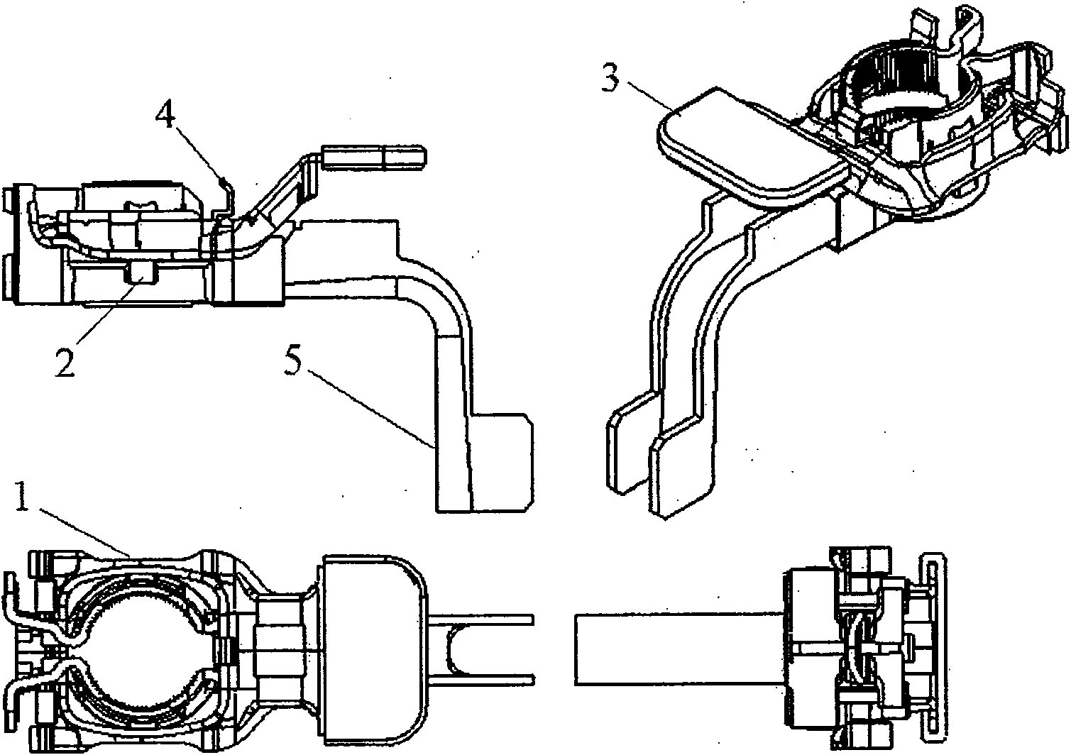
图1:蓄电池夹头总成图;Figure 1: Assembly drawing of the battery chuck;
图2:蓄电池夹头2D结构图;Figure 2: 2D structure diagram of the battery chuck;
图3:上锁紧支架结构图;Figure 3: Structural diagram of the upper locking bracket;
图4:下锁紧支架结构图;Figure 4: Structural diagram of the lower locking bracket;
图5:塑料护套结构图;Figure 5: Structural diagram of the plastic sheath;
图6:二次锁紧机构结构图;Figure 6: Structural diagram of the secondary locking mechanism;
图7:底座结构图;Figure 7: Base structure diagram;
图8:蓄电池夹头松开时的结构示意图。Figure 8: Schematic diagram of the structure when the battery clamp is loosened.
附图标记说明:Explanation of reference signs:
1-上锁紧支架 2-下锁紧支架 3-塑料护套 4-二次锁紧机构1-Upper locking bracket 2-Lower locking bracket 3-Plastic sheath 4-Secondary locking mechanism
5-底座 6-托起结构 7-支撑结构 8-圆环状结构5-base 6-supporting structure 7-supporting structure 8-circular structure
9-定位孔 10-折弯结构 11-底座的圆环9-Positioning hole 10-Bending structure 11-The ring of the base
12-波浪状结构 13-压接线束的结构 14-锁紧孔; 15-Y状结构;12-Wave-shaped structure 13-Crimping wiring harness structure 14-Locking hole; 15-Y-shaped structure;
具体实施方式Detailed ways
如图1、2所示,蓄电池夹头主要由5个部分组成:上锁紧支架1、下锁紧支架2、塑料护套3、二次锁紧机构4、以及底座5。利用金属之间的相互作用实现对蓄电池桩头的夹紧和放松。As shown in Figures 1 and 2, the battery chuck is mainly composed of five parts: an
在蓄电池夹头压紧时,由于上锁紧支架1上设计了两个托起结构6,以此作为下压上锁紧支架1的支点,降低了下压力矩。在上锁紧支架1压到下锁紧支架2上的圆环状结构8时,迫使下锁紧支架2收缩,进而压迫底座5收缩,达到压紧蓄电池桩头的目的。同时在上锁紧支架1下压时,其锁紧孔1 4刚好通过二次锁紧机构4(二次锁紧机构的材料是钢材),当上锁紧支架1压到底时,二次锁紧机构4上的折弯结构10压在上锁紧支架1上,起到二次锁紧的作用。When the battery chuck is pressed tightly, since two holding structures 6 are designed on the
在蓄电池夹头松开时,需要先拨开二次锁紧机构4,同时上提上锁紧支架1,由于上锁紧支架1上设计了一个支撑结构7,以此作为上提上锁紧支架1的支点,降低了上提力矩。在上锁紧支架1上提时,因为下锁紧支架2采用的是具有自恢复能力的材料,当超出下锁紧支架2上圆环状结构8时,下锁紧支架2恢复原来形状,对底座5的压迫力消除,从而使蓄电池夹头松开。When the battery chuck is loosened, the
下面结合各个部件的结构图进一步阐述本发明的设计思想:Further elaborate the design idea of the present invention below in conjunction with the structural diagram of each component:
如图3,是蓄电池夹头的上锁紧支架示意图,在上锁紧支架1两侧分别设计了一个类似十字架状的托起结构6,并在中间做出一个支撑结构7,从而借助杠杆原理,降低压紧或者提开的力矩。As shown in Figure 3, it is a schematic diagram of the upper locking bracket of the battery chuck. A cross-like holding structure 6 is designed on both sides of the
如图4,是蓄电池夹头的下锁紧支架示意图,在下锁紧支架2上设计了一个圆环状结构8,从而利用上锁紧支架1下压时的挤压,使下锁紧支架2收缩。产生对底座的收缩力,使底座收缩,从而紧紧地压接在蓄电池桩头上。下锁紧支架的材料具有良好的弹性,便于在上锁紧支架压接时收缩,松开时延展。As shown in Figure 4, it is a schematic diagram of the lower locking bracket of the battery chuck. A ring-shaped structure 8 is designed on the
如图5,是蓄电池夹头的塑料护套结构图,装配在上锁紧支架1上,保护操作时的人员安全,不会被金属刮伤。As shown in Figure 5, it is a structural diagram of the plastic sheath of the battery chuck, which is assembled on the
如图6,是蓄电池夹头的二次锁紧机构示意图,利用二次锁紧机构下端的两个定位孔9进行定位并与底座连接或者焊接在一起,通过二次锁紧机构上端的折弯结构10,依靠金属的弹性,压在上锁紧支架上。当需要打开时,只需拨开二次锁紧机构,将上锁禁支架向上提起即可,方便可靠。As shown in Figure 6, it is a schematic diagram of the secondary locking mechanism of the battery chuck. The two
如图7,是蓄电池夹头的底座结构图,在蓄电池夹头的底座的一侧,有一个Y状结构15,此结构与上锁紧支架1上的支撑结构7相配合,从而实现杠杆功能;底座上的圆环11是根据蓄电池桩头设计的,具有1/9的椎度,圆环11的大小也是与蓄电池桩头相吻合的,在圆环11的内侧还设计了波浪状结构12,用来增加与蓄电池桩头之间的摩擦力,从而确保蓄电池夹头压紧后不会发生转动、松脱,在一定的外力作用下不会发生断裂,确保与蓄电池桩头接触良好。在底座上有一个压接线束的结构13,确保线束与蓄电池桩头的连接方便性。对于蓄电池夹头的底座,需要直接与蓄电池的正极或者负极相连,因此要求其材料具有良好导电性能。As shown in Figure 7, it is the base structure diagram of the battery chuck. On one side of the base of the battery chuck, there is a Y-
图8是蓄电池夹头松开时的结构示意图。Fig. 8 is a structural schematic diagram when the battery clamp is loosened.
上述实施方案只是体现本发明技术方案的优选方案,本技术领域的技术人员对其中的某些部分所可能做出的一些变动均体现了本发明的原理,属于本发明的保护范围之内。The above-mentioned embodiments are only preferred solutions embodying the technical solution of the present invention, and some changes that may be made by those skilled in the art to some parts thereof reflect the principles of the present invention and fall within the scope of protection of the present invention.
Claims (6)
Priority Applications (1)
| Application Number | Priority Date | Filing Date | Title |
|---|---|---|---|
| CN2008100892817A CN101282000B (en) | 2008-04-25 | 2008-04-25 | A kind of automobile battery clamp |
Applications Claiming Priority (1)
| Application Number | Priority Date | Filing Date | Title |
|---|---|---|---|
| CN2008100892817A CN101282000B (en) | 2008-04-25 | 2008-04-25 | A kind of automobile battery clamp |
Publications (2)
| Publication Number | Publication Date |
|---|---|
| CN101282000A CN101282000A (en) | 2008-10-08 |
| CN101282000B true CN101282000B (en) | 2010-06-02 |
Family
ID=40014347
Family Applications (1)
| Application Number | Title | Priority Date | Filing Date |
|---|---|---|---|
| CN2008100892817A Active CN101282000B (en) | 2008-04-25 | 2008-04-25 | A kind of automobile battery clamp |
Country Status (1)
| Country | Link |
|---|---|
| CN (1) | CN101282000B (en) |
Families Citing this family (2)
| Publication number | Priority date | Publication date | Assignee | Title |
|---|---|---|---|---|
| CN104134775B (en) * | 2014-07-25 | 2017-01-18 | 安徽江淮汽车股份有限公司 | Battery positive post head protection box |
| CN109969110B (en) * | 2019-04-12 | 2021-08-27 | 李楠楠 | Self-adaptive adjustable storage battery clamp |
Citations (5)
| Publication number | Priority date | Publication date | Assignee | Title |
|---|---|---|---|---|
| CN1174421A (en) * | 1996-08-21 | 1998-02-25 | 住友电装株式会社 | Battery terminal |
| US5897403A (en) * | 1996-01-25 | 1999-04-27 | The Whitaker Corporation | Apparatus for making contact with a conical contact |
| US20020094728A1 (en) * | 2001-01-12 | 2002-07-18 | Hwan-Chang Kim | Connecting terminal for storage battery |
| CN1383230A (en) * | 2001-04-25 | 2002-12-04 | 梁世宗 | Improved structure of automobile battery chuck |
| CN2588547Y (en) * | 2002-04-23 | 2003-11-26 | 金焕昌 | Connection terminal for accumulator |
-
2008
- 2008-04-25 CN CN2008100892817A patent/CN101282000B/en active Active
Patent Citations (5)
| Publication number | Priority date | Publication date | Assignee | Title |
|---|---|---|---|---|
| US5897403A (en) * | 1996-01-25 | 1999-04-27 | The Whitaker Corporation | Apparatus for making contact with a conical contact |
| CN1174421A (en) * | 1996-08-21 | 1998-02-25 | 住友电装株式会社 | Battery terminal |
| US20020094728A1 (en) * | 2001-01-12 | 2002-07-18 | Hwan-Chang Kim | Connecting terminal for storage battery |
| CN1383230A (en) * | 2001-04-25 | 2002-12-04 | 梁世宗 | Improved structure of automobile battery chuck |
| CN2588547Y (en) * | 2002-04-23 | 2003-11-26 | 金焕昌 | Connection terminal for accumulator |
Also Published As
| Publication number | Publication date |
|---|---|
| CN101282000A (en) | 2008-10-08 |
Similar Documents
| Publication | Publication Date | Title |
|---|---|---|
| CN113879094B (en) | A heavy-duty truck battery replacement locking mechanism assembly | |
| CN118213701B (en) | Pressure relief device, battery and electrical equipment | |
| CN101282000A (en) | A kind of automobile battery clamp | |
| CN203843419U (en) | Compact self-locking mechanism | |
| JP2012014916A (en) | Flat plate type solid oxide fuel cell module | |
| CN201711727U (en) | Shock absorber oil cylinder assembly welding tool | |
| CN101838825B (en) | Emergency bus device used for aluminum electrolytic cell | |
| CN201122630Y (en) | Piling machine for fuel cell electric pile | |
| CN201655989U (en) | Wire quick locking structure | |
| CN201112464Y (en) | Automotive battery terminals | |
| CN211063323U (en) | Cable restraint fastener convenient to butt joint | |
| CN201095811Y (en) | Assembled steel bracket | |
| CN220796991U (en) | Unmanned aerial vehicle battery buckle device | |
| CN118769610A (en) | Fuel cell stack pressing mechanism, working method and stack pressing machine | |
| CN213959002U (en) | Fuel cell lower end plate with rubber structure | |
| CN201376510Y (en) | Clamp for connecting a contact wire and an electric connecting wire | |
| CN209389167U (en) | Electric car burn-out-proof vehicle battery automatic safety device | |
| CN218472177U (en) | Locking structure | |
| CN213989525U (en) | Hydraulic mechanism for connecting grounding belt | |
| CN206894575U (en) | A kind of solar telephone battery protector | |
| CN116742279B (en) | Welding-free energy storage battery system | |
| CN223451223U (en) | Power supply connection device and ladle car | |
| CN220400814U (en) | Energy storage battery pack | |
| CN222663164U (en) | A battery arrangement structure for electric vehicle | |
| CN118448801B (en) | Structure of new energy vehicle battery pack used for long time |
Legal Events
| Date | Code | Title | Description |
|---|---|---|---|
| C06 | Publication | ||
| PB01 | Publication | ||
| C10 | Entry into substantive examination | ||
| SE01 | Entry into force of request for substantive examination | ||
| C14 | Grant of patent or utility model | ||
| GR01 | Patent grant |