CN101299544A - Battery pack, battery charger and charging method - Google Patents
Battery pack, battery charger and charging method Download PDFInfo
- Publication number
- CN101299544A CN101299544A CNA2008100852858A CN200810085285A CN101299544A CN 101299544 A CN101299544 A CN 101299544A CN A2008100852858 A CNA2008100852858 A CN A2008100852858A CN 200810085285 A CN200810085285 A CN 200810085285A CN 101299544 A CN101299544 A CN 101299544A
- Authority
- CN
- China
- Prior art keywords
- battery pack
- charging
- battery
- voltage
- timeout period
- Prior art date
- Legal status (The legal status is an assumption and is not a legal conclusion. Google has not performed a legal analysis and makes no representation as to the accuracy of the status listed.)
- Pending
Links
Images


Classifications
-
- H—ELECTRICITY
- H01—ELECTRIC ELEMENTS
- H01M—PROCESSES OR MEANS, e.g. BATTERIES, FOR THE DIRECT CONVERSION OF CHEMICAL ENERGY INTO ELECTRICAL ENERGY
- H01M10/00—Secondary cells; Manufacture thereof
- H01M10/42—Methods or arrangements for servicing or maintenance of secondary cells or secondary half-cells
- H01M10/44—Methods for charging or discharging
-
- H—ELECTRICITY
- H02—GENERATION; CONVERSION OR DISTRIBUTION OF ELECTRIC POWER
- H02J—ELECTRIC POWER NETWORKS; CIRCUIT ARRANGEMENTS OR SYSTEMS FOR SUPPLYING OR DISTRIBUTING ELECTRIC POWER; SYSTEMS FOR STORING ELECTRIC ENERGY
- H02J7/00—Circuit arrangements for charging or discharging batteries or for supplying loads from batteries
- H02J7/90—Regulation of charging or discharging current or voltage
- H02J7/92—Regulation of charging or discharging current or voltage with prioritisation of loads or sources
-
- Y—GENERAL TAGGING OF NEW TECHNOLOGICAL DEVELOPMENTS; GENERAL TAGGING OF CROSS-SECTIONAL TECHNOLOGIES SPANNING OVER SEVERAL SECTIONS OF THE IPC; TECHNICAL SUBJECTS COVERED BY FORMER USPC CROSS-REFERENCE ART COLLECTIONS [XRACs] AND DIGESTS
- Y02—TECHNOLOGIES OR APPLICATIONS FOR MITIGATION OR ADAPTATION AGAINST CLIMATE CHANGE
- Y02E—REDUCTION OF GREENHOUSE GAS [GHG] EMISSIONS, RELATED TO ENERGY GENERATION, TRANSMISSION OR DISTRIBUTION
- Y02E60/00—Enabling technologies; Technologies with a potential or indirect contribution to GHG emissions mitigation
- Y02E60/10—Energy storage using batteries
Landscapes
- Engineering & Computer Science (AREA)
- Power Engineering (AREA)
- Manufacturing & Machinery (AREA)
- Chemical & Material Sciences (AREA)
- Chemical Kinetics & Catalysis (AREA)
- Electrochemistry (AREA)
- General Chemical & Material Sciences (AREA)
- Charge And Discharge Circuits For Batteries Or The Like (AREA)
- Secondary Cells (AREA)
Abstract
提供电池组、电池充电器以及用于对电池组充电的方法。该电池组包括:充电电池;开关元件,用于控制该充电电池的充电和放电;控制器,用于控制该开关元件;以及通信单元,用于执行与电池充电器的通信。在充电期间,当充电电池的电压达到预定电压时,将初始充电切换到快速充电,而当在开始初始充电之后的超时时段内该电压没有达到预定电压,电池充电器将电池组判断为反常。存储超时时段和预定电压至少之一。将读出的超时时段和预定电压至少之一通过通信单元传送到电池充电器。
A battery pack, a battery charger, and a method for charging the battery pack are provided. The battery pack includes: a rechargeable battery; a switching element for controlling charging and discharging of the rechargeable battery; a controller for controlling the switching element; and a communication unit for performing communication with a battery charger. During charging, when the voltage of the rechargeable battery reaches a predetermined voltage, the initial charging is switched to quick charging, and when the voltage does not reach the predetermined voltage within a timeout period after starting the initial charging, the battery charger judges the battery pack as abnormal. At least one of a timeout period and a predetermined voltage is stored. At least one of the read timeout period and the predetermined voltage is transmitted to the battery charger through the communication unit.
Description
相关申请交叉参考Related Application Cross Reference
本申请要求于2007年3月9日提交到日本专利局的日本专利申请第2007-61060号的优先权益,该申请的全部内容通过引用合并在此。This application claims priority benefit from Japanese Patent Application No. 2007-61060 filed with the Japan Patent Office on March 9, 2007, the entire contents of which are hereby incorporated by reference.
技术领域 technical field
本发明涉及具有充电电池(secondary battery)的电池组、电池充电器以及用于充电该电池组的充电方法。The present invention relates to a battery pack with a secondary battery, a battery charger and a charging method for charging the battery pack.
背景技术 Background technique
最近,诸如笔记本型PC(个人计算机)、蜂窝式电话和PDA(个人数字助理)之类的便携电器设备已经广泛流行,作为其电源,使用具有高电压、高能量密度和轻重量优势的锂离子充电电池的电池组也已经广泛使用。相应于要使用的设备和目的制造具有不同容量、不同充电率的这些电池组。在该说明书中,术语“电池组”指的是这样的一些东西,在其中,充电电池、用于控制该充电电池的充电或放电的电路部分以及用于执行与电池充电器的通信的通信单元被集成到单一装置中。Recently, portable electric devices such as notebook PCs (Personal Computers), cellular phones, and PDAs (Personal Digital Assistants) have become widely popular, and as their power sources, lithium-ion lithium batteries, which have the advantages of high voltage, high energy density, and light weight, have been used. Battery packs of rechargeable batteries have also been widely used. These battery packs are manufactured with different capacities and different charging rates corresponding to the equipment and purpose to be used. In this specification, the term "battery pack" refers to something in which a rechargeable battery, a circuit part for controlling charging or discharging of the rechargeable battery, and a communication unit for performing communication with a battery charger are integrated into a single device.
按照惯例,用于充电电池组的相应电池充电器根据诸如电池组的容量和充电率之类的特性进行制造。如果每当制造新电池充电器时都制造适配于所述特性的电器充电器,将会增加制造成本。此外,如果具有实质上相同的外形和不同特性的电池组连接到不适配于该电池组的电池充电器,则可能显现出诸如发热或燃烧之类的潜在危险情况。Conventionally, a corresponding battery charger for charging a battery pack is manufactured according to characteristics such as the capacity and charge rate of the battery pack. If an appliance charger adapted to the characteristics is manufactured every time a new battery charger is manufactured, the manufacturing cost will increase. Furthermore, if a battery pack having substantially the same shape but different characteristics is connected to a battery charger not suitable for the battery pack, a potentially dangerous situation such as heating or burning may manifest.
因此,最近已经使用了能够执行充电以匹配多种类型的电池组的电池充电器。这种类型的电池充电器的使用消除了制造新充电器的必要,并且单一电池充电器可以对具有例如不同电池容量的电池组充电。能够充电多种类型的电池组的充电器通常被设计成能够对相应电池组中的低容量电池组和低充电率电池组充电。因此,例如,在充电期间从充电器流向电池组的充电电流被设计成低得匹配低容量电池组。Therefore, a battery charger capable of performing charging to match various types of battery packs has recently been used. The use of this type of battery charger eliminates the need to manufacture a new charger, and a single battery charger can charge battery packs having, for example, different battery capacities. A charger capable of charging multiple types of battery packs is generally designed to be able to charge a low-capacity battery pack and a low-charge-rate battery pack among the corresponding battery packs. Thus, for example, the charging current flowing from the charger to the battery pack during charging is designed to be low enough to match a low capacity battery pack.
作为诸如锂离子充电电池之类的充电电池的快速充电模式,使用作为恒流充电和恒压充电的组合的CCCV(恒流恒压)充电模式。在CCCV充电模式下,如图9所示,以恒流进行充电,直到电池组的电池电压达到预定电压为止,并且在达到预定电压之后,以恒压进行充电。在充电电流已经会聚到基本上是零安培的时刻(point)终止充电。As a quick charging mode of a rechargeable battery such as a lithium ion rechargeable battery, a CCCV (Constant Current Constant Voltage) charging mode that is a combination of constant current charging and constant voltage charging is used. In the CCCV charging mode, as shown in FIG. 9 , charging is performed at a constant current until the battery voltage of the battery pack reaches a predetermined voltage, and after reaching the predetermined voltage, charging is performed at a constant voltage. Charging is terminated at the point at which the charging current has converged to substantially zero amperes.
例如,在电池电压V为4.1V或以下的范围内,以A=500mA执行恒流充电。当充电电池的电池电压(内电动势)因充电而增加并且电池电压V变成大于4.1V时,充电电源部分的操作被切换到恒压控制,而充电电流A逐渐减小。电池电压V朝着电源部分的输出电压(4.2V)增加。随后,当充电电流基本上接近零时,完成充电。作为检测充电完成的方法,熟知电流检测方法和ΔV检测方法。For example, constant current charging is performed at A=500 mA in the range where the battery voltage V is 4.1 V or less. When the battery voltage (internal electromotive force) of the rechargeable battery increases due to charging and the battery voltage V becomes greater than 4.1V, the operation of the charging power supply section is switched to constant voltage control, and the charging current A gradually decreases. The battery voltage V increases toward the output voltage (4.2V) of the power supply section. Subsequently, charging is complete when the charging current is substantially close to zero. As a method of detecting completion of charging, a current detection method and a ΔV detection method are well known.
通常,当对高容量电池组进行快速充电时,可以以比低容量电池组的充电电流高的充电电流对电池组充电。然而,当使用能够充电多种类型的电池组的常规电池充电器对高容量电池组充电时,以预设到充电器的、用于对低容量电池组充电的低充电电流进行充电。因此,如果对高容量电池组充电,则恒流充电时段变长,因而将花很多时间来充电。Generally, when fast charging a high-capacity battery pack, the battery pack can be charged at a higher charging current than that of a low-capacity battery pack. However, when a high-capacity battery pack is charged using a conventional battery charger capable of charging various types of battery packs, charging is performed at a low charging current preset to the charger for charging a low-capacity battery pack. Therefore, if a high-capacity battery pack is charged, the constant current charging period becomes long, so it will take a lot of time to charge.
也就是说,当用常规电池充电器对高容量电池组或高充电率电池组充电时,充电可能不完全满足其特性,从而引起花很多充电时间的问题。That is, when a high-capacity battery pack or a high-charging-rate battery pack is charged with a conventional battery charger, the charging may not fully satisfy its characteristics, causing a problem that it takes a lot of charging time.
为了解决上述问题,例如,如在日本未审专利申请公开第9-285026号(以下称为“专利文献1”)所述,已经提出了能够通过根据电池组的特性改变充电电流来正确地充电相应电池组的电池充电器。专利文献1所述的电池充电器从相应电池组获得例如关于最大充电电流和最大充电电压的信息。该电池充电器被设计成基于所获得的、关于最大充电电流和最大充电电压的信息来在恒流时段改变充电电流。In order to solve the above-mentioned problems, for example, as described in Japanese Unexamined Patent Application Publication No. 9-285026 (hereinafter referred to as "
具体地说,如图11所示,设置成以高于低容量电池组的充电电流的电流值在高容量电池组的恒流时段中通过电流。这使得能够正确地对高容量电池组进行充电,从而比用常规电池充电器充电减少充电时间。Specifically, as shown in FIG. 11 , it is set to pass a current in the constant current period of the high-capacity battery pack at a current value higher than the charging current of the low-capacity battery pack. This enables the correct charging of high capacity battery packs, reducing charging time compared to charging with conventional battery chargers.
因此,具有不同特性的电池组可以正确地充电,并且可以通过基于从相应电池组获得的最大充电电流的信息改变充电电流来减少充电时间。Therefore, battery packs having different characteristics can be correctly charged, and the charging time can be reduced by changing the charging current based on the information of the maximum charging current obtained from the corresponding battery pack.
发明内容Contents of the invention
同时,当正常充电电流通过在电池组的电池电压低于预定电压的条件下进行快速充电流过电池组时,可能引起诸如发热之类的反常事件(abnormalevent)。由于此原因,通常在快速充电之前例如100mA至200mA这样小的充电电流流过电池组,以便初始充电继续,直到电池组的电池电压达到预定电压为止。Meanwhile, when a normal charging current flows through the battery pack by performing quick charging under the condition that the battery voltage of the battery pack is lower than a predetermined voltage, abnormal events such as heat generation may be caused. For this reason, generally, a small charging current such as 100 mA to 200 mA flows through the battery pack before fast charging, so that the initial charging continues until the battery voltage of the battery pack reaches a predetermined voltage.
给电池充电器预设预定电压(以下在某些情况下称为“切换电压(switching voltage)”),作为用于将充电模式从初始充电切换到快速充电的电压阈值。当在初始充电期间电池组的电池电压达到切换电压时,开始快速充电。电池充电器配备设置超时时段的计时器。也就是说,当电池组的电池电压在预定时段中没有达到切换电压时,基于超时时段,将电池组判断为反常并停止充电。A predetermined voltage (hereinafter referred to as a "switching voltage" in some cases) is preset to the battery charger as a voltage threshold for switching the charging mode from initial charging to rapid charging. When the battery voltage of the battery pack reaches the switching voltage during initial charging, fast charging starts. The battery charger is equipped with a timer to set the timeout period. That is, when the battery voltage of the battery pack does not reach the switching voltage within a predetermined period, based on the timeout period, the battery pack is judged to be abnormal and charging is stopped.
现在考虑使用常规电池充电高容量电池组的情况。电池组被设置到例如超时时段以及切换电压,以匹配常规低容量电池组。Now consider the case of using conventional cells to charge a high capacity battery pack. The battery pack is set to eg timeout periods and switching voltages to match conventional low capacity battery packs.
如图12所示,高容量电池组与低容量电池组相比具有较低速度的电压上升,因此它花很多时间,直到电池组的电池电压达到切换电压为止,并且它可能超过设置到电池充电器的计时器的超时时段。因此,在这种情况下,即使高容量电池组处于正常状态,电池组也可能被判断为电池组反常,并且充电也可能被停止。As shown in Figure 12, a high-capacity battery pack has a lower speed of voltage rise than a low-capacity battery pack, so it takes a lot of time until the battery voltage of the battery pack reaches the switching voltage, and it may exceed the setting to charge the battery The timeout period of the timer's timer. Therefore, in this case, even if the high-capacity battery pack is in a normal state, the battery pack may be judged to be abnormal, and charging may be stopped.
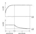
也存在具有高性能的电池组,通过改变例如电极中使用的材料,其能够放电达到比常规电池组更低的电压(如图13所示)。高性能电池组能够放电达到比常规电池组更低的电压,从而使得汲取更多放电量成为可能。There are also batteries with high performance that can be discharged to lower voltages than conventional batteries by changing eg the materials used in the electrodes (as shown in Figure 13). High-performance battery packs are able to discharge to lower voltages than conventional battery packs, making it possible to draw more discharge capacity.
与以上提到的高容量电池组一样,通过改善性能而获得的高容量电池组具有比低容量电池组更低速度的电压上升。因此,当由其切换电压被设置成匹配常规电池组的电池充电器执行充电时,即使电池组处于正常状态,充电控制处理器也可能判断为反常,并且因为所测量的时间超过超时时段而停止充电。As with the above-mentioned high-capacity battery pack, the high-capacity battery pack obtained by improving performance has a lower rate of voltage rise than the low-capacity battery pack. Therefore, when charging is performed by a battery charger whose switching voltage is set to match a conventional battery pack, even if the battery pack is in a normal state, the charging control processor may judge it as abnormal and stop because the measured time exceeds the timeout period Charge.
高性能电池组也可以从比常规电池组更低的电压执行快速充电。当高性能电池组由设置了允许从初始充电切换到快速充电的切换电压以匹配常规电池组的常规电池充电器进行充电时,电池组的电池电压可能需要更长的充电时间,原因是初始充电即使在电池组的电池电压达到能够切换到快速充电的电压之后仍然继续,如图14中所示。High-performance battery packs can also perform fast charging from a lower voltage than conventional battery packs. When a high-performance battery pack is charged by a conventional battery charger set to match the switching voltage from initial charging to fast charging to match a conventional battery pack, the battery voltage of the battery pack may take longer to charge due to initial charging Continues even after the battery pack's cell voltage reaches a voltage at which it can switch to fast charging, as shown in FIG. 14 .
因此,在常规电池充电器中,将与从初始充电到快速充电的切换相关的超时时段和切换电压设置成匹配低容量电池组,从而使得正确充电高容量电池组和高充电率电池组很困难。Therefore, in conventional battery chargers, the timeout periods and switching voltages associated with switching from initial charging to fast charging are set to match low-capacity battery packs, making it difficult to properly charge high-capacity battery packs and high-charge-rate battery packs .
最好提供这样的电池组、电池充电器和充电该电池组的方法,其被设计成正确地对多种类型的电池组进行充电。It would be desirable to provide a battery pack, battery charger, and method of charging the battery pack that are designed to properly charge multiple types of battery packs.
根据本发明的实施方式,提供电池组,其包括:充电电池;开关元件,用于控制该充电电池的充电和放电;控制器,用于控制开关元件;以及通信单元,用于执行与电池充电器的通信。在充电期间,当充电电池的电压达到预定电压时,初始充电被切换到快速充电,而当在开始初始充电之后的超时时段内电压没有达到预定电压时,电池充电器将电池组判断为反常。存储超时时段和预定电压中的至少之一。将读出的超时时段和预定电压中的至少之一经由通信单元传送到电池充电器。According to an embodiment of the present invention, there is provided a battery pack including: a rechargeable battery; a switching element for controlling charging and discharging of the rechargeable battery; a controller for controlling the switching element; and a communication unit for performing charging with the battery. device communication. During charging, when the voltage of the rechargeable battery reaches a predetermined voltage, the initial charging is switched to quick charging, and when the voltage does not reach the predetermined voltage within a timeout period after starting the initial charging, the battery charger judges the battery pack as abnormal. At least one of a timeout period and a predetermined voltage is stored. At least one of the read timeout period and the predetermined voltage is transmitted to the battery charger via the communication unit.
根据本发明的另一实施方式,提供用于电池组的电池充电器,其包括:通信单元和充电控制器。通信单元执行与电池组的通信并从电池组接收关于超时时段的信息。在充电期间,充电控制器执行电池组的初始充电,当电池组的电压达到预定电压时执行快速充电,而当在开始初始充电之后的超时时段内电压没有达到预定电压时将电池组判断为反常。According to another embodiment of the present invention, there is provided a battery charger for a battery pack, which includes: a communication unit and a charge controller. The communication unit performs communication with the battery pack and receives information about a timeout period from the battery pack. During charging, the charge controller performs initial charging of the battery pack, performs quick charging when the voltage of the battery pack reaches a predetermined voltage, and judges the battery pack as abnormal when the voltage does not reach the predetermined voltage within a timeout period after starting initial charging .
充电根据本发明的电池组的方法基于关于从电池组接收到的超时时段的信息进行判断。The method of charging the battery pack according to the present invention judges based on the information about the time-out period received from the battery pack.
根据本发明的其它实施方式,提供用于电池组的电池充电器,其包括:通信单元和充电控制器。通信单元执行与电池组的通信并从电池组接收关于充电电池的满充电容量值(full charge capacity value)的信息。充电控制器基于关于该满充电容量值的信息计算超时时段,并且在充电期间执行电池组的初始充电,当电池组的电压达到预定电压时执行快速充电,而当在开始初始充电之后的超时时段内电压没有达到预定电压时将电池组判断为反常。According to other embodiments of the present invention, there is provided a battery charger for a battery pack including: a communication unit and a charge controller. The communication unit performs communication with the battery pack and receives information on a full charge capacity value of the rechargeable battery from the battery pack. The charge controller calculates a timeout period based on the information on the full charge capacity value, and performs initial charging of the battery pack during charging, quick charging when the voltage of the battery pack reaches a predetermined voltage, and when the timeout period after starting the initial charging When the internal voltage does not reach the predetermined voltage, the battery pack is judged as abnormal.
充电根据本发明的其它实施方式的电池组的方法包括步骤:基于关于从电池组接收到的满充电容量值的信息计算超时时段;以及基于所计算出来的超时时段做出判断。A method of charging a battery pack according to other embodiments of the present invention includes the steps of: calculating a timeout period based on information on a full charge capacity value received from the battery pack; and making a judgment based on the calculated timeout period.
根据本发明的进一步的其它实施方式,提供用于电池组的电池充电器,其包括通信单元和充电控制器。通信单元执行与电池组的通信并从电池组接收关于预定电压的信息。充电控制器在充电期间执行电池组的初始充电,当电池组的电压达到预定电压时执行快速充电,而当在开始初始充电之后的超时时段内电压没有达到预定电压时将电池组判断为反常。According to still other embodiments of the present invention, there is provided a battery charger for a battery pack including a communication unit and a charge controller. The communication unit performs communication with the battery pack and receives information on a predetermined voltage from the battery pack. The charging controller performs initial charging of the battery pack during charging, performs quick charging when the voltage of the battery pack reaches a predetermined voltage, and judges the battery pack as abnormal when the voltage does not reach the predetermined voltage within a timeout period after starting the initial charging.
根据本发明的进一步的其它实施方式,提供充电方法,其包括步骤:基于从电池组接收到的预定电压的信息判断电池组是否反常。According to still other embodiments of the present invention, there is provided a charging method including the step of: judging whether the battery pack is abnormal based on information of a predetermined voltage received from the battery pack.
因此,根据本发明的实施方式,电池组向电池充电器侧提供关于超时时段的信息,以便电池充电器侧能够使用正确的超时时段判断电池组在初始充电期间是否反常。此外,所提供的电池组向电池充电器侧通告关于预定电压的信息,以便电池充电器侧可以使用正确的预定电压控制初始充电和快速充电之间的切换。Therefore, according to an embodiment of the present invention, the battery pack provides information on the timeout period to the battery charger side, so that the battery charger side can use the correct timeout period to judge whether the battery pack is abnormal during initial charging. In addition, the provided battery pack notifies information about the predetermined voltage to the battery charger side, so that the battery charger side can control switching between initial charging and quick charging using the correct predetermined voltage.
根据本发明的实施方式,配置成相应于充电电池的类型地正确设置超时时段,凭此对该充电电池正确充电。因此,能够防止由于尽管事实是正常而被判断为反常导致停止充电。According to an embodiment of the present invention, it is configured to correctly set the time-out period corresponding to the type of the rechargeable battery, whereby the rechargeable battery is correctly charged. Therefore, it is possible to prevent charging from being stopped due to being judged as abnormal despite the fact that it is normal.
此外,根据本发明的实施方式,配置成相应于充电电池的类型地正确设置允许从初始充电到快速充电的切换的预定电压,凭此对充电电池正确充电并减少充电时间。Furthermore, according to an embodiment of the present invention, it is configured to correctly set a predetermined voltage allowing switching from initial charging to quick charging corresponding to the type of the secondary battery, whereby the secondary battery is correctly charged and the charging time is reduced.
附图说明 Description of drawings
图1是示出根据本发明的第一实施方式的电池充电器的示例的配置的方框图;1 is a block diagram showing the configuration of an example of a battery charger according to a first embodiment of the present invention;
图2是解释相应于电池组的充电特性的超时时段设置的替代的示意图;FIG. 2 is a schematic diagram explaining an alternative setting of a time-out period corresponding to a charging characteristic of a battery pack;
图3是解释根据第一实施方式的电池充电器的充电处理的流程的流程图;3 is a flowchart explaining the flow of charging processing of the battery charger according to the first embodiment;
图4是解释根据本发明的第二实施方式的电池充电器的充电处理的流程的流程图;4 is a flow chart explaining the flow of charging processing of the battery charger according to the second embodiment of the present invention;
图5是解释根据本发明的第三实施方式的电池充电器的充电处理的流程的流程图;5 is a flowchart explaining the flow of charging processing of the battery charger according to the third embodiment of the present invention;
图6是解释相应于电池组的充电特性的切换电压设置的替代的示意图;FIG. 6 is a schematic diagram explaining an alternative of switching voltage settings corresponding to charging characteristics of a battery pack;
图7是解释根据本发明的第四实施方式的电池充电器的充电处理的流程的流程图;7 is a flowchart explaining the flow of charging processing of the battery charger according to the fourth embodiment of the present invention;
图8是解释根据本发明的第五实施方式的电池充电器的充电处理的流程的流程图;8 is a flowchart explaining the flow of charging processing of the battery charger according to the fifth embodiment of the present invention;
图9是示出CCCV充电模式的充电特性的示例的示意图;9 is a schematic diagram showing an example of charging characteristics of a CCCV charging mode;
图10是解释低容量电池组和高容量电池组都由常规电池充电器充电的情况的示意图;FIG. 10 is a schematic diagram for explaining a case where both a low-capacity battery pack and a high-capacity battery pack are charged by a conventional battery charger;
图11是解释相应于电池组的充电特性的充电电流设置的替代的示意图;FIG. 11 is a schematic diagram explaining alternatives to charging current settings corresponding to charging characteristics of a battery pack;
图12是解释从初始充电到快速充电的切换的示意图;FIG. 12 is a schematic diagram explaining switching from initial charging to fast charging;
图13是解释电池组的放电特性的示意图;以及FIG. 13 is a schematic diagram for explaining discharge characteristics of a battery pack; and
图14是解释从初始充电到快速充电的切换的另一示意图。FIG. 14 is another schematic diagram explaining switching from initial charging to quick charging.
具体实施方式 Detailed ways
下面将描述本发明的第一实施方式。在该第一实施方式中,由电池充电器对具有锂离子充电电池的电池组充电,并且将CCCV充电模式用作快速充电模式。将初始充电作为快速充电的之前阶段执行。在充电期间,当充电电池的电压(电池组的输出电压)达到作为阈值的切换电压时,将充电模式从初始充电切换到快速充电。当它在开始初始充电之后的超时时段内没有达到切换电压时,电池充电器将电池组判断为反常。超时时段指示直到达到允许从初始充电到快速充电的切换的切换电压为止的时间限制。超时时段根据电池组的类型改变,凭此正确地充电该电池组。A first embodiment of the present invention will be described below. In this first embodiment, a battery pack with lithium-ion rechargeable cells is charged by a battery charger, and the CCCV charging mode is used as the fast charging mode. Perform initial charging as a preceding phase of fast charging. During charging, when the voltage of the rechargeable battery (the output voltage of the battery pack) reaches the switching voltage as a threshold, the charging mode is switched from initial charging to quick charging. The battery charger judges the battery pack as abnormal when it does not reach the switching voltage within a timeout period after starting initial charging. The timeout period indicates the time limit until reaching the switching voltage that allows switching from initial charging to fast charging. The timeout period varies according to the type of battery pack by which the battery pack is properly charged.
将参考图1描述第一实施方式中的电池充电器1的配置的示例。电池充电器1具有电源提供端2、电源电路3、充电控制器4和恒流恒压控制器5。在电池组10连接时,电池组10被充电。电池组10具有:诸如锂离子充电电池之类的充电电池;诸如FET之类的开关元件,用于在充电电池的充电期间控制放电;控制器,用于控制开关元件;以及通信单元,用于执行与电池充电器的通信。该控制器有微处理器组成。该电池组10也具有诸如EEPROM(电可擦可编程只读存储器)之类的非易失性存储器,并且在该非易失性存储器中存储适合于充电电池的超时时段。An example of the configuration of the
电池充电器1的电源提供端2例如是连接到家用AC电源的外部电源的出口,向电源电路3提供AC电源。电源电路3主要由输入滤波器21、整流电路22、变压器23、整流电路24和PWM(脉宽调制)控制电路25组成。电源3将电源提供端2提供的AC电源转换成用于对电池组10充电的DC电源。The
电池充电器控制器4通过控制逆流防止开关6和充电开关7来执行所连电池组10的充电控制,其中逆流防止开关6用于在充电期间防止电流反向流动,而充电开关7用于开/关充电。充电控制器4也每预定时段检测一次电池组10的电池电压。充电控制器4主要由存储器11、CPU(中央处理单元)12、计时器13和通信单元14组成。The
存储器11包括诸如EEPROM之类的非易失性存储器和可写存储器两者。非易失性存储器存储事先作为初始值的超时时段,以及指示允许从初始充电到快速充电的切换的电池电压的切换电压。该非易失性存储器也存储从连接到存储器11的电池组10获得的超时时段。代替在电池充电器1中存储初始值,可以在电池充电器1的存储器中存储从电池组10传送来的超时时段和切换电压。The
在事先存储在ROM(只读存储器,未示出)中的程序下,CPU 12使用诸如工作存储器之类的RAM(随机存取存储器,未示出)控制相应部分。CPU12经由通信单元14从所连接的电池组10获得超时时段,并将其设置到计时器13。当所测定的时间达到超时时段时,计时器13向CPU 12提供超时判断输出。CPU 12进一步读取存储在存储器11中的切换电压,并将其与所检测到的电池组10的电池电压进行比较。The
为了从电池组10接收关于超时时段的信息,通信单元14执行与所连接的电池组10的有线或无线通信,然后将该信息提供给CPU 12。In order to receive information on the time-out period from the
恒流恒压控制器5检测关于电池组10的充电电压和充电电流,并基于检测结果来控制电源电路3以便正确充电电池组10。The constant current
下面将描述根据第一实施方式的充电方法。如背景技术部分所述,高容量电池组在初始充电期间具有比低容量电池组更小程度的电池电压上升,从而达到允许从初始充电到快速充电的切换的切换电压需要更长时间。当高容量电池组由相应于低容量电池组的超时时段被设置到的电池充电器进行充电时,高容量电池组的电池电压不能在超时时段内达到切换电压。因此,高容量电池组尽管处于正常状态但仍有可能被判断为反常,这导致完成充电很困难。The charging method according to the first embodiment will be described below. As mentioned in the background section, high capacity battery packs have a lesser degree of battery voltage rise during initial charging than low capacity battery packs, thus taking longer to reach the switching voltage that allows switching from initial charging to fast charging. When the high-capacity battery pack is charged by the battery charger to which the time-out period corresponding to the low-capacity battery pack is set, the battery voltage of the high-capacity battery pack cannot reach the switching voltage within the time-out period. Therefore, a high-capacity battery pack may be judged as abnormal despite being in a normal state, which makes it difficult to complete charging.
由于这个原因,在第一实施方式中,超时时段被改变成适合高容量电池组的超时时段,以便可以正确地对高容量电池组充电。For this reason, in the first embodiment, the time-out period is changed to a time-out period suitable for the high-capacity battery pack so that the high-capacity battery pack can be charged correctly.
例如,如图2所示,考虑用其超时时段被预设在从一个点a起过去预定时间的点aout处的电池充电器对高容量电池组B充电的情况,其中该点a指示低容量电池组A达到切换电压的时间(以后在某些情况下称为切换时间)。For example, as shown in FIG. 2, consider a case where a high-capacity battery pack B is charged with a battery charger whose time-out period is preset at a point a out at which a predetermined time elapses from a point a indicating a low The time when the capacity battery pack A reaches the switching voltage (hereinafter referred to as the switching time in some cases).
当高容量电池组B连接到电池充电器时,电池充电器从电池组B获得超时时段,并将其重新设置到计时器。因此,新超时时段被设置在点bout,即从指示电池组B的切换时间的点b起过去预定时间的点。这使得电池组B能够正确充电,并且也使得正常初始充电能够进行,直到电池组B的电池电压达到切换电压。When high-capacity battery pack B is connected to the battery charger, the battery charger gets the timeout period from battery pack B and resets it to the timer. Therefore, a new time-out period is set at point b out , that is, a point at which a predetermined time has elapsed from point b indicating the switching time of the battery pack B. As shown in FIG. This enables battery pack B to be charged correctly, and also enables normal initial charging until the battery voltage of battery pack B reaches the switching voltage.
将参考图3的流程图描述第一实施方式中的电池充电器1的充电处理的过程。除非另有声明,否则,下列处理是在CPU 12的控制下执行。The procedure of the charging process of the
在电池组10连接到电池充电器1然后检测电池组10的条件下开始充电处理。在步骤S11,开始初始充电,计时器13开始时间测量。在步骤S12,将作为基准存储在存储器11中的超时时段设置到计时器13。同时执行初始充电的开始和超时时段的设置。The charging process starts under the condition that the
在步骤S13,其判断计时器13的测量时间是否达到所设置的超时时段。如果所测量到的时间达到超时时段,则计时器13产生指示这种情况的输出信号。如果判断为计时器13的测量时间没有达到超时时段,则该过程前进到步骤S14。另一方面,如果判断为计时器13的测量值达到超时时段,则将电池组10判断为反常,并终止一系列处理。In step S13, it is judged whether the measurement time of the
在步骤S14,其判断与电池组10通信是否成为可能。如果判断为与电池组10通信成为可能,则过程继续到步骤S15。在步骤S15,开始与电池组10的通信。在步骤S16,从电池组10获得关于超时时段的信息,并将其作为新超时时段设置到计时器13。另一方面,如果判断为不能与电池组10通信,则过程返回到步骤S13。In step S14, it is judged whether or not communication with the
在步骤S17,通过检测电池组10的电池电压并将所检测到的电池组10的电池电压与预设的切换电压比较,来判断电池组10的电池电压是否达到切换电压。如果判断为电池组10的电池电压达到切换电压,则过程继续到步骤S18。另一方面,如果判断为电池组10的电池电压没有达到切换电压,则过程返回到步骤S13。In step S17, it is determined whether the battery voltage of the
在步骤S18,将充电模式从初始充电切换到快速充电,并开始快速充电。在步骤S19,通过检测电池组10的电池电压并将所检测到的电池组10的电池电压与电池充电器的输出电压比较,来判断充电是否完成。如果判断为充电完成,则终止一系列处理。另一方面,如果判断充电没有完成,则过程返回到步骤S18。作为替换,充电的完成可以根据充电电流来检测。In step S18, switch the charging mode from initial charging to fast charging, and start fast charging. In step S19, whether charging is completed or not is judged by detecting the battery voltage of the
在步骤S13判断其是否达到超时时段的处理可以在步骤S16和步骤S17之间执行。作为步骤S17的处理的结果,这使得能够省略再次获得过程返回到步骤S13需要的超时时段的处理。The process of judging whether it has reached the time-out period at step S13 may be performed between steps S16 and S17. This makes it possible to omit the process of reacquiring the time-out period required for the process to return to step S13 as a result of the process of step S17.
因此,在本发明的第一实施方式中,从所连接的电池组10获得的超时时段适合于被设置到计时器13。这保证了电池组10的初始充电正确进行,防止了充电由于基于超时时段而判断为反常导致停止。Therefore, in the first embodiment of the invention, the timeout period obtained from the connected
接下来,以下描述本发明的第二实施方式。在第二实施方式中,代替从电池组10获得超时时段,获得电池组10的满充电容量值,并基于所获得的满充电容量值来计算超时时段。电池组10的非易失性存储器存储满充电容量值,并将关于满充电容量值的信息传送到电池充电器。Next, a second embodiment of the present invention is described below. In the second embodiment, instead of obtaining the time-out period from the
应用到第二实施方式的电池充电器可以以与上述第一实施方式中的图1所示的配置相同的配置制造。在以下,在指定与第一实施方式相同的部分时利用相同的附图标记,并省略相应描述。The battery charger applied to the second embodiment can be manufactured in the same configuration as that shown in FIG. 1 in the first embodiment described above. In the following, the same reference numerals are used when designating the same parts as those of the first embodiment, and corresponding descriptions are omitted.
CPU 12经由通信单元14从所连接的电池组10获得满充电容量值。基于所获得的满充电容量值,CPU 12根据预定公式计算超时时段,并将所计算出来的超时时段设置到计时器13。当所测量到的时间达到超时时段时,计时器13将指示这种情况的信号发送到CPU 12。The
将参考图4的流程图描述第二实施方式中的电池充电器1的充电处理的流程。除非另有声明,否则用CPU 12执行下列处理。在电池组10连接到电池充电器1然后检测电池组10的条件下开始充电处理。在步骤S21,开始初始充电,计时器13开始时间测量。在步骤S22,将作为基准(初始值)存储在存储器11中的超时时段设置到计时器13。The flow of the charging process of the
在步骤S23,判断其是否达到超时时段。如果判断为计时器13的测量值没有达到超时时段,则该过程前进到步骤S24。另一方面,如果判断为计时器13的测量值达到超时时段,则将电池组10判断为反常,并终止一系列处理。In step S23, it is judged whether it has reached a timeout period. If it is determined that the measured value of the
在步骤S24,其判断与电池组10通信是否成为可能。如果判断为与电池组10通信成为可能,则过程继续到步骤S25。另一方面,如果判断为不能与电池组10通信,则过程返回到步骤S23。In step S24, it is judged whether communication with the
在步骤S25,开始与电池组10的通信。在步骤S26,从电池组10获得满充电容量值。在步骤S27,根据例如预定计算公式,基于在步骤S26所获得的电池组10的满充电容量值,来计算超时时段,并将该超时时段设置到计时器13。In step S25, communication with the
在步骤S28,通过检测电池组10的电池电压并将所检测到的电池组10的电池电压与预设的切换电压比较,来判断电池组10的电池电压是否达到切换电压。如果判断为电池组的电池电压达到切换电压,则过程继续到步骤S29。另一方面,如果判断为电池组的电池电压没有达到切换电压,则过程返回到步骤S23。In step S28, it is determined whether the battery voltage of the
在步骤S29,将充电模式从初始充电切换到快速充电,并开始快速充电。在步骤S30,通过检测电池组10的电池电压并将所检测到的电池组10的电池电压与电池充电器的输出电压比较,来判断充电是否完成。作为替换,充电的完成可以根据充电电流来检测。如果判断为充电完成,则终止一系列处理。另一方面,如果判断充电没有完成,则过程返回到步骤S29。In step S29, the charging mode is switched from initial charging to fast charging, and fast charging is started. In step S30, it is judged whether charging is completed by detecting the battery voltage of the
在上述情况中,在步骤S27,虽然作为示例,基于容量值计算超时时段,但本发明不限于这种情况。例如,可以在存储器11中事先存储显示满充电容量值与超时时段之间的关系的表,以便基于所获得的满充电容量值,通过参考该表来确定超时时段。In the above case, in step S27, although the timeout period is calculated based on the capacity value as an example, the present invention is not limited to this case. For example, a table showing the relationship between the full charge capacity value and the timeout period may be previously stored in the
在步骤S23判断计时器13的测量值是否达到超时时段的处理可以在步骤S27和步骤S28之间执行。The process of judging whether or not the measurement value of the
因此,在本发明的第二实施方式中,基于从所连接的电池组10获得的满充电容量值计算出来的超时时段适合于被设置到计时器13。这保证了电池组10的初始充电能够正确进行,防止了充电由于判断为反常而导致停止。Therefore, in the second embodiment of the present invention, a timeout period calculated based on the full charge capacity value obtained from the connected
接下来,以下描述本发明的第三实施方式。如果在初始充电期间电池组的电池电压持续增加,则认为该电池组一直被正常充电。然而,在当正连接到相应于低容量电池组的超时时段被设置到的电池充电器时充电高容量电池组的情况,在某些情况下,可能停止充电。原因是,尽管事实上充电一直正常执行,但所给的超时时段在电池组的电池电压达到切换电压之前到期。Next, a third embodiment of the present invention is described below. A battery pack is considered to have been normally charged if the cell voltage of the battery pack continued to increase during the initial charging period. However, in the case of charging the high-capacity battery pack while being connected to the battery charger to which the timeout period corresponding to the low-capacity battery pack is set, charging may be stopped in some cases. The reason is that, despite the fact that charging has been performed normally, the given timeout period expires before the battery voltage of the battery pack reaches the switching voltage.
作为结果,在第三实施方式中,当电池组10可以被判断为正常时,即使所给的超时时段在电池组10的电池电压达到切换电压之前到期,也可以通过延长超时时段以便初始充电可以继续到达到切换电压,来对该电池组10正确地充电。具体地说,计算预定时间内电池组10的电池电压的变化量,并基于所计算出的电池电压的变化量延长超时时段。As a result, in the third embodiment, when the
应用到第三实施方式的电池充电器可以以与上述第一实施方式中的图1所示的配置相同的配置制造。在以下,在指定与第一实施方式相同的部分时利用相同的附图标记,并省略相应描述。The battery charger applied to the third embodiment can be manufactured in the same configuration as that shown in FIG. 1 in the first embodiment described above. In the following, the same reference numerals are used when designating the same parts as those of the first embodiment, and corresponding descriptions are omitted.
除了作为基准的超时时段和切换电压外,还在存储器11中事先存储了用于确定所连接的电池组10是不是高容量电池组的容量值,以及超时时段的延长量。In addition to the timeout period and switching voltage as references, a capacity value for determining whether the connected
CPU 12经由通信单元14从所连接的电池组10获得满充电容量值。CPU12还基于之前检测到的电池组10的电池电压以及当前检测到的电池电压计算电压的变化量。The
将参考图5的流程图描述第三实施方式中的电池充电器1的充电处理的流程。除非另有声明,否则用CPU 12执行下列处理。在电池组10连接到电池充电器1然后检测电池组10的条件下开始充电处理。在步骤S31,开始初始充电,计时器13开始时间测量。在步骤S32,将作为基准(初始值)存储在存储器11中的超时时段设置到计时器13。The flow of the charging process of the
在步骤S33,判断计时器13的测量时间是否达到超时时段。如果判断为计时器13的测量时间没有达到超时时段,则该过程继续到步骤S34。另一方面,如果判断为计时器13的测量值达到超时时段,则将电池组10判断为反常,然后终止一系列处理。In step S33, it is judged whether or not the measurement time of the
在步骤S34,其判断与电池组10通信是否成为可能。如果判断为与电池组10通信成为可能,则过程继续到步骤S35。另一方面,如果判断为不能与电池组10通信,则过程返回到步骤S33。在步骤S35,开始与电池组10的通信。在步骤S36,从电池组10获得满充电容量值。In step S34, it is judged whether or not communication with the
在步骤S37,检测电池组10的电池电压。在步骤S38,基于之前检测到的电池组10的电池电压以及当前检测到的电池电压计算电压的变化量,并基于所计算出来的变化量来判断电池电压是否增加。如果基于所计算出来的变化量判断为电池电压增加,则过程继续到步骤S39。In step S37, the battery voltage of the
在步骤S39,通过将步骤S36中所获得的满充电容量值与事先存储在存储器11中的容量值比较,判断所连接的电池组10是否是高容量电池组。当满充电容量值高于存储器11中所存储的容量值时,将所连接的电池组10判断为高容量电池组,并将该过程前进到步骤S40。在步骤S40,将在存储器11中存储的、延长了延长量的超时时段设置到计时器13。In step S39, by comparing the full charge capacity value obtained in step S36 with the capacity value previously stored in the
另一方面,在步骤S38,如果基于所计算出来的变化量判断为电池电压没有增加,则过程前进到步骤S41。此外,在步骤S39,如果满充电容量值低于预定容量值,则不将电池组10判断为高容量电池组,并将该过程继续到步骤S41。On the other hand, in step S38, if it is determined based on the calculated amount of change that the battery voltage has not increased, the process proceeds to step S41. Also, in step S39, if the full charge capacity value is lower than the predetermined capacity value, the
在步骤S41,通过检测电池组10的电池电压并将所检测到的电池组10的电池电压与预设的切换电压进行比较,来判断电池组10的电池电压是否达到切换电压。如果判断为电池组10的电池电压达到切换电压,则将该过程继续到步骤S42。另一方面,如果判断为电池组10的电池电压没有达到切换电压,则将该过程返回到步骤S33。In step S41, it is determined whether the battery voltage of the
在步骤S42,将充电模式从初始充电切换到快速充电,并开始快速充电。在步骤S43,通过检测电池组10的电池电压并将所检测到的电池组10的电池电压与电池充电器的输出电压比较,来判断充电是否完成。如果判断为充电完成,则终止一系列处理。另一方面,如果判断充电没有完成,则过程返回到步骤S42。In step S42, the charging mode is switched from initial charging to fast charging, and fast charging is started. In step S43, it is judged whether charging is completed by detecting the battery voltage of the
在步骤S33中判断测量时间是否达到超时时段的处理可以在步骤S40和步骤S41之间执行。The process of judging whether the measurement time has reached the timeout period in step S33 may be performed between steps S40 and S41.
因此,在本发明的第三实施方式中,如果基于电池组10的电池电压的变化量判断电池组10的电池电压一直在增加,则将电池组10判断为一直在正常充电,并且超时时段适于延长。这保证了电池组10的初始充电可以正确进行,防止了充电由于判断为反常而导致停止。Therefore, in the third embodiment of the present invention, if it is judged that the battery voltage of the
接下来,以下描述本发明的第四实施方式。在第四实施方式中,配置成相应于电池组的类型,通过改变允许从初始充电到快速充电的切换的切换电压来正确地充电电池组。Next, a fourth embodiment of the present invention is described below. In the fourth embodiment, it is configured to correctly charge the battery pack by changing the switching voltage that allows switching from initial charging to quick charging, corresponding to the type of the battery pack.
应用到第四实施方式的电池充电器可以以与上述第一实施方式中的图1所示的配置相同的配置制造。在以下,在指定与第一实施方式相同的部分时利用相同的附图标记,并省略相应描述。The battery charger applied to the fourth embodiment can be manufactured in the same configuration as that shown in FIG. 1 in the first embodiment described above. In the following, the same reference numerals are used when designating the same parts as those of the first embodiment, and corresponding descriptions are omitted.
电池组10的非易失性存储器存储关于适合于电池组10的切换电压的信息。CPU 12经由通信单元14从所连接的电池组10获得关于切换电压的信息,并将该信息存储在存储器11中。CPU 12也读取存储在存储器11中的切换电压,并将其与所检测到的电池组10的电池电压比较。The nonvolatile memory of the
以下将描述第四实施方式的充电方法。如背景技术部分所述,例如,通过改变电极所使用的材料来获得高性能,具有比常规电池组高的容量的电池组可以以比常规电池组更低的充电电压进行快速充电。然而,当用预设到相应于常规低容量电池组的切换电压的电池充电器来对高性能电池组充电时,由于预设切换电压高,所以,即使达到这样的电池电压以至于本质上允许快速充电之后,也继续初始充电,因而需要很多时间来充电。The charging method of the fourth embodiment will be described below. As described in the Background Art section, for example, by changing the materials used for the electrodes to obtain high performance, a battery pack having a higher capacity than a conventional battery pack can be rapidly charged at a lower charging voltage than a conventional battery pack. However, when charging a high-performance battery pack with a battery charger preset to a switching voltage corresponding to a conventional low-capacity battery pack, since the preset switching voltage is high, even reaching such a battery voltage as to essentially allow After the quick charging, the initial charging is also continued, so that it takes a lot of time to charge.
由于这种原因,在第四实施方式中,将切换电压改变到适合于高容量电池组的电压,以便可以正确地充电高容量电池组。For this reason, in the fourth embodiment, the switching voltage is changed to a voltage suitable for the high-capacity battery pack so that the high-capacity battery pack can be properly charged.
例如,如图6所示,考虑用常规低容量电池组X的切换电压Vx被设置到的电池充电器对通过提高性能获得的高容量电池组Y充电的情况。当将高容量电池组Y连接到这种电池充电器时,电池充电器从电池组Y获得关于切换电压的信息。基于所获得的切换电压信息,重新设置切换电压Vy。因此,设置适合于电池组Y的切换电压,并且其能够执行从初始充电到快速充电的正确切换,进而减少电池组Y的充电时间。For example, as shown in FIG. 6, consider a case where a high-capacity battery Y obtained by improving performance is charged with a battery charger to which a switching voltage Vx of a conventional low-capacity battery X is set. When a high-capacity battery pack Y is connected to such a battery charger, the battery charger obtains information on the switching voltage from the battery pack Y. Based on the obtained switching voltage information, the switching voltage V y is reset. Therefore, a switching voltage suitable for the battery pack Y is set, and it can perform correct switching from initial charging to quick charging, thereby reducing the charging time of the battery pack Y.
将参考图7的流程图描述第四实施方式中的电池充电器1的充电处理的过程,除非另有声明,否则,下列处理由CPU 12执行。在电池组连接到电池充电器1然后检测电池组的条件下开始充电处理。在步骤S51,开始初始充电。在步骤S52,将允许从初始充电到快速充电的切换的切换电压作为电压阈值存储在存储器11中。The procedure of the charging process of the
在步骤S53,其判断与电池组10通信是否成为可能。如果判断为与电池组10通信成为可能,则过程继续到步骤S54。在步骤S54,开始与电池组10的通信。在步骤S55,从电池组10获得关于切换电压的信息,并在存储器11中存储基于所获得切换电压的信息的新切换电压。另一方面,如果在步骤S53中判断为不能与电池组10通信,则再次执行步骤S53的处理。In step S53, it is judged whether or not communication with the
在步骤S56,通过检测电池组10的电池电压并将所检测到的电池组10的电池电压与存储在存储器11中的切换电压比较,来判断电池组10的电池电压是否达到切换电压。如果判断为电池组的电池电压达到切换电压,则该过程继续到步骤S57。另一方面,如果判断为电池组的电池电压没有达到切换电压,则过程返回到步骤S53。In step S56, it is judged whether the battery voltage of the
在步骤S57,将充电模式从初始充电切换到快速充电,并开始快速充电。在步骤S58,通过检测电池组10的电池电压并将所检测到的电池组10的电池电压与电池充电器的输出电压比较,来判断充电是否完成。如果判断为充电完成,则终止一系列处理。作为替换,充电的完成可以根据充电电流来检测。另一方面,如果判断充电没有完成,则过程返回到步骤S57。In step S57, the charging mode is switched from initial charging to fast charging, and fast charging is started. In step S58, it is judged whether charging is completed by detecting the battery voltage of the
因此,在本发明的第四实施方式中,切换电压是基于从所连接的电池组10获得的切换电压信息进行设置的。这保证了正确地相应电池组10来做出从初始充电到快速充电的切换,从而减少电池组10的充电时间。Therefore, in the fourth embodiment of the present invention, the switching voltage is set based on switching voltage information obtained from the connected
接下来,以下描述本发明的第五实施方式。第五实施方式是第二和第四实施方式的集成。也就是说,在第五实施方式中,基于从连接到电池充电器的电池组中获得的满充电容量值和切换电压,设置超时时段和切换电压,以对电池组正确充电。Next, a fifth embodiment of the present invention is described below. The fifth embodiment is an integration of the second and fourth embodiments. That is, in the fifth embodiment, based on the full charge capacity value and switching voltage obtained from the battery pack connected to the battery charger, the timeout period and switching voltage are set to properly charge the battery pack.
将参考图8的流程图描述第五实施方式中的电池充电器1的充电处理的流程。除非另有声明,否则用CPU 12执行下列处理。在电池组10连接到电池充电器1然后检测电池组10的条件下开始充电处理。在步骤S61,开始初始充电,计时器13开始时间测量。在步骤S62,将作为允许从初始充电到快速充电的切换的电压值的切换电压的初始值存储在存储器11中。在步骤S63,将作为基准的超时时段的初始值设置到计时器13。The flow of the charging process of the
在步骤S64,其判断与电池组10通信是否成为可能。如果判断为与电池组10通信成为可能,则过程继续到步骤S65。另一方面,如果判断为不能与电池组10通信,则过程继续到步骤S69。In step S64, it is judged whether or not communication with the
在步骤S65,开始与电池组10的通信。在步骤S66,从电池组10获得切换电压,并将所获得的切换电压作为新切换电压存储在存储器11中。在步骤S67,从电池组10获得满充电容量值。在步骤S68,根据例如预定计算公式,基于电池组10的满充电容量值,计算超时时段,并将所计算出来的超时时段设置到计时器13。In step S65, communication with the
在步骤S69,判断计时器13的测量时间是否达到超时时段。如果判断为计时器13的测量时间没有达到超时时段,则过程继续到步骤S70。在步骤S70,通过检测电池组10的电池电压并将所检测到的电池组10的电池电压与存储器11中存储的切换电压比较,判断电池组10的电池电压是否达到切换电压。如果判断为电池组的电池电压达到切换电压,则过程继续到步骤S71。另一方面,如果判断为电池组10的电池电压没有达到切换电压,则过程返回到步骤S69。In step S69, it is judged whether or not the measurement time of the
在步骤S71,将充电模式从初始充电切换到快速充电,并开始快速充电。在步骤S72,通过检测电池组10的电池电压并将所检测到的电池组10的电池电压与电池充电器的输出电压比较,来判断充电是否完成。如果判断为充电完成,则终止一系列处理。如果判断充电没有完成,则过程返回到步骤S71。作为替换,充电的完成可以根据充电电流来检测。In step S71, the charging mode is switched from initial charging to fast charging, and fast charging is started. In step S72, it is judged whether charging is completed by detecting the battery voltage of the
另一方面,在步骤S69,如果判断为计时器13的测量值达到超时时段,则将电池组10判断为反常,并且该过程继续到步骤S73。在步骤S73,执行诸如停止充电之类的反常处理,并终止一系列处理。On the other hand, in step S69, if it is determined that the measurement value of the
因此,在本发明的第五实施方式中,从所连接的电池组10获得满充电容量值和切换电压,以便将基于满充电容量值获得的超时时段设置到计时器13,并设置所获得的切换电压。这保证了电池组10的初始充电正确进行,防止了电池组10被判断为反常。作为选择,可以正确地相应于电池组10执行从初始充电到快速充电的切换,从而减少电池组10的充电时间。Therefore, in the fifth embodiment of the present invention, the full charge capacity value and switching voltage are obtained from the connected
在上述情况中,虽然基于从电池组10获得的满充电容量值计算超时时段,但本发明不限于这种示例。例如,可以直接从电池组10获得超时时段。In the above case, although the timeout period is calculated based on the full charge capacity value obtained from the
根据第一至第五实施方式,从所连接的电池组获得诸如超时时段和切换电压之类的信息,并且可以基于所获得信息正确地对电池组充电。这保证了对甚至在例如电池充电器投入市场后制造的高容量电池组和高性能电池组的正确充电。According to the first to fifth embodiments, information such as a timeout period and switching voltage is obtained from the connected battery pack, and the battery pack can be correctly charged based on the obtained information. This ensures correct charging of high-capacity battery packs and high-performance battery packs manufactured even after, for example, battery chargers are put on the market.
当不能进行与电池组的通信并且不能获得诸如超时时段和切换电压之类的信息时,可以使用作为初始值事先存储在存储器11中的超时时段和切换电压进行控制。When communication with the battery pack cannot be performed and information such as a timeout period and switching voltage cannot be obtained, control may be performed using the timeout period and switching voltage stored in
虽然这里已经示出并描述了本发明的第一到第五实施方式,但应该理解,可以对它们进行多种改变和变更,而不脱离本发明的构思。例如,电池充电器1可以合并到诸如笔记本型PC、蜂窝电话之类的设备中。While first to fifth embodiments of the present invention have been shown and described herein, it should be understood that various changes and modifications may be made thereto without departing from the inventive concept. For example, the
Claims (15)
Applications Claiming Priority (2)
| Application Number | Priority Date | Filing Date | Title |
|---|---|---|---|
| JP061060/07 | 2007-03-09 | ||
| JP2007061060A JP4379480B2 (en) | 2007-03-09 | 2007-03-09 | Charger and charging method |
Publications (1)
| Publication Number | Publication Date |
|---|---|
| CN101299544A true CN101299544A (en) | 2008-11-05 |
Family
ID=39846368
Family Applications (1)
| Application Number | Title | Priority Date | Filing Date |
|---|---|---|---|
| CNA2008100852858A Pending CN101299544A (en) | 2007-03-09 | 2008-03-10 | Battery pack, battery charger and charging method |
Country Status (4)
| Country | Link |
|---|---|
| US (1) | US8264198B2 (en) |
| JP (1) | JP4379480B2 (en) |
| CN (1) | CN101299544A (en) |
| TW (1) | TWI374596B (en) |
Cited By (8)
| Publication number | Priority date | Publication date | Assignee | Title |
|---|---|---|---|---|
| CN104810877A (en) * | 2014-01-28 | 2015-07-29 | 广东欧珀移动通信有限公司 | Battery charging device and method |
| CN107611473A (en) * | 2017-09-05 | 2018-01-19 | 深圳天珑无线科技有限公司 | A kind of lithium ion battery and its method, the system for improving charging rate |
| CN108134432A (en) * | 2014-01-28 | 2018-06-08 | 广东欧珀移动通信有限公司 | Electronic equipment battery charge controller and method |
| US10122190B2 (en) | 2014-01-28 | 2018-11-06 | Guangdong Oppo Mobile Telecommunications Corp., Ltd. | Power adapter, terminal, and method for processing impedance exception of charging loop |
| CN108777331A (en) * | 2018-06-08 | 2018-11-09 | 广东小天才科技有限公司 | A charging control method and device for a lithium-ion battery in an electronic device |
| CN108988417A (en) * | 2014-01-28 | 2018-12-11 | 广东欧珀移动通信有限公司 | Power supply adaptor and terminal |
| CN109075580A (en) * | 2016-04-13 | 2018-12-21 | 株式会社东芝 | battery module |
| CN113540585A (en) * | 2021-06-11 | 2021-10-22 | 丽水市金贝聚医疗器械有限公司 | Power supply management method |
Families Citing this family (23)
| Publication number | Priority date | Publication date | Assignee | Title |
|---|---|---|---|---|
| US7843088B2 (en) | 2008-03-07 | 2010-11-30 | Harry Leonard Perper | Energy conserving (stand-by mode) power saving design for battery chargers and power supplies |
| US8878393B2 (en) | 2008-05-13 | 2014-11-04 | Qualcomm Incorporated | Wireless power transfer for vehicles |
| US8629650B2 (en) | 2008-05-13 | 2014-01-14 | Qualcomm Incorporated | Wireless power transfer using multiple transmit antennas |
| TWI403062B (en) * | 2009-02-05 | 2013-07-21 | Via Tech Inc | Automatic charger protection circuit of a charger of a electronic device and method |
| US9312924B2 (en) | 2009-02-10 | 2016-04-12 | Qualcomm Incorporated | Systems and methods relating to multi-dimensional wireless charging |
| US20100201312A1 (en) | 2009-02-10 | 2010-08-12 | Qualcomm Incorporated | Wireless power transfer for portable enclosures |
| US8854224B2 (en) | 2009-02-10 | 2014-10-07 | Qualcomm Incorporated | Conveying device information relating to wireless charging |
| TWI458220B (en) * | 2009-03-30 | 2014-10-21 | Atomtech Energy & Ind Co Ltd | Power supply |
| CN102012487B (en) * | 2010-11-29 | 2014-01-01 | 中兴通讯股份有限公司 | Charging detection method and detector of battery |
| JP2014045530A (en) * | 2012-08-24 | 2014-03-13 | Sony Corp | Electronic device system and battery pack |
| CN103762702B (en) | 2014-01-28 | 2015-12-16 | 广东欧珀移动通信有限公司 | Charging device of electronic appliances and power supply adaptor thereof |
| US9425646B2 (en) * | 2014-03-26 | 2016-08-23 | Chicony Power Technology Co., Ltd. | Fast charging apparatus |
| KR102320853B1 (en) * | 2014-09-02 | 2021-11-02 | 삼성전자 주식회사 | Electronic device, method for charging control of the electronic device, charging device, and method for providing power of the charging device |
| US20170244265A1 (en) * | 2014-11-11 | 2017-08-24 | Guangdong Oppo Mobile Telecommunications Corp., Ltd. | Communication method, power adaptor and terminal |
| CN105790326A (en) * | 2014-12-18 | 2016-07-20 | 中车大连电力牵引研发中心有限公司 | Initial charging circuit for flow battery |
| KR101766040B1 (en) | 2015-09-18 | 2017-08-07 | 현대자동차주식회사 | Battery charging control system and method for vehicle |
| KR102512986B1 (en) | 2015-11-17 | 2023-03-22 | 삼성전자주식회사 | Electronic system and electronic device |
| WO2017133400A2 (en) * | 2016-02-05 | 2017-08-10 | 广东欧珀移动通信有限公司 | Adapter and charging control method |
| US11491884B2 (en) * | 2017-01-19 | 2022-11-08 | Curtis Instruments Inc. | Magnetic charger connector for wheelchair |
| CN110445213B (en) * | 2019-08-13 | 2022-05-17 | 深圳市道通智能航空技术股份有限公司 | A charging management system, method, device and storage medium |
| CN110729790B (en) * | 2019-10-28 | 2023-03-21 | Oppo广东移动通信有限公司 | Charging method and device, computer equipment and storage medium |
| JP7353261B2 (en) * | 2020-12-23 | 2023-09-29 | プライムプラネットエナジー&ソリューションズ株式会社 | Battery control device and mobile battery |
| JP7353260B2 (en) * | 2020-12-23 | 2023-09-29 | プライムプラネットエナジー&ソリューションズ株式会社 | Battery control device and mobile battery |
Citations (2)
| Publication number | Priority date | Publication date | Assignee | Title |
|---|---|---|---|---|
| JPH08140281A (en) * | 1994-11-09 | 1996-05-31 | Mitsubishi Electric Corp | Charger |
| JP3820846B2 (en) * | 2000-06-13 | 2006-09-13 | 三菱化学株式会社 | Charging method, secondary battery unit and charger |
Family Cites Families (5)
| Publication number | Priority date | Publication date | Assignee | Title |
|---|---|---|---|---|
| US5229705A (en) * | 1990-07-31 | 1993-07-20 | Nippon Densan Corporation | Method and apparatus for charging a nickel-cadmium battery |
| US5572110A (en) * | 1994-12-15 | 1996-11-05 | Intel Corporation | Smart battery charger system |
| JP3508384B2 (en) | 1996-04-05 | 2004-03-22 | ソニー株式会社 | Battery charging apparatus and method, and battery pack |
| US6118250A (en) * | 1998-02-20 | 2000-09-12 | Qualcomm Incorporated | Power supply assembly for hand-held communications device |
| JP4490928B2 (en) * | 2006-02-01 | 2010-06-30 | 矢崎総業株式会社 | Voltage detector |
-
2007
- 2007-03-09 JP JP2007061060A patent/JP4379480B2/en not_active Expired - Fee Related
-
2008
- 2008-02-15 TW TW097105478A patent/TWI374596B/en not_active IP Right Cessation
- 2008-02-29 US US12/040,745 patent/US8264198B2/en not_active Expired - Fee Related
- 2008-03-10 CN CNA2008100852858A patent/CN101299544A/en active Pending
Patent Citations (2)
| Publication number | Priority date | Publication date | Assignee | Title |
|---|---|---|---|---|
| JPH08140281A (en) * | 1994-11-09 | 1996-05-31 | Mitsubishi Electric Corp | Charger |
| JP3820846B2 (en) * | 2000-06-13 | 2006-09-13 | 三菱化学株式会社 | Charging method, secondary battery unit and charger |
Cited By (22)
| Publication number | Priority date | Publication date | Assignee | Title |
|---|---|---|---|---|
| US10320206B2 (en) | 2014-01-28 | 2019-06-11 | Guangdong Oppo Mobile Telecommunications Corp., Ltd. | Power adapter, terminal, and method for processing impedance anomalies in charging circuit |
| US10998734B2 (en) | 2014-01-28 | 2021-05-04 | Guang Dong Oppo Mobile Telecommunications Corp., Ltd. | Power adapter and terminal |
| CN106532884A (en) * | 2014-01-28 | 2017-03-22 | 广东欧珀移动通信有限公司 | Battery charging apparatus and method |
| US12057731B2 (en) | 2014-01-28 | 2024-08-06 | Guangdong Oppo Mobile Telecommunications Corp., Ltd. | Charging control apparatus and method for electronic device |
| CN108134432A (en) * | 2014-01-28 | 2018-06-08 | 广东欧珀移动通信有限公司 | Electronic equipment battery charge controller and method |
| US10122190B2 (en) | 2014-01-28 | 2018-11-06 | Guangdong Oppo Mobile Telecommunications Corp., Ltd. | Power adapter, terminal, and method for processing impedance exception of charging loop |
| US11631981B2 (en) | 2014-01-28 | 2023-04-18 | Guangdong Oppo Mobile Telecommunications Corp., Ltd. | Power adapter, terminal, and method for processing impedance anomalies in charging loop |
| CN108988417A (en) * | 2014-01-28 | 2018-12-11 | 广东欧珀移动通信有限公司 | Power supply adaptor and terminal |
| US11283281B2 (en) | 2014-01-28 | 2022-03-22 | Guangdong Oppo Mobile Telecommunications Corp., Ltd. | Charging control apparatus and method for electronic device |
| US10554067B2 (en) | 2014-01-28 | 2020-02-04 | Guangdong Oppo Mobile Telecommunications Corp., Ltd. | Power adapter, electronic equipment, battery charging system and method |
| CN104810877B (en) * | 2014-01-28 | 2016-12-14 | 广东欧珀移动通信有限公司 | Battery charging device and method |
| CN106532884B (en) * | 2014-01-28 | 2019-07-19 | Oppo广东移动通信有限公司 | Battery charger and method |
| US10256652B2 (en) | 2014-01-28 | 2019-04-09 | Guangdong Oppo Mobile Telecommunications Corp., Ltd. | Battery charging apparatus and method |
| US10630096B2 (en) | 2014-01-28 | 2020-04-21 | Guangdong Oppo Mobile Telecommunications Corp., Ltd. | Charging control apparatus and method for electronic device |
| CN108134432B (en) * | 2014-01-28 | 2021-01-15 | Oppo广东移动通信有限公司 | Electronic equipment charging control device and method |
| CN104810877A (en) * | 2014-01-28 | 2015-07-29 | 广东欧珀移动通信有限公司 | Battery charging device and method |
| CN109075580A (en) * | 2016-04-13 | 2018-12-21 | 株式会社东芝 | battery module |
| CN107611473A (en) * | 2017-09-05 | 2018-01-19 | 深圳天珑无线科技有限公司 | A kind of lithium ion battery and its method, the system for improving charging rate |
| CN108777331B (en) * | 2018-06-08 | 2021-04-30 | 广东小天才科技有限公司 | Charging control method and device for lithium ion battery in electronic equipment |
| CN108777331A (en) * | 2018-06-08 | 2018-11-09 | 广东小天才科技有限公司 | A charging control method and device for a lithium-ion battery in an electronic device |
| CN113540585A (en) * | 2021-06-11 | 2021-10-22 | 丽水市金贝聚医疗器械有限公司 | Power supply management method |
| CN113540585B (en) * | 2021-06-11 | 2024-02-20 | 丽水市金贝聚医疗器械有限公司 | Power supply management method |
Also Published As
| Publication number | Publication date |
|---|---|
| TW200843282A (en) | 2008-11-01 |
| JP4379480B2 (en) | 2009-12-09 |
| US20080315846A1 (en) | 2008-12-25 |
| JP2008228408A (en) | 2008-09-25 |
| US8264198B2 (en) | 2012-09-11 |
| TWI374596B (en) | 2012-10-11 |
Similar Documents
| Publication | Publication Date | Title |
|---|---|---|
| CN101299544A (en) | Battery pack, battery charger and charging method | |
| US8138721B2 (en) | Battery pack and charging method for the same | |
| JP4660523B2 (en) | Charging system that controls charging at the surface temperature of the battery cell | |
| US8299755B2 (en) | Battery balance charging controller for making one battery having lower voltage out of batteries connected in series to receive greater charging current and battery charging controlling apparatus using the same | |
| US7592780B2 (en) | Battery charging apparatus | |
| CN100431240C (en) | charging device | |
| US12494654B2 (en) | Battery charger with automatic battery type identification | |
| JP5410248B2 (en) | Charging system that guarantees the lifetime of secondary batteries | |
| WO1997044878A1 (en) | Pulse charging method and a charger | |
| JP5119307B2 (en) | Battery pack charge control method | |
| JP4738730B2 (en) | Battery pack and battery pack | |
| CN101872994A (en) | Battery charger and charging method thereof | |
| JP2010186619A (en) | Battery pack and battery capacity calculating method | |
| CN104467062A (en) | Charging method of battery and battery charging system | |
| JP2014523731A (en) | Li-ion battery charging | |
| JP4785708B2 (en) | Pack battery control method | |
| JP3405525B2 (en) | Battery pack control device | |
| JP2010016976A (en) | Charging system | |
| JP3772665B2 (en) | Battery charger | |
| JP5165405B2 (en) | Charge control circuit, battery pack, and charging system | |
| JP4434108B2 (en) | Charger | |
| JP4796784B2 (en) | Rechargeable battery charging method | |
| JPH11150879A (en) | Battery charger | |
| JPWO2015141003A1 (en) | Secondary battery charging system and secondary battery charging method | |
| JPH10201111A (en) | Charge control method and charge control device |
Legal Events
| Date | Code | Title | Description |
|---|---|---|---|
| C06 | Publication | ||
| PB01 | Publication | ||
| C10 | Entry into substantive examination | ||
| SE01 | Entry into force of request for substantive examination | ||
| C12 | Rejection of a patent application after its publication | ||
| RJ01 | Rejection of invention patent application after publication |
Application publication date: 20081105 |