CN101309727A - breathing mask - Google Patents

breathing mask Download PDF

Info

Publication number
CN101309727A
CN101309727A CNA2006800426830A CN200680042683A CN101309727A CN 101309727 A CN101309727 A CN 101309727A CN A2006800426830 A CNA2006800426830 A CN A2006800426830A CN 200680042683 A CN200680042683 A CN 200680042683A CN 101309727 A CN101309727 A CN 101309727A
Authority
CN
China
Prior art keywords
capsule
substrate
breathing mask
forehead
main body
Prior art date
Legal status (The legal status is an assumption and is not a legal conclusion. Google has not performed a legal analysis and makes no representation as to the accuracy of the status listed.)
Granted
Application number
CNA2006800426830A
Other languages
Chinese (zh)
Other versions
CN101309727B (en
Inventor
尤金·N·斯盖尔贝雷
何志辉
蒋建安
郎斯·布施
Current Assignee (The listed assignees may be inaccurate. Google has not performed a legal analysis and makes no representation or warranty as to the accuracy of the list.)
Respironics Inc
Original Assignee
RIC Investments LLC
Priority date (The priority date is an assumption and is not a legal conclusion. Google has not performed a legal analysis and makes no representation as to the accuracy of the date listed.)
Filing date
Publication date
Application filed by RIC Investments LLC filed Critical RIC Investments LLC
Publication of CN101309727A publication Critical patent/CN101309727A/en
Application granted granted Critical
Publication of CN101309727B publication Critical patent/CN101309727B/en
Expired - Fee Related legal-status Critical Current
Anticipated expiration legal-status Critical

Links

Images

Classifications

    • AHUMAN NECESSITIES
    • A61MEDICAL OR VETERINARY SCIENCE; HYGIENE
    • A61MDEVICES FOR INTRODUCING MEDIA INTO, OR ONTO, THE BODY; DEVICES FOR TRANSDUCING BODY MEDIA OR FOR TAKING MEDIA FROM THE BODY; DEVICES FOR PRODUCING OR ENDING SLEEP OR STUPOR
    • A61M16/00Devices for influencing the respiratory system of patients by gas treatment, e.g. ventilators; Tracheal tubes
    • A61M16/06Respiratory or anaesthetic masks
    • A61M16/0605Means for improving the adaptation of the mask to the patient
    • A61M16/0616Means for improving the adaptation of the mask to the patient with face sealing means comprising a flap or membrane projecting inwards, such that sealing increases with increasing inhalation gas pressure
    • A61M16/0622Means for improving the adaptation of the mask to the patient with face sealing means comprising a flap or membrane projecting inwards, such that sealing increases with increasing inhalation gas pressure having an underlying cushion
    • AHUMAN NECESSITIES
    • A61MEDICAL OR VETERINARY SCIENCE; HYGIENE
    • A61MDEVICES FOR INTRODUCING MEDIA INTO, OR ONTO, THE BODY; DEVICES FOR TRANSDUCING BODY MEDIA OR FOR TAKING MEDIA FROM THE BODY; DEVICES FOR PRODUCING OR ENDING SLEEP OR STUPOR
    • A61M16/00Devices for influencing the respiratory system of patients by gas treatment, e.g. ventilators; Tracheal tubes
    • A61M16/06Respiratory or anaesthetic masks
    • A61M16/0605Means for improving the adaptation of the mask to the patient
    • A61M16/0633Means for improving the adaptation of the mask to the patient with forehead support
    • AHUMAN NECESSITIES
    • A61MEDICAL OR VETERINARY SCIENCE; HYGIENE
    • A61MDEVICES FOR INTRODUCING MEDIA INTO, OR ONTO, THE BODY; DEVICES FOR TRANSDUCING BODY MEDIA OR FOR TAKING MEDIA FROM THE BODY; DEVICES FOR PRODUCING OR ENDING SLEEP OR STUPOR
    • A61M16/00Devices for influencing the respiratory system of patients by gas treatment, e.g. ventilators; Tracheal tubes
    • A61M16/08Bellows; Connecting tubes ; Water traps; Patient circuits
    • A61M16/0816Joints or connectors
    • A61M16/0825Joints or connectors with ball-sockets

Landscapes

  • Health & Medical Sciences (AREA)
  • Emergency Medicine (AREA)
  • Pulmonology (AREA)
  • Engineering & Computer Science (AREA)
  • Anesthesiology (AREA)
  • Biomedical Technology (AREA)
  • Heart & Thoracic Surgery (AREA)
  • Hematology (AREA)
  • Life Sciences & Earth Sciences (AREA)
  • Animal Behavior & Ethology (AREA)
  • General Health & Medical Sciences (AREA)
  • Public Health (AREA)
  • Veterinary Medicine (AREA)
  • Respiratory Apparatuses And Protective Means (AREA)

Abstract

一种呼吸面罩(10、10a、10b、10c)大致包括:适合于连接到气体源的基板(14、14a、14b、14c);以及紧固到该基板(14、14a、14b、14c)以与基板(14、14a、14b、14c)形成大致液密密封的囊(52、52a、52b、52c),其中该囊与基板(14、14a、14b、14c)限定至少一个内腔(74、74a、74b、74c),用于接纳流体化介质来填充囊(52、52a、52b、52c),并形成弹性衬垫。

Figure 200680042683

A breathing mask (10, 10a, 10b, 10c) generally includes: a substrate (14, 14a, 14b, 14c) adapted for connection to a gas source; and a bladder (52, 52a, 52b, 52c) fastened to the substrate (14, 14a, 14b, 14c) to form a generally liquid-tight seal with the substrate (14, 14a, 14b, 14c), wherein the bladder and the substrate (14, 14a, 14b, 14c) define at least one inner cavity (74, 74a, 74b, 74c) for receiving a fluidized medium to fill the bladder (52, 52a, 52b, 52c) and form an elastic pad.

Figure 200680042683

Description

呼吸面罩 breathing mask

优先权申请priority application

依据35U.S.C.§119(e)条款,本申请要求2005年11月15日申请的第60/736,709号美国临时申请的优先权,其中该申请文件的内容在这里通过参照引入。Pursuant to 35 U.S.C. §119(e), this application claims priority to U.S. Provisional Application No. 60/736,709, filed November 15, 2005, the contents of which are hereby incorporated by reference.

技术领域 technical field

本发明概括地说涉及气流输送系统,而更具体地说,涉及利用呼吸面罩以把气体输送给病人的气流输送系统。This invention relates generally to gas flow delivery systems and, more particularly, to gas flow delivery systems utilizing a breathing mask to deliver gas to a patient.

背景技术 Background technique

气流输送系统用来把气体流输送到受治疗者气道。在医学领域的气流输送系统实例包括代替或者辅助病人呼吸的换气机或者呼吸器,以及还包括压力支持系统,其中这种压力支持系统以升高的压力把气体流供应到病人气道,以治疗医学病症,例如阻碍性睡眠窒息(OSA)。压力支持系统包括然而不限制有连续正气道压力(CPAP)器械和变压器械,其中该连续正气道压力器械把恒定正压力输送到病人气道多个呼吸周期;而变压器械中输送给病人的气体流压力是变化的。Airflow delivery systems are used to deliver a flow of gas to the airway of a subject. Examples of airflow delivery systems in the medical field include ventilators or respirators that replace or assist a patient's breathing, and also include pressure support systems that supply a flow of gas at elevated pressure to the patient's airway to Treat medical conditions such as obstructive sleep apnea (OSA). Pressure support systems include, but are not limited to, continuous positive airway pressure (CPAP) devices, which deliver a constant positive pressure to the patient's airway for multiple breathing cycles, and transformer devices, in which the gas delivered to the patient Flow pressure is variable.

变压器械包括自动滴定器械,其中该器械能够根据病人监控状态来改变输送给病人的基础压力或者压力分布。其他的变压器械在呼吸周期期间改变气体流的压力。这些器械包括如下:由美国宾夕法尼亚州匹兹堡的Respironics公司制造和经销的成比例辅助换气(PAV

Figure A20068004268300061
)装置、成比例正气道压力(PPAP)装置、C-FlexTM装置、双-FlexTM装置以及BiPAP
Figure A20068004268300062
装置。BiPAP
Figure A20068004268300063
装置是双水平压力支持系统,其中供应到病人的压力随着病人的呼吸周期变化,以便在除呼气期间外的吸气期间输送较高压力。Transformer devices include automatic titration devices in which the device is capable of varying the base pressure or pressure distribution delivered to the patient based on the patient monitoring status. Other transformer machines vary the pressure of the gas flow during the breathing cycle. These devices include the following: Proportional Assisted Ventilation (PAV) manufactured and distributed by Respironics, Inc. of Pittsburgh, Pennsylvania, USA
Figure A20068004268300061
) devices, proportional positive airway pressure (PPAP) devices, C-Flex TM devices, Bi-Flex TM devices, and BiPAP
Figure A20068004268300062
device. BiPAP
Figure A20068004268300063
The device is a bi-level pressure support system in which the pressure supplied to the patient varies with the patient's breathing cycle so that higher pressure is delivered during inhalation in addition to exhalation.

典型的气流输送系统包括产生输送给病人的气体流的压力/流动生成系统以及把该气体流连通到病人的系统。后者系统一般地包括具有联接到压力/流动产生器械的一端和经由病人接口装置联接到病人气道的第二端部的软管。该软管也称为病人回路,在系统工作期间,承载着来自压力产生器械的气体流。一般地为鼻、口腔或者鼻/口腔面罩的病人接口装置联接到软管的第二端部以把来自病人回路的气体流连通到病人气道。A typical gas flow delivery system includes a pressure/flow generation system that generates a flow of gas delivered to a patient and a system that communicates the flow of gas to the patient. The latter systems generally include a hose having one end coupled to the pressure/flow generating device and a second end coupled to the patient's airway via the patient interface device. This hose, also known as the patient circuit, carries the gas flow from the pressure generating device during system operation. A patient interface device, typically a nasal, oral, or nasal/oral mask, is coupled to the second end of the hose to communicate gas flow from the patient circuit to the patient airway.

利用膨胀接触缘边或者套头的病人接口装置是已知的。通常,这种缘边通过使用使空气加压然而仍然具有弹性而膨胀到期望压力,并因此可与配戴者面部精确地吻合。在此方式中,实现了在面罩和配戴者面部之间的期望的紧密接触。Patient interfaces utilizing expanding contact rims or hubs are known. Typically, such rims are inflated to the desired pressure using pressurized air while still being elastic, and thus can conform precisely to the wearer's face. In this way, the desired intimate contact between the mask and the wearer's face is achieved.

膨胀缘边一般地采取“内管”型膨胀结构。这种膨胀缘边通常通过整体膜折叠,或者通过吹气模制,或者通过“泥浆”模制工艺。一般地,无论哪个工艺用来形成膨胀缘边,专门的方法(例如粘合或者焊接)是最后形成模制材料圆周闭合所必需的,从而形成隔离的内部空间。必须提供专门的闭合设备(例如参见第3,695,264号美国专利),从而空气在使缘边膨胀后保持在此内部空间中,同时这还增加了面罩的总成本。最后,还一个缺陷是,由于缘边首先必须膨胀而不得不启动闭合装置,因此形成的面罩并不总是处于备用状态。The expansion rim generally adopts an "inner tube" type expansion structure. Such expanded rims are typically folded through the integral film, either by blow molding, or by a "slime" molding process. Generally, no matter which process is used to form the expansion rim, specialized methods (such as gluing or welding) are necessary to finally form the circumferential closure of the molding material, thereby forming the isolated interior space. A special closure device must be provided (see eg US Pat. No. 3,695,264) so that the air remains in this interior space after inflating the rim, which also adds to the overall cost of the mask. Finally, it is also a disadvantage that the resulting mask is not always ready for use, since the rim first has to inflate and the closure device has to be actuated.

在本领域公知的是,在缘边具有例如凝胶或者液体的非气体“填充”物质的呼吸面罩,用于把缘边保持在恒定的备用状态(例如通过填充物质保持在拉紧或者弹性状态)。然而,此类型缘边具有与前面讨论的相同的制造缺陷,其中只省略闭合装置。最后,用于呼吸面罩的非膨胀缘边传统上通过硫化作用制造,这也是相对昂贵的。在下文中描述公开各种形式的前面描述类型面罩缘边结构的专利。Respirators having a non-gas "fill" substance such as gel or liquid at the rim for holding the rim in a constant ready state (for example by the fill substance in tension or elastic state) are known in the art. ). However, this type of rim has the same manufacturing drawbacks as previously discussed, only the closure means being omitted. Finally, non-intumescent rims for respirators are traditionally manufactured by vulcanization, which is also relatively expensive. Patents disclosing various forms of mask rim structures of the type described above are described hereinafter.

第790,057号美国专利公开了早期的吸入麻醉面罩,其中该面罩具有大致的向内弧度,适应于病人鼻梁。第1,206,045号美国专利公开了鼻吸入器,其中具有硬的、气密支撑外壳,而该外壳具有由塑性材料制成的“法兰”,位于外壳和病人之间,作为密封装置。第2,313,999号美国专利公开了由柔性橡胶制成的两个外壳面罩。第2,535,938号、第2,625,155号、第2,765,788号和第3,042,035号美国专利公开了具有形成面罩密封法兰的相对较硬材料的面罩。这些专利中公开的施加在面罩上的向下压力倾向于通过使相对皮肤和肌肉反应而增大配戴者面部和法兰之间的密封,然而增加了配戴者不舒适性。第2,875,757号美国专利公开了具有膨胀阀的膨胀套头型面罩。US Patent No. 790,057 discloses an early inhalational anesthesia mask in which the mask has a general inward curvature to fit over the bridge of the patient's nose. US Patent No. 1,206,045 discloses a nasal inhaler having a rigid, gas-tight support housing with a "flange" of plastic material positioned between the housing and the patient as a seal. US Patent No. 2,313,999 discloses two outer shell masks made of flexible rubber. US Patent Nos. 2,535,938, 2,625,155, 2,765,788 and 3,042,035 disclose masks having a relatively stiff material forming the mask sealing flange. The downward pressure on the mask disclosed in these patents tends to increase the seal between the wearer's face and the flange by reacting the opposing skin and muscles, however increasing wearer discomfort. US Patent No. 2,875,757 discloses an inflatable cuff type mask with an expansion valve.

第4,062,357号美国专利公开了具有膨胀缘边的现代形式的面罩。此专利中公开的面罩包括面板和附着于面板上的空气填充垫缘边。第4,201,205号美国专利公开了具有柔性透明塑胶外壳的氧气面罩,其中该柔性透明塑胶外壳具有增加在面罩和配戴者面部之间密封的法兰。第4,347,205号美国专利公开了具有双内腔结构的膨胀缘边。第4,803,981号美国专利公开了只具有硬橡胶泡沫材料的鼻子吸入器,其中该泡沫材料用于与配戴者鼻子啮合。第4,807,617号美国专利公开了与具有膨胀缘边的面罩配合的换气面罩。第4,913,401号美国专利公开了以用于膨胀缘边的膨胀阀为代表的阀门组件。第4,971,051号美国专利公开了具有膨胀缘边的CPAP器械,其中该缘边在通过气囊提供的气压作用下膨胀。US Patent No. 4,062,357 discloses a modern form mask with an inflated rim. The mask disclosed in this patent includes a panel and an air-packing rim attached to the panel. US Patent No. 4,201,205 discloses an oxygen mask having a flexible transparent plastic shell with a flange that increases the seal between the mask and the wearer's face. US Patent No. 4,347,205 discloses an inflatable rim having a dual lumen configuration. US Patent No. 4,803,981 discloses a nasal inhaler having only hard rubber foam for engaging the wearer's nose. US Patent No. 4,807,617 discloses a ventilation mask mated with a mask having an inflatable rim. US Patent No. 4,913,401 discloses a valve assembly typified by an expansion valve for expanding a rim. US Patent No. 4,971,051 discloses a CPAP device having an inflatable rim, wherein the rim inflates under the action of air pressure provided by a balloon.

第D293,613号美国外观设计专利公开了具有位于鼻梁区域的膨胀阀的膨胀缘边形式面罩。第D323,908号美国外观设计专利公开了具有刚好在鼻梁上面的支撑外壳或者基部的延伸部的膨胀缘边式面罩,在使用期间这种支撑外壳或者基部用于支撑麻醉学医师或者护士的一个或多个手指。US Design Patent No. D293,613 discloses an inflatable rim style mask with an inflation valve located in the nasal bridge area. U.S. Design Patent No. D323,908 discloses an inflatable rim mask having an extension of a support shell or base just above the bridge of the nose for supporting an anesthesiologist or nurse during use. or multiple fingers.

第5,121,745号美国专利示出了膨胀缘边式面罩,这种面罩特别用于CPR应用场合,同时在不使用时可折叠为薄型。US Patent No. 5,121,745 shows an inflatable rim mask that is particularly useful for CPR applications while being foldable to a low profile when not in use.

第5,738,094号美国专利公开了具有膨胀缘边的面罩,其中包括具有圆周缘边或者法兰以及附着或者紧固到面板法兰上的空气填充缘边的面板。第6,408,853号美国专利公开了具有大致与第5,738,852号美国专利公开的类似膨胀缘边的面罩,然而还公开了这样一种方法,即形成膨胀缘边,从而该缘边可具有在缘边朝向法兰侧的增大壁厚以及在朝向病人侧的较薄壁厚。最后,第6,834,650号美国专利公开了具有形成衬垫缘边的两个环形腔的面部或鼻子面罩。每个腔室是空气膨胀的,并可通过外界空气源连续加压。US Patent No. 5,738,094 discloses a mask with an inflatable rim comprising a panel having a peripheral rim or flange and an air-filled rim attached or secured to the panel flange. U.S. Patent No. 6,408,853 discloses a mask having an inflated rim generally similar to that disclosed in U.S. Patent No. 5,738,852, however also discloses a method of forming the inflated rim so that the rim can have a Increased wall thickness on the blue side and thinner wall thickness on the patient side. Finally, US Patent No. 6,834,650 discloses a face or nose mask having two annular cavities forming a cushion rim. Each chamber is air inflatable and can be continuously pressurized by an external air source.

鉴于上述情况,需要一种改进的呼吸面罩,其中面罩部件容易制造,由此便于面罩组装。另外,还需要这样一种呼吸面罩,其中该呼吸面罩便于戴上和调节,并对于配戴者是舒适的。此外,还存在这样特别的需要,即呼吸面罩具有呈现提高密封特性的膨胀接触缘边或者衬垫,容易膨胀和收缩,同时可建立和保持期望的膨胀压力。In view of the foregoing, there is a need for an improved respiratory mask in which the mask components are easy to manufacture, thereby facilitating mask assembly. Additionally, there is a need for a respirator that is easy to don and adjust and is comfortable for the wearer. In addition, there is a particular need for a respirator having an inflatable contact rim or cushion that exhibits improved sealing characteristics, easily expands and contracts, and at the same time can establish and maintain a desired inflation pressure.

发明内容 Contents of the invention

本发明的呼吸面罩通常包括适合于连接到气体源的基板,以及紧固到该基板以与基板形成大致液密密封的囊,其中该囊用基板限定至少一个内腔,用于接纳流体化介质来填充囊,并形成弹性衬垫。流体化介质可以是例如空气的气体、例如作为实例的矿物油或者盐溶液的液体或者例如凝胶的其他材料或者气体、液体或者固体介质任何组合。如果气体介质用作囊的流体化介质,则该呼吸面罩将包括充气衬垫。在这样一个实施例中,与内腔连接的减压阀可以是有益的,用于调节内腔的压力以及在其中的极限压力,一般地提高呼吸面罩配戴者的舒适特性。Respirators of the present invention generally include a base plate adapted to be connected to a gas source, and a bladder secured to the base plate to form a substantially fluid-tight seal with the base plate, wherein the bladder defines at least one lumen with the base plate for receiving a fluidizing medium to fill the bladder and form an elastic pad. The fluidizing medium may be a gas such as air, a liquid such as mineral oil or saline solution as examples, or other material such as a gel or any combination of gaseous, liquid or solid media. If a gaseous medium is used as the fluidizing medium for the bladder, the respirator will include an inflatable cushion. In such an embodiment, a pressure relief valve associated with the lumen may be beneficial for regulating the pressure in the lumen and the ultimate pressure therein, generally improving the comfort characteristics of the respirator wearer.

发明的另一个方面涉及一种用于呼吸面罩的囊。该囊包括限定大致U形横截面的由整体构成的主体。囊主体在整个大致U形横截面上具有不均匀的壁厚。囊主体包括限定大致U形横截面的基部和衬垫部。基部包括相对法兰,该相对法兰适合于把囊与呼吸面罩的基板连接。基部壁厚大于衬垫部。囊主体包围从呼吸面罩基板伸出的前额延伸部。另外,囊主体可包括至少一个内部分隔件以在其中限定多个内腔。Another aspect of the invention relates to a bladder for a respiratory mask. The bladder includes a monolithic body defining a generally U-shaped cross-section. The bladder body has a non-uniform wall thickness throughout the generally U-shaped cross-section. The bladder body includes a base portion and a cushion portion defining a generally U-shaped cross-section. The base includes opposing flanges adapted to connect the bladder to the base plate of the respiratory mask. The wall thickness of the base portion is greater than that of the pad portion. The bladder body surrounds a forehead extension protruding from the respiratory mask base plate. Additionally, the bladder body may include at least one interior divider to define a plurality of lumens therein.

本发明的另一个方面涉及组装呼吸面罩的方法。该组装方法一般包括:提供适合于连接到气体源的基板,提供适合于连接到该基板的可膨胀囊,以及把囊固定到基板上,以与基板形成大致液密密封,并用基板限定至少一个内腔,用于接纳流体化介质来填充囊,并形成弹性衬垫。Another aspect of the invention relates to a method of assembling a respiratory mask. The method of assembling generally includes providing a substrate suitable for connection to a gas source, providing an inflatable bladder suitable for connection to the substrate, and securing the bladder to the substrate to form a substantially fluid-tight seal with the substrate and defining at least one with the substrate. A lumen for receiving a fluidizing medium to fill the bladder and form a resilient cushion.

把囊固定到基板上的步骤可包括利用保持元件以把囊固定到基板上,从而与该基板形成大致的液密密封。另外,该方法可包括通过用机械方法把保持元件连接或者粘结到基板上而把该保持元件固定到基板上。该囊通常包括限定大致U形横截面的由整体构成的主体。该囊主体可包括限定大致U形横截面的基部和衬垫部,而把囊固定到基板的步骤可包括把至少一部分基部夹在保持元件和基板之间,以与基板形成大致的液密密封。The step of securing the bladder to the substrate may include utilizing a retaining element to secure the bladder to the substrate to form a substantially fluid-tight seal with the substrate. Additionally, the method may include securing the retaining element to the substrate by mechanically attaching or adhering the retaining element to the substrate. The bladder generally includes a monolithic body defining a generally U-shaped cross-section. The bladder body may include a base defining a substantially U-shaped cross-section and a cushion portion, and the step of securing the bladder to the substrate may include sandwiching at least a portion of the base between the retaining element and the substrate to form a substantially fluid-tight seal with the substrate .

在另一个实施例中,该呼吸面罩通常包括基板,其中该基板包括限定多个槽的导轨和啮合在导轨中的闭锁装置。该闭锁装置可通常包括具有通过第一连接元件和第二连接元件连接的相对侧部的闭锁主体。第二连接元件可限定中心开口,并至少部分地弹性变形。该闭锁装置可还包括位于中心开口的柱元件,该柱元件还具有与第一连接元件啮合的第一端和从中心开口伸出并啮合在导轨中其中一个槽中的第二端。在操作中,当力朝向柱元件作用在相对侧中至少一个时,第二连接元件一般地在朝向柱元件第二端方向变形,由此从与槽啮合位置提升第二端。In another embodiment, the respiratory mask generally includes a base plate, wherein the base plate includes rails defining a plurality of slots and latches engaged in the rails. The latch device may generally comprise a latch body having opposite sides connected by a first link element and a second link element. The second connection element may define a central opening and be at least partially elastically deformable. The latching device may further include a post member located in the central opening, the post member further having a first end engaged with the first connecting member and a second end protruding from the central opening and engaging in one of the slots in the guide rail. In operation, when a force is applied on at least one of the opposite sides towards the post member, the second connection member deforms generally in a direction towards the second end of the post member, thereby lifting the second end from the slot-engaged position.

相对侧可形成指状抓取表面。另外,第三连接元件可连接相对侧,并与第一连接元件限定用于接收系带的空间。第二连接元件可包括限定中心开口的弹性变形远端部。此外,闭锁主体和柱元件可例如由塑性材料整体地形成,或者作为分开构件例如由塑性材料形成。柱元件的第二端可包括球形接头。该球形接头可包括用于与槽对齐的舌片。The opposite side can form a finger grip surface. Additionally, a third connection element may connect opposite sides and define a space with the first connection element for receiving a strap. The second connection element may include a resiliently deformable distal portion defining a central opening. Furthermore, the latch body and post element may be integrally formed, for example from plastic material, or as separate components, for example from plastic material. The second end of the post element may include a ball joint. The ball joint may include a tongue for alignment with the slot.

在另一个实施例中,该呼吸面罩通常包括基板,其中该基板包括限定多个槽的导轨和啮合在导轨中的闭锁装置。该闭锁装置可通常包括具有通过第一连接元件和第二连接元件连接的相对侧部的闭锁主体。第二连接元件可限定中心开口,并包括与导轨接触的弹性变形的部分。该闭锁装置可还包括位于中心开口的柱元件,闭锁主体还具有与第一连接元件啮合的第一端和从中心开口伸出并啮合在导轨中其中一个槽中的第二端。在操作中,当力在与柱元件对准或者平行方向作用到闭锁主体时,第二连接元件一般地在朝向第一连接元件的方向变形,由此进一步穿过中心开口突出柱元件的第二端,并从与槽啮合位置提升第二端。In another embodiment, the respiratory mask generally includes a base plate, wherein the base plate includes rails defining a plurality of slots and latches engaged in the rails. The latch device may generally comprise a latch body having opposite sides connected by a first link element and a second link element. The second connecting element may define a central opening and include a resiliently deformable portion in contact with the rail. The locking device may further include a post member located in the central opening, and the locking body further has a first end engaged with the first connecting member and a second end protruding from the central opening and engaging in one of the slots in the guide rail. In operation, when a force is applied to the latch body in a direction aligned with or parallel to the post member, the second connecting member deforms generally in a direction towards the first connecting member, thereby protruding further through the central opening of the second connecting member of the post member. end, and lift the second end from its slot-engaged position.

在此实施例中,第三连接元件可连接相对侧,并与第一连接元件限定用于接收系带的空间。第二连接元件可包括限定中心开口的弹性变形远端部。此外,闭锁主体和柱元件可例如由塑性材料整体地形成,或者作为分开构件例如由塑性材料形成。柱元件的第二端可包括球形接头。该球形接头可包括用于与槽对齐的舌片。In this embodiment, a third connection element may connect opposite sides and define a space with the first connection element for receiving a strap. The second connection element may include a resiliently deformable distal portion defining a central opening. Furthermore, the latch body and post element may be integrally formed, for example from plastic material, or as separate components, for example from plastic material. The second end of the post element may include a ball joint. The ball joint may include a tongue for alignment with the slot.

在参考附图对以下描述和附加权利要求书的研究后,本发明的这些及其他目的、特征和特性,以及结构相关元件的操作方法与功能、部件组合和制造的经济性将变得更明显,所有附图和权利要求书均构成本说明书的一部分,其中在各个附图中,相同的附图标记表示对应部件。然而,应该清楚地理解的是,附图只用于示出和描述,而不想作为对发明的限制。如在说明书和权利要求书中使用的那样,除非上下文明确规定外,单数形式的“一个”和“该”也包括多个指示物。These and other objects, features and characteristics of the present invention, as well as the method of operation and function of structurally related elements, combination of components and economy of manufacture, will become more apparent after a study of the following description and appended claims with reference to the accompanying drawings , all drawings and claims form a part of this specification, wherein in the various drawings, the same reference numerals indicate corresponding parts. It should be clearly understood, however, that the accompanying drawings are for purposes of illustration and description only, and are not intended as limitations of the invention. As used in the specification and claims, the singular forms "a" and "the" include plural referents unless the context clearly dictates otherwise.

附图说明 Description of drawings

图1为根据本发明的呼吸面罩口部-鼻实施例的正面透视图;Figure 1 is a front perspective view of a mouth-nose embodiment of a respiratory mask according to the present invention;

图2为图1中的呼吸面罩第二后部透视图;Figure 2 is a second rear perspective view of the breathing mask of Figure 1;

图3为图1中的呼吸面罩透视图;Fig. 3 is a perspective view of the breathing mask in Fig. 1;

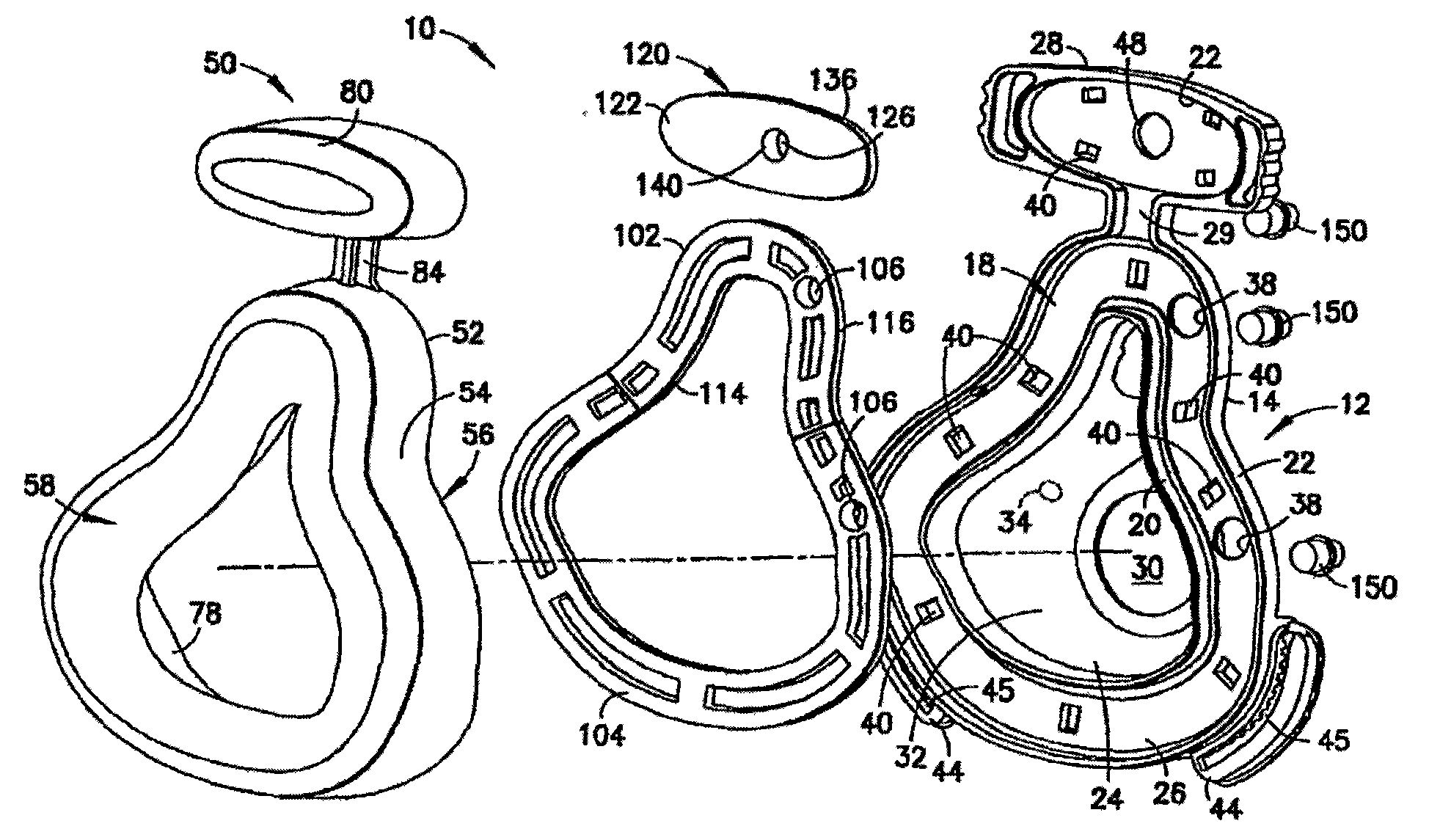
图4为图1中的呼吸面罩分解透视图;Fig. 4 is an exploded perspective view of the breathing mask in Fig. 1;

图5为图1中的呼吸面罩第二分解透视图;Fig. 5 is a second exploded perspective view of the breathing mask in Fig. 1;

图6为形成图1中呼吸面罩膨胀衬垫的囊的后视图;Figure 6 is a rear view of the bladder forming the inflatable cushion of the respiratory mask of Figure 1;

图7为图6所示囊的透视图;Figure 7 is a perspective view of the capsule shown in Figure 6;

图8为沿着图1中线8-8的图1中呼吸面罩的大致横向剖视图;Figure 8 is a general transverse cross-sectional view of the respiratory mask of Figure 1 along line 8-8 in Figure 1;

图9为沿着图1中线9-9的图1中呼吸面罩的大致纵向剖视图;Figure 9 is a general longitudinal sectional view of the respiratory mask of Figure 1 along line 9-9 in Figure 1;

图10为沿着图1中线10-10以及示出了附加特征的图1中呼吸面罩的第二大致横向剖视图;10 is a second general transverse cross-sectional view of the respiratory mask of FIG. 1 taken along line 10-10 of FIG. 1 and showing additional features;

图11为图1中的呼吸面罩另一个实施例的分解透视图;Figure 11 is an exploded perspective view of another embodiment of the respiratory mask of Figure 1;

图12为只示出了面罩囊和保持元件的图11中呼吸面罩的分解透视图;Figure 12 is an exploded perspective view of the respiratory mask of Figure 11 showing only the mask bladder and retaining elements;

图13A为示出了在图1呼吸面罩的基板和保持元件之间的机械固定机构的透视图和局部剖视图;13A is a perspective view and partial cross-sectional view showing a mechanical securing mechanism between the base plate and the retaining element of the respiratory mask of FIG. 1;

图13B为示出了机械机构替代实施例的透视图和局部剖视图;Figure 13B is a perspective view and partial cross-sectional view showing an alternative embodiment of a mechanical mechanism;

图13C为示出了机械固定机构替代实施例的透视图和局部剖视图;Figure 13C is a perspective and partial cross-sectional view showing an alternative embodiment of a mechanical securing mechanism;

图13D为示出了机械固定机构实施例的透视图和局部剖视图;Figure 13D is a perspective and partial cross-sectional view illustrating an embodiment of a mechanical securing mechanism;

图14a为用于呼吸面罩另外实施例的具有固定前额衬垫的膨胀缘边的后视图;Figure 14a is a rear view of an inflatable rim with a fixed forehead pad for another embodiment of a respiratory mask;

图14b为沿着图14a线14b-14b的膨胀缘边的局部剖面透视图。Figure 14b is a partial cutaway perspective view of the expanded rim along line 14b-14b of Figure 14a.

图15为示出了图1中呼吸面罩实施例的分解透视图;Figure 15 is an exploded perspective view showing the embodiment of the respiratory mask of Figure 1;

图16为示出了用于把固定系带固定到面罩上的闭锁的、图1中呼吸面罩一部分的透视图;Figure 16 is a perspective view of a portion of the respiratory mask of Figure 1 showing the latches used to secure the straps to the mask;

图17为图16中闭锁从呼吸面罩上卸下的闭锁分解透视图;Fig. 17 is an exploded perspective view of the latch in Fig. 16 with the latch removed from the breathing mask;

图18为示出了呼吸面罩一部分的透视图,其中呼吸面罩在图16中示出,具有与该呼吸面罩连接的闭锁;Figure 18 is a perspective view showing a portion of the breathing mask shown in Figure 16 with a latch attached to the breathing mask;

图19为根据另一个实施例的闭锁的透视图;Figure 19 is a perspective view of a latch according to another embodiment;

图20为图19中闭锁的纵向剖视图;Figure 20 is a longitudinal sectional view of the latch in Figure 19;

图21为呼吸面罩鼻覆盖实施例的透视图;Figure 21 is a perspective view of an embodiment of a respiratory mask nose cover;

图22为从面罩配戴者接触侧观察的图21中呼吸面罩的透视图;Figure 22 is a perspective view of the respiratory mask of Figure 21 viewed from the mask wearer contact side;

图23为从面罩侧观察的图21中呼吸面罩的透视图;Figure 23 is a perspective view of the respiratory mask of Figure 21 viewed from the mask side;

图24为图21中呼吸面罩保持元件和膨胀/收缩阀的分解透视图;Figure 24 is an exploded perspective view of the respiratory mask retention element and inflation/deflation valve of Figure 21;

图25为图24中膨胀/收缩阀的分解透视图;Figure 25 is an exploded perspective view of the expansion/deflation valve of Figure 24;

图26为从图23中视图相对侧观察的图21中呼吸面罩的分解透视图,其中具有固定的膨胀/收缩阀;Fig. 26 is an exploded perspective view of the respiratory mask of Fig. 21, with a fixed inflation/deflation valve, viewed from the side opposite to the view in Fig. 23;

图27为沿着图22中线27-27的图21中呼吸面罩的大致纵向剖视图;27 is a general longitudinal cross-sectional view of the respiratory mask of FIG. 21 along line 27-27 of FIG. 22;

图28为图21中呼吸面罩侧面和局部剖视图;Figure 28 is a side and partial sectional view of the breathing mask in Figure 21;

图29A为示出了在关闭位置的面罩膨胀/收缩阀的图21中呼吸面罩一部分的剖视图;以及29A is a cross-sectional view of a portion of the respiratory mask of FIG. 21 showing the mask inflation/deflation valve in a closed position; and

图29B为示出了在打开位置的膨胀/收缩阀的图29A中所示呼吸面罩一部分的剖视图。29B is a cross-sectional view of a portion of the respiratory mask shown in FIG. 29A showing the inflation/deflation valve in an open position.

具体实施方式 Detailed ways

为了在下文中描述,如果使用的话,词语“向上”、“向下”、“垂直”、“水平”、“顶部”、“底部”、“向前”、“向后”、“远端”、“近端”、“内”、“外”以及类似方向术语,应为本发明的实施例在附图中的方向。然而,应该理解的是,本发明可假定许多替代变形和实施例,但除了明确说明意思相反以外。还应该理解的是,在附图示出以及在这里描述的特定器械和实施例只不过是发明的典型实施例,其中同样的构件始终用同样的附图标记表示。For purposes of the following description, the words "upward", "downward", "vertical", "horizontal", "top", "bottom", "forward", "backward", "distal", "Proximal", "inner", "outer" and similar directional terms shall refer to the directions of the embodiments of the present invention in the drawings. It should be understood, however, that the invention may assume many alternative variations and embodiments, except where expressly stated to the contrary. It should also be understood that the particular instruments and embodiments shown in the drawings and described herein are merely exemplary embodiments of the invention, wherein like components are designated by like reference numerals throughout.

参见图1-10,图中示出了根据本发明的呼吸面罩10实施例。呼吸面罩10的尺寸和形状大致设计成覆盖佩戴者的口和鼻以覆盖配戴者的气道,而可称为口腔-鼻呼吸面罩。在此说明书中描述的其他实施例只适合作为鼻面罩,尺寸与形状设计成覆盖配戴者的鼻子和配戴者鼻腔气道。另外,如果期望的话,在本发明范围内设置呼吸面罩10,用于只覆盖配戴者口部。呼吸面罩10可用于医学应用场合或者过程中,例如用于把含有麻醉剂或者氧源的气流输送到病人,或者与专门的医疗器械联合,其中该专门医疗器械例如为用于治疗例如睡眠窒息的睡眠障碍的连续正气压(CPAP)器械。通常,呼吸面罩10包括一般刚性支撑件或者基座12以及与基座12联接的膨胀缘边或者衬垫50。一般地,膨胀缘边50通过保持元件100固定到基座12上,其中该保持元件100在膨胀缘边50和基座12之间形成液密密封。Referring to Figures 1-10, an embodiment of a respiratory mask 10 according to the present invention is shown. The respiratory mask 10 is generally sized and shaped to cover the wearer's mouth and nose to cover the wearer's airway and may be referred to as an oral-nasal respiratory mask. Other embodiments described in this specification are suitable only as nasal masks, sized and shaped to cover the wearer's nose and the wearer's nasal airways. Additionally, it is within the scope of the present invention to provide the respiratory mask 10 for covering only the wearer's mouth, if desired. Respiratory mask 10 may be used in a medical application or procedure, such as for delivering a gas stream containing an anesthetic or an oxygen source to a patient, or in conjunction with a specialized medical device, such as for the treatment of sleep apnea such as sleep apnea. Continuous Positive Air Pressure (CPAP) Apparatus for Barriers. In general, respiratory mask 10 includes a generally rigid support or base 12 and an inflatable rim or cushion 50 coupled to base 12 . Generally, the expansion rim 50 is secured to the base 12 by a retaining element 100 that forms a fluid-tight seal between the expansion rim 50 and the base 12 .

基座12提供大致刚性的结构,用于支撑膨胀缘边50。膨胀缘边50一般通过保持元件100用机械方法固定到基座12上,然而也通过其他方式紧固到基座12上,例如通过保持元件100永久结合到基座12上。这种永久结合技术例如包括但不局限于将保持元件100超声波焊接或者化学熔合到基座12上。基座12为大致的刚性结构,但也允许一些弹性弯曲。基座12限定呼吸面罩10的大致口腔-鼻覆盖形状,并适合于与例如软管或者一般管道的外部装置接口,用于把呼吸面罩10与含有麻醉剂的气流供应源、供氧源、CPAP器械以及其他类似应用装置连接。Base 12 provides a generally rigid structure for supporting expansion rim 50 . Expansion rim 50 is typically mechanically secured to base 12 by retaining element 100 , but may also be secured to base 12 by other means, such as being permanently bonded to base 12 by retaining element 100 . Such permanent bonding techniques include, for example but are not limited to, ultrasonic welding or chemical fusing of the retaining element 100 to the base 12 . Base 12 is a generally rigid structure, but allows some elastic flexing. Base 12 defines the general oral-nasal covering shape of respirator 10 and is adapted to interface with external devices such as hose or general tubing for connecting respirator 10 to a gas flow supply containing an anesthetic agent, an oxygen supply, a CPAP apparatus and other similar applications.

基座12一般由基板14形成,其中该基板14为面板形状的整体元件,而该面板的尺寸和形状设计成覆盖配戴者口部和鼻部(例如口腔-鼻腔气道)。基板14具有朝外面或者外侧16,膨胀缘边50紧固其上的内侧18。如在这里详细描述那样,内侧18通常由内外圆周或者周边延伸的凸缘或者缘边20、22形成,其中该凸缘或者缘边20、22从内侧18向外伸出,并作为内外壁以限制膨胀缘边50内外底面面积。The base 12 is generally formed from a base plate 14 which is a unitary member in the shape of a panel sized and shaped to cover the wearer's mouth and nose (eg, oral-nasal airways). The base plate 14 has an outwardly facing or outer side 16, an inner side 18 to which an expansion rim 50 is fastened. As described in detail herein, the inner side 18 is generally formed by inner and outer circumferential or peripherally extending flanges or rims 20, 22, wherein the flanges or rims 20, 22 project outwardly from the inner side 18 and serve as inner and outer walls to The area of the inner and outer bottom surfaces of the expansion rim 50 is limited.

基板14以球状口腔和鼻覆盖部或者区域24形成,在下文中简称为“覆盖部24”。覆盖部24向外伸向基板14外侧16,其尺寸和形状设计成接纳和覆盖至少配戴者的口部和鼻部。基板14进一步由圆周或者周边延伸的固定法兰26形成,其中该固定法兰26从覆盖部24径向地向外设置。膨胀缘边50用于固定或者紧固到基板14内侧18上的固定法兰26上,用这种方式以至在膨胀缘边50和固定法兰26之间提供大致的液密密封。内外缘边20、22大致限定基板14内侧18上的固定法兰26的内外边界上。固定法兰26提供用于膨胀缘边50的特定支撑结构。The base plate 14 is formed with bulbous oral and nasal coverings or regions 24, hereinafter simply referred to as "coverings 24". Covering portion 24 extends outwardly toward outer side 16 of base plate 14 and is sized and shaped to receive and cover at least the mouth and nose of the wearer. The base plate 14 is further formed by a circumferential or peripherally extending fixing flange 26 , wherein the fixing flange 26 is arranged radially outwardly from the cover 24 . The expansion rim 50 is intended to be secured or fastened to the mounting flange 26 on the inner side 18 of the base plate 14 in such a manner as to provide a substantially fluid-tight seal between the expansion rim 50 and the mounting flange 26 . The inner and outer rims 20 , 22 generally define the inner and outer boundaries of the mounting flange 26 on the inner side 18 of the base plate 14 . The fixing flange 26 provides a specific support structure for the expansion rim 50 .

如在前面指出那样,基板14一般为整体元件,并一般具有覆盖部24和例如在塑性模制工艺期间整体形成一起的固定法兰26。然而,如果期望的话,覆盖部24和固定法兰26可以是分开的元件,通过在医学面罩领域中惯用手段结合在一起,以形成基板14。基板14一般由塑性材料形成或者模制,其中该塑性材料例如为聚碳酸酯或者其他类似的刚性或者半刚性塑料,然而可能的话,可以由例如铝或者适当的医学级不锈钢的金属制造。As noted previously, the base plate 14 is generally a unitary member and generally has a cover portion 24 and a securing flange 26 integrally formed together, for example during a plastic molding process. However, if desired, the cover portion 24 and the securing flange 26 may be separate elements joined together by means conventional in the medical mask art to form the base plate 14 . The base plate 14 is generally formed or molded from a plastic material such as polycarbonate or other similar rigid or semi-rigid plastic, but may, where possible, be fabricated from metal such as aluminum or suitable medical grade stainless steel.

基板14选择性地包括从固定法兰26顶端伸出的前额延伸部28。一般地,如图中所示,前额延伸部28作为基板14的一部分整体地形成,然而特别是可作为固定到基板14和固定法兰26的分开结构设置。前额延伸部28适合于支撑膨胀前额衬垫80,方式几乎与固定法兰26支撑膨胀缘边50的主体区域相同。如在这里更进一步描述的那样,膨胀缘边50一般地为具有作为膨胀缘边50一部分形成的前额衬垫80的整体结构或者元件。然而,由于前额衬垫80可容易作为与膨胀缘边50一部分的主体区域分开的结构形成,因此,在此说明书中,不同的附图标记用于标识与前额衬垫80以及由此在基板14上的支撑结构连接的元件。因此,为了此说明书公开的目的,术语“膨胀缘边”通常用于包括前额衬垫80,尽管此元件单独用附图标记“80”表示。The base plate 14 optionally includes a forehead extension 28 projecting from the top end of the mounting flange 26 . Generally, the forehead extension 28 is integrally formed as part of the base plate 14 as shown in the figures, but may in particular be provided as a separate structure secured to the base plate 14 and the securing flange 26 . The forehead extension 28 is adapted to support the inflatable forehead pad 80 in much the same way that the securing flange 26 supports the main body area of the inflatable rim 50 . As described further herein, the inflatable rim 50 is generally a unitary structure or element having the forehead pad 80 formed as part of the inflatable rim 50 . However, since the forehead pad 80 can readily be formed as a separate structure from the main body region that is part of the inflatable rim 50, different reference numerals are used throughout this specification to identify the forehead pad 80 and thus the substrate 14. Elements attached to the supporting structure. Thus, for the purposes of this specification disclosure, the term "expansion rim" is generally used to include forehead pad 80, although this element is individually designated by the reference numeral "80".

同样,前额延伸部28通常被认为是固定法兰26的一部分,尽管前额延伸部28可以是通过例如机械紧固等等的适当方式固定到固定法兰26上的不同结构。前额衬垫80紧固到前额延伸部28上,以在前额衬垫80和前额延伸部28之间提供大致的液密密封,其中连接方式与在膨胀缘边50主体部和固定法兰26之间的连接类似。具体地说,与膨胀缘边50主体部通过保持元件100紧固到固定法兰26上几乎相同方式,前额衬垫80一般地通过前额保持元件120紧固到前额延伸部28上。在这里提供保持元件100和前额保持元件120的细节。Likewise, the forehead extension 28 is generally considered to be part of the securing flange 26, although the forehead extension 28 could be a different structure secured to the securing flange 26 by suitable means such as mechanical fastening or the like. A forehead pad 80 is fastened to the forehead extension 28 to provide a substantially fluid-tight seal between the forehead pad 80 and the forehead extension 28 in the same manner as between the main body portion of the expansion rim 50 and the retaining flange 26. The connections between are similar. Specifically, forehead liner 80 is generally secured to forehead extension 28 via forehead retaining element 120 in much the same manner that the main body portion of inflatable rim 50 is secured to securing flange 26 via retaining element 100 . Details of retention element 100 and forehead retention element 120 are provided herein.

在固定法兰26上的外缘边22也围绕前额延伸部28外周边延伸,以在前额延伸部28上形成外周壁或者缘边,从而在前额衬垫80固定到前额延伸部28上时,限制该前额衬垫80的外底面面积或者部分面积。因此,外缘边22通常连续地围绕基板14的整个外周边。然而,外缘边22形成有敞开连接通道29,其中该通道29在固定法兰26和前额延伸部28之间,如在这里描述那样,作为把膨胀缘边50主体部和前额衬垫80连接起来的连接元件或者结构。The outer rim 22 on the fixing flange 26 also extends around the outer periphery of the forehead extension 28 to form a peripheral wall or rim on the forehead extension 28 so that when the forehead pad 80 is secured to the forehead extension 28, The outer bottom surface area or partial area of the forehead pad 80 is limited. Thus, the outer rim 22 is generally continuous around the entire outer perimeter of the base plate 14 . However, the outer rim 22 is formed with an open connecting passage 29 between the securing flange 26 and the forehead extension 28 as described herein for connecting the main body portion of the inflatable rim 50 to the forehead pad 80. connected elements or structures.

覆盖部24一般地形成有大的中心开口30。该中心开口30可在形成基板14的模制工艺期间形成在覆盖部24,或者可选择的是,可以在基板14模制完成后切成覆盖部24。中心开口30作为用于把呼吸面罩10与其他器械联接的主要接口位置或者配合点来设置。因此,中心开口30可适合于连接到用于供应含有麻醉剂的气流的供应管道上,或者连接到呼吸面罩10的供氧管道上,或者连接到与CPAP器械结合的正气压供应管道上。此外,中心开口30可适合于接收用于从外部装置连接到供应管道上的配件。如参考在这里讨论的图26清楚理解那样,这种配件的实例为90°弯头。Cover portion 24 is generally formed with a large central opening 30 . The central opening 30 may be formed in the cover portion 24 during the molding process to form the base plate 14, or alternatively, may be cut into the cover portion 24 after the base plate 14 has been molded. Central opening 30 is provided as the primary interface location or mating point for coupling respiratory mask 10 to other equipment. Thus, the central opening 30 may be adapted to be connected to a supply line for supplying an anesthetic-containing gas flow, or to an oxygen supply line of the breathing mask 10, or to a positive air pressure supply line in combination with a CPAP machine. Furthermore, the central opening 30 may be adapted to receive a fitting for connection to the supply conduit from an external device. An example of such a fitting is a 90° elbow, as is clearly understood with reference to FIG. 26 discussed herein.

覆盖部24通常在基板14的内侧18限定基本上凹入的内部孔穴或者凹口32,其中的形状设计成与人面部口-鼻形状吻合。凹口32形状通常设计成接纳配戴者鼻子和嘴,其中固定法兰26限定围绕凹口32的外周边。因此,利用膨胀缘边50主体部紧固或者附着于基板14内侧18上的固定法兰26上,膨胀缘边50通常适合于沿着包围鼻梁的连续周边接触与配戴者面部相吻合,其中该周边沿着配戴者面颊延伸并在配戴者下嘴唇延伸。覆盖部24可由一个或多个效用开口34形成,其中该开口用于与可与呼吸面罩10一起使用的其他设备接口。以虚线示出的效用开口34是用于接纳供应管或者类似器械的可选择开口。此外覆盖部24可形成有凸埋式管道36,用于在凹口32和外部设备之间提供流体连通。管道36一般地作为压力获取端口,用于把压力反馈到相关器械或者用于监控目的。The cover portion 24 generally defines a substantially concave interior cavity or indentation 32 on the inner side 18 of the base plate 14, which is shaped to conform to the mouth-nose shape of the human face. The notch 32 is generally shaped to receive a wearer's nose and mouth, with the securing flange 26 defining an outer perimeter around the notch 32 . Thus, with the main body of the expansion rim 50 fastened or otherwise attached to the mounting flange 26 on the inner side 18 of the base plate 14, the expansion rim 50 is generally adapted to conform to the face of the wearer along a continuous perimeter surrounding the bridge of the nose, wherein The perimeter extends along the wearer's cheeks and over the wearer's lower lip. Cover portion 24 may be formed by one or more utility openings 34 for interfacing with other devices that may be used with respiratory mask 10 . The utility opening 34, shown in phantom, is an optional opening for receiving a supply tube or similar instrument. Additionally the cover 24 may be formed with a male buried conduit 36 for providing fluid communication between the recess 32 and external equipment. Conduit 36 generally serves as a pressure acquisition port for pressure feedback to associated instruments or for monitoring purposes.

如显示的那样,固定法兰26围绕覆盖部24在圆周方向延伸,并为膨胀缘边50提供支撑。如在这里描述的那样,在一个实施例中的膨胀缘边50可分成单独的膨胀“腔室”或者“空洞”,其中每个均可分别地充满流体化介质,以使膨胀缘边50膨胀或者填充。结果,对于形成在膨胀缘边50的每个腔室/空洞,固定法兰26一般地限定至少一个膨胀/收缩开口38。膨胀/收缩开口38适合于接纳例如阀门的器械或者结构,其中这种器械或者结构用于允许流体化介质进入到腔室/空洞内以及一般地用于从该腔室/空洞中抽出流体化介质。在下文中,膨胀/收缩开口38将仅被称为“膨胀开口38”,然而很显然,这些开口也可具有收缩或者流体化介质“去除”功能。As shown, the fixing flange 26 extends circumferentially around the cover portion 24 and provides support for the expansion rim 50 . As described herein, the inflatable rim 50 in one embodiment may be divided into individual inflation "chambers" or "voids," each of which may be individually filled with a fluidizing medium to inflate the inflatable rim 50 Or fill. As a result, the fixed flange 26 generally defines at least one expansion/contraction opening 38 for each cavity/void formed in the expansion rim 50 . The inflation/deflation opening 38 is adapted to receive a device or structure, such as a valve, for allowing the fluidizing medium to enter the chamber/cavity and generally for withdrawing the fluidizing medium from the chamber/cavity . In the following, the inflation/deflation openings 38 will only be referred to as "inflation openings 38", however it is clear that these openings may also have a deflation or fluidization medium "removal" function.

另外,固定法兰26一般地限定一个或多个舌片接纳口40,用于接纳机械舌片,如在这里论述的那样,这些舌片与保持缘边100结合,而其中保持缘边100用于把膨胀缘边50紧固到基板14上,特别是固定法兰26上。如在这里描述那样,保持元件100一般地包括多个机械固定舌片,这些舌片适合于啮合舌片开口40,以把在压缩状态的膨胀缘边50的至少一部分紧固在保持元件100和固定法兰26之间。然而,可以预见的是,如前面指出的那样,在保持元件100和固定法兰26之间的机械啮合可使用永久的固定结合技术。舌片开口40一般地包括在基板14外侧16上的升高的舌片缘边42,该缘边围绕并保护机械舌片。若干舌片开口40也限定在前额延伸部18,用于与前额保持元件120结合来接纳机械舌片。如在这里论述那样,前额保持元件120包括大致与在保持元件100上的那些类似的机械舌片结构。如在这里描述那样,这些机械舌片结构在前额延伸部28上舌片开口40中的啮合用来以大致液密方式把前额衬垫80紧固到前额延伸部28上。如在这里充分地详细描述那样,基板14外侧16以及相应地前额延伸部28外侧一般地限定大致椭圆形的升高凸缘或者缘边43,该凸缘或者缘边43形成用于通过与前额保持元件120结合的机械舌片啮合的缘边或者凸缘结构。In addition, the retaining flange 26 generally defines one or more tongue-receiving openings 40 for receiving mechanical tongues that, as discussed herein, engage the retaining rim 100 with the retaining rim 100 For fastening the expansion rim 50 to the base plate 14 , in particular to the fixing flange 26 . As described herein, the retaining element 100 generally includes a plurality of mechanical securing tabs adapted to engage the tab openings 40 to secure at least a portion of the expanded rim 50 in the compressed state between the retaining element 100 and the retaining element 100. Between the fixed flanges 26. However, it is contemplated that, as previously indicated, the mechanical engagement between the retaining member 100 and the fixed flange 26 may utilize a permanent fixed bonding technique. The tongue opening 40 generally includes a raised tongue rim 42 on the outer side 16 of the base plate 14 that surrounds and protects the mechanical tongue. A number of tongue openings 40 are also defined in the forehead extension 18 for receiving mechanical tongues in conjunction with the forehead retaining element 120 . As discussed herein, forehead retaining element 120 includes mechanical tongue structures substantially similar to those on retaining element 100 . As described herein, the engagement of these mechanical tab structures in the tab openings 40 on the forehead extension 28 serves to secure the forehead pad 80 to the forehead extension 28 in a substantially fluid-tight manner. As fully described herein, the outer side 16 of the base plate 14 and correspondingly the outer side of the forehead extension 28 generally define a generally elliptical raised flange or rim 43 formed for passage with the forehead retaining member. 120 bonded mechanical tongues engage the rim or flange structure.

基板14以及更具体地说固定法兰26,一般包括固定结构,用于把固定系带(未示出)紧固到呼吸面罩10上。这种系带用来把呼吸面罩10紧固到配戴者的面部上。一般地,系带围绕配戴者头部延伸并例如通过钩-环紧固件相连。可选择的是,其中端部紧固到基板14相对侧的单个弹性系带可用来把呼吸面罩10紧固到配戴者面部上。在基板14上的系带固定结构包括一对布置在基板14相对下侧并从该基板14外侧16向外延伸的导轨44。导轨44一般地形成为在基板14外侧16上固定法兰26的一部分。导轨44大致为弧形结构,其中该弧形结构一般地例如在模制工艺期间整体形成为基板14的一部分。导轨44用来支撑相应的闭锁160,其中该闭锁160适合于接纳和支撑相应的紧固系带或者单个紧固系带的相对两端。导轨44一般地形成有细长和弧形的调节槽45(在图16中示出),其中该槽包括布置在其相对侧的多个啮合槽46,用于接纳在闭锁160上的突出结构,其中该突出结构用于把闭锁160紧固在导轨44上的固定然而可释放的位置上。啮合槽46限定在多个接触元件47之间,其中每个接触元件47均具有朝向调节槽45的锥形或者弧形(例如拱形)的表面S。导轨44通常沿着基板14下侧布置,以便与闭锁160结合的系带可沿着配戴者左右下颊区域围绕配戴者头部延伸。The base plate 14 , and more specifically the securing flange 26 , generally includes securing structure for securing a securing strap (not shown) to the respiratory mask 10 . Such straps are used to secure the respirator 10 to the wearer's face. Typically, the straps extend around the wearer's head and are attached, for example, by hook-and-loop fasteners. Alternatively, a single elastic strap with ends secured to opposite sides of base plate 14 may be used to secure respiratory mask 10 to the wearer's face. The strap attachment structure on the base plate 14 includes a pair of rails 44 disposed on opposite undersides of the base plate 14 and extending outwardly from the outer side 16 of the base plate 14 . The rail 44 is generally formed as part of securing the flange 26 on the outer side 16 of the base plate 14 . The rails 44 are generally arcuate structures, wherein the arcuate structures are typically integrally formed as part of the base plate 14, for example during a molding process. Rail 44 serves to support a respective latch 160 adapted to receive and support opposite ends of a respective fastening strap or a single fastening strap. The guide rail 44 is generally formed with an elongated and arcuate adjustment slot 45 (shown in FIG. , wherein the protruding structure is used to fasten the latch 160 on the guide rail 44 in a fixed but releasable position. The engaging groove 46 is defined between a plurality of contact elements 47 , wherein each contact element 47 has a tapered or arcuate (eg arched) surface S facing the adjustment groove 45 . Rails 44 are generally disposed along the underside of base plate 14 so that straps incorporating latches 160 may extend around the wearer's head along the wearer's left and right lower cheek regions.

最后,前额延伸部28包括大致与前面描述的膨胀开口38相同的分开的膨胀/收缩开口48。如在这里描述那样,膨胀/收缩开口48适合于支撑用于使与前额衬垫80结合的膨胀“腔室”或者“空洞”膨胀的阀门或者类似结构。膨胀开口48也将具有收缩或者流体化介质“去除”功能,并在这里也称为“膨胀开口48”以与前面描述的“膨胀开口38”一致。Finally, the forehead extension 28 includes a separate inflation/deflation opening 48 substantially identical to the inflation opening 38 described previously. Inflation/deflation opening 48 is adapted to support a valve or similar structure for inflating an inflation "chamber" or "void" associated with forehead pad 80, as described herein. The inflation opening 48 will also have a constriction or fluidization medium "removal" function and is also referred to herein as the "expansion opening 48" to be consistent with the previously described "inflation opening 38".

通常,膨胀缘边50紧固或者附着到基座12上,从而在膨胀缘边50和基座12之间,更具体地说在膨胀缘边50和基板14的固定法兰26之间形成液密密封。膨胀缘边50通常包括整体的、囊状结构或者元件52,为了方便起见,在下文中简称为“囊52”,这种结构或者元件形成了膨胀缘边50的主体部54和前额衬垫80两个部分。如前面指出那样,术语“膨胀缘边”是用来包围主体部54和前额衬垫80二者,其中该主体部54适合于通过保持元件100连接到固定法兰26上,而前额衬垫80适合于通过前额保持元件120连接到前额延伸部28上。囊52一般地在注塑模具中由这样一种材料注塑形成,其中该材料在固化时具有弹性特征,从而当流体化介质引入到囊52中时该囊52可膨胀。当形成时,囊52是通过薄膜材料形成或者限定的整体结构或者主体。用于注射模制囊52的适当材料实例包括硅树脂、热塑合成橡胶、聚氨酯、硫化橡胶及其他类似的材料。Typically, the expansion rim 50 is fastened or attached to the base 12 such that a liquid fluid is formed between the expansion rim 50 and the base 12 , and more specifically between the expansion rim 50 and the mounting flange 26 of the base plate 14 . Tight seal. The inflatable rim 50 generally includes a unitary, bladder-like structure or member 52, hereinafter referred to simply as "the bladder 52" for convenience, that forms both the main body portion 54 of the inflatable rim 50 and the forehead pad 80. parts. As previously pointed out, the term "expansion rim" is used to surround both the main body portion 54 and the forehead pad 80, wherein the main body portion 54 is adapted to be connected to the fixing flange 26 by the retaining element 100, and the forehead pad 80 Adapted to be attached to the forehead extension 28 via the forehead retaining element 120 . The bladder 52 is typically injection molded in an injection mold from a material that, when cured, has elastic characteristics such that the bladder 52 is expandable when a fluidizing medium is introduced into the bladder 52 . When formed, bladder 52 is a unitary structure or body formed or defined by a thin film material. Examples of suitable materials for injection molding bladder 52 include silicone, thermoplastic elastomer, polyurethane, vulcanized rubber, and other similar materials.

囊52通常形成有啮合侧56和衬垫侧58,其中该啮合侧56用于与保持元件100和前额保持元件120结合,而衬垫侧58朝向外部,并且是囊52形成与配戴者面部接触的接触面的侧部。穿过主体部54区段的横截面和通过囊52前额衬垫80区段的类似截面展现主体部54和前额衬垫80每个均为大致的U形横截面。主体部54的U形横截面通常由具有适合于与保持元件100啮合的结构的基部或者区域60、形成囊52衬垫侧58较大表面积的衬垫部或者区域62限定。基部60大致形成主体部54的U形横截面的底部三分之一到底部二分之一。基部60一般地形成两个向内伸出和大致为U形的法兰64。法兰64每个均包括向上的延伸部或者直立的凸缘或者缘边66,这限定了与在这里描述的保持元件100上对应的凸缘结构啮合的槽68。The bladder 52 is generally formed with an engaging side 56 for engaging the retaining element 100 and the forehead retaining element 120, and a padded side 58, which faces outwardly and is formed with the bladder 52 in contact with the wearer's face. The side of the contact surface that is in contact. A cross-section through a section of body portion 54 and a similar section through a section of forehead pad 80 of bladder 52 reveal that body portion 54 and forehead pad 80 are each generally U-shaped in cross-section. The U-shaped cross-section of body portion 54 is generally defined by a base portion or region 60 having a structure adapted to engage retaining element 100 , a pad portion or region 62 forming a larger surface area on padded side 58 of bladder 52 . The base portion 60 generally forms the bottom third to the bottom half of the U-shaped cross-section of the main body portion 54 . The base 60 is generally formed with two inwardly projecting and generally U-shaped flanges 64 . Flanges 64 each include an upward extension or upstanding flange or rim 66 that defines a slot 68 that engages a corresponding flange structure on retaining element 100 as described herein.

从图中看到的囊52各种横截面图可以理解,主体部54和前额衬垫80的U形横截面形式呈现不均匀的壁厚。主体部54的基部60具有的厚度比衬垫部62大。由于囊52由薄膜材料形成整体元件,则在基部60和衬垫部62之间没有特定的分界线。然而,如建议的那样,基部60可认为是形成主体部54的大约三分之一到二分之一U形横截面。形成囊52薄膜的壁厚大致从基部60逐渐减少或者变狭窄,以形成主体部54的衬垫部62。此壁厚的逐渐减少过渡区在图中以附图标记70表示。As can be appreciated from the various cross-sectional views of bladder 52 seen in the figures, the U-shaped cross-sectional form of body portion 54 and forehead pad 80 exhibits uneven wall thickness. The base portion 60 of the main body portion 54 has a greater thickness than the pad portion 62 . Since bladder 52 is formed as a unitary member from a thin film material, there is no specific dividing line between base portion 60 and pad portion 62 . However, as suggested, the base portion 60 may be considered to form approximately one-third to one-half of a U-shaped cross-section of the main body portion 54 . The wall thickness of the membrane forming bladder 52 generally tapers or narrows from base portion 60 to form pad portion 62 of body portion 54 . This transition zone of tapered wall thickness is denoted by reference numeral 70 in the figure.

囊52的不均匀壁厚具有几个优点。囊52的不均匀壁厚允许主体部54的基部60和衬垫部62以不同比率展开,以当流体化介质被引入膨胀缘边50时,控制膨胀缘边50的膨胀。更具体地说,囊52的变化的、不均匀的壁厚控制膨胀缘边50扩展的量和方向,其中当流体化介质被引入膨胀缘边50时,在衬垫部62出现更大扩展,而在囊52主体部54的基部60出现较少扩展。这允许膨胀缘边50衬垫侧58比啮合侧56扩展更多,而衬垫侧58将容易与配戴者面部形状吻合。通常,囊52的可变膨胀特征能够使膨胀缘边50扩展并与配戴者面部吻合,以形成有效密封。由此,囊52的可变膨胀特征提高了呼吸面罩10与配戴者皮肤的密封,并提高了在配戴者鼻子和嘴周围呼吸面罩10的密封特性。The non-uniform wall thickness of bladder 52 has several advantages. The non-uniform wall thickness of bladder 52 allows base portion 60 and cushion portion 62 of body portion 54 to expand at different rates to control expansion of inflation rim 50 when a fluidizing medium is introduced into inflation rim 50 . More specifically, the varying, non-uniform wall thickness of bladder 52 controls the amount and direction of expansion of inflatable rim 50, wherein greater expansion occurs at cushion portion 62 when a fluidizing medium is introduced into inflatable rim 50, Less expansion occurs at the base 60 of the body portion 54 of the bladder 52 . This allows the padded side 58 of the expansion rim 50 to expand more than the engaging side 56, and the padded side 58 will readily conform to the shape of the wearer's face. Generally, the variable inflation feature of bladder 52 enables inflation rim 50 to expand and conform to the wearer's face to form an effective seal. Thus, the variable inflation feature of bladder 52 improves the seal of respirator 10 against the wearer's skin and improves the seal characteristics of respirator 10 around the wearer's nose and mouth.

此外,囊52可在主体部54包括内壁或者分隔件72,从而囊52在主体部54中在多个内部分隔件72之间限定多个内部空洞72。内部分隔件72把囊52分离或者分隔成若干单独部分,这些部分可分别充满流体化介质。该分隔件允许不同的流体化介质用在不同部分中。例如,有益的是,在一个部分中提供更有弹性的区域,而在另一个部分中提供更柔性的区域。这可通过改变在每个部分中压力或者通过利用具有不同机械性能的流体化介质来实现。做为选择,内部分隔件72可包括压力平衡结构76,例如小孔或者孔眼或者节流阀,用于在内部空洞或者部分74之间提供流体连通。当流体化介质被引入囊52时,这种压力平衡结构76还允许流体化介质从一个内部空洞74穿过下一个内部空洞74。因此当压力平衡结构76省略时,相应的内部空洞74将彼此隔离,同时囊52与保持元件100结合,而保持元件100固定到固定法兰26上,此时,如果期望的话,各种“封闭”的内部空洞74可加压到不同高度。Additionally, the bladder 52 may include interior walls or dividers 72 in the body portion 54 such that the bladder 52 defines a plurality of interior cavities 72 in the body portion 54 between the plurality of interior dividers 72 . The internal partition 72 separates or divides the bladder 52 into separate parts, which can be filled with a fluidizing medium, respectively. This divider allows different fluidization media to be used in different sections. For example, it may be beneficial to provide a more elastic region in one part and a more flexible region in the other part. This can be achieved by varying the pressure in each section or by using fluidization media with different mechanical properties. Alternatively, the internal partition 72 may include a pressure equalizing structure 76 , such as a small hole or orifice or a restriction, for providing fluid communication between the internal voids or portions 74 . This pressure equalization structure 76 also allows fluidization medium to pass from one interior cavity 74 to the next as the fluidization medium is introduced into the bladder 52 . Thus when the pressure equalization structure 76 is omitted, the corresponding internal cavities 74 will be isolated from each other while the bladder 52 is engaged with the retaining element 100 which is secured to the fixed flange 26, at which point, if desired, various "closed" The internal cavity 74 of " can be pressurized to different heights.

此外,囊52一般地包括密封翼片78,其中在囊52注射模制工艺期间,该翼片78一般地作为主体部54的一部分整体地形成。密封翼片78通常为薄膜材料形式,其中该薄膜从衬垫部62朝向由基板14覆盖部24限定的凹口32伸出。密封翼片78一般地围绕囊52主体部54上衬垫部62而周向延伸,并一般地围绕配戴者鼻梁,沿着鼻子的侧面,并围绕配戴者嘴部接触配戴者皮肤,用于提高呼吸面罩10的密封特性。密封翼片78为设置在囊52上的可选择结构。Additionally, the bladder 52 generally includes a sealing flap 78 that is generally integrally formed as part of the main body portion 54 during the injection molding process of the bladder 52 . The sealing flap 78 is generally in the form of a thin film material that protrudes from the pad portion 62 toward the recess 32 defined by the cover portion 24 of the substrate 14 . The sealing flap 78 extends generally circumferentially around the upper cushion portion 62 of the main body portion 54 of the bladder 52 and generally around the bridge of the wearer's nose, along the sides of the nose, and around the wearer's mouth in contact with the wearer's skin, For improving the sealing properties of the breathing mask 10 . Sealing flap 78 is an optional feature provided on bladder 52 .

如前面指出那样,前额延伸部28、前额衬垫80和前额保持元件120一般地为呼吸面罩10的可选择的部件。这些部件主要用于提高呼吸面罩10配戴者的舒适程度,因此可省略。如前面指出那样,这些部件可容易地以单独结构设置,其中前额延伸部28固定或者连接到固定法兰26上,而独立的前额衬垫80此后通过前额保持元件120紧固或者固定到前额延伸部上。因此,如前面指出那样,由于这些元件可容易地分别以与囊52的主体部54和固定法兰26分开的结构设置,因此在本说明书中,前额延伸部28和前额衬垫80的特征用不同附图标记表示。As noted previously, forehead extension 28 , forehead pad 80 and forehead retaining element 120 are generally optional components of respiratory mask 10 . These components are mainly used to improve the comfort level of the wearer of the respiratory mask 10, so they can be omitted. As previously indicated, these components can easily be provided in a separate structure, wherein the forehead extension 28 is fixed or connected to the fixing flange 26, and the separate forehead pad 80 is thereafter fastened or fixed to the forehead extension by means of the forehead retaining element 120. department. Therefore, as previously indicated, the features of the forehead extension 28 and the forehead pad 80 are used in this description because these elements can easily be provided in separate structures from the main body portion 54 of the bladder 52 and the securing flange 26, respectively. Different reference signs indicate.

前额衬垫80限定与囊52主体部54不同和分开的前额内部空洞82。前额内部空洞82在结构上大致与前面描述的内部空洞或者部分74类似,然而形状与从基板14的固定法兰26伸出的前额延伸部28的大致椭圆形状匹配。前额衬垫80一般地通过薄的非膨胀连接元件84连接到囊52主体部54上。前额衬垫80包括用于啮合前额保持元件120的类似的啮合结构,例如设置在主体部54上,以与保持元件100啮合。具体地说,这种啮合结构通常类似于设置在主体部54的基部60上的结构。由此前额衬垫80一般地包括前额基部88和前额衬垫部或者区域90,而该前额基部88和前额衬垫部或者区域90大致与在前面描述的主体部54上的基部60和衬垫部62类似。此外,前额基部88形成前额衬垫80U形横截面的底部三分之一到底部二分之一。然而,前额基部88包括单个、向内伸出、圆周方向延伸以及大致为U形的法兰92。法兰92包括向上延伸或者直立的凸缘或者缘边94,这限定了用于与在如这里描述的前额保持元件120上的对应凸缘结构啮合的槽96。The forehead pad 80 defines an interior forehead void 82 distinct and separate from the main body portion 54 of the bladder 52 . The forehead interior void 82 is generally similar in structure to the previously described interior void or portion 74 , yet is shaped to match the generally oval shape of the forehead extension 28 protruding from the attachment flange 26 of the base plate 14 . The forehead pad 80 is generally attached to the main body portion 54 of the bladder 52 by a thin, non-inflatable attachment member 84 . The forehead pad 80 includes similar engagement structure for engaging the forehead retaining element 120 , for example provided on the main body portion 54 , to engage with the retaining element 100 . Specifically, such engagement structures are generally similar to those provided on the base portion 60 of the main body portion 54 . The forehead pad 80 thus generally includes a forehead base 88 and a forehead pad or region 90 that are substantially the same as the base 60 and pad on the body portion 54 previously described. Section 62 is similar. Additionally, forehead base 88 forms the bottom third to bottom half of the U-shaped cross-section of forehead pad 80 . However, the forehead base 88 includes a single, inwardly projecting, circumferentially extending, and generally U-shaped flange 92 . Flange 92 includes an upwardly extending or upstanding flange or rim 94 that defines a slot 96 for engaging a corresponding flange structure on forehead retaining element 120 as described herein.

如前面指出的那样,前额衬垫80包括与主体部54类似的U形横截面,并还呈现与前额基部88和前额衬垫部90关联的类似的不均匀壁厚。如前面描述的基部60和衬垫部62那样,前额基部88具有比前额衬垫部90大的壁厚。前额基部88的壁厚逐渐减小或者变窄,以形成前额衬垫部90,其中前额基部88和前额衬垫部90通过逐渐减少或者变狭壁厚过渡区98连接。由此,前额衬垫80将具有与前面针对囊52主体部54详细描述的那样类似的膨胀性能。As previously noted, forehead pad 80 includes a similar U-shaped cross-section as body portion 54 and also exhibits a similar uneven wall thickness associated with forehead base portion 88 and forehead pad portion 90 . As with base 60 and pad 62 previously described, forehead base 88 has a greater wall thickness than forehead pad 90 . The forehead base 88 tapers or narrows in wall thickness to form a forehead pad 90 , wherein the forehead base 88 and forehead pad 90 are connected by a tapered or narrowed wall thickness transition 98 . Thus, the forehead pad 80 will have similar expansion properties as previously described in detail for the main body portion 54 of the bladder 52 .

在呼吸面罩10的目前实施例中,示出的保持元件100为多件结构,特别是,为两件结构。保持元件100一般地分为几部分以对应于形成在囊52中内部空洞74的数目。保持元件100通常包括第一保持元件102和第二保持元件104,以与在图1-10中所示囊52中的内部分隔件72限定的两个内部空洞74相对应。囊52可还以另外的内部分隔件72分成几部分,而如需要的话,保持元件100可进一步分隔,以与形成在囊52中另外的内部空洞74数目对应。每个第一和第二保持元件102、104均具有膨胀/收缩开口106,该开口大致与在基板14的固定法兰26上膨胀开口38重合。对应或者重合的膨胀开口38、106一般地适合于可配合地支撑如在这里描述的膨胀/收缩阀。膨胀/收缩开口106在这里还称为“膨胀开口106”以与结合膨胀开口38使用的术语一致。In the present embodiment of the respiratory mask 10, the illustrated retaining element 100 is a multi-piece construction, in particular, a two-piece construction. The retaining element 100 is generally divided into sections to correspond to the number of internal cavities 74 formed in the bladder 52 . The retaining element 100 generally includes a first retaining element 102 and a second retaining element 104 to correspond with the two interior cavities 74 defined by the interior divider 72 in the bladder 52 shown in FIGS. 1-10 . The bladder 52 can also be divided into sections with further internal partitions 72 , and the retaining element 100 can be further divided, if desired, to correspond to the number of further internal cavities 74 formed in the bladder 52 . Each first and second retaining element 102 , 104 has an expansion/contraction opening 106 which approximately coincides with the expansion opening 38 on the fixing flange 26 of the base plate 14 . Corresponding or coincident inflation openings 38, 106 are generally adapted to cooperatively support an inflation/deflation valve as described herein. The inflation/deflation opening 106 is also referred to herein as “the inflation opening 106 ” to be consistent with the terminology used in connection with the inflation opening 38 .

每个第一和第二保持元件102、104还包括从其底侧伸出的多个固定舌片108,这些舌片适合于与在基板14的固定法兰26中对应的舌片开口40啮合,以把第一和第二保持元件102、104紧固到固定法兰26上。固定舌片108可以是任何适当形状,然而作为固定舌片108的所希望的实施例,描述为大致箭头形状舌片。每个固定舌片108均由一对叉形元件110形成,而其中叉形元件110每个均具有半箭头形状头部112。在使用中,当固定舌片108插入舌片开口40,然后向外弹性弯曲以与围绕相应舌片开口40延伸的升高缘边42啮合时,叉形元件110适合于朝向彼此弯曲。当叉形元件110向外弹性弯曲时,叉形元件头部112将与围绕相应舌片开口40的升高缘边42啮合并此后阻止固定舌片108从舌片开口40去除。Each first and second retaining element 102 , 104 also includes a plurality of securing tongues 108 projecting from its bottom side, adapted to engage corresponding tongue openings 40 in the securing flange 26 of the base plate 14 , to fasten the first and second retaining elements 102 , 104 to the fixing flange 26 . The retaining tab 108 may be of any suitable shape, however as a preferred embodiment of the retaining tab 108 is described as a generally arrowhead shaped tab. Each retaining tongue 108 is formed by a pair of fork-shaped elements 110 each having a half-arrowhead-shaped head 112 . In use, the fork elements 110 are adapted to bend towards each other when the retaining tongues 108 are inserted into the tongue openings 40 and then elastically flexed outwardly to engage the raised rim 42 extending around the respective tongue opening 40 . When the fork elements 110 are elastically bent outwardly, the fork element heads 112 will engage the raised rim 42 surrounding the respective tongue opening 40 and thereafter prevent removal of the securing tongue 108 from the tongue opening 40 .

简要地参考图13A和13B,图中示出了在保持元件100上固定舌片108和在基板14固定法兰26的舌片开口40之间啮合的若干改型。如图13A和13B示出那样,围绕每个舌片开口40的升高缘边42可从舌片开口40周边向外隔开。当连接时,在叉形元件110上半个箭头形状叉形元件头部112可只与舌片开口40周边而不是升高缘边42啮合。在此结构中,升高缘边42作为围绕叉形元件头部112与舌片开口40周边啮合部位的防护屏障,由此阻止损坏此啮合。如果期望的话,每个升高缘边42形成有中心十字元件113。当叉形元件头部112与舌片开口40周边啮合时,十字元件113基本上定位在叉形元件110的头部112之间。因此,一旦固定舌片108贯穿舌片开口40插入,同时叉形元件头部112与舌片开口40周边啮合,则十字元件113阻止叉形元件头部112朝向彼此偏离或者弯曲,由此阻止固定舌片108从舌片开口40移去。十字元件113阻止另外的结构,即一旦啮合建立,该结构阻止对在叉形元件头部112和舌片开口40周边之间啮合进行破坏。Referring briefly to FIGS. 13A and 13B , there are shown several modifications of the engagement between the securing tab 108 on the retaining member 100 and the tab opening 40 in the securing flange 26 of the base plate 14 . As shown in FIGS. 13A and 13B , the raised rim 42 surrounding each tab opening 40 may be spaced outwardly from the perimeter of the tab opening 40 . When connected, the arrowhead-shaped fork member head 112 on the fork member 110 may only engage the tongue opening 40 perimeter and not the raised rim 42 . In this configuration, the raised rim 42 acts as a protective barrier around the location where the fork member head 112 engages the perimeter of the tongue opening 40, thereby preventing damage to this engagement. Each raised rim 42 is formed with a central cross member 113, if desired. The cross member 113 is positioned substantially between the heads 112 of the fork members 110 when the fork member heads 112 are engaged with the perimeter of the tongue opening 40 . Thus, once the securing tongue 108 is inserted through the tongue opening 40 while the fork element heads 112 engage the perimeter of the tongue opening 40, the cross element 113 prevents the fork element heads 112 from deflecting or bending towards each other, thereby preventing the securing. The tongue 108 is removed from the tongue opening 40 . The cross member 113 prevents additional structure that prevents disruption of the engagement between the fork member head 112 and the perimeter of the tongue opening 40 once the engagement is established.

再次参考图1-10,每个第一和第二保持元件102、104还沿着其内外边缘限定圆周内外凸缘或者缘边114、116。内外凸缘114、116是用来与槽68对齐或者配合,其中槽68由形成在囊52主体部54基部60上的相对法兰64上的直立凸缘66限定。每个圆周内外凸缘114、116均具有槽118,其中该槽118用于接纳形成在囊52的主体部54的基部60上的相对法兰64上的各凸缘66。固定舌片108与围绕舌片开口40延伸的圆周升高缘边42的啮合,导致压缩力施加在形成在囊52主体部54基部60上的相对法兰64上,以在囊52主体部54和固定法兰26之间建立大致的液密密封。在这里,相对于组装呼吸面罩10的装配工艺,提供了如下补充详细内容:在固定舌片108和舌片开口40之间对齐啮合,通过在相对的法兰64上保持元件100随后施加的压缩力。保持元件100以及更具体地说第一和第二保持元件102、104可由例如聚碳酸酯的刚塑性材料形成。与基板14情况一样,保持元件100也可由其他适当的材料形成,例如铝或者不锈钢以及适合于用在医疗器械中各等级材料。Referring again to FIGS. 1-10 , each first and second retention member 102 , 104 also defines a circumferential inner and outer flange or rim 114 , 116 along its inner and outer edges. The inner and outer flanges 114 , 116 are intended to align or mate with the slot 68 defined by the upstanding flange 66 formed on the opposing flange 64 on the base 60 of the body portion 54 of the bladder 52 . Each circumferential inner and outer flange 114 , 116 has a slot 118 for receiving each flange 66 formed on the opposing flange 64 formed on the base 60 of the main body portion 54 of the bladder 52 . Engagement of the retaining tab 108 with the circumferential raised rim 42 extending around the tab opening 40 causes a compressive force to be exerted on the opposing flange 64 formed on the base 60 of the main body portion 54 of the bladder 52 to compress against the main body portion 54 of the bladder 52. A substantially liquid-tight seal is established with the fixed flange 26. Here, with respect to the assembly process of assembling the respirator 10, additional details are provided as follows: alignment engagement between the securing tab 108 and the tab opening 40, by the subsequent compression of the retaining element 100 on the opposing flange 64 force. The retaining element 100, and more particularly the first and second retaining elements 102, 104, may be formed from a rigid plastic material such as polycarbonate. As with the base plate 14, the retaining element 100 may also be formed from other suitable materials, such as aluminum or stainless steel and grades of materials suitable for use in medical devices.

如在图4和5清楚示出以及如前面指出的那样,前额保持元件120一般地以分开的固定结构设置,并特别地设计以把前额衬垫80固定到从基板14固定法兰26伸出的前额延伸部28上。前额保持元件120通常适合于与前额延伸部28啮合,并在囊52前额衬垫80前额基部88上形成的向内突出或者延伸法兰92上提供压缩力,以便在前额衬垫80和前额延伸部28之间建立大致的液密密封。前额保持元件120通常包括板状主体122,其中该主体122一般地具有膨胀/收缩开口126,该开口大致定位成与在前额延伸部28中单个膨胀开口48重合。重合的膨胀开口48、126通常支撑膨胀/收缩阀,方式基本上与在固定法兰26中膨胀开口38与在包括保持元件100的第一和第二保持元件102、104中膨胀开口106之间的重合关系相同。膨胀/收缩开口126在这里简称为用于一致性的膨胀开口126。As clearly shown in FIGS. 4 and 5 and as previously indicated, the forehead retaining member 120 is generally provided in a separate securing structure, and is specifically designed to secure the forehead pad 80 to extend from the base plate 14 securing flange 26. on the forehead extension 28 of the The forehead retaining element 120 is generally adapted to engage the forehead extension 28 and provide a compressive force on the inwardly projecting or extending flange 92 formed on the forehead base 88 of the forehead pad 80 of the bladder 52 to provide a compressive force between the forehead pad 80 and the forehead extension. A substantially fluid-tight seal is established between portions 28. The forehead retaining element 120 generally includes a plate-like body 122 , wherein the body 122 generally has an inflation/deflation opening 126 positioned generally to coincide with the single inflation opening 48 in the forehead extension 28 . The coincident expansion openings 48 , 126 generally support the expansion/deflation valve in substantially the same manner as between the expansion opening 38 in the fixed flange 26 and the expansion opening 106 in the first and second retaining elements 102 , 104 comprising the retaining element 100 . The overlapping relationship is the same. The inflation/deflation opening 126 is referred to herein simply as the inflation opening 126 for consistency.

与前面描述的保持元件100一样,前额保持元件120包括从其底侧伸出的多个固定舌片128,其中该固定舌片128适合于与在从基板14固定法兰26伸出的前额延伸部28上的舌片开口40啮合,以把前额保持元件120紧固到前额延伸部28上。固定舌片128可以是任何适当形式,然而描述为由具有半个箭头形状头部132的单个叉形元件130形成,而不是前面描述的固定舌片108的两个叉形元件结构。固定舌片128的叉形元件130以与前面描述的固定舌片108的叉形元件110大致类似方式操作,并当固定舌片128插入在前额延伸部28中舌片开口40中时弯曲,然后弹性弯曲基本上返回到它们的原始的取向。如叉形元件130弹性弯曲基本上返回到其原始的取向时,叉形元件头部132与从基板14外侧16突出的升高凸缘或者缘边43交叠和啮合,并因此与前额延伸部28外侧交叠和啮合,以紧固前额保持元件120成与前额延伸部28啮合。叉形元件130头部132与升高缘边43的啮合此后阻止固定舌片128从前额延伸部28中舌片开口40上移去。Like the retaining element 100 previously described, the forehead retaining element 120 includes a plurality of retaining tongues 128 protruding from its bottom side, wherein the retaining tongues 128 are adapted to extend on the forehead extending from the retaining flange 26 of the base plate 14. The tongue opening 40 on the forehead extension 28 engages to secure the forehead retaining element 120 to the forehead extension 28 . The retaining tongue 128 may be of any suitable form, but is depicted as being formed from a single fork member 130 having half an arrowhead shaped head 132 rather than the two fork member construction of the retaining tongue 108 previously described. The fork element 130 of the fixed tongue 128 operates in a substantially similar manner to the fork element 110 of the previously described fixed tongue 108 and bends when the fixed tongue 128 is inserted in the tongue opening 40 in the forehead extension 28 and then Elastic bends return substantially to their original orientation. When the fork-shaped member 130 elastically bends back substantially to its original orientation, the fork-shaped member head 132 overlaps and engages the raised flange or rim 43 protruding from the outer side 16 of the base plate 14, and thus engages the outer side of the forehead extension 28. Overlap and engage to secure forehead retaining element 120 into engagement with forehead extension 28 . Engagement of the head 132 of the fork member 130 with the raised rim 43 thereafter prevents removal of the securing tongue 128 from the tongue opening 40 in the forehead extension 28 .

前额保持元件120还包括两个间距小的内外凸缘或者缘边134、136,其中外凸缘136一般地沿着前额保持元件120的外周边形成。固定舌片128一般从内凸缘134伸出,而内凸缘134在长度上略微长,以从前额保持元件120比外凸缘136向外突出更大距离。一般地,当前额保持元件120连接到前额延伸部28内侧时,内凸缘134是用来与那里接触的。圆周外凸缘136是用来与槽96对齐的,其中槽96由形成在囊52的前额衬垫80的前额基部88上的向内延伸法兰92上的直立凸缘或者缘边94限定。内凸缘134和圆周外凸缘136在其间限定槽138,用于接纳形成在囊52的前额衬垫80的前额基部88向内延伸的法兰92上的对应直立凸缘94。固定舌片128与前额延伸部28上升高缘边43的啮合一般导致压缩力施加到向内延伸法兰92上,如在这里进一步描述那样,从而在前额衬垫80和前额延伸部28之间建立大致液密密封。前额保持元件120可以由刚塑性材料形成,例如聚碳酸酯或者先前结合基板14和保持元件100公开的任何其他材料。The forehead retaining element 120 also includes two closely spaced inner and outer flanges or rims 134 , 136 , with the outer flange 136 generally formed along the outer periphery of the forehead retaining element 120 . Securement tab 128 generally protrudes from inner flange 134 , which is slightly longer in length so as to protrude outwardly from forehead retaining element 120 a greater distance than outer flange 136 . Generally, when the forehead retention member 120 is attached to the inside of the forehead extension 28, the inner flange 134 is intended to make contact therewith. Circumferential outer flange 136 is intended to align with slot 96 defined by upstanding flange or rim 94 formed on inwardly extending flange 92 on forehead base 88 of forehead pad 80 of bladder 52 . The inner flange 134 and the circumferential outer flange 136 define a slot 138 therebetween for receiving a corresponding upstanding flange 94 formed on the inwardly extending flange 92 of the forehead base 88 of the forehead pad 80 of the bladder 52 . Engagement of the retaining tab 128 with the raised edge 43 of the forehead extension 28 generally causes a compressive force to be applied to the inwardly extending flange 92, as further described herein, thereby creating a gap between the forehead pad 80 and the forehead extension 28. A substantially liquid-tight seal is established. The forehead retention element 120 may be formed from a rigid plastic material such as polycarbonate or any other material previously disclosed in connection with the base plate 14 and retention element 100 .

图4示出了在保持元件100和前额保持元件120上具有的若干附加特征。每个保持元件100和前额保持元件120一般地包括分别围绕膨胀开口106、126周边延伸的升高圆柱140。圆柱140一般地从保持元件100和前额保持元件120充分地升高,以分别穿过在固定法兰26和前额延伸部28上的膨胀开口38、48突出或者延伸。具体地说,当保持元件100和前额保持元件120分别结合到固定法兰26和前额延伸部28时,圆柱140通过或者贯穿膨胀开口38、48,由此便于呼吸面罩10的组装。如前面指出的那样,在图4中示出的保持元件100示出了保持元件100以分开部件的可能分段。从平面上看具有大致U形的第一保持元件102可在每端都包括交叠舌片142。交叠舌片142通常适合于与形成在第二保持元件104上的对应接纳凹口144啮合,以在第一和第二保持元件102、104之间形成交叠啮合。当如所示那样第一和第二保持元件102、104交叠时,保持元件100基本上是连续的,并大致与囊52主体部54的内部形状对应。FIG. 4 shows several additional features on the retaining element 100 and the forehead retaining element 120 . Each retaining element 100 and forehead retaining element 120 generally include a raised cylinder 140 extending around the perimeter of the inflation opening 106, 126, respectively. Post 140 generally rises sufficiently from retaining element 100 and forehead retaining element 120 to protrude or extend through expansion openings 38 , 48 on fixation flange 26 and forehead extension 28 , respectively. Specifically, when retaining element 100 and forehead retaining element 120 are coupled to fastening flange 26 and forehead extension 28, respectively, cylinder 140 passes through or extends through inflation openings 38, 48, thereby facilitating assembly of respiratory mask 10. As previously indicated, the retaining element 100 shown in FIG. 4 shows a possible sectioning of the retaining element 100 to separate components. The first retaining element 102, which has a generally U-shape when viewed in plan, may comprise overlapping tongues 142 at each end. The overlapping tab 142 is generally adapted to engage a corresponding receiving notch 144 formed on the second retention element 104 to form an overlapping engagement between the first and second retention elements 102 , 104 . When the first and second retention elements 102 , 104 overlap as shown, the retention element 100 is substantially continuous and generally corresponds to the interior shape of the body portion 54 of the bladder 52 .

利用充分描述的呼吸面罩10的组成部件,下面继续参考图1-10来概述呼吸面罩10的组装。呼吸面罩10的组装是多个步骤工艺,其中开始是把囊52固定到保持元件100和前额保持元件120上。更具体地说,囊52的主体部54与保持元件100结合,而前额衬垫80与前额保持元件120结合。此后,此部件结构分别紧固到基板14上的固定法兰26和前额延伸部28上。在组装工艺中,保持元件100插入到由囊52主体部54限定的大致U形的横截面中。从保持元件100底侧伸出的固定舌片108将从主体部54朝外。当保持元件100插入到主体部54时,形成在基部60上的相对法兰64围绕保持元件100,形成在相对法兰64上的直立凸缘66与由在保持元件100上的内外圆周凸缘114、116上的槽118啮合。此外,在保持元件100上的内外圆周凸缘114、116相应地与在相对法兰64上的直立凸缘66限定的槽68啮合,由此在保持元件100和囊52主体部54之间形成交叠和相互啮合连接。With the components of respiratory mask 10 fully described, the assembly of respiratory mask 10 is outlined below with continued reference to FIGS. 1-10 . Assembly of respiratory mask 10 is a multi-step process that begins with securing bladder 52 to retention element 100 and forehead retention element 120 . More specifically, body portion 54 of bladder 52 is coupled to retention element 100 and forehead pad 80 is coupled to forehead retention element 120 . Thereafter, the part structure is fastened to the fixing flange 26 and the forehead extension 28 on the base plate 14, respectively. During the assembly process, the retaining element 100 is inserted into the generally U-shaped cross-section defined by the body portion 54 of the bladder 52 . The retaining tab 108 protruding from the underside of the retaining element 100 will face outwardly from the main body portion 54 . When the retaining member 100 is inserted into the main body portion 54, the opposing flange 64 formed on the base 60 surrounds the retaining member 100, and the upstanding flange 66 formed on the opposing flange 64 is connected with the inner and outer peripheral flanges formed on the retaining member 100. Slots 118 on 114, 116 engage. In addition, the inner and outer circumferential flanges 114, 116 on the retaining member 100 respectively engage the slots 68 defined by the upstanding flanges 66 on the opposing flange 64, thereby forming a gap between the retaining member 100 and the main body portion 54 of the bladder 52. Overlapping and intermeshing connections.

当囊52的主体部54此时大致与保持元件100结合时,在囊52的主体部54中内部分隔件72限定的一个或者更多内部空洞74由保持元件100封闭,由此在囊52中限定一个或多个封闭内腔146。内腔146通常由囊52的主体部54和保持元件100侧部限定或界定,上述保持元件100此时已经由囊52主体部54封闭。内腔146的数目通过在囊52主体部54中的内部分隔件72数目确定。如指出那样,保持元件100可包括多件结构,而根据上述工艺,保持元件100的每个部件即第一和第二保持元件102、104可单独与囊102的主体部54结合。When the main body portion 54 of the bladder 52 is now substantially engaged with the retaining element 100, the one or more internal cavities 74 defined by the inner divider 72 in the main body portion 54 of the bladder 52 are closed by the retaining element 100, thereby creating a void in the bladder 52. One or more enclosed lumens 146 are defined. The lumen 146 is generally defined or bounded by the body portion 54 of the bladder 52 and the sides of the retaining element 100 which is now closed by the body portion 54 of the bladder 52 . The number of lumens 146 is determined by the number of internal dividers 72 in the body portion 54 of the bladder 52 . As noted, the retention element 100 may comprise a multi-piece structure, while each component of the retention element 100, ie, the first and second retention elements 102, 104, may be individually bonded to the body portion 54 of the bladder 102 in accordance with the processes described above.

接着与上述过程类似,把前额保持元件120与前额衬垫80结合。具体地说,前额保持元件120插入到由前额衬垫80限定的前额内部空洞82中,其中固定舌片128从内部空洞82向外延伸。形成在囊52的前额衬垫80的前额基部88上的向内延伸法兰92围绕前额保持元件120的周边,而在向内延伸法兰92上的直立缘边94与在内凸缘134和前额保持元件120上圆周外凸缘136之间限定的外槽138啮合。结果,在前额保持元件120上的圆周外凸缘136将与在向内延伸的法兰92上直立缘边94限定的槽96充分地啮合,由此在前额保持元件120和前额衬垫80之间形成交叠和相互啮合。利用此时与前额保持元件120结合的前额衬垫80,前额内部空洞82由前额保持元件120封闭,以形成和封闭前额内腔148。前额内腔148通过前额衬垫80和位于前额内部空洞82中前额保持元件120侧部限定边界。Next, the forehead retaining member 120 is combined with the forehead pad 80 similarly to the process described above. Specifically, forehead retaining element 120 is inserted into forehead interior void 82 defined by forehead pad 80 with retention tab 128 extending outwardly from interior void 82 . The inwardly extending flange 92 formed on the forehead base 88 of the forehead pad 80 of the bladder 52 surrounds the periphery of the forehead retaining member 120, while the upstanding rim 94 on the inwardly extending flange 92 is in contact with the inner flange 134 and Outer grooves 138 defined between peripheral outer flanges 136 on forehead retaining member 120 engage. As a result, the circumferential outer flange 136 on the forehead retaining element 120 will fully engage with the groove 96 defined by the upstanding rim 94 on the inwardly extending flange 92, thereby providing a positive connection between the forehead retaining element 120 and the forehead pad 80. overlapping and intermeshing. With forehead pad 80 now engaged with forehead retaining element 120 , forehead interior void 82 is closed by forehead retaining element 120 to form and enclose forehead lumen 148 . The forehead cavity 148 is bounded by the forehead pad 80 and the sides of the forehead retaining element 120 located in the forehead interior cavity 82 .

利用结合到囊52的主体部54的保持元件100和结合到囊52的前额衬垫80上的前额保持元件120,此组合结构可被紧固到基板14上。此部件结构一般地通过把固定舌片108插入固定法兰26中的对应舌片开口40内而固定到基板14上。当固定舌片108插入到对应舌片开口40时,固定舌片108的叉形元件110朝向彼此(例如向内)弹性弯曲。当在叉形元件110上的叉形元件头部112朝向彼此移动时,固定舌片108能够穿过固定法兰26中的相应舌片开口40。一旦叉形元件头部112穿过舌片开口40,则叉形元件110自由地向外弹性弯曲,同时叉形元件头部112与围绕舌片开口40延伸的相应的升高缘边42啮合,这阻止了固定舌片108随后从舌片开口40上移去。This combined structure may be secured to the base plate 14 with the retaining element 100 bonded to the body portion 54 of the bladder 52 and the forehead retaining element 120 bonded to the forehead pad 80 of the bladder 52 . The component structure is generally secured to the base plate 14 by inserting the securing tabs 108 into corresponding tab openings 40 in the securing flange 26 . When the fixing tongue 108 is inserted into the corresponding tongue opening 40, the fork-shaped elements 110 of the fixing tongue 108 are elastically bent towards each other (eg inwards). When the fork element heads 112 on the fork element 110 are moved towards each other, the fastening tongues 108 can pass through corresponding tongue openings 40 in the fastening flange 26 . Once the fork-shaped member head 112 passes through the tongue opening 40, the fork-shaped member 110 is free to elastically bend outwards while the fork-shaped member head 112 engages a corresponding raised rim 42 extending around the tongue opening 40, This prevents the securing tongue 108 from being subsequently removed from the tongue opening 40 .

接着利用类似的工艺把前额保持元件120和前额衬垫80紧固到基板14的前额延伸部28上。在前额保持元件120的固定舌片128插入到前额延伸部28的对应舌片开口40中。当固定舌片128插入到对应的前额延伸部28上对应舌片开口40中时,单个叉形元件130弹性弯曲,以使叉形元件头部132穿过舌片开口40。当叉形元件头部132穿过舌片开口40时,叉形元件130自由地弹性返回到其原始取向。叉形元件头部132此后与在前额延伸部28上的升高凸缘43交叠和啮合,以把前额保持元件120紧固成与前额延伸部28啮合。叉形元件头部132与升高椭圆形凸缘43的啮合此后阻止固定舌片128从前额延伸部28中舌片开口40上移去。The forehead retaining element 120 and forehead pad 80 are then secured to the forehead extension 28 of the base plate 14 using a similar process. The fastening tongue 128 of the forehead retaining element 120 is inserted into the corresponding tongue opening 40 of the forehead extension 28 . When the securing tongue 128 is inserted into the corresponding tongue opening 40 on the corresponding forehead extension 28 , the single fork element 130 flexes elastically so that the fork element head 132 passes through the tongue opening 40 . When the fork member head 132 passes through the tongue opening 40, the fork member 130 is free to elastically return to its original orientation. The pronged member head 132 thereafter overlaps and engages the raised flange 43 on the forehead extension 28 to secure the forehead retaining member 120 into engagement with the forehead extension 28 . The engagement of the prong member head 132 with the raised oval flange 43 thereafter prevents removal of the securing tongue 128 from the tongue opening 40 in the forehead extension 28 .

如前面指出的那样,把固定舌片108插入固定法兰26中相应舌片开口40内以及随后围绕相应的舌片开口40与升高缘边42啮合,导致压缩力施加到形成在囊52主体部54基部60上的相对法兰64上。相对法兰64夹在保持缘边100和固定法兰26之间。施加的压缩力使相对法兰64变形,并在相对法兰64和基板14的固定法兰26之间形成大致液密的密封。具体地说,施加的压缩力导致在相对法兰64上直立的缘边66变形,并填充保持元件100内外槽118中的开放孔隙。同样,施加的压缩力使保持元件100上的内外圆周凸缘114、116与相对法兰64上的直立缘边66限定的内外槽68充分地啮合,并压入到槽68内。此交叠、互锁和压缩啮合以及与包括囊52的材料的可变形特性,导致在囊52主体部54和基板14固定法兰26之间建立大致的液密密封。As previously indicated, insertion of the securing tab 108 into the corresponding tab opening 40 in the securing flange 26 and subsequent engagement with the raised rim 42 around the corresponding tab opening 40 causes a compressive force to be applied to the body formed in the bladder 52. On the opposite flange 64 on the base 60 of the part 54. The opposing flange 64 is sandwiched between the retaining rim 100 and the fixed flange 26 . The applied compressive force deforms the opposing flange 64 and forms a substantially fluid-tight seal between the opposing flange 64 and the fixed flange 26 of the base plate 14 . Specifically, the applied compressive force causes the upstanding rim 66 to deform on the opposing flange 64 and fill the open porosity in the inner and outer grooves 118 of the retaining member 100 . Likewise, the applied compressive force substantially engages the inner and outer circumferential flanges 114, 116 on the retaining member 100 with the inner and outer grooves 68 defined by the upstanding rim 66 on the opposing flange 64 and presses them into the grooves 68. This overlapping, interlocking and compressive engagement, and the deformable nature of the material comprising the bladder 52 , results in the establishment of a substantially fluid-tight seal between the main body portion 54 of the bladder 52 and the mounting flange 26 of the base plate 14 .

在囊52前额衬垫80和从基板14上固定法兰26伸出的前额延伸部28之间建立了类似的大致液密密封。如前面指出那样,固定舌片128插入在前额延伸部28的相应舌片开口40中,并随后与在前额延伸部28外侧上升高凸缘43啮合,从而导致压缩力施加在囊52前额衬垫80前额基部88上形成的向内延伸法兰92上。法兰92此时夹在前额保持元件120和前额延伸部28之间。施加的压缩力导致向内延伸的法兰92变形,并在向内延伸的法兰92和前额延伸部28之间形成大致的液密密封。具体地说,施加的压缩力导致在向内延伸法兰92上的直立凸缘94变形,从而填充形成在内凸缘134和前额保持元件120上圆周外凸缘136之间限定的槽138中的开放空隙。同样,施加的压缩力导致在前额保持元件120上的圆周外凸缘136与由直立凸缘94限定的槽96充分啮合,并压向法兰92。此交叠、互锁和压缩力啮合以及与包括囊52的材料的可变形特性一起,在囊52的前额衬垫80和从基板14的固定法兰26伸出的前额延伸部28之间形成大致的液密密封。A similar substantially fluid-tight seal is established between the bladder 52 forehead pad 80 and the forehead extension 28 extending from the mounting flange 26 on the base plate 14 . As previously indicated, the retaining tabs 128 are inserted into corresponding tongue openings 40 of the forehead extension 28 and then engage the raised flange 43 on the outside of the forehead extension 28, thereby causing a compressive force to be applied to the forehead of the bladder 52 forehead pad 80. Inwardly extending flange 92 formed on base 88 . The flange 92 is now sandwiched between the forehead retaining element 120 and the forehead extension 28 . The applied compressive force causes the inwardly extending flange 92 to deform and form a substantially fluid-tight seal between the inwardly extending flange 92 and the forehead extension 28 . Specifically, the applied compressive force causes the upstanding flange 94 on the inwardly extending flange 92 to deform so as to fill the groove 138 defined between the inner flange 134 and the peripheral outer flange 136 on the forehead retaining member 120. open space. Likewise, the applied compressive force causes the peripheral outer flange 136 on the forehead retaining member 120 to fully engage the slot 96 defined by the upstanding flange 94 and press against the flange 92 . This overlapping, interlocking and compressive force engagement, together with the deformable nature of the material comprising the bladder 52, is formed between the forehead pad 80 of the bladder 52 and the forehead extension 28 protruding from the securing flange 26 of the base plate 14. A substantially liquid-tight seal.

如在前面指出的那样,基板14包括膨胀开口38,而保持元件100包括设置成与膨胀开口38重合的膨胀开口106。同样,前额延伸部28包括膨胀开口48,而前额保持元件120包括设置成与膨胀开口48重合的膨胀开口126。当保持元件100和前额保持元件120连接到基板14上时,与膨胀开口106、126相关的升高圆柱140穿过在固定法兰26和前额延伸部28中对应膨胀开口38、48突出或者延伸。一旦保持元件100和前额保持元件120紧固到基板14上,则膨胀阀150可插入到基板14中的对应膨胀开口38、48中。膨胀阀150贯穿膨胀开口38、48延伸,以分别与在保持元件100和前额保持元件120上的膨胀开口106、126啮合。通过摩擦配合或者通过其他适当方式,例如通过医学级粘合剂,膨胀阀150此时可紧固到由膨胀开口38、106和48、126限定的连续开口中。As previously indicated, the base plate 14 includes an expansion opening 38 and the retaining element 100 includes an expansion opening 106 arranged to coincide with the expansion opening 38 . Likewise, the forehead extension 28 includes an expansion opening 48 and the forehead retention element 120 includes an expansion opening 126 disposed to coincide with the expansion opening 48 . When the retaining element 100 and the forehead retaining element 120 are attached to the base plate 14 , the raised cylinder 140 associated with the expansion openings 106 , 126 protrudes or extends through the corresponding expansion openings 38 , 48 in the fixing flange 26 and forehead extension 28 . Once the retaining element 100 and the forehead retaining element 120 are secured to the base plate 14 , the expansion valve 150 may be inserted into the corresponding expansion opening 38 , 48 in the base plate 14 . An expansion valve 150 extends through expansion openings 38, 48 to engage expansion openings 106, 126 on retaining element 100 and forehead retaining element 120, respectively. Expansion valve 150 may now be secured into the continuous opening defined by expansion openings 38 , 106 and 48 , 126 by a friction fit or by other suitable means, such as by medical grade adhesive.

在图1-10中示出的呼吸面罩10的目前实施例中,膨胀阀150一般地为双向阀门,适合于允许流体化介质引入到呼吸面罩10的内腔146、148,然后从其中释放或者移开。尽管空气是可预见的最容易获得的流体化介质时,此说明书不想限制为此介质。其他气体也可用作流体化介质。此外,流体化介质是例如作为实例的矿物油或者盐溶液的液体、例如凝胶的固体或者气体、液体或者固体介质的任何组合。此外,流体化介质还可以以固态形式设置,例如粉末状固体。用于适合于控制例如空气等气体的流体化介质的膨胀阀150,适当的膨胀/收缩或者双向阀门的实例由Respironics公司(即本申请的受让人)制造,其中该实例在Handke的第4,913,401号美国专利中公开,而此专利内容在这里通过参照全部引入。膨胀阀150允许流体化介质穿过相同开口或者孔口进入和离开内腔146、148。当使用气体流体化介质时,膨胀阀150此时将允许相应的内腔146、148加压到不同的膨胀压力,由此允许呼吸面罩10调整以适合个体配戴者。In the present embodiment of the respirator 10 shown in FIGS. 1-10 , the expansion valve 150 is generally a two-way valve adapted to allow the fluidization medium to be introduced into the lumens 146, 148 of the respirator 10 and then released therefrom or move away. While air is foreseeably the most readily available fluidization medium, this specification does not intend to be limited to this medium. Other gases can also be used as the fluidizing medium. Furthermore, the fluidizing medium is a liquid such as mineral oil or saline solution as examples, a solid such as a gel or any combination of gaseous, liquid or solid media. Furthermore, the fluidizing medium may also be provided in solid form, for example a powdered solid. For an expansion valve 150 suitable for controlling a fluidizing medium such as air, an example of a suitable expansion/deflation or two-way valve is manufactured by Respironics Corporation (i.e., the assignee of the present application) in Handke No. 4,913,401 No. U.S. Patent No., the contents of which are hereby incorporated by reference in their entirety. Expansion valve 150 allows fluidization medium to enter and exit lumens 146, 148 through the same opening or orifice. When a gaseous fluidization medium is used, the expansion valve 150 will now allow the respective lumens 146, 148 to be pressurized to different inflation pressures, thereby allowing the respirator 10 to be adjusted to fit the individual wearer.

在图11和12中示出了呼吸面罩的另一个实施例,其中相同的元件用标记字母“a”的相同数字表示。此实施例大体上相同于在上文描述的呼吸面罩10,然而包括整体保持元件100a或者保持“环”100a。在呼吸面罩10a和呼吸面罩10之间的主要差别是囊52a的主体部54a的结构。囊52a的主体部54a此时没有内部分隔件72。结果,囊52a以及更具体地说囊52a的主体部54a形成单个、连续以及在圆周方式延伸的内部空洞74a。由于单个内部空洞74a形成在囊52a的主体部54a上,保持元件100a不再需要分成几部分来与囊52a中内腔74a数目吻合,并可作为整体环结构或者元件来设置。另外,保持元件100a还可形成单个膨胀开口106a,该开口与在基板14a固定法兰26a中单个膨胀开口38a重合。然而,多个对应或者重合膨胀开口38a、106a可仍然设置。除了上述以外,呼吸面罩10a大体上相同于在上文描述的呼吸面罩10,涉及呼吸面罩10的上述结构和组件大致也适用于呼吸面罩10a。本领域技术人员很清楚的是,对于呼吸面罩10a只需要单个膨胀阀150a。Another embodiment of a respiratory mask is shown in Figures 11 and 12, where like elements are indicated by like numerals labeled with the letter "a". This embodiment is substantially the same as the respiratory mask 10 described above, but includes an integral retention element 100a or retention "ring" 100a. The primary difference between respirator 10a and respirator 10 is the configuration of body portion 54a of bladder 52a. The main body portion 54a of the bladder 52a is now free of the internal divider 72 . As a result, bladder 52a, and more specifically, body portion 54a of bladder 52a, forms a single, continuous, and circumferentially extending interior cavity 74a. Since a single interior cavity 74a is formed in the body portion 54a of the bladder 52a, the retaining member 100a no longer needs to be divided into sections to match the number of lumens 74a in the bladder 52a, and can be provided as a unitary ring structure or member. In addition, the retaining element 100a can also form a single expansion opening 106a which coincides with the single expansion opening 38a in the fixing flange 26a of the base plate 14a. However, multiple corresponding or coincident expansion openings 38a, 106a may still be provided. Respiratory mask 10a is generally identical to respiratory mask 10 described above except for the above, and the structures and components described above with respect to respiratory mask 10 generally apply to respiratory mask 10a as well. It will be clear to those skilled in the art that only a single inflation valve 150a is required for the respiratory mask 10a.

参见图14a-15,图中示出了另一个实施例,其中相似的元件给出标记有字母“b”的相同数字。呼吸面罩10b、囊52b的主体部54b没有在内部分隔件72b之间延伸的“上”内部空洞74b。在此实施例中,简单的翼片元件或者膜结构152作为囊52b一部分形成,并在内部分隔件72b之间延伸。翼片元件152代替由囊52b限定的上内部空洞74b以及形成上内部空洞74b的囊52b的U形横截面。翼片元件152将由此在内部分隔件72b之间延伸,以形成薄材料翼片,而该翼片大致包围配戴者鼻子,同时在主体部54b中“下”内部空洞74b开始于内部分隔件72b,并当呼吸面罩10b在配戴者面部适当位置时形成围绕配戴者嘴部延伸的连续内部空洞74b。如图14a和14b所示,翼片元件152还可包括密封翼片78b。Referring to Figures 14a-15, another embodiment is shown in which like elements are given like numerals labeled with the letter "b". Respiratory mask 10b, body portion 54b of bladder 52b lacks an "upper" interior void 74b extending between interior dividers 72b. In this embodiment, a simple flap member or membrane structure 152 is formed as part of the bladder 52b and extends between the inner dividers 72b. The flap element 152 replaces the upper interior void 74b defined by the bladder 52b and the U-shaped cross-section of the bladder 52b forming the upper interior void 74b. The flap element 152 will thus extend between the inner divider 72b to form a flap of thin material that generally surrounds the wearer's nose while the "lower" inner void 74b begins at the inner divider in the main body portion 54b 72b, and forms a continuous interior void 74b extending around the wearer's mouth when the respirator 10b is in place on the wearer's face. As shown in Figures 14a and 14b, the flap member 152 may also include a sealing flap 78b.

当呼吸面罩10a处于配戴者面部适当位置时,内部分隔件72b一般地位于配戴者颧骨上面或者略微地在下面,从而翼片元件152可从内部分隔件72b伸出,沿着配戴者鼻子侧部,并覆盖配戴者鼻梁。如在图15中虚线表示那样,基板14b可省略大致对应于“失去”的上内部空洞74b的区域。呼吸面罩10b将由此具有较小的纵向分布。同样以虚线示出的是,前额延伸部28b可从固定法兰26b上内部缘边20b直接地延伸。前额延伸部28b将一般地支撑前额衬垫80b。如图14a所示,该前额衬垫可与主体54b结合一起。做为选择,如图15所示,前额衬垫80b可与主体54b分离。When the respirator 10a is in place on the wearer's face, the inner divider 72b is generally positioned above or slightly below the wearer's cheekbones so that the flap elements 152 can protrude from the inner divider 72b along the wearer's face. side of the wearer's nose and covers the bridge of the wearer's nose. As indicated in dashed lines in FIG. 15, the substrate 14b may omit a region generally corresponding to the "missing" upper interior void 74b. The breathing mask 10b will thus have a smaller longitudinal profile. Also shown in phantom, forehead extension 28b may extend directly from inner rim 20b on fastening flange 26b. The forehead extension 28b will generally support the forehead pad 80b. As shown in Figure 14a, the forehead pad can be integrated with the main body 54b. Alternatively, as shown in FIG. 15, the forehead pad 80b can be separated from the main body 54b.

总之,翼片元件152一般地为围绕囊52b的主体部54b的顶部三分之一而形成的薄膜材料,同时尺寸设计和适应于大体上覆盖呼吸面罩10b配戴者的鼻子。大约小于三分之二的囊52b的主体部54b以此说明书中前面描述方式形成,并以前面描述方式通过保持元件100b可紧固到基板14b和固定法兰26b上。保持元件100b可省略“顶部”或者第一保持元件102b(未示出),并只包括“底部”或者第二保持元件104b,用于把囊52b的主体部54b紧固到固定法兰26上。翼片元件152的内周边一般地直接地紧固到固定法兰26b的内缘边20b上,或者基板14的覆盖部24上,以形成与基板14的液密密封。密封翼片78b可从接触配戴者的翼片元件152外周边伸出。如果期望的话,密封翼片78b可从翼片元件152上省略。此外,内部分隔件72b可形成对齐结构153,用于在第二保持元件104b端部与接纳凹口144b啮合,以确保当第二保持元件104b用来把囊52b紧固到基板14b的固定法兰26b上时,在内部分隔件72b附近,在囊52b和固定法兰26b之间建立大致的液密密封。In summary, the flap member 152 is generally a thin film of material formed around the top third of the body portion 54b of the bladder 52b while being sized and adapted to generally cover the nose of the wearer of the respiratory mask 10b. The body portion 54b of approximately less than two-thirds of the bladder 52b is formed in the manner previously described in this specification and is fastenable to the base plate 14b and the securing flange 26b by retaining elements 100b in the manner previously described. The retaining element 100b may omit the "top" or first retaining element 102b (not shown) and include only the "bottom" or second retaining element 104b for securing the main body portion 54b of the bladder 52b to the mounting flange 26 . The inner periphery of the fin member 152 is generally fastened directly to the inner rim 20b of the fixed flange 26b, or the cover portion 24 of the base plate 14, to form a fluid-tight seal with the base plate 14. The sealing flap 78b may extend from the outer periphery of the flap member 152 in contact with the wearer. Sealing flap 78b may be omitted from flap member 152, if desired. In addition, the inner divider 72b can form an alignment structure 153 for engaging the receiving notch 144b at the end of the second retaining element 104b to ensure a fastening method when the second retaining element 104b is used to fasten the bladder 52b to the base plate 14b. When the flange 26b is on, a substantially fluid-tight seal is established between the bladder 52b and the fixed flange 26b in the vicinity of the inner divider 72b.

参见图16-20,呼吸面罩10、10a、10b每个均通过紧固系带(未示出)紧固在配戴者面部上。如前面指出那样,这种系带固定到闭锁160上,而其中该闭锁160把系带紧固到呼吸面罩10、10a、10b上。系带用来把呼吸面罩10、10a、10b紧固到配戴者面部上。一般地,系带围绕配戴者头部延伸并例如通过钩和环连接而相连。做为选择的是,端部通过闭锁160紧固基板14的单个弹性系带可用来把呼吸面罩10、10a、10b紧固到配戴者面部上。Referring to Figures 16-20, the respiratory masks 10, 10a, 10b are each fastened to the wearer's face by fastening straps (not shown). As previously indicated, such a strap is secured to a latch 160 which secures the strap to the breathing mask 10, 10a, 10b. The straps are used to secure the respirator 10, 10a, 10b to the wearer's face. Typically, the straps extend around the wearer's head and are connected, for example, by hook and loop connections. Alternatively, a single elastic strap with the ends fastened to the base plate 14 by latches 160 may be used to fasten the respirator 10, 10a, 10b to the wearer's face.

各种闭锁可用来把系带紧固到面罩上,例如,在第WO 00/78383号国际专利公开文件描述的凸轮型闭锁、在第7,066,179号美国专利申请中描述的球窝型闭锁(受让给本发明的受让人并由此通过参照引入),或者在这里描述的新的闭锁160。Various latches are available to secure the straps to the mask, for example, the cam-type latches described in International Patent Publication No. WO 00/78383, the ball-and-socket type latches described in U.S. Patent Application No. 7,066,179 (assigned to the assignee of the present invention and is hereby incorporated by reference), or the new latch 160 described herein.

在下文中连同呼吸面罩10描述闭锁160的细节,然而为了方便起见,该描述同样地适用于只对呼吸面罩10略微改变的呼吸面罩10a、10b。此外,本领域普通技术人员清楚理解的是,在这里公开的独特的闭锁可用于各种具有或者没有囊的病人接口装置。例如,在没有脱离本发明精神或者范围情况下,闭锁可用在呼吸面罩以及鼻插管上。Details of the latch 160 are described below in connection with the breathing mask 10, however, for convenience, the description applies equally to the breathing masks 10a, 10b with only slight modifications to the breathing mask 10. Furthermore, it will be apparent to those of ordinary skill in the art that the unique latches disclosed herein can be used with a variety of patient interface devices with or without bladders. For example, latches may be used on respiratory masks and nasal cannulae without departing from the spirit or scope of the invention.

在图16-18中示出了闭锁160的第一实施例。如前面描述那样,闭锁160适合于与导轨44啮合,其中该导轨44作为基板14外侧16上固定法兰26的一部分形成。导轨44大致为与基板14整体形成的拱形结构,并用来支撑闭锁160。导轨44包括拱形或者弧形调节槽45,其中该槽45在其相对侧上具有多个啮合槽46,用于接纳在闭锁160上的突出结构,以把闭锁160紧固在导轨44的固定然而可释放的位置上。导轨44大致沿着基板14下侧布置,从而与闭锁160相关的系带可围绕配戴者头部沿着配戴者左右下颊区域延伸。啮合槽46限定在多个接触元件47之间,其中该接触元件47在细长拱形调节槽45的相对侧位于导轨44上。A first embodiment of a latch 160 is shown in FIGS. 16-18. As previously described, the latch 160 is adapted to engage the guide rail 44 formed as part of the mounting flange 26 on the outer side 16 of the base plate 14 . The rails 44 are generally arcuate structures integrally formed with the base plate 14 and serve to support the latch 160 . The guide rail 44 includes an arcuate or arc-shaped adjustment slot 45, wherein the slot 45 has a plurality of engagement slots 46 on opposite sides thereof for receiving protruding structures on the latch 160 to fasten the latch 160 to the fixed position of the guide rail 44. However releasable position. The rails 44 are disposed generally along the underside of the base plate 14 so that the straps associated with the latches 160 can extend around the wearer's head along the wearer's left and right lower cheek regions. Engagement slots 46 are defined between a plurality of contact elements 47 located on guide rail 44 on opposite sides of elongate arcuate adjustment slot 45 .

每个闭锁160都是相同的,并一般作为两件部件设置,包括闭锁主体162和与闭锁主体162啮合的柱元件164。闭锁主体162一般地为具有相对侧或者侧壁166、168的整体结构,该结构通过多个连接元件170连接。连接元件170一般地包括第一连接元件172和隔开的第二连接元件174,每个元件均在相对侧166、168之间延伸。第三连接元件176也连接相对侧166、168,并包括限定中心开口178的U形远端部177,其中柱元件164贯穿中心开口178延伸。如在这里描述那样,第三连接元件176一般地可沿着通过柱元件164的中心轴A变形。另外,第三连接元件176可在远端部177和中心开口178的相对侧形成指状抓取件180,用于由把呼吸面罩10放置在其自己或者别人面部上的人抓握。指状抓取件180设置成允许呼吸面罩10使用者朝向第二连接元件174下压第三连接元件176,由此贯穿中心开口178来延伸柱元件164。第一和第二连接元件172、174隔开,以在其间限定系带接纳口182。固定系带的端部可贯穿系带接纳口182通过,然后通过例如把端部抵靠固定系带向后环绕并把其紧固到系带上而紧固在系带开口182。Each latch 160 is identical and is generally provided as two pieces, including a latch body 162 and a post member 164 that engages the latch body 162 . The latch body 162 is generally a unitary structure having opposing sides or sidewalls 166 , 168 joined by a plurality of connecting elements 170 . The connection element 170 generally includes a first connection element 172 and a spaced-apart second connection element 174 each extending between opposing sides 166 , 168 . A third connection element 176 also connects the opposite sides 166, 168 and includes a U-shaped distal end portion 177 defining a central opening 178 through which the post element 164 extends. As described herein, the third connection element 176 is generally deformable along a central axis A through the post element 164 . In addition, the third connecting element 176 may form finger grips 180 on opposite sides of the distal end 177 and the central opening 178 for grasping by a person placing the respiratory mask 10 on their own or someone else's face. The finger grips 180 are configured to allow a user of the respiratory mask 10 to depress the third connection element 176 towards the second connection element 174 thereby extending the post element 164 through the central opening 178 . The first and second connection elements 172, 174 are spaced apart to define a strap receiving opening 182 therebetween. The end of the tether may be passed through the tether receiving opening 182 and then secured to the tether opening 182 by, for example, looping the end back against the tether and fastening it to the tether.

柱元件164具有适应于啮合第二连接元件174和第二端186的第一或者固定端184。第一和第二端184、186通过轴188连接。第二端186上形成有球形止动件190,该止动件190包括适应于与导轨44中啮合槽46啮合的悬置啮合舌片192。如前面指出的那样,导轨44每个均形成有细长、拱形调节槽45,其中该调节槽45在其相对侧具有啮合槽46。如图16所示,圆形进口194设置在每个导轨44一端,用于穿过其中接纳球止动件190。啮合舌片192设置在球止动件190相对下侧,用于以在这里描述的可释放方式与啮合槽46对齐。柱元件164的第一端184例如通过形成在第一端184的可弹性偏转舌片198而紧固在形成于第二连接元件174中的接纳口196中。在接纳口196中的可偏转舌片198的啮合一般地允许闭锁主体162相对于柱元件164转动,以允许与限定在第一和第二连接元件172、174之间的系带开口182相连的紧固系带进行取向上的调节。Post member 164 has a first or fixed end 184 adapted to engage second connection member 174 and a second end 186 . The first and second ends 184 , 186 are connected by a shaft 188 . Formed on the second end 186 is a ball stop 190 including a depending engagement tongue 192 adapted to engage the engagement slot 46 in the rail 44 . As noted previously, the guide rails 44 are each formed with an elongated, arcuate adjustment slot 45 having engagement slots 46 on opposite sides thereof. As shown in FIG. 16, a circular inlet 194 is provided at one end of each rail 44 for receiving a ball stop 190 therethrough. Engagement tabs 192 are disposed on the opposite underside of ball stop 190 for releasably aligning with engagement slots 46 as described herein. The first end 184 of the post element 164 is secured in a receiving opening 196 formed in the second connection element 174 , for example by a resiliently deflectable tongue 198 formed in the first end 184 . Engagement of the deflectable tongue 198 in the receiving opening 196 generally allows the latch body 162 to rotate relative to the post member 164 to allow for connection to the lacing opening 182 defined between the first and second connecting members 172,174. Fasten the straps for orientation adjustment.

闭锁160由呼吸面罩10使用者通过在指状抓取件180上施加向下压力而与导轨44连接。此向下的压力使第三连接元件176朝第二连接元件174下压,并使柱元件164远离在第三连接元件176的远端部168中的中心开口178而突出。在二者之间的此延伸运动增加了从中心开口178暴露的柱元件轴188的长度。在柱元件164上的球止动件190然后插入到在导轨44一端限定的球形开口194中。一般地,球止动件190与啮合舌片192定向成大致与调节槽45成直线,以允许球止动件190和啮合舌片192穿过球形开口194。一旦插入到调节槽45,可提供另外的间隙以允许柱元件164旋转到一个这样的位置:使在球止动件190上的啮合舌片192与在调节槽45中两个相对的啮合槽46相啮合。为了提供这种间隙,呼吸面罩10的使用者可向指状抓取件180施加另外的向下压力,由此从第三连接元件176中的中心开口178向外进一步延伸柱元件164,并把啮合舌片192定位在选择的相对的啮合槽46上面。闭锁主体162然后旋转,其中该旋转引起柱元件164在调节槽45中旋转。当柱元件164旋转时,球止动件190和啮合舌片192也旋转,直到啮合舌片192与选择的啮合槽46对齐。使用者然后把压力释放到指状抓取件180上,这允许第三连接元件176大体上弹性返回到它的初始取向。当这种情况出现时,在第三连接元件176上的远端部177将与导轨44外表面接触,同时柱元件164将在第三连接元件176的中心开口178中轴向地抽出。此缩回运动使在球止动件190上的啮合舌片192与在导轨44中的啮合槽46啮合,把闭锁主体162紧固在导轨44中特定位置上。Latch 160 is connected to rail 44 by a user of respiratory mask 10 by exerting downward pressure on finger grip 180 . This downward pressure presses the third connection element 176 down towards the second connection element 174 and causes the post element 164 to protrude away from the central opening 178 in the distal end 168 of the third connection element 176 . This extending motion therebetween increases the length of the post element shaft 188 exposed from the central opening 178 . A ball stop 190 on post member 164 is then inserted into a spherical opening 194 defined at one end of rail 44 . Generally, ball stop 190 and engagement tongue 192 are oriented generally in line with adjustment slot 45 to allow ball stop 190 and engagement tongue 192 to pass through spherical opening 194 . Once inserted into the adjustment slot 45, additional clearance can be provided to allow the column member 164 to rotate to a position where the engaging tongue 192 on the ball stopper 190 is engaged with two opposing engagement slots 46 in the adjustment slot 45. Mesh. In order to provide this clearance, the user of the respirator 10 can apply additional downward pressure to the finger grip 180, thereby further extending the post element 164 outwardly from the central opening 178 in the third connecting element 176, and pulling the Engagement tabs 192 are positioned over selected opposing engagement slots 46 . The latch body 162 is then rotated, wherein the rotation causes the post member 164 to rotate in the adjustment slot 45 . As post member 164 rotates, ball stop 190 and engagement tongue 192 also rotate until engagement tongue 192 aligns with the selected engagement slot 46 . The user then releases pressure on the finger grips 180, which allows the third connection element 176 to generally elastically return to its original orientation. When this occurs, the distal end 177 on the third connecting element 176 will come into contact with the outer surface of the rail 44 and the post member 164 will be withdrawn axially within the central opening 178 of the third connecting element 176 . This retraction movement causes the engaging tongue 192 on the ball stop 190 to engage the engaging groove 46 in the rail 44 to secure the latch body 162 in place in the rail 44 .

第三连接元件176的远端部177以与片簧类似的方式操作,其中该片簧挠曲以允许在导轨44中闭锁160位置进行调节,在释放后,在导轨44中紧固闭锁160的位置。此外,第三连接元件176的远端部177将保持与导轨44外表面接触,并把力施加在导轨44外表面上,同时阻止啮合舌片192与啮合槽46脱离,直到使用者再次把向下压力施加到指状抓取件180上。当期望把闭锁160移动到导轨44中不同位置时,使用者再次把向下压力施加在指状抓取件180上,而这再次使柱元件164从中心开口178向外突出,导致球止动件190从与接触元件47上弧形接触面S接触的位置上提升,并使啮合舌片192与啮合槽46脱离,通过操纵闭锁主体162允许柱元件164移动到调节槽45中不同位置。一旦此压力释放,同时柱元件164位于导轨44中期望位置,则啮合舌片192将与一对新的啮合槽46啮合,同时球止动件190将与在新啮合的啮合槽46附近的接触元件47啮合。第三连接元件176的远端部177将再次与导轨44外表面接触,并把力施加到导轨44上,以阻止球止动件190从接触元件47上脱离,更具体地说,阻止啮合舌片192与啮合槽46脱离。The distal end 177 of the third connecting element 176 operates in a similar manner to a leaf spring that flexes to allow adjustment of the position of the latch 160 in the guide rail 44 and, after release, secures the latch 160 in the guide rail 44. Location. In addition, the distal end portion 177 of the third connecting element 176 will remain in contact with the outer surface of the guide rail 44, and exert a force on the outer surface of the guide rail 44, while preventing the engaging tongue 192 from disengaging from the engaging groove 46 until the user turns to the outer surface of the guide rail 44 again. Depressive force is applied to the finger grippers 180 . When it is desired to move the latch 160 to a different position in the rail 44, the user again applies downward pressure on the finger grip 180, which again causes the post member 164 to protrude outwardly from the central opening 178, causing the ball to stop. The member 190 is lifted from the position of contacting the arc-shaped contact surface S on the contact element 47, and the engaging tongue piece 192 is disengaged from the engaging groove 46, and the column element 164 is allowed to move to different positions in the adjusting groove 45 by manipulating the locking body 162. Once this pressure is released and the post member 164 is in the desired position in the guide rail 44, the engaging tongue 192 will engage a new pair of engaging grooves 46, and the ball stopper 190 will make contact near the newly engaged engaging groove 46. Element 47 engages. The distal end portion 177 of the third connecting element 176 will again contact the outer surface of the guide rail 44 and apply a force to the guide rail 44 to prevent the ball stopper 190 from disengaging from the contact element 47, more specifically, from engaging the tongue The tab 192 disengages from the engagement groove 46 .

图19和20示出了闭锁的替代实施例,其中相同的部分用相同附图标记标记字母“a”表示。在此实施例中,闭锁160a可与在本说明书中描述的呼吸面罩10、10a、10b任何实施例一起使用,然而为了方便起见,在下文中将参考呼吸面罩10来描述。闭锁160a一般地作为两件部件设置,包括闭锁主体162a和与该闭锁主体162a啮合的柱元件164a。闭锁主体162a一般地为具有相对侧或者侧壁166a、168a的整体结构,其中该相对侧或者侧壁166a、168a通过多个连接元件170a连接。连接元件170a一般地包括第一连接元件172a和在相对侧166a、168a之间延伸的隔开的第二连接元件174a。第三连接元件176a还连接相对侧166a、168a,并包括限定中心开口178a的远端部177a,柱元件164a贯穿该中心开口178a延伸。第一和第二连接元件172a、174a隔开以与前面描述的相同方式在其间限定系带接纳口182a。Figures 19 and 20 show an alternative embodiment of the latch, in which like parts are designated with the same reference numeral letter "a". In this embodiment, the latch 160a may be used with any of the embodiments of the respirator 10, 10a, 10b described in this specification, however for convenience it will be described below with reference to the respirator 10. The latch 160a is generally provided as a two-piece piece, including a latch body 162a and a post member 164a that engages the latch body 162a. The latch body 162a is generally a unitary structure having opposing sides or sidewalls 166a, 168a connected by a plurality of connecting elements 170a. The connection element 170a generally includes a first connection element 172a and a spaced-apart second connection element 174a extending between opposing sides 166a, 168a. The third connection element 176a also connects the opposite sides 166a, 168a and includes a distal end portion 177a defining a central opening 178a through which the post element 164a extends. The first and second connecting elements 172a, 174a are spaced apart to define a tie-receiving opening 182a therebetween in the same manner as previously described.

在闭锁160a的目前实施例中,第三连接元件176a可被认为形成闭锁主体162a的相对侧166a、168a。如在图19和20所示那样,第三连接元件176a的相对侧166a、168a大致朝经过柱元件164a的中心轴A向内倾斜,以允许向内的力朝中心轴A施加到第三连接元件176a的相对侧166a、168a。第三连接元件176a一般地还可变形,以允许第三连接元件176a的相对侧166a、168b朝中心轴A挠曲。第三连接元件176a包括适合于以与前面描述的第三连接元件176a远端部177a类似方式沿着中心轴A轴向地变形的远端部177a。在闭锁160a的本实施例中,第三连接元件176a带有形成在相对侧166a、168a上的指状抓取件180a,用于呼吸面罩10使用者抓取来调节闭锁160a相对于导轨44的位置。指状抓取件180a设置成允许使用者把力施加到第三连接元件176a的相对侧166a、168a,并使相对侧166a、168a朝向彼此向内挠曲。当向内的“挤压”力作用到倾斜的相对侧166a、168a时,第三连接元件176a的远端部177a朝第二连接元件174a下压或者运动,由此暴露穿过远端部177a中心开口178a的柱元件164a的附加长度。In the present embodiment of the latch 160a, the third connection element 176a may be considered to form the opposing sides 166a, 168a of the latch body 162a. As shown in Figures 19 and 20, the opposite sides 166a, 168a of the third connection element 176a are generally inclined inwardly towards the central axis A passing through the post element 164a to allow an inward force to be applied to the third connection towards the central axis A. Opposite sides 166a, 168a of element 176a. The third connecting element 176a is also generally deformable to allow the opposing sides 166a, 168b of the third connecting element 176a to flex toward the central axis A. As shown in FIG. The third connection element 176a includes a distal end portion 177a adapted to deform axially along the central axis A in a similar manner to the previously described third connection element 176a distal end portion 177a. In the present embodiment of the latch 160a, the third connecting member 176a has finger grips 180a formed on opposite sides 166a, 168a for the user of the respiratory mask 10 to grip to adjust the latch 160a relative to the rail 44. Location. The finger grips 180a are configured to allow a user to apply force to opposing sides 166a, 168a of the third connection element 176a and to flex the opposing sides 166a, 168a inwardly toward each other. When an inward "squeeze" force is applied to the angled opposite sides 166a, 168a, the distal end portion 177a of the third connecting element 176a is depressed or moved toward the second connecting element 174a, thereby exposing through the distal end portion 177a. The additional length of the post element 164a of the central opening 178a.

柱元件164a具有适应于与第二连接元件174a啮合的第一端184a和第二端186a。柱元件164a的第一和第二端184a、186a以与前面描述的方式通过连接轴188a连接。在闭锁160a的本实施例中,第二端186a形成有锥形球止动件190a。锥形球止动件190a包括悬置的啮合舌片192a,用于与导轨44中的啮合槽46啮合。锥形球止动件190a可由与前面描述的球止动件190类似的球状构造替代。啮合舌片192a设置在锥形球止动件190a的相对下面,用于与前面描述的可释放方式与啮合槽46对齐。以大致与前面描述的相同方式,柱元件164a的第一端184a通过形成在第一端184a上的弹性偏转舌片198a而紧固在接纳口196a中,其中接纳口196a限定在第二连接元件174a中,由此也允许闭锁主体162a相对于柱元件164a转动。Post member 164a has a first end 184a and a second end 186a adapted to engage second connection member 174a. The first and second ends 184a, 186a of the column member 164a are connected by a connecting shaft 188a in the manner previously described. In this embodiment of the latch 160a, the second end 186a is formed with a tapered ball stop 190a. The tapered ball stop 190a includes a depending engagement tongue 192a for engaging the engagement slot 46 in the guide rail 44 . The tapered ball stop 190a may be replaced by a spherical configuration similar to the ball stop 190 previously described. Engagement tongue 192a is disposed on the opposite underside of tapered ball stop 190a for alignment with releasable engagement slot 46 as previously described. In substantially the same manner as previously described, the first end 184a of the column member 164a is secured in a receiving opening 196a defined in the second connecting member by a resiliently deflecting tab 198a formed on the first end 184a. 174a, thereby also allowing the locking body 162a to rotate relative to the post element 164a.

闭锁160a由呼吸面罩10使用者在指状抓取件180a上施加向内的“挤压”压力而与导轨44连接。此向内压力使第三连接元件176a的倾斜相对侧166a、168a朝彼此运动,并同时朝第二连接元件174a下压远端部177a。柱元件164a的另外长度于是将从第三连接元件176a的远端部177a的中心开口178a暴露。这样的下压运动增加了从中心开口178a暴露的柱元件轴188a的长度。在柱元件164a上的锥形球止动件190a然后可插入到限定在导轨44一端的球形(或者对应形状)开口194中。一般地,锥形球止动件190a定向成啮合舌片192a大致与调节槽45成直线,从而允许锥形球止动件190a和啮合舌片192a穿过开口194。一旦插入到调节槽45中,通过在第三连接元件16a的相对侧166a、168a上进一步施加“挤压”压力而再次形成另外间隙。这允许闭锁主体162a和柱元件164a旋转到这样的位置,其中在锥形球止动件190a上的啮合舌片192a可与位于调节槽45相对侧上的两个相对啮合槽46对齐。使用者于是可在指状抓取件180a上施加压力,而这允许第三连接元件176a弹性返回到它的初始取向。当出现这种情况时,在第三连接元件176a上的远端部177a将接触导轨44的外表面,而柱元件164a将在第三连接元件176a远端部177a的中心开口178a中轴向地抽出。此缩回运动引起在锥形球止动件190a上的啮合舌片192a与导轨44中的啮合槽46啮合,由此把闭锁主体162a紧固在导轨44中的特定位置上。Latch 160a is coupled to rail 44 by the user of respiratory mask 10 applying inward "squeeze" pressure on finger grip 180a. This inward pressure moves the angled opposite sides 166a, 168a of the third connection element 176a toward each other and at the same time depresses the distal portion 177a toward the second connection element 174a. An additional length of the post element 164a will then be exposed from the central opening 178a of the distal end 177a of the third connection element 176a. Such a depressing motion increases the length of the post member shaft 188a exposed from the central opening 178a. The tapered ball stop 190a on the post member 164a can then be inserted into a spherical (or correspondingly shaped) opening 194 defined at one end of the rail 44 . Generally, tapered ball stop 190a is oriented such that engaging tab 192a is generally in line with adjustment slot 45 , thereby allowing tapered ball stop 190a and engaging tab 192a to pass through opening 194 . Once inserted into the adjustment slot 45, a further gap is again formed by further "squeezing" pressure on the opposite sides 166a, 168a of the third connection element 16a. This allows the latch body 162a and post member 164a to rotate to a position in which the engaging tab 192a on the tapered ball stop 190a can be aligned with the two opposing engaging slots 46 on opposite sides of the adjustment slot 45 . The user can then apply pressure on the finger grip 180a, which allows the third connecting element 176a to elastically return to its original orientation. When this happens, the distal end 177a on the third connecting element 176a will contact the outer surface of the guide rail 44, and the post element 164a will be axially in the central opening 178a of the third connecting element 176a distal end 177a. pull out. This retraction movement causes the engaging tongue 192a on the tapered ball stop 190a to engage the engaging groove 46 in the guide rail 44, thereby securing the latch body 162a in place in the guide rail 44.

在第三连接元件176a的远端部177a将保持与导轨44外表面接触并把力施加到其中,同时阻止啮合舌片192a与啮合槽46脱离,直到使用者再次把“挤压”力施加到指状抓取件180a上。当期望的是把闭锁主体162a移动到导轨44中不同位置上时,使用者再次把向内的“挤压”压力施加到指状抓取件180a上,这再次使柱元件164a远离第三连接元件176a远端部177a的中心开口178a暴露。此运动从与接触元件47接触的位置上提升锥形球止动件190a,同时使啮合舌片192a与啮合槽46脱离。闭锁主体162a和柱元件164a然后移动到调节槽45中的不同位置上。一旦“挤压”压力释放,同时柱元件164a位于导轨44中期望位置上,啮合舌片192a将与一对新的相对啮合槽46啮合,而锥形球止动件190a将与在新啮合槽46附近的接触元件47啮合。第三连接元件176a远端部177a将再次接触导轨44的外表面,并把力施加到导轨44上,以阻止啮合舌片192a与啮合槽46脱离。尽管已经结合在这里描述的特定呼吸面罩描述了闭锁160、160a,然而本领域普通技术人员可理解的是,在没有脱离本发明精神或者范围情况下,闭锁160、160a可与许多其他面罩一起使用。The distal end 177a of the third connecting element 176a will remain in contact with the outer surface of the guide rail 44 and apply force thereto, while preventing the engagement tongue 192a from disengaging from the engagement groove 46 until the user again applies a "squeeze" force to the rail 44. Finger gripper 180a. When it is desired to move the latch body 162a to a different position in the rail 44, the user again applies an inward "squeeze" pressure to the finger grip 180a, which again causes the post member 164a to move away from the third connection. Central opening 178a of distal portion 177a of element 176a is exposed. This movement lifts the tapered ball stopper 190a from its position in contact with the contact member 47 and disengages the engaging tongue 192a from the engaging groove 46 at the same time. The latch body 162a and post member 164a are then moved to different positions in the adjustment slot 45 . Once the "squeeze" pressure is released and the column member 164a is positioned at the desired position in the guide rail 44, the engaging tongue 192a will engage with a new pair of opposing engaging grooves 46, and the tapered ball stopper 190a will engage with the new engaging groove 46. Contact element 47 near 46 engages. The distal end portion 177a of the third connecting member 176a will again contact the outer surface of the guide rail 44 and apply a force to the guide rail 44 to prevent the engagement tongue 192a from disengaging from the engagement groove 46 . Although the latches 160, 160a have been described in connection with the particular respirator described herein, those of ordinary skill in the art will appreciate that the latches 160, 160a may be used with many other masks without departing from the spirit or scope of the invention. .

参见图21-29,图中示出了另一个实施例,其中相同部分给出标记用字母“c”的相同附图标记。呼吸面罩10c与本说明书中描述的以前的实施例不同在于,呼吸面罩10c适合于只覆盖配戴者鼻腔导气管通道。因此,呼吸面罩10c大小与形状设计成包围人的鼻子。呼吸面罩10c包括与在上文详细描述的呼吸面罩10相同的普通部件。呼吸面罩10c因此大致包括大致刚性支撑件或者基座12c和与基座12c连接的膨胀缘边或者衬垫50c。膨胀缘边50c通过保持元件100c固定到基座12c上,这样在膨胀缘边50c和基座12c之间形成了大致的液密密封。Referring to Figures 21-29, another embodiment is shown in which like parts are given like reference numerals marked with the letter "c". The respiratory mask 10c differs from the previous embodiments described in this specification in that the respiratory mask 10c is adapted to cover only the nasal airway passages of the wearer. Accordingly, the respiratory mask 10c is sized and shaped to enclose a person's nose. Respiratory mask 10c includes the same general components as respiratory mask 10 described in detail above. The respiratory mask 10c thus generally includes a generally rigid support or base 12c and an inflatable rim or cushion 50c connected to the base 12c. The expansion rim 50c is secured to the base 12c by retaining elements 100c such that a substantially fluid-tight seal is formed between the expansion rim 50c and the base 12c.

基座12c大致与前面描述的基座12类似,包括具有朝外的基板14c或者外侧16c以及膨胀缘边50c紧固其上的内侧18c。内侧18c一般地形成内外圆周或者周向延伸的凸缘或者缘边20c、22c,这些凸缘或者缘边从内侧18c向外突出,并作为内外壁以限制膨胀缘边50c的内外基部面积。基座12c限定呼吸面罩10c的大致鼻覆盖形状,并适合于与例如软管或者管道的外部设备、氧源、或者作为实例的CPAP器械接口,其中该软管或者管道具有含有麻醉剂的气流,用于连接呼吸面罩10c。The base 12c is generally similar to the previously described base 12, including having an outwardly facing base plate 14c or outer side 16c and an inner side 18c to which an expansion rim 50c is fastened. The inner side 18c generally forms inner and outer circumferential or circumferentially extending flanges or rims 20c, 22c that project outwardly from the inner side 18c and act as inner and outer walls to limit the inner and outer base areas of the expansion rim 50c. Base 12c defines the general nasal covering shape of respiratory mask 10c and is adapted to interface with an external device, such as a hose or tubing having an anesthetic-containing gas flow for use with an external device, an oxygen source, or, for example, a CPAP apparatus. To connect the breathing mask 10c.

基板14c形成有球状鼻覆盖部24c,其中该覆盖部向外突出在基板14c的外侧16c上,同时尺寸和形状设计成接纳和覆盖配戴者鼻子,从而配戴者鼻腔气道由呼吸面罩10c封闭。基板14c形成有围绕覆盖部24c径向地布置的固定法兰26c。以与前面描述的膨胀缘边50固定到固定法兰26上的相同方式,膨胀缘边50c紧固到基板14c内侧18c的固定法兰26c上。具体地说,“有环的”保持元件100c用来把膨胀缘边50c紧固到固定法兰26c上,从而在膨胀缘边50c和固定法兰26c之间形成了大致的液密密封。覆盖部24c和固定法兰26c一般地作为整体基板14c的一部分一体地形成,然而也可以是如前面描述那样是分开构件。基板14c可由在本说明书中前面描述的相同材料形成。The base plate 14c is formed with a bulbous nose cover 24c, wherein the cover protrudes outwardly on the outer side 16c of the base plate 14c and is sized and shaped to receive and cover the wearer's nose so that the wearer's nasal airway is cleared by the respiratory mask 10c. closed. The base plate 14c is formed with a fixing flange 26c arranged radially around the cover portion 24c. The expansion rim 50c is fastened to the fixing flange 26c on the inner side 18c of the base plate 14c in the same manner as previously described for the fixing of the expansion rim 50 to the fixing flange 26. Specifically, a "ringed" retaining element 100c is used to secure the expansion rim 50c to the fixed flange 26c, thereby forming a substantially fluid-tight seal between the expanded rim 50c and the fixed flange 26c. Covering portion 24c and securing flange 26c are generally integrally formed as part of unitary base plate 14c, but may also be separate components as previously described. The substrate 14c may be formed of the same material as previously described in this specification.

基板14c一般地还包括从固定法兰26c顶端伸出的前额延伸部28c。然而,前额延伸部28c此时作为用于把一个或多个紧固系带固定到呼吸面罩10c上的固定结构,用于把呼吸面罩10c紧固到配戴者面部上。前额延伸部28c一般地以在此说明书中前面描述的方式作为基板14c一部分整体形成,然而可作为固定到基板14c上的分开结构设置。前额延伸部28c限定两个纵向槽200,用于把一个或多个固定或者紧固系带固定到呼吸面罩10c上,用于以在此说明书中前面描述的方式把呼吸面罩10c紧固到配戴者面部上。前额延伸部29c可支撑与前面描述的前额衬垫80类似的前额衬垫结构。The base plate 14c also generally includes a forehead extension 28c extending from the top end of the mounting flange 26c. However, the forehead extension 28c now acts as a fastening structure for fastening one or more fastening straps to the respirator 10c for fastening the respirator 10c to the face of the wearer. The forehead extension 28c is generally integrally formed as part of the base plate 14c in the manner previously described in this specification, but may be provided as a separate structure secured to the base plate 14c. The forehead extension 28c defines two longitudinal slots 200 for securing one or more securing or fastening straps to the respirator 10c for securing the respirator 10c to the accessory in the manner previously described in this specification. on the wearer's face. The forehead extension 29c may support a forehead pad structure similar to the forehead pad 80 described previously.

覆盖部24c一般地形成较大的中心开口30c。中心开口30c还作为主接口位置或者配合点而设置,用于把呼吸面罩10c与其他器械连接。因此,中心开口30c可适合于连接供应管道,其中该管道用于把氧气和/或含有麻醉剂的气流供应到呼吸面罩10,或者供应到与CPAP器械连接的正气压供给管。另外,中心开口30c可适合于接纳用于连接供应管道的管道或者配件。这种配件的实例是如示出的90°弯头202。覆盖部24c在基板14c内侧18c大致限定凹入的内部孔穴或者凹口32c,其中的形状设计成包围人面部的鼻子。因此,利用紧固到基板14c的固定法兰26c上的膨胀缘边50c,膨胀缘边50c大致适合于包围配戴者鼻子整个外围。固定法兰26c还限定一个或多个舌片接纳口40c,用于接纳从保持元件100c底侧伸出的固定舌片108c。具有舌片开口40c的固定舌片108c的啮合大致与在此说明书中前面描述的相同。Cover portion 24c generally forms a larger central opening 30c. The central opening 30c also serves as a primary interface location or mating point for connecting the respiratory mask 10c to other equipment. Thus, the central opening 30c may be adapted to connect a supply conduit for supplying oxygen and/or anesthetic agent-containing gas flow to the breathing mask 10, or to a positive air pressure supply tube connected to a CPAP machine. Additionally, the central opening 30c may be adapted to receive pipes or fittings for connecting supply pipes. An example of such a fitting is a 90° elbow 202 as shown. Cover portion 24c generally defines a concave interior cavity or recess 32c on inner side 18c of base plate 14c, shaped therein to enclose the nose of a human face. Thus, with the expansion rim 50c fastened to the fixed flange 26c of the base plate 14c, the expansion rim 50c is adapted to generally surround the entire periphery of the wearer's nose. The securing flange 26c also defines one or more tab receiving openings 40c for receiving securing tabs 108c protruding from the underside of the retaining member 100c. The engagement of the retaining tab 108c with the tab opening 40c is generally the same as previously described in this specification.

示出的呼吸面罩10c是用于膨胀和收缩膨胀缘边50c的修改结构。在呼吸面罩10c中,固定法兰26c限定入口/出口孔204和阀门开口206。该阀门开口206适合于接纳入口/出口阀208,用于使流体化介质进入到膨胀缘边50c。如指出的那样,由于膨胀的缘边50c一般地只包括单个内腔146c,设置在固定法兰26c上的两个开口,即入口/出口孔204和阀门开口206足以使流体化介质进入到膨胀缘边50以及从其中排除。在说明书中下文将提供入口/出口阀208的补充细节。具有多个内腔146的前面描述的呼吸面罩10结构还可应用于呼吸面罩10c。The respiratory mask 10c shown is a modified configuration for expanding and contracting the inflation rim 50c. In the respiratory mask 10c, the securing flange 26c defines an inlet/outlet aperture 204 and a valve opening 206. The valve opening 206 is adapted to receive an inlet/outlet valve 208 for admitting fluidizing medium into the expansion rim 50c. As noted, since the inflated rim 50c generally only includes a single lumen 146c, the two openings provided on the fixed flange 26c, the inlet/outlet holes 204 and the valve opening 206, are sufficient to allow the fluidizing medium to enter the inflated rim 50 and excluded therefrom. Additional details of the inlet/outlet valve 208 are provided later in the description. The previously described configuration of respiratory mask 10 having multiple lumens 146 is also applicable to respiratory mask 10c.

如前面描述的呼吸面罩10a那样,呼吸面罩10c一般地包括单个、连续的内腔或者空洞74c,这里面充满流体化介质,以使膨胀缘边50c膨胀或者填充。如同呼吸面罩10a一样,呼吸面罩10c包括具有主体部54c的囊52c,其中该主体部54c没有内部分隔件72。结果,囊52c以及更具体地说囊52c的主体部54c限定单个、连续和圆周方式延伸的内部空洞74c。因此,囊52c形成具有与前面描述的囊52a相同的结构,然而大小与形状适当设计成作为鼻子覆盖衬垫。另外,从观察图21-29中各个剖面图可知,主体部54c的基部60c具有比衬垫部62c厚的壁厚,然而不明显的锥形区域设置在呼吸面罩10c的这些部分之间。As with previously described respirator 10a, respirator 10c generally includes a single, continuous lumen or void 74c filled with a fluidizing medium to inflate or fill inflation rim 50c. Like respiratory mask 10a , respiratory mask 10c includes bladder 52c having a main body portion 54c without internal divider 72 . As a result, bladder 52c, and more specifically, body portion 54c of bladder 52c, defines a single, continuous, and circumferentially extending interior cavity 74c. Thus, bladder 52c is formed to have the same structure as previously described bladder 52a, however sized and shaped appropriately to act as a nose covering cushion. 21-29, the base portion 60c of the main body portion 54c has a thicker wall thickness than the cushion portion 62c, yet an inconspicuous tapered region is provided between these portions of the respirator 10c.

囊52c大致适合于经由“环”保持元件100c与基板14的固定法兰26c啮合。由于单个内部空洞74c一般地存在于囊52c的主体部54c,则保持元件100c没有分隔成几部分,而是作为整体环结构或者元件设置。另外,保持元件100c此时还形成有两个开口,即入口/出口孔210和阀门开口212,以与基板14的固定法兰26c中入口/出口孔204和阀门开口206重合。入口/出口孔210包括延伸的圆柱段214,当保持元件100c组装到基板14上时,该延伸圆柱段214贯穿在固定法兰26c上的入口/出口孔204延伸。The bladder 52c is generally adapted to engage with the fixing flange 26c of the base plate 14 via a "ring" retaining element 100c. Since a single internal void 74c generally exists in the main body portion 54c of the bladder 52c, the retaining element 100c is not divided into sections, but is provided as a unitary ring structure or element. In addition, the holding element 100c is now also formed with two openings, the inlet/outlet hole 210 and the valve opening 212 , to coincide with the inlet/outlet hole 204 and the valve opening 206 in the fixing flange 26c of the base plate 14 . The inlet/outlet hole 210 includes an extended cylindrical section 214 that extends through the inlet/outlet hole 204 on the fixing flange 26c when the retaining element 100c is assembled to the base plate 14 .

呼吸面罩10c的组装与前面描述的用于呼吸面罩10的组装工艺大致相同,其中有关入口/出口阀208有一些变化。首先,在保持元件100c连接到囊52c前,入口/出口阀208与保持元件100c连接。入口/出口阀208一般地为包括插塞元件216和壳体部分218的两件阀门结构。插塞元件216包括主体部220,其中该主体部在其相对侧限定两个横向槽222。插塞元件216还包括通过可弹性变形的圆锥形部分226连接到主体部220的远端舌片224。一般地,插塞元件216为具有主体部220、远端舌片224和圆锥形部分226的整体结构,这些结构作为模制塑料材料的整体结构一起形成。一般地,插塞元件216由例如硅树脂或者热塑性合成橡胶的弹性材料形成,以为插塞元件216以及更具体地说为圆锥形部分226提供类似于机械弹簧的弹性。因此,插塞元件216还可以由硬塑性材料模制,其中该弹性材料具有与之连接的金属弹簧而不是圆锥形部分226。Assembly of the respirator 10c is substantially the same as the assembly process previously described for the respirator 10 with some changes regarding the inlet/outlet valve 208 . First, the inlet/outlet valve 208 is attached to the retaining element 100c before the retaining element 100c is attached to the bladder 52c. The inlet/outlet valve 208 is generally a two-piece valve construction including a plug member 216 and a housing portion 218 . The plug member 216 includes a body portion 220 defining two transverse slots 222 on opposite sides thereof. The plug member 216 also includes a distal tongue 224 connected to the main body portion 220 by an elastically deformable conical portion 226 . Generally, the plug member 216 is a unitary structure having a body portion 220, a distal tab 224 and a conical portion 226 formed together as a unitary structure of molded plastic material. Generally, the plug member 216 is formed from a resilient material such as silicone or thermoplastic elastomer to provide the plug member 216 and more specifically the conical portion 226 with a mechanical spring-like resiliency. Therefore, the plug member 216 may also be molded from a hard plastic material, wherein the elastic material has a metal spring attached thereto instead of the conical portion 226 .

圆锥形部分226是薄壁的,以在轴向力作用到主体部220上时允许该圆锥形部分226轴向地变形。壳体部分218适合于紧固在保持元件100c的“内”侧,该壳体部分接纳或者插入到囊52c中。壳体部分218是具有啮合槽228的薄壁壳体结构,其中该啮合槽228适合于与从“内”侧或者保持元件100c伸出的升高U形凸缘或者缘边230配合,其中当组装时,保持元件100c与囊52c配合。升高凸缘230与啮合槽228的啮合可以是摩擦嵌合/咬合连接,或者适当的医学级粘合剂可用于紧固此连接。壳体部分218还具有开口232,其中该开口适合于接纳插塞部分216上的远端舌片224。远端舌片224可以通过摩擦适合/咬合方式与壳体部218上的开口232啮合。The conical portion 226 is thin-walled to allow axial deformation of the conical portion 226 when an axial force is applied to the main body portion 220 . Housing part 218 is adapted to be secured on the "inner" side of retaining element 100c, which housing part is received or inserted into bladder 52c. Housing portion 218 is a thin-walled housing structure having an engaging slot 228 adapted to cooperate with a raised U-shaped flange or rim 230 protruding from the "inner" side or retaining element 100c, wherein when When assembled, the retaining element 100c cooperates with the bladder 52c. The engagement of raised flange 230 with engagement groove 228 may be a friction fit/snap connection, or a suitable medical grade adhesive may be used to secure the connection. Housing portion 218 also has an opening 232 adapted to receive distal tab 224 on plug portion 216 . Distal tab 224 may engage opening 232 in housing portion 218 by a friction fit/snap.

为了把入口/出口阀208组装到保持元件100c上,壳体部分218经由啮合槽228结合到保持元件100c上的升高凸缘230。插塞元件216然后插入到保持元件100c上的阀门开口212中,而远端舌片224插入到壳体218中的对应啮合开口232中。入口/出口阀208此时支撑在保持元件100c上,而保持元件100c可结合到囊52c上。保持元件100c通过把保持元件100插入到由囊52c限定的大致U形横截面而结合到囊52c上,其中入口/出口阀208的壳体部分218接纳在囊52c的内部空洞74c中。从保持元件100c突出的固定舌片108c将从囊52c朝向外。当保持元件100c插入到囊52c中时,相对法兰64c围绕保持元件100c,而在法兰64c上的直立凸缘66c与由在保持元件100c上内外圆周凸缘114c、116c限定的槽118c啮合。另外,在保持元件100c上的内外圆周凸缘114c、116c相应地与在法兰64c上直立凸缘66c限定的槽68c啮合,由此在保持元件100c和囊52c主体部54c之间形成交叠啮合,如在此说明书中前面描述那样。在囊52c此时与保持元件100c结合时,此部件结构可大致以在此说明书中前面描述的方式连接到基板14c的固定法兰26c上,以完成呼吸面罩10c的组装。To assemble the inlet/outlet valve 208 to the retaining element 100c, the housing portion 218 engages via the engagement groove 228 to a raised flange 230 on the retaining element 100c. The plug member 216 is then inserted into the valve opening 212 on the retaining member 100c and the distal tab 224 is inserted into a corresponding engagement opening 232 in the housing 218 . The inlet/outlet valve 208 is now supported on the retaining element 100c, which may be bonded to the bladder 52c. Retaining element 100c is coupled to bladder 52c by inserting retaining element 100 into the generally U-shaped cross-section defined by bladder 52c with housing portion 218 of inlet/outlet valve 208 received in interior cavity 74c of bladder 52c. The securing tab 108c protruding from the retaining element 100c will face outwardly from the bladder 52c. When the retaining member 100c is inserted into the capsule 52c, the opposing flange 64c surrounds the retaining member 100c, and the upstanding flange 66c on the flange 64c engages the groove 118c defined by the inner and outer circumferential flanges 114c, 116c on the retaining member 100c . Additionally, the inner and outer circumferential flanges 114c, 116c on the retaining member 100c respectively engage the slots 68c defined by the upstanding flanges 66c on the flange 64c, thereby forming an overlap between the retaining member 100c and the main body portion 54c of the bladder 52c. Engagement, as described earlier in this specification. With the bladder 52c now engaged with the retaining element 100c, this component structure may be attached to the securing flange 26c of the base plate 14c in substantially the manner previously described in this specification to complete the assembly of the respiratory mask 10c.

如图29A和29B所示,膨胀/收缩阀208用于有选择地阻挡入口/出口通道234,其中该入口/出口通道234由从保持元件100c入口/开口210伸出的圆柱段214和壳体部分218限定。在关闭位置,如图29A所示,主体部220(在图29A和29B中剖面图中未示出)阻碍流体化介质流动(用箭头表示)到囊52c和基板14c限定的内腔146c中。在关闭位置,横向槽222位于限定在固定法兰26c和保持元件100c之间的中间腔236中,允许主体部220阻挡流体化介质流入。图29B示出了在开口状态的膨胀/收缩阀208,在该状态,允许流体化介质流入内腔146c和从其中流出。膨胀/收缩阀208通过在箭头X方向把压力施加到主体部220而打开。轴向压力将使圆锥形部分226轴向地压缩,由此允许在主体部220中的横向槽222变成与入口/出口通道234对齐。流体化介质然后进入内腔146c,并进一步经由入口/出口通道232从内腔146c排出。由于由入口/出口通道234限定的通道较大以及在主体部220中横向槽222相对较大,此膨胀/收缩阀适合于导入/排除液体流体化介质,除了完全气体的流体化介质外,这种介质例如为矿物油、盐溶液、高粘性凝胶或者液体/气体流体化介质组合。也可以使用例如为粉末形式的固体流体化介质。一旦轴向压力在主体部220上释放,则圆锥形部分226大体上弹性返回到它的起始状态,同时在主体部220中横向槽222再次与入口/出口通道232不对齐。如在这里所示的那样,从在保持元件100c上入口/出口孔212伸出的圆柱段214从基板14外侧16向外充分地延伸,其中例如软管的用于流体化介质的供应管道可连接到圆柱段214上。入口/出口阀208的结构可用于在此说明书中描述的任何呼吸面罩10、10a、10b上,以代替膨胀阀150。As shown in Figures 29A and 29B, the expansion/deflation valve 208 is used to selectively block the inlet/outlet passage 234 formed by the cylindrical section 214 protruding from the inlet/opening 210 of the retaining member 100c and the housing. Section 218 defines. In the closed position, as shown in FIG. 29A , body portion 220 (not shown in cross-section in FIGS. 29A and 29B ) impedes flow of fluidizing medium (indicated by arrows) into lumen 146c defined by bladder 52c and base plate 14c. In the closed position, the transverse groove 222 is located in the intermediate cavity 236 defined between the fixing flange 26c and the retaining element 100c, allowing the body part 220 to block the inflow of fluidizing medium. Figure 29B shows the inflation/deflation valve 208 in an open state, allowing fluidization medium to flow into and out of the lumen 146c. The expansion/deflation valve 208 is opened by applying pressure to the main body portion 220 in the direction of arrow X. The axial pressure will compress the conical portion 226 axially, thereby allowing the transverse groove 222 in the body portion 220 to become aligned with the inlet/outlet passage 234 . The fluidizing medium then enters the lumen 146c and is further expelled from the lumen 146c via the inlet/outlet channel 232 . Due to the relatively large passageway defined by the inlet/outlet passage 234 and the relatively large transverse groove 222 in the main body portion 220, this expansion/deflation valve is suitable for introducing/expelling liquid fluidizing media, except for completely gaseous fluidizing media. Such a medium is, for example, mineral oil, saline solution, a highly viscous gel, or a combination liquid/gas fluidizing medium. It is also possible to use solid fluidizing media, for example in powder form. Once the axial pressure on the body portion 220 is released, the conical portion 226 generally elastically returns to its original state, while the transverse groove 222 is again out of alignment with the inlet/outlet passage 232 in the body portion 220 . As shown here, the cylindrical section 214 protruding from the inlet/outlet hole 212 on the holding element 100c extends sufficiently outwardly from the outer side 16 of the base plate 14, wherein a supply line for the fluidizing medium, such as a hose, can Connected to cylindrical section 214. The inlet/outlet valve 208 configuration may be used in place of the inflation valve 150 on any of the respirators 10, 10a, 10b described in this specification.

此外,当根据在此说明书中描述的呼吸面罩10、10a、10b任何实施例的膨胀缘边50填充有气体流体化介质时,减压阀(未示出)可穿过固定法兰26和保持元件100延伸,用于阻止内腔146过膨胀,并如果期望的话在每个内腔146内膨胀压力设定上限(top end)。每个内腔146一般地带有这种减压阀,并可代替膨胀阀150或者作为膨胀阀150的一部分而设置。In addition, when the inflatable rim 50 according to any embodiment of the respirator 10, 10a, 10b described in this specification is filled with a gaseous fluidization medium, a pressure relief valve (not shown) may pass through the fixing flange 26 and retaining Element 100 extends to prevent over-inflation of lumens 146 and, if desired, sets a top end for inflation pressure within each lumen 146. Each lumen 146 typically has such a relief valve and may be provided in place of or as part of expansion valve 150 .

最后图13C和13D示出了前面结合图13A和13B讨论的固定舌片108另外的替代形式。在图13C中,固定舌片108a包括整体的大致截锥体形状的叉形元件头部112a,其中该叉形元件头部112a适合于与基板14固定法兰26中的舌片开口40啮合。叉形元件头部112a还包括密封翼片238,用于当叉形元件头部112a贯穿开口40插入时密封舌片开口40。固定法兰26可限定一个或多个从舌片开口40伸出的槽或者裂缝240,如图13C所示,以当呼吸面罩10组装时允许固定法兰26足够弯曲,并使叉形元件头部112a贯穿开口40突出。图13D示出了固定舌片108b的又一个变形,其中也具有大致的截锥体形状叉形元件头部112b,其中该叉形元件头部112b也适合于与在固定法兰26中的舌片开口40啮合。如图13D所示,固定法兰26可在升高的舌片缘边42包括另外的升高舌片缘边242(在图13A和13B示出),用于被叉形元件头部112b啮合。再次,固定法兰26可具有从舌片开口40伸出的一个或多个槽或者裂缝240,如图13D所示,以当呼吸面罩10组装时允许固定法兰26足够弯曲并使叉形元件头部112b贯穿开口40突出。密封插头244可插入到升高舌片缘边42中,以进一步密封舌片开口40。如果期望的话,密封插头244可咬合到叉形元件头部112b和舌片缘边242。Finally FIGS. 13C and 13D show further alternatives to the securing tongue 108 previously discussed in connection with FIGS. 13A and 13B . In FIG. 13C , the securing tab 108 a includes an overall generally frusto-conical shaped fork-shaped element head 112 a adapted to engage the tab opening 40 in the securing flange 26 of the base plate 14 . The fork member head 112a also includes sealing tabs 238 for sealing the tongue opening 40 when the fork member head 112a is inserted through the opening 40 . The fixed flange 26 may define one or more grooves or slits 240 protruding from the tongue opening 40, as shown in FIG. The portion 112 a protrudes through the opening 40 . FIG. 13D shows yet another modification of the fixing tongue 108b, which also has a generally frusto-conical shape fork-shaped element head 112b, wherein the fork-shaped element head 112b is also suitable for cooperating with the tongue in the fixing flange 26. The tab opening 40 engages. As shown in Figure 13D, the fixed flange 26 may include an additional raised tongue rim 242 (shown in Figures 13A and 13B) at the raised tongue rim 42 for engagement by the fork member head 112b . Again, the securing flange 26 may have one or more grooves or slits 240 protruding from the tongue opening 40, as shown in Figure 13D, to allow the securing flange 26 to flex sufficiently and allow the fork elements to The head 112b protrudes through the opening 40 . A sealing plug 244 may be inserted into the raised tab rim 42 to further seal the tab opening 40 . If desired, a sealing plug 244 may snap into the fork member head 112b and tongue rim 242 .

尽管为了说明的目的根据目前认为是最实用和优选的实施例已经详细描述了发明,然而应该理解的是,这种详细只是为了该目的和发明不局限于公开的实施例,而相反,是用来覆盖在附加权利要求书精神和范围内的各种改型和等同方案。此外,在没有脱离本发明范围时,一个实施例的特征可与任何另外实施例中的特征结合。Although for purposes of illustration the invention has been described in detail in terms of what are presently considered to be the most practical and preferred embodiments, it is to be understood that such detail is for that purpose only and that the invention is not limited to the disclosed embodiments, but rather is described in terms of to cover various modifications and equivalents within the spirit and scope of the appended claims. Furthermore, features of one embodiment may be combined with features of any other embodiment without departing from the scope of the invention.

Claims (27)

1. a breathing mask (10,10a, 10b, 10c) comprising:
Be suitable for being connected to the substrate (14,14a, 14b, 14c) of gas source; And
Capsule (52,52a, 52b, 52c), wherein this capsule is fastened to this substrate (14,14a, 14b, 14c) to form roughly liquid-tight seal with substrate (14,14a, 14b, 14c), this capsule and this substrate (14,14a, 14b, 14c) limit at least one inner chamber simultaneously, be used for the admitting fluid medium and fill capsule (52,52a, 52b, 52c), and form elastic insert.
2. breathing mask as claimed in claim 1 (10,10a, 10b, 10c), this capsule (52,52a, 52b, 52c) comprises the main body that is made of integral body that limits U-shaped cross-section roughly, this main body comprises base portion (60,60a, 60b, 60c) and cushion part (62,62a, 62b, 62c), and base portion (60,60a, 60b, 60c) wall thickness is greater than cushion part (62,62a, 62b, 62c).
3. breathing mask as claimed in claim 1 (10,10a, 10b, 10c), wherein capsule is fastened on the substrate by holding element.
4. breathing mask as claimed in claim 3 (10,10a, 10b, 10c), wherein holding element and substrate mechanically mesh or are bonded on the substrate.
5. breathing mask as claimed in claim 3 (10,10a, 10b, 10c), wherein holding element (100,100a, 100b, 100c) merotomizes corresponding with the inner chamber that limits with substrate (14,14a, 14b, 14c) and capsule (52,52a, 52b, 52c) (74,74a, 74b, 74c) number.
6. breathing mask as claimed in claim 3 (10,10a, 10b, 10c), capsule (52,52a, 52b, 52c) comprises the main body that is made of integral body that limits U-shaped cross-section roughly, this main body comprises base portion (60,60a, 60b, 60c) and cushion part (62,62a, 62b, 62c), wherein at least a portion base portion (60,60a, 60b, 60c) is clipped between holding element (100,100a, 100b, 100c) and the substrate (14,14a, 14b, 14c), to form liquid-tight seal roughly with substrate (14,14a, 14b, 14c).
7. breathing mask as claimed in claim 1 (10,10a, 10b, 10c), capsule (52,52a, 52b, 52c) comprises the main body that is made of integral body that limits U-shaped cross-section roughly, this main body comprises base portion (60,60a, 60b, 60c) and cushion part (62,62a, 62b, 62c), and wherein at least a portion base portion (60,60a, 60b, 60c) is fastened on the substrate (14,14a, 14b, 14c), to form liquid-tight seal roughly with substrate (14,14a, 14b, 14c).
8. breathing mask as claimed in claim 1 (10,10b), capsule (52,52b) comprise that at least one inner separator is to limit a plurality of inner chambers (74,74b) with substrate (14,14b).
9. breathing mask as claimed in claim 8 (10,10b), wherein at least one inner separator (72,72b) is suitable for allowing to form fluid between inner chamber (74,74b) and is communicated with.
10. breathing mask as claimed in claim 1 (10,10a, 10b, 10c), wherein capsule (52,52a, 52b, 52c) comprises uneven wall thickness.
11. breathing mask as claimed in claim 1 (10,10a, 10b, 10c), substrate (14,14a, 14b, 14c) comprises forehead extension (28,28a, 28b, 28c), and wherein capsule (52,52a, 52b, 52c) surrounds this forehead extension (28,28a, 28b, 28c).
12. breathing mask as claimed in claim 11 (10,10a, 10b, 10c), wherein capsule (52,52a, 52b, 52c) is fastened to forehead extension (28,28a, 28b, 28c) by forehead holding element (120,120a, 120b, 120c).
13. breathing mask as claimed in claim 1 (10,10a, 10c), also comprise the valve that is connected with this at least one inner chamber (74,74a, 74c) (150,150a, 208), be used for filling this at least one inner chamber (74,74a, 74c) with fluidized medium.
14. breathing mask as claimed in claim 1 (10,10a, 10b, 10c), wherein capsule (52,52a, 52b, 52c) comprises the sealed flaps that is used to seal face shield wearer skin (78,78b).
15. a breathing mask (10,10a, 10b, 10c) comprising:
Be suitable for being connected to the substrate (14,14a, 14b, 14c) of gas source;
Holding element (100,100a, 100b, 100c); And
By holding element (100,100a, 100b, 100c) be fastened to substrate (14,14a, 14b, capsule (52 14c), 52a, 52b, 52c), holding element (100,100a, 100b, 100c) capsule (52,52a, 52b, 52c) be fastened to substrate (14,14a, 14b, 14c), thereby capsule (52,52a, 52b, 52c) with substrate (14,14a, 14b, 14c) form roughly liquid-tight seal, and with substrate (14,14a, 14b, 14c) limit at least one inner chamber (74,74a, 74b, 74c), be used for the admitting fluid medium, to fill capsule (52,52a, 52b, 52c), and form elastic insert.
16. breathing mask as claimed in claim 15 (10,10a, 10b, 10c), wherein holding element (100,100a, 100b, 100c) and substrate (14,14a, 14b, 14c) mechanically mesh or are bonded on the substrate (14,14a, 14b, 14c).
17. breathing mask as claimed in claim 15 (10,10a, 10b, 10c), capsule (52,52a, 52b, 52c) comprises the main body that is made of integral body that limits U-shaped cross-section roughly, this main body comprises base portion (60,60a, 60b, 60c) and cushion part (62,62a, 62b, 62c), and base portion (60,60a, 60b, 60c) wall thickness is greater than cushion part (62,62a, 62b, 62c).
18. breathing mask as claimed in claim 15 (10,10a, 10b, 10c), capsule (52,52a, 52b, 52c) comprises the main body that is made of integral body that limits U-shaped cross-section roughly, this main body comprises base portion (60,60a, 60b, 60c) and cushion part (62,62a, 62b, 62c), and wherein at least a portion base portion (60,60a, 60b, 60c) is clipped between holding element (100,100a, 100b, 100c) and the substrate (14,14a, 14b, 14c), to form liquid-tight seal roughly with substrate (14,14a, 14b, 14c).
19. breathing mask as claimed in claim 15 (10,10a, 10b, 10c), capsule (52,52a, 52b, 52c) comprise that at least one inner separator (72,72a, 72b, 72c) is to limit a plurality of inner chambers (74,74a, 74b, 74c) with substrate (14,14a, 14b, 14c).
20. breathing mask as claimed in claim 15 (10,10a, 10b, 10c), substrate (14,14a, 14b, 14c) comprises forehead extension (28,28a, 28b, 28c), and wherein capsule (52,52a, 52b, 52c) surrounds this forehead extension (28,28a, 28b, 28c).
21. breathing mask as claimed in claim 15 (10,10a, 10b, 10c), wherein capsule (52,52a, 52b, 52c) comprises uneven wall thickness.
22. breathing mask (10 as claimed in claim 15,10a, 10b), wherein substrate (14,14a, 14b) also comprise at least one guide rail (44,44a, 44b), and wherein breathing mask (10,10a, 10b) also comprise be suitable for guide rail (44,44a, 44b) Nie He at least one locking (160,160a) mechanism, this blocking mechanism (160,160a) comprise locking main body (162,162a) with post element (164,164a), wherein locking main body (162,162a) post element (164,164a) be biased into and at least one engaging groove (46,46a, 46b) position engaged.
A 23. capsule that is used for breathing mask (10,10a, 10b, 10c) (52,52a, 52b, 52c), comprise the main body that is made of integral body that limits U-shaped cross-section roughly, capsule main body (54,54a, 54b, 54c) has uneven wall thickness on whole roughly U-shaped cross-section.
24. capsule as claimed in claim 23 (52,52a, 52b, 52c), capsule main body (54,54a, 54b, 54c) comprises and limits roughly the base portion of U-shaped cross-section (60,60a, 60b, 60c) and cushion part (62,62a, 62b, 62c), base portion (60,60a, 60b, 60c) comprises relative flange (64,64a, 64b, 64c), and this relative flange is suitable for the substrate of capsule (52,52a, 52b, 52c) and breathing mask (10,10a, 10b, 10c) (14,14a, 14b, 14c) is connected.
25. capsule as claimed in claim 24 (52,52a, 52b, 52c), wherein base portion (60,60a, 60b, 60c) wall thickness is greater than cushion part (62,62a, 62b, 62c).
26. capsule as claimed in claim 24 (52,52a, 52b, 52c), wherein capsule main body (54,54a, 54b, 54c) is surrounded the forehead extension that substrate from breathing mask (14,14a, 14b, 14c) stretches out (28,28a, 28b, 28c).
27. capsule as claimed in claim 23 (52,52a, 52b, 52c), wherein capsule main body (54,54b) comprises that at least one inner separator (72,72b) is to limit a plurality of inner chambers (74,74b) therein.
CN2006800426830A 2005-11-15 2006-11-15 Respiratory mask Expired - Fee Related CN101309727B (en)

Applications Claiming Priority (5)

Application Number Priority Date Filing Date Title
US73670905P 2005-11-15 2005-11-15
US60/736,709 2005-11-15
US11/599,133 US8051855B2 (en) 2005-11-15 2006-11-13 Respiratory mask
US11/599,133 2006-11-13
PCT/US2006/060907 WO2007059504A2 (en) 2005-11-15 2006-11-15 Respiratory mask

Publications (2)

Publication Number Publication Date
CN101309727A true CN101309727A (en) 2008-11-19
CN101309727B CN101309727B (en) 2012-10-31

Family

ID=38039475

Family Applications (1)

Application Number Title Priority Date Filing Date
CN2006800426830A Expired - Fee Related CN101309727B (en) 2005-11-15 2006-11-15 Respiratory mask

Country Status (8)

Country Link
US (1) US8051855B2 (en)
EP (1) EP1948322A4 (en)
JP (1) JP4995832B2 (en)
CN (1) CN101309727B (en)
AU (1) AU2006315166A1 (en)
BR (1) BRPI0618433A2 (en)
CA (1) CA2629168A1 (en)
WO (1) WO2007059504A2 (en)

Cited By (7)

* Cited by examiner, † Cited by third party
Publication number Priority date Publication date Assignee Title
CN102247269A (en) * 2011-04-15 2011-11-23 冯安明 Rescue face mask
CN102271744A (en) * 2008-12-30 2011-12-07 护理联合2200公司 Respiratory mask
CN102470229A (en) * 2009-07-06 2012-05-23 卡姆普美帝克斯医学创新专利有限公司 multi-chamber mask
CN103209740A (en) * 2010-11-22 2013-07-17 朴基洙 Anti-dust mask having a circular pad part and a fixture for a filter part
CN103930150A (en) * 2011-11-15 2014-07-16 皇家飞利浦有限公司 Patient interface device with nose bridge adjustment
TWI632935B (en) * 2015-08-14 2018-08-21 邱智宗 Mask
CN112043931A (en) * 2011-11-15 2020-12-08 瑞思迈私人有限公司 Nasal mask system

Families Citing this family (73)

* Cited by examiner, † Cited by third party
Publication number Priority date Publication date Assignee Title
US7640933B1 (en) 2004-02-13 2010-01-05 RIC Investment, Inc. Hybrid textured/polished respiratory mask seal and respiratory mask using same
WO2005079726A1 (en) 2004-02-23 2005-09-01 Fisher & Paykel Healthcare Limited Breathing assistance apparatus
EP1737524B1 (en) 2004-04-02 2018-10-10 Fisher & Paykel Healthcare Limited Breathing assistance apparatus
US9072852B2 (en) 2004-04-02 2015-07-07 Fisher & Paykel Healthcare Limited Breathing assistance apparatus
DE102005034143A1 (en) * 2005-07-19 2007-01-25 Map Medizin-Technologie Gmbh Face uprising structure, in particular forehead cushion for a respiratory mask device
US7448386B2 (en) 2005-12-07 2008-11-11 Ric Investments, Llc Full face respiratory mask with integrated nasal interface
WO2007068044A1 (en) * 2005-12-16 2007-06-21 Resmed Ltd Bladder cushion, forehead cushion, headgear straps, headgear cap and/or chinstrap
US7743768B2 (en) * 2005-12-20 2010-06-29 Ric Investments, Llc Patient interface device with dampening cushion
US8181739B2 (en) * 2006-04-20 2012-05-22 Leisure Concepts, Inc. Spa stair apparatus and methods with convertible steps
DK3738636T3 (en) 2006-07-14 2023-09-11 Fisher & Paykel Healthcare Ltd RESPIRATORY ASSIST DEVICE
NZ736962A (en) 2006-07-28 2019-05-31 ResMed Pty Ltd Delivery of respiratory therapy
US8297285B2 (en) * 2006-07-28 2012-10-30 Resmed Limited Delivery of respiratory therapy
DE202007019572U1 (en) 2006-12-06 2013-12-02 Weinmann Geräte für Medizin GmbH + Co. KG Respiratory mask with a filling body
DE102007057091B4 (en) * 2006-12-06 2025-08-21 Löwenstein Medical Technology S.A. Breathing mask with a filling body and manufacturing method
EP2481435B1 (en) 2006-12-15 2016-02-24 ResMed Ltd. Delivery of respiratory therapy
US9387301B2 (en) 2006-12-19 2016-07-12 Koninklijke Philips N.V. Pad assembly having outer casing and support element
JP4886042B2 (en) 2007-01-02 2012-02-29 アムブー アクティーゼルスカブ Inflatable facial seal for respiratory mask and method of manufacturing the same
RU2452524C2 (en) * 2007-01-02 2012-06-10 Амбу А/С Inflatable face seal for respiratory mask and method for making such face seal
US9132255B2 (en) * 2007-11-15 2015-09-15 Resmed Limited Cushioning structure
US11331447B2 (en) 2008-03-04 2022-05-17 ResMed Pty Ltd Mask system with snap-fit shroud
US8550084B2 (en) 2008-03-04 2013-10-08 Resmed Limited Mask system
US20090250061A1 (en) * 2008-04-02 2009-10-08 Marasigan Brian L Resuscitation Face Mask
US10792451B2 (en) 2008-05-12 2020-10-06 Fisher & Paykel Healthcare Limited Patient interface and aspects thereof
US10258757B2 (en) 2008-05-12 2019-04-16 Fisher & Paykel Healthcare Limited Patient interface and aspects thereof
US11660413B2 (en) 2008-07-18 2023-05-30 Fisher & Paykel Healthcare Limited Breathing assistance apparatus
US9901700B2 (en) 2008-10-10 2018-02-27 Fisher & Paykel Healthcare Limited Nasal pillows for a patient interface
TW201021864A (en) * 2008-12-04 2010-06-16 Hsiner Co Ltd Respiratory face mask
WO2011003128A1 (en) 2009-07-07 2011-01-13 Resmed Ltd Cushion assembly for a respiratory mask
CN102665823A (en) * 2009-10-12 2012-09-12 亚历山大·J·瓦拉卡维格 Respiratory apparatus and related methods of use
US10137271B2 (en) 2009-11-18 2018-11-27 Fisher & Paykel Healthcare Limited Nasal interface
EP2327441B1 (en) * 2009-11-25 2013-01-23 Dräger Medical GmbH System for ventilating patients
US12194240B2 (en) 2009-12-23 2025-01-14 Fisher & Paykel Healthcare Limited Flexible exoskeleton mask with inflating seal member
US8225793B2 (en) * 2010-05-12 2012-07-24 Hsiner Co., Ltd. Respiratory mask device having improved head strap connectors
WO2012020339A2 (en) * 2010-08-09 2012-02-16 Koninklijke Philips Electronics N.V. Portable patient interface system cross-reference to related applications
EP4640259A3 (en) * 2010-10-08 2025-11-12 Fisher & Paykel Healthcare Limited Mask seal assembly
US10137269B2 (en) * 2011-02-14 2018-11-27 Resmed Limited Cushion-to-frame component for an interfacing structure
US10603456B2 (en) 2011-04-15 2020-03-31 Fisher & Paykel Healthcare Limited Interface comprising a nasal sealing portion
EP4282456B1 (en) 2011-04-15 2026-01-21 Fisher & Paykel Healthcare Limited Interface comprising a rolling nasal bridge portion
EP2707070A1 (en) * 2011-05-12 2014-03-19 Koninklijke Philips N.V. Patient interface device including a pneumatically adjusting forehead support
RU2604700C2 (en) 2011-05-17 2016-12-10 Конинклейке Филипс Н.В. Adjustable locking forehead support for a patient interface device
TWI608850B (en) 2011-06-23 2017-12-21 Fisher & Paykel Healthcare Ltd Interface component including a mask assembly
US20140000589A1 (en) * 2012-06-28 2014-01-02 Marco Hollm Emergency oxygen device with improved activation lanyard arrangement
GB2519261B (en) 2012-08-08 2018-02-28 Fisher & Paykel Healthcare Ltd Headgear for patient interface
WO2014038959A1 (en) 2012-09-04 2014-03-13 Fisher & Paykel Healthcare Limited Valsalva mask
US20160353815A1 (en) 2012-10-24 2016-12-08 Sarah Nabai Loupe Light-Compatible Attachable Face Shield
US10231495B2 (en) 2012-10-24 2019-03-19 Sarah Nabai Medical mask with loupe light-compatible eye shield
US10449316B2 (en) 2012-12-13 2019-10-22 Koninklijke Philips N.V. Mask with red mark alleviating pocket
WO2014124323A1 (en) 2013-02-11 2014-08-14 Monitor Mask Inc. Oxygen face mask and component system
US10357627B2 (en) 2013-03-04 2019-07-23 Fisher & Paykel Healthcare Limited Patient interfaces with condensation reducing or compensating arrangements
US11577039B2 (en) * 2013-09-17 2023-02-14 Sleepnet Corporation Replaceable cushion for respiratory masks
USD753816S1 (en) 2013-12-12 2016-04-12 Monitor Mask Inc. Oxygen face mask with capnography monitoring ports
GB2521644B (en) * 2013-12-24 2020-03-11 Intersurgical Ag Improvements relating to respiratory masks
FR3017801B1 (en) 2014-02-26 2022-06-03 Fisher & Paykel Healthcare Ltd RESPIRATORY MASK WITH NASOGASTRIC TUBE PATH
US9475218B2 (en) 2014-03-21 2016-10-25 General Electric Company Apparatus and method for forming flanges on components
AU2015256742B2 (en) * 2014-05-09 2020-03-12 Fisher & Paykel Healthcare Limited Customizable respiratory mask
US10232137B2 (en) * 2014-05-22 2019-03-19 Resmed Limited Patient interface
GB2595626B (en) 2014-08-25 2022-09-21 Fisher & Paykel Healthcare Ltd Respiratory mask and related portions, components or sub-assemblies
TW201615236A (en) * 2014-10-31 2016-05-01 台達電子工業股份有限公司 Breathing assistance apparatus having controllable gasbag and method for controlling the gasbag
CN106999691A (en) * 2014-12-08 2017-08-01 人类设计医疗有限公司 For the mask with inner supporting structure being used together with ventilation with air positive pressure system
EP3233169B8 (en) 2014-12-18 2020-04-01 Koninklijke Philips N.V. Adaptive buckling member in a patient interface
CN107614044B (en) 2015-03-25 2022-04-12 瑞思迈私人有限公司 Patient interface with blowout preventer for seal forming portion
MX386021B (en) * 2016-09-09 2025-03-18 Trainingmask L L C RESPIRATORY RESISTANCE DEVICE.
USD823455S1 (en) 2017-02-23 2018-07-17 Fisher & Paykel Healthcare Limited Cushion assembly for breathing mask assembly
USD824020S1 (en) 2017-02-23 2018-07-24 Fisher & Paykel Healthcare Limited Cushion assembly for breathing mask assembly
USD823454S1 (en) 2017-02-23 2018-07-17 Fisher & Paykel Healthcare Limited Cushion assembly for breathing mask assembly
US12005191B2 (en) * 2017-06-19 2024-06-11 Loewenstein Medical Technology S.A. Breathing mask interface with small required operating force
CN108671356B (en) * 2018-06-07 2020-11-03 邹勤华 Multifunctional noninvasive ventilator mask
US11523735B2 (en) * 2020-06-09 2022-12-13 Reichert, Inc. Flexible headrest for ophthalmic instrument
US12478281B2 (en) 2020-07-10 2025-11-25 Jeffrey Mitchell Instantaneous olfactory disease detection system and method of use of detection
GB2598158B (en) * 2020-08-21 2025-02-12 Intersurgical Ag Improvements relating to sealing members
IT202000024334A1 (en) * 2020-10-15 2022-04-15 Silvio Marino RESPIRATORY PROTECTIVE DEVICE
TWI827453B (en) * 2023-01-18 2023-12-21 新廣業股份有限公司 Anti-off combined respirator mask
CN116392688B (en) * 2023-03-07 2025-09-23 苏州大学附属儿童医院 Oxygen mask with good sealing

Family Cites Families (37)

* Cited by examiner, † Cited by third party
Publication number Priority date Publication date Assignee Title
US2749910A (en) 1956-06-12 Faulconer
US790057A (en) 1904-06-22 1905-05-16 John L Hively Respirator or inhaler.
US1206045A (en) 1914-01-03 1916-11-28 Arthur E Smith Nasal inhaler.
US2313999A (en) 1942-06-30 1943-03-16 Air Reduction Apparatus for administering oxygen
US2535938A (en) 1946-12-27 1950-12-26 Charles F Lombard Inhaler apparatus
US2625155A (en) 1950-12-11 1953-01-13 Arthur E Engelder Face mask
US2765788A (en) 1954-01-04 1956-10-09 Davol Rubber Co Surgical face mask
US2875757A (en) 1954-01-29 1959-03-03 Jr Ellis A Galleher Marginal shaping and sealing means for respiratory masks
US3042035A (en) 1958-12-09 1962-07-03 Baxter Don Inc Mask
US4062357A (en) 1974-04-08 1977-12-13 Laerdal A S Respirator mask
US4201205A (en) 1978-01-20 1980-05-06 Hudson Oxygen Therapy Sales Company Oxygen mask
GB2045092B (en) 1979-04-03 1983-05-25 Warne Surgical Products Ltd Face masks
US4803981A (en) 1981-09-22 1989-02-14 Vickery Ian M Anaesthesia mask
US4665570A (en) 1985-11-12 1987-05-19 Davis James E P Face mask seal
USD293613S (en) 1985-11-18 1988-01-05 Anesthesia Respiratory Technology, Inc. Anesthesia and respiratory face mask
US4971051A (en) 1987-07-13 1990-11-20 Toffolon Norman R Pneumatic cushion and seal
US4807617A (en) 1988-02-01 1989-02-28 Massachusetts Eye And Ear Infirmary Scavenging mask
US4907584A (en) 1988-03-03 1990-03-13 Mcginnis Gerald E Respiratory mask
US4811730A (en) * 1988-07-18 1989-03-14 Seitz Corporation CPR face mask and method of using same
US4913401A (en) 1989-01-26 1990-04-03 Respironics, Inc. Valve apparatus
USD323908S (en) 1989-11-09 1992-02-11 Smith Industries Medical Systems, Inc. Face mask
US5121745A (en) 1990-07-23 1992-06-16 Israel Michael B Self-inflatable rescue mask
CN1079830C (en) 1993-04-20 2002-02-27 索利斯治疗学公司 Methods and materials for treatment of individuals infected with intracellular infectious agents
US6397847B1 (en) * 1995-09-08 2002-06-04 Respironics, Inc. Customizable seal, mask with customizable seal and method of using such a seal
US5647357A (en) 1995-09-08 1997-07-15 Respironics, Inc. Respiratory mask facial seal
US5562324A (en) 1996-02-02 1996-10-08 Lear Seating Corporation Lumbar support actuation
US5738094A (en) 1996-08-30 1998-04-14 Hoftman; Moshe Anesthesia/respirator mask with reduced nasal section enclosure and inflatable cuff
IT1299222B1 (en) * 1998-05-12 2000-02-29 Mallinckrodt Holding Bv CUSTOMIZABLE MASK, FACIAL OR NASAL, FOR NON-INVASIVE VENTILATION OF PATIENTS IN GENERAL
US6834650B1 (en) 1999-03-12 2004-12-28 Mallinckrodt, Inc. Face or nose mask for non-invasive ventilation of patients in general
US6631718B1 (en) * 1999-06-08 2003-10-14 Sleepnet Corporation Air mask with seal
EP2087919A1 (en) 1999-06-18 2009-08-12 ResMed Ltd. Mask and headgear with connector
US6408853B1 (en) 2001-06-27 2002-06-25 Ti-Li Chang Medical facemask and a mold for manufacturing the medical facemask
EP2308535A1 (en) * 2002-06-14 2011-04-13 MAP Medizin-Technologie GmbH Mask cushioning for a respiratory mask and method for manufacturing the same
US7066179B2 (en) 2002-08-09 2006-06-27 Ric Investments, Llc. Patient interface and headgear connector
NZ539836A (en) * 2002-11-06 2007-05-31 Resmed Ltd Mask and components thereof
JP2005211207A (en) * 2004-01-28 2005-08-11 Yokohama Rubber Co Ltd:The Mask for artificial respiration
US7243652B2 (en) * 2004-08-23 2007-07-17 Hsiner Co., Ltd. Respirator mask

Cited By (9)

* Cited by examiner, † Cited by third party
Publication number Priority date Publication date Assignee Title
CN102271744A (en) * 2008-12-30 2011-12-07 护理联合2200公司 Respiratory mask
CN102470229A (en) * 2009-07-06 2012-05-23 卡姆普美帝克斯医学创新专利有限公司 multi-chamber mask
CN103209740A (en) * 2010-11-22 2013-07-17 朴基洙 Anti-dust mask having a circular pad part and a fixture for a filter part
CN102247269A (en) * 2011-04-15 2011-11-23 冯安明 Rescue face mask
CN103930150A (en) * 2011-11-15 2014-07-16 皇家飞利浦有限公司 Patient interface device with nose bridge adjustment
CN103930150B (en) * 2011-11-15 2016-05-11 皇家飞利浦有限公司 There is the bridge of the nose and adjust the patient interface device of function
CN112043931A (en) * 2011-11-15 2020-12-08 瑞思迈私人有限公司 Nasal mask system
US12337112B2 (en) 2011-11-15 2025-06-24 ResMed Pty Ltd Nasal mask system
TWI632935B (en) * 2015-08-14 2018-08-21 邱智宗 Mask

Also Published As

Publication number Publication date
JP2009515672A (en) 2009-04-16
BRPI0618433A2 (en) 2011-08-30
CA2629168A1 (en) 2007-05-24
AU2006315166A1 (en) 2007-05-24
EP1948322A2 (en) 2008-07-30
US8051855B2 (en) 2011-11-08
WO2007059504A2 (en) 2007-05-24
US20070107733A1 (en) 2007-05-17
WO2007059504A3 (en) 2007-12-06
JP4995832B2 (en) 2012-08-08
EP1948322A4 (en) 2013-01-02
CN101309727B (en) 2012-10-31

Similar Documents

Publication Publication Date Title
CN101309727A (en) breathing mask
US11464930B2 (en) Self-adjusting mask system
US9649463B2 (en) Patient interface device with limited support area on the face
US8381732B2 (en) Nasal interface device
US6431172B1 (en) Nasal cannula with inflatable plenum chamber
US9717872B2 (en) Inflatable headgear for a patient interface assembly
US20130125895A1 (en) Nasal interface device
CN101969871A (en) Face mask
US20160082215A1 (en) Stabilized mask
US9744325B2 (en) Portable patient interface system
JP2013536034A (en) Patient interface device
CN101951984A (en) Patient Interface System
WO2011121463A1 (en) Respiratory mask with ribbed contacting surface
JP2012511371A (en) Respiratory interface with flexible faceplate
JP6382835B2 (en) Patient interface cushion with integrated strap
WO2013027144A1 (en) Nasal cushion including a conformable septum/nare seal
JP2021519169A (en) Adjustable frame for interface device
WO2014091360A1 (en) Mask with red mark alleviating pocket
US9610418B2 (en) Patient interface device including a pneumatically adjusting forehead support
US20200129718A1 (en) Resuscitation and ventilation mask

Legal Events

Date Code Title Description
C06 Publication
PB01 Publication
C10 Entry into substantive examination
SE01 Entry into force of request for substantive examination
C14 Grant of patent or utility model
GR01 Patent grant
CF01 Termination of patent right due to non-payment of annual fee

Granted publication date: 20121031

Termination date: 20151115

EXPY Termination of patent right or utility model