CN101413641A - Light guide plate and backlight module - Google Patents
Light guide plate and backlight module Download PDFInfo
- Publication number
- CN101413641A CN101413641A CNA2008101797523A CN200810179752A CN101413641A CN 101413641 A CN101413641 A CN 101413641A CN A2008101797523 A CNA2008101797523 A CN A2008101797523A CN 200810179752 A CN200810179752 A CN 200810179752A CN 101413641 A CN101413641 A CN 101413641A
- Authority
- CN
- China
- Prior art keywords
- light
- prism
- guide plate
- light guide
- prism microstructures
- Prior art date
- Legal status (The legal status is an assumption and is not a legal conclusion. Google has not performed a legal analysis and makes no representation as to the accuracy of the status listed.)
- Granted
Links
- 230000002093 peripheral effect Effects 0.000 claims abstract description 43
- 230000000694 effects Effects 0.000 abstract description 12
- 230000000007 visual effect Effects 0.000 abstract 1
- 238000010586 diagram Methods 0.000 description 16
- 238000000605 extraction Methods 0.000 description 13
- 238000005516 engineering process Methods 0.000 description 6
- 238000009792 diffusion process Methods 0.000 description 5
- 239000004973 liquid crystal related substance Substances 0.000 description 5
- 238000000034 method Methods 0.000 description 4
- 230000007423 decrease Effects 0.000 description 2
- 238000006467 substitution reaction Methods 0.000 description 2
- 230000009286 beneficial effect Effects 0.000 description 1
- 238000005530 etching Methods 0.000 description 1
- 238000012986 modification Methods 0.000 description 1
- 230000004048 modification Effects 0.000 description 1
- 238000007639 printing Methods 0.000 description 1
- 238000007650 screen-printing Methods 0.000 description 1
Images


Landscapes
- Planar Illumination Modules (AREA)
Abstract
Description
技术领域 technical field
本发明涉及一种导光板及背光模块,且特别涉及一种双面具有棱镜微结构的导光板及应用此导光板的背光模块。The invention relates to a light guide plate and a backlight module, in particular to a light guide plate with prism microstructures on both sides and a backlight module using the light guide plate.
背景技术 Background technique
液晶显示器主要包括液晶显示面板及背光模块两大部分。液晶显示面板是提供液晶显示器显示的功能,而背光模块则是用来提供光源。而背光模块结构可分为直下式背光模块与侧入式背光模块两种。在侧入式背光模块中,通常会使用到导光板。导光板的作用在于将侧向光源所发出来的光线进行混光,使其形成均匀的面光源。A liquid crystal display mainly includes two parts: a liquid crystal display panel and a backlight module. The liquid crystal display panel is used to provide the display function of the liquid crystal display, and the backlight module is used to provide the light source. The structure of the backlight module can be divided into two types: a direct-type backlight module and an edge-type backlight module. In an edge-lit backlight module, a light guide plate is usually used. The function of the light guide plate is to mix the light emitted by the side light source to form a uniform surface light source.
现有的导光板制作大部分是利用网版印刷来形成光扩散结构,亦有利用激光布点或蚀刻等方式来形成光扩散结构的技术。上述方法虽可提供良好的视角,但具有亮度不足的缺点。Most of the existing light guide plates are made by using screen printing to form the light diffusion structure, and there are also technologies that use laser dots or etching to form the light diffusion structure. Although the above method can provide a good viewing angle, it has the disadvantage of insufficient brightness.
除了上述几种形成光扩散结构的技术以外,另外还有一种制作导光板的技术称为双V技术(Double V)。所谓的双V技术是在导光板的出光面及底面分别形成具有光扩散效果的微结构,来达到导光板混光的效果。然而,双V技术虽然可以增加导光板的出光亮度以及降低成本,但其视角却较其它采用网点印刷等方法来形成光扩散结构的导光板小。In addition to the above-mentioned technologies for forming light diffusion structures, there is another technology for making light guide plates called double V technology (Double V). The so-called double V technology is to form microstructures with light diffusion effect on the light emitting surface and the bottom surface of the light guide plate respectively, so as to achieve the light mixing effect of the light guide plate. However, although the double-V technology can increase the light output brightness of the light guide plate and reduce the cost, its viewing angle is smaller than that of other light guide plates that use methods such as dot printing to form light diffusion structures.
发明内容 Contents of the invention
本发明的目的在于提供一种导光板,其出光效率较佳、视角限制较小且混光较均匀。The object of the present invention is to provide a light guide plate with better light extraction efficiency, less restriction of viewing angle and more uniform light mixing.
本发明的另一目的在于提供一种背光模块,其应用前述的导光板以提供较佳质量的背光源。Another object of the present invention is to provide a backlight module, which uses the aforementioned light guide plate to provide better quality backlight.
本发明提出一种导光板,包括一本体以及多个棱镜微结构。本体具有一底面、相对底面的一出光面以及连接于底面与出光面之间的多个侧面,出光面上具有一中央区域以及至少一个外围区域,外围区域位于中央区域之外。棱镜微结构位于出光面以及底面上,其中位于出光面上的棱镜微结构包括多个第一棱镜微结构与多个第二棱镜微结构。其中,第一棱镜微结构位于中央区域内,而第二棱镜微结构位于外围区域内,且第二棱镜微结构的顶角θ2大于第一棱镜微结构的顶角θ1。The invention provides a light guide plate, which includes a body and a plurality of prism microstructures. The body has a bottom surface, a light-emitting surface opposite to the bottom surface, and multiple side surfaces connected between the bottom surface and the light-emitting surface. The light-emitting surface has a central area and at least one peripheral area, and the peripheral area is located outside the central area. The prism microstructures are located on the light exit surface and the bottom surface, wherein the prism microstructures on the light exit surface include a plurality of first prism microstructures and a plurality of second prism microstructures. Wherein, the first prism microstructure is located in the central area, and the second prism microstructure is located in the peripheral area, and the apex angle θ 2 of the second prism microstructure is larger than the apex angle θ 1 of the first prism microstructure.
本发明还提出一种背光模块,包括上述的导光板以及一光源组,其中光源组配置于导光板的本体的至少一侧面旁,并适于发出一光线,所述光线由该侧面进入本体。The present invention also proposes a backlight module, comprising the above-mentioned light guide plate and a light source group, wherein the light source group is arranged beside at least one side of the body of the light guide plate, and is suitable for emitting a light, and the light enters the body from the side.
本发明的有益技术效果在于,本发明在导光板的出光面与底面皆形成棱镜微结构,并且使出光面上的棱镜微结构具有不同的顶角,以达到较高的出光效率以及较佳的视角效果。此外,导光板底面的棱镜微结构配合出光面的不同区域做高度或深度变化,使得出光面上某些具有较大顶角的棱镜微结构的区域,其出光效率较低的问题也可以同时获得补偿。应用上述导光板的背光模块也可以提供较佳质量的背光源,进而改善液晶显示器的显示质量。The beneficial technical effect of the present invention is that the present invention forms prism microstructures on both the light exit surface and the bottom surface of the light guide plate, and makes the prism microstructures on the light exit surface have different apex angles, so as to achieve higher light extraction efficiency and better perspective effect. In addition, the prism microstructure on the bottom of the light guide plate can be adjusted in height or depth according to different regions of the light-emitting surface, so that the problem of low light-extracting efficiency in some regions of the light-emitting surface with prism microstructures with large vertex angles can also be solved at the same time. compensate. The backlight module using the above-mentioned light guide plate can also provide better quality backlight, thereby improving the display quality of the liquid crystal display.
为让本发明的上述特征和优点能更明显易懂,下文特举实施例,并配合附图,作详细说明如下。In order to make the above-mentioned features and advantages of the present invention more comprehensible, the following specific embodiments are described in detail with reference to the accompanying drawings.
附图说明 Description of drawings
图1A为本发明一实施例的一种导光板的示意图。FIG. 1A is a schematic diagram of a light guide plate according to an embodiment of the present invention.
图1B为图1A的导光板的出光面的俯视图。FIG. 1B is a top view of the light emitting surface of the light guide plate in FIG. 1A .
图2A为本发明另一实施例的一种导光板的示意图。FIG. 2A is a schematic diagram of a light guide plate according to another embodiment of the present invention.
图2B为图2A的导光板的出光面的俯视图。FIG. 2B is a top view of the light emitting surface of the light guide plate in FIG. 2A .
图3为图1A中沿着I-I’线剖面的另一实施例的示意图。Fig. 3 is a schematic diagram of another embodiment along the line I-I' in Fig. 1A.
图4A为本发明其它实施例一种导光板的示意图。FIG. 4A is a schematic diagram of a light guide plate according to another embodiment of the present invention.
图4B为图4A中II-II’线的剖面图。Fig. 4B is a sectional view of line II-II' in Fig. 4A.
图5A与5B分别为另外两种形态的导光板本体。5A and 5B are respectively two other forms of light guide plate bodies.
图6为本发明一实施例的一种背光模块的示意图。FIG. 6 is a schematic diagram of a backlight module according to an embodiment of the present invention.
图7为本发明另一实施例的一种背光模块的示意图。FIG. 7 is a schematic diagram of a backlight module according to another embodiment of the present invention.
图8为本发明又一实施例一种背光模块的示意图。FIG. 8 is a schematic diagram of a backlight module according to yet another embodiment of the present invention.
图9为本发明其它实施例一种背光模块的示意图。FIG. 9 is a schematic diagram of a backlight module according to another embodiment of the present invention.
其中,附图标记说明如下:Wherein, the reference signs are explained as follows:
100、200、300a、300b、400a、400b、510、610、710、810:导光板100, 200, 300a, 300b, 400a, 400b, 510, 610, 710, 810: light guide plate
110、210、310、510a、610a、610b、610c:本体110, 210, 310, 510a, 610a, 610b, 610c: main body
112、212、312、513、613:底面112, 212, 312, 513, 613: bottom surface
114、214、314、512c、612c:出光面114, 214, 314, 512c, 612c: light-emitting surface
114a、214a、314a:中央区域114a, 214a, 314a: central area
114b、214b、314b:外围区域114b, 214b, 314b: peripheral area
116、216、316、512a、612a、612b:侧面116, 216, 316, 512a, 612a, 612b: side
120、220、320、513a、513b、613a、613b:棱镜微结构120, 220, 320, 513a, 513b, 613a, 613b: Prism microstructure
120a:三棱柱体120a: Triangular prism
122、222:第一棱镜微结构 124、224:第二棱镜微结构122, 222: The first prism microstructure 124, 224: The second prism microstructure
128、228:第四棱镜微结构 214c:缓冲区域128, 228:
226:第三棱镜微结构 320a:V型槽226:
500、600、700、800:背光模块 520、620、720、820:光源组500, 600, 700, 800:
h1、h2: 高度v1、v2:深度h 1 , h 2 : height v 1 , v 2 : depth
具体实施方式 Detailed ways
图1A为本发明一实施例的一种导光板的示意图。图1B为图1A的导光板的出光面的俯视图。请参照图1A,本实施例的导光板100包括一本体110以及多个棱镜微结构120。本体110具有一底面112、相对底面112的一出光面114以及连接于底面112与出光面114之间的多个侧面116。如图1A所示,本实施例中位于底面112上的棱镜微结构120可呈间隔地排列,亦可依实际需求调整,例如将底面112上的棱镜微结构120连续地排列。请参照图1B,出光面114上具有一中央区域114a以及至少一个外围区域114b,外围区域114b位于中央区域114a之外。在本实施例中,示出了两个外围区域114b,并界定此外围区域114b是位于出光面114的最外缘。然而,本实施例所示的中央区域114a与外围区域114b仅是举例之用,本发明并不限定中央区域114a与外围区域114b的形状及其在本体110上的比例、实际位置与数量等。FIG. 1A is a schematic diagram of a light guide plate according to an embodiment of the present invention. FIG. 1B is a top view of the light emitting surface of the light guide plate in FIG. 1A . Please refer to FIG. 1A , the
请再参照图1A,棱镜微结构120位于出光面114以及底面112上,其中位于出光面114上的棱镜微结构120基于其型态上的不同可包括多个第一棱镜微结构122与多个第二棱镜微结构124。第一棱镜微结构122位于中央区域114a内,而第二棱镜微结构124位于外围区域114b内,且第二棱镜微结构124的顶角θ2大于第一棱镜微结构122的顶角θ1。在本实施例中,第一棱镜微结构122底部的宽度与第二棱镜微结构124底部的宽度实质上等宽。在本发明的其它实施例中,第一棱镜微结构122的高度与第二棱镜微结构124的高度实际上等高。然而,本实施例所示的第一棱镜微结构122与第二棱镜微结构124仅是举例之用,本发明并不限定棱镜微结构的数量、尺寸比例及其在出光面上的分布比例等。Please refer to FIG. 1A again, the
换言之,本实施例在导光板100的出光面114上形成具有不同顶角的第一棱镜微结构122与第二棱镜微结构124,其中具有较小顶角的第一棱镜微结构122可提供较佳的出光效率,而具有较大顶角的第二棱镜微结构124可达成较广的视角效果。因此,本实施例选择将第一棱镜微结构122配置于出光面114的中央区域114a,以有效提升导光板100的整体出光效率。此外,鉴于出光面114的外围区域114b较容易产生视角问题,因此将可达成较广的视角效果的第二棱镜微结构124配置于外围区域114b。如此,本实施例的导光板100混合了两种不同性质的棱镜微结构122与124,可以提供良好的出光效率与视角效果。In other words, in this embodiment, the
实作上,上述第一棱镜微结构122的顶角θ1较佳是介于85度至105度之间。另外,在出光面114上的棱镜微结构120例如是多个相互平行的三棱柱体,而位于底面112上的棱镜微结构120也可为多个相互平行的三棱柱体。较佳实施例中,出光面114上的三棱柱体实质上正交于底面112上的三棱柱体。In practice, the apex angle θ1 of the
除了上述实施例之外,本发明还可以对出光面上的棱镜微结构的顶角变化或是排列组合进行其它设计,进一步说明如下。In addition to the above-mentioned embodiments, the present invention can also perform other designs on the change of the vertex angle or the arrangement and combination of the prism microstructures on the light-emitting surface, which are further described as follows.
图2A为本发明另一实施例的一种导光板的示意图。图2B为图2A的导光板的出光面之俯视图。请参照图2A,本实施例的导光板200与上述实施例的导光板100在结构上类似,而二者主要的不同之处在于,本实施例的导光板200于出光面214上,可进一步具有一缓冲区域214c。请参照图2B,缓冲区域214c介于中央区域214a与外围区域214b之间,缓冲区域214c上具有多个第三棱镜微结构226,且第三棱镜微结构226的顶角介于第一棱镜微结构222的顶角θ1与第二棱镜微结构224的顶角θ2之间。如图2A所示,本实施例中第一棱镜微结构222的底部宽度、第二棱镜微结构224的底部宽度与第三棱镜微结构226的底部宽度实际上等宽。在本发明另外的实施例中,第一棱镜微结构222的高度、第二棱镜微结构224的高度与第三棱镜微结构226的高度实际上等高。第一棱镜微结构122、第二棱镜微结构124与第三棱镜微结构226仅是举例之用,本发明并不限定棱镜微结构的数量、尺寸比例及其在出光面上的分布比例等。FIG. 2A is a schematic diagram of a light guide plate according to another embodiment of the present invention. FIG. 2B is a top view of the light emitting surface of the light guide plate in FIG. 2A . Please refer to FIG. 2A, the
本实施例在中央区域214a与外围区域214b之间增加缓冲区域214c,以缓和中央区域214a与外围区域214b之间的边界效应,使得导光板200的出光更为均匀。In this embodiment, a
此外,缓冲区域214c内的棱镜微结构也可以由不同顶角的第三棱镜微结构226所构成。也就是说,第三棱镜微结构226可具有多种顶角,举例而言,除了顶角为θ3的棱镜微结构226之外,缓冲区域214c内还可以进一步配置有顶角为θ4的多个第三棱镜微微结构226,且θ4大于θ3。In addition, the prism microstructures in the
另外,在本实施例中,第三棱镜微微结构226还可以依其顶角的不同而在缓冲区域214c内呈现分布密度的变化。例如,顶角为θ4的第三棱镜微结构226在缓冲区域214c内的分布密度由中央区域214a朝向外围区域214b逐渐增加。In addition, in the present embodiment, the distribution density of the
使具有较大顶角θ4的第三棱镜微结构226在缓冲区域214c内的分布密度由中央区域214a朝向外围区域214b逐渐增加,将有助于改善外围区域214b较明显的视角问题,并且避免过度影响中央区域214a的出光效率以及可有效改善分界之问题。当然,在其它实施例中也可以选择改变具有较小顶角θ3的第三棱镜微结构226的分布密度,以调整导光板200的整体出光效率与视角效果。Making the distribution density of the
除了上述的方式以外,本发明的其它实施例还可以改变缓冲区域214c内的第三棱镜微结构226的顶角,使第三棱镜微结构226的顶角角度随不同位置渐变,例如使第三棱镜微结构226的顶角由中央区域214a朝向外围区域214b逐渐增加,其同样能达到改善出光效率与视角的效果。In addition to the above-mentioned methods, other embodiments of the present invention can also change the apex angle of the
值得一提的是,本发明的导光板的外围区域内的棱镜微结构也可以是由不同顶角的棱镜微结构组合而成。就前述多个实施例而言,图1A的导光板100的外围区域114b或是图2A的导光板200的外围区域214b中的棱镜微结构可以具有不同的顶角。换言之,外围区域114b或214b上除了顶角为θ2的第二棱镜微结构124或224之外,例如还可以具有顶角介于θ1与θ2之间的第四棱镜微结构128或228。其中,位于外围区域114b或214b的顶角角度或分布密度也可以依据出光效率或视角的需求而具有如同前述的变化,此处不再赘述。It is worth mentioning that the prism microstructures in the peripheral area of the light guide plate of the present invention may also be composed of prism microstructures with different apex angles. As for the foregoing embodiments, the prism microstructures in the
除了上述实施例之外,本发明还可以进一步对导光板底面的棱镜微结构进行设计,使其具有高(深)度或是分布密度的变化。以下进一步举多个实施例来进行说明。In addition to the above-mentioned embodiments, the present invention can further design the prism microstructure on the bottom surface of the light guide plate so that it has a high (depth) degree or a change in distribution density. A number of embodiments are given below for further description.
图3为图1A中沿着I-I’线剖面的另一实施例的示意图。图4A为本发明其它实施例一种导光板的示意图。图4B为图4A中II-II’线的剖面图。图3与图4B中剖面方向平行于导光板底面上的棱镜微结构的延伸方向,并通过底面的一个棱镜微结构的中央处,以清楚表达导光板底面棱镜微结构的高度变化。为了简化附图,图3与图4B未详细示出前述出光面上的棱镜微结构的诸多变化,这些内容可参考前述多个实施例的说明。Fig. 3 is a schematic diagram of another embodiment along the line I-I' in Fig. 1A. FIG. 4A is a schematic diagram of a light guide plate according to another embodiment of the present invention. Fig. 4B is a sectional view of line II-II' in Fig. 4A. The cross-sectional direction in FIG. 3 and FIG. 4B is parallel to the extension direction of the prism microstructures on the bottom surface of the light guide plate, and passes through the center of a prism microstructure on the bottom surface to clearly express the height variation of the prism microstructures on the bottom surface of the light guide plate. In order to simplify the drawings, FIG. 3 and FIG. 4B do not show in detail the many changes of the prism microstructures on the light-emitting surface, and for these contents, reference may be made to the descriptions of the foregoing embodiments.
请参照图3,本实施例的导光板100a与上述实施例的导光板100或200结构上类似,因此对于这些相似或可以相互替换之处不再多做说明。同样的,本实施例的导光板100a的底面112上的棱镜微结构120如同前述实施例所示,为相互平行的三棱柱体。底面112上的一条三棱柱体120a本身可具有不同的高度,举例来说,底面112上的每一条三棱柱体120a,相较于底面112,分别具有对应于出光面114的中央区域114a的第一高度h1以及对应于出光面114的外围区域114b的第二高度h2,其中第二高度h2大于第一高度h1。Referring to FIG. 3 , the light guide plate 100a of this embodiment is structurally similar to the
另外,请同时参照图4A以及图4B,本实施例的导光板300与上述实施例的导光板100或200结构上类似,因此对于这些相似或可以相互替换之处不再多做说明。值得注意的是,本实施例的导光板300的底面312上的棱镜微结构320为相互平行的V型槽320a,且V型槽320a实质上正交于出光面314上由三棱柱体构成的棱镜微结构320。底面312上的一条V型槽320a本身可具有不同的深度,举例来说,相较于底面312,每一个V型槽320a分别具有对应于出光面314的中央区域314a的第一深度v1以及对应于出光面314的外围区域314b的第二深度v2,且第二深度v2大于第一深度v1。In addition, please refer to FIG. 4A and FIG. 4B at the same time. The structure of the
承上所述,图3与4B所示的实施例依据在出光面114、314上的棱镜微结构的特性来调整位于底面112、312上三棱柱体120a的高度或V型槽320a的深度,因此可以改善中央区域114a、314a上顶角较小的棱镜微结构可能造成的视角较窄的问题,以及改善外围区域114b、314b上顶角较大的棱镜微结构可能造成的出光效率较低的问题,达到补偿的效果。Based on the above, the embodiment shown in FIGS. 3 and 4B adjusts the height of the triangular prism 120a or the depth of the V-shaped
前述多个实施例所示的导光板100、100a、200、300的本体110、210、310皆为平行板材,然而,实际上,本发明还可以采用其它不同型态的板材来制作导光板。图5A与5B便分别列举了另外两种形态的导光板的本体410a与410b,其中图5A的导光板本体410a为楔形,而图5B的导光板本体410b的厚度由外围朝向中央逐渐递减。此外,图5A的导光板本体410a以及图5B的导光板本体410b上分别可以制作前述或其它实施例所披露的微棱镜结构。在此不对微棱镜结构重复说明,详细内容可以参见本说明书中相关的叙述。The
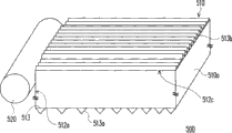
本发明进一步提出应用前述多种导光板的背光模块。图6为本发明一实施例的一种背光模块的示意图。请参照图6,本实施例的背光模块500包括一导光板510以及一光源组520。此处的导光板510可以采用上述的导光板100、100a、200、300或本发明其它可能的导光板结构,而对于这些相似或可以相互替换之处不再多做说明。另外,导光板510的本体510a的一侧面512a作为入光面,而光源组520为一条状光源,配置于侧面512a旁。光源组520适于发出一光线,所述光线由侧面512a进入导光板510。本实施例中,在平行出光面512c的一投影平面上,光源组520的延伸方向与出光面512c的棱镜微结构513b的延伸方向实质上垂直,也就是说,作为入光面的侧面512a的法线的延伸方向与出光面512c的棱镜微结构513b的延伸方向实质上平行。The present invention further proposes a backlight module using the aforementioned light guide plates. FIG. 6 is a schematic diagram of a backlight module according to an embodiment of the present invention. Please refer to FIG. 6 , the
图7为本发明另一实施例的一种背光模块的示意图。请参照图7,本实施例的背光模块600包括一导光板610以及一光源组620。此处的导光板610同样可以采用上述的导光板100、100a、200、300或本发明其它可能的导光板结构,而对于这些相似或可以相互替换之处不再多做说明。另外,导光板610的本体610a相对的两个侧面612a与612b作为入光面,而光源组620包括两个条状光源,分别配置于两个侧面612a与612b旁。光源组620适于发出光线由侧面612a与612b进入导光板610。值得注意的是,本实施例中在平行出光面612c的一投影平面上,光源组620的延伸方向与出光面612c的棱镜微结构613b的延伸方向实质上垂直,也就是说,作为入光面的侧面612a或612b的法线的延伸方向与出光面512b的棱镜微结构613b的延伸方向实质上平行。FIG. 7 is a schematic diagram of a backlight module according to another embodiment of the present invention. Please refer to FIG. 7 , the backlight module 600 of this embodiment includes a light guide plate 610 and a
在上述多个实施例中,考虑到导光板510或610离光源组520或620较远处会有光源衰减的问题,因此可以设计让底面513或613的棱镜微结构513a或613a的分布密度沿着远离入光面512、612a或612b的方向递增,其中图6的棱镜微结构513a便是沿单方向递增,而图7的棱镜微结构613a是由两入光面612a与612b朝向导光板610的中央递增,以此提高离光源组520或620较远处的出光效率。In the above-mentioned multiple embodiments, considering the light source attenuation problem that the
此外,由前述实施利可知导光板510或610底面513或613的棱镜微结构的高度、深度或其它部分的棱镜微结构的分布密度也会影响出光效率,因此还可以依据光源组520或620的配置方式来设计棱镜微结构。例如,底面513或613上的棱镜微结构513a或613a的高度或深度沿着远离入光面512a、612a或612b的方向递增,也就是离光源越远,导光板底部的微结构越明显,棱镜微结构的变化仅是举例,可依实际需求做调整。另外,条状光源可为荧光灯管、发光二极管灯条或其它相近光源,但不限于此,可依实际需求调整其类别。In addition, it can be known from the aforementioned implementation that the height and depth of the prism microstructures on the
图8为本发明又一实施例一种背光模块的示意图。图9为本发明其它实施例一种背光模块的示意图。请同时参照图8及图9,背光模块700与图7的背光模块600结构上相类似,而背光模块800与图6的背光模块500结构上相类似。因此相同的组件标以相同的附图标记,其中最大的不同在于背光模块700、800的本体形状。图8中的背光模块700其导光板本体610b的厚度由外围朝向中央逐渐递减。图9中背光模块800的导光板本体610c的形状为一楔形。FIG. 8 is a schematic diagram of a backlight module according to yet another embodiment of the present invention. FIG. 9 is a schematic diagram of a backlight module according to another embodiment of the present invention. Please refer to FIG. 8 and FIG. 9 at the same time. The
除此之外,与图7中的背光模块600相同,图8的背光模块700底面613的棱镜微结构613a,其排列的密度是由两入光面612a与612b朝向导光板710、810的中央递增,另外,与图6中的背光模块500相同,图9的背光模块800底面613的棱镜微结构613a,其排列的密度往远离光源方向递增。以此上述微结构的排列疏密,来提高离光源组620较远处的出光效率。In addition, similar to the backlight module 600 in FIG. 7 , the arrangement density of the
综上所述,本发明在导光板上制作棱镜微结构,其中导光板的出光面上具有多种不同顶角的棱镜微结构,并可进一步设计一缓冲区,以使导光板的出光效率提升以及视角问题获得改善。此外,导光板底面的棱镜微结构配合出光面的不同区域做高度或深度变化,使得出光面上某些具有较大顶角的棱镜微结构的区域,其出光效率较低的问题也可以同时获得补偿。另外,具有上述导光板结构的背光模块,配合光源的配置,导光板上的棱镜微结构的高度、深度或是分布密度亦跟着变化,与采用现有导光板的背光模块相较之下,其出光效率较佳,且混光较均匀。In summary, the present invention fabricates prism microstructures on the light guide plate, wherein the light emitting surface of the light guide plate has a variety of prism microstructures with different apex angles, and a buffer zone can be further designed to improve the light output efficiency of the light guide plate And the viewing angle problem is improved. In addition, the prism microstructure on the bottom of the light guide plate can be adjusted in height or depth according to different regions of the light-emitting surface, so that the problem of low light-extracting efficiency in some regions of the light-emitting surface with prism microstructures with large vertex angles can also be solved at the same time. compensate. In addition, for the backlight module with the above-mentioned light guide plate structure, the height, depth, or distribution density of the prism microstructures on the light guide plate will also change in accordance with the configuration of the light source. Compared with the backlight module using the existing light guide plate, its The light extraction efficiency is better, and the light mixing is more uniform.
虽然本发明已以实施例披露如上,然其并非用以限定本发明,任何所属技术领域中具有通常知识的人员,在不脱离本发明的精神和范围内,可作些许的更动与润饰,因此本发明的保护范围当视所附的权利要求书所界定的范围为准。Although the present invention has been disclosed above with embodiments, it is not intended to limit the present invention. Any person with ordinary knowledge in the technical field can make some changes and modifications without departing from the spirit and scope of the present invention. Therefore, the scope of protection of the present invention should be determined by the scope defined by the appended claims.
Claims (19)
Priority Applications (1)
| Application Number | Priority Date | Filing Date | Title |
|---|---|---|---|
| CN2008101797523A CN101413641B (en) | 2008-12-03 | 2008-12-03 | Light guide plate and backlight module |
Applications Claiming Priority (1)
| Application Number | Priority Date | Filing Date | Title |
|---|---|---|---|
| CN2008101797523A CN101413641B (en) | 2008-12-03 | 2008-12-03 | Light guide plate and backlight module |
Publications (2)
| Publication Number | Publication Date |
|---|---|
| CN101413641A true CN101413641A (en) | 2009-04-22 |
| CN101413641B CN101413641B (en) | 2011-04-06 |
Family
ID=40594302
Family Applications (1)
| Application Number | Title | Priority Date | Filing Date |
|---|---|---|---|
| CN2008101797523A Active CN101413641B (en) | 2008-12-03 | 2008-12-03 | Light guide plate and backlight module |
Country Status (1)
| Country | Link |
|---|---|
| CN (1) | CN101413641B (en) |
Cited By (14)
| Publication number | Priority date | Publication date | Assignee | Title |
|---|---|---|---|---|
| CN102759772A (en) * | 2012-04-18 | 2012-10-31 | 深圳市华星光电技术有限公司 | Light guide plate and corresponding backlight module |
| WO2013143094A1 (en) * | 2012-03-26 | 2013-10-03 | 深圳市华星光电技术有限公司 | Backlight module and liquid crystal display |
| CN105116598A (en) * | 2015-09-11 | 2015-12-02 | 青岛海信电器股份有限公司 | Backlight module, prismatic lens and television set |
| CN105334669A (en) * | 2015-12-09 | 2016-02-17 | 青岛海信电器股份有限公司 | Backlight module and liquid crystal display device |
| TWI560479B (en) * | 2015-07-07 | 2016-12-01 | Chi Mei Corp | Light guide plate, and backlight module and liquid crystal display apparatus using the same |
| CN106483713A (en) * | 2016-12-27 | 2017-03-08 | 惠科股份有限公司 | Backlight module |
| CN106526970A (en) * | 2016-12-27 | 2017-03-22 | 惠科股份有限公司 | Liquid crystal display device |
| WO2020062594A1 (en) * | 2018-09-30 | 2020-04-02 | 惠科股份有限公司 | Polarizing plate and display device |
| WO2020062587A1 (en) * | 2018-09-30 | 2020-04-02 | 惠科股份有限公司 | Polarization plate and display device |
| CN111290061A (en) * | 2020-04-28 | 2020-06-16 | 深圳市汇顶科技股份有限公司 | Optical diffusion sheet, light source device, and distance measuring device |
| CN113448125A (en) * | 2021-07-16 | 2021-09-28 | 合肥京东方光电科技有限公司 | Backlight module and display device |
| CN113900299A (en) * | 2021-09-22 | 2022-01-07 | 北海惠科光电技术有限公司 | Display module and display device |
| CN115236792A (en) * | 2022-05-30 | 2022-10-25 | 达运精密工业股份有限公司 | Light guide plate and backlight module |
| CN116125704A (en) * | 2022-12-29 | 2023-05-16 | 惠州华星光电显示有限公司 | Prism sheet and display module |
-
2008
- 2008-12-03 CN CN2008101797523A patent/CN101413641B/en active Active
Cited By (22)
| Publication number | Priority date | Publication date | Assignee | Title |
|---|---|---|---|---|
| WO2013143094A1 (en) * | 2012-03-26 | 2013-10-03 | 深圳市华星光电技术有限公司 | Backlight module and liquid crystal display |
| CN102759772A (en) * | 2012-04-18 | 2012-10-31 | 深圳市华星光电技术有限公司 | Light guide plate and corresponding backlight module |
| TWI560479B (en) * | 2015-07-07 | 2016-12-01 | Chi Mei Corp | Light guide plate, and backlight module and liquid crystal display apparatus using the same |
| CN105116598A (en) * | 2015-09-11 | 2015-12-02 | 青岛海信电器股份有限公司 | Backlight module, prismatic lens and television set |
| CN105116598B (en) * | 2015-09-11 | 2018-09-28 | 青岛海信电器股份有限公司 | A kind of backlight module, prismatic lens and television set |
| CN105334669A (en) * | 2015-12-09 | 2016-02-17 | 青岛海信电器股份有限公司 | Backlight module and liquid crystal display device |
| CN105334669B (en) * | 2015-12-09 | 2018-12-28 | 青岛海信电器股份有限公司 | A kind of backlight module and liquid crystal display |
| CN106526970B (en) * | 2016-12-27 | 2020-05-08 | 惠科股份有限公司 | Liquid crystal display device |
| CN106483713A (en) * | 2016-12-27 | 2017-03-08 | 惠科股份有限公司 | Backlight module |
| CN106526970A (en) * | 2016-12-27 | 2017-03-22 | 惠科股份有限公司 | Liquid crystal display device |
| WO2018120850A1 (en) * | 2016-12-27 | 2018-07-05 | 惠科股份有限公司 | Backlight module |
| WO2020062594A1 (en) * | 2018-09-30 | 2020-04-02 | 惠科股份有限公司 | Polarizing plate and display device |
| WO2020062587A1 (en) * | 2018-09-30 | 2020-04-02 | 惠科股份有限公司 | Polarization plate and display device |
| CN111290061A (en) * | 2020-04-28 | 2020-06-16 | 深圳市汇顶科技股份有限公司 | Optical diffusion sheet, light source device, and distance measuring device |
| CN113448125A (en) * | 2021-07-16 | 2021-09-28 | 合肥京东方光电科技有限公司 | Backlight module and display device |
| CN113448125B (en) * | 2021-07-16 | 2025-07-04 | 合肥京东方光电科技有限公司 | Backlight module and display device |
| CN113900299A (en) * | 2021-09-22 | 2022-01-07 | 北海惠科光电技术有限公司 | Display module and display device |
| CN115236792A (en) * | 2022-05-30 | 2022-10-25 | 达运精密工业股份有限公司 | Light guide plate and backlight module |
| US12345910B2 (en) | 2022-05-30 | 2025-07-01 | Darwin Precisions Corporation | Light guide plate and backlight module |
| CN116125704A (en) * | 2022-12-29 | 2023-05-16 | 惠州华星光电显示有限公司 | Prism sheet and display module |
| WO2024139422A1 (en) * | 2022-12-29 | 2024-07-04 | 惠州华星光电显示有限公司 | Prismatic lens and display module |
| US12339487B2 (en) | 2022-12-29 | 2025-06-24 | Huizhou China Star Optoelectronics Display Co., Ltd. | Prism sheet and display module |
Also Published As
| Publication number | Publication date |
|---|---|
| CN101413641B (en) | 2011-04-06 |
Similar Documents
| Publication | Publication Date | Title |
|---|---|---|
| CN101413641B (en) | Light guide plate and backlight module | |
| US8147111B2 (en) | Light guide plate and backlight module | |
| US7936420B2 (en) | Light guiding and dispersing plate and display device having the same | |
| CN102066836B (en) | Surface light source device and display | |
| US8353614B2 (en) | Backlight unit | |
| KR101164094B1 (en) | Backlight unit | |
| TWI429970B (en) | Light guide panel comprising wedge type rear prism for back light unit of tft-lcd | |
| US20090067178A1 (en) | Method of forming light-scattering dots inside the diffusion plate and light guide plate by laser engraving | |
| US20120134176A1 (en) | Backlight module and light guide plate thereof | |
| JP5927536B2 (en) | Light guide plate and surface light source device | |
| CN101498810B (en) | Light guide plate and backlight module using the light guide plate | |
| US10132966B2 (en) | Optical element including strip-shaped prisms, light guide plate, prism, backlight module and display device | |
| US20150268404A1 (en) | Backlight module | |
| US8408777B2 (en) | Planar illumination device | |
| CN105137522A (en) | Light guide plate, backlight module and display device | |
| JP2011138763A (en) | Light guide plate and method for manufacturing the same | |
| TW201350941A (en) | Light guide plate and backlight module using the same | |
| KR20110060348A (en) | Light Guide Plates and Backlight Units | |
| CN101660719A (en) | Backlight module | |
| EP1876480B1 (en) | Backlight unit of a liquid crystal display device | |
| CN202141827U (en) | Light guide plate, scanning backlight module and LCD | |
| CN202275180U (en) | Light guide plate, back light module group and liquid crystal display device | |
| CN111198415A (en) | Light guide plate and backlight module | |
| CN101126866A (en) | Direct type backlight module and liquid crystal display device comprising same | |
| KR20110071993A (en) | Light guide plate and backlight unit using the same |
Legal Events
| Date | Code | Title | Description |
|---|---|---|---|
| C06 | Publication | ||
| PB01 | Publication | ||
| C10 | Entry into substantive examination | ||
| SE01 | Entry into force of request for substantive examination | ||
| C14 | Grant of patent or utility model | ||
| GR01 | Patent grant |