CN101430077A - Lamp - Google Patents

Lamp Download PDF

Info

Publication number
CN101430077A
CN101430077A CNA2007102023987A CN200710202398A CN101430077A CN 101430077 A CN101430077 A CN 101430077A CN A2007102023987 A CNA2007102023987 A CN A2007102023987A CN 200710202398 A CN200710202398 A CN 200710202398A CN 101430077 A CN101430077 A CN 101430077A
Authority
CN
China
Prior art keywords
light
lamp
light source
cover
oxide
Prior art date
Legal status (The legal status is an assumption and is not a legal conclusion. Google has not performed a legal analysis and makes no representation as to the accuracy of the status listed.)
Granted
Application number
CNA2007102023987A
Other languages
Chinese (zh)
Other versions
CN101430077B (en
Inventor
赖志铭
Current Assignee (The listed assignees may be inaccurate. Google has not performed a legal analysis and makes no representation or warranty as to the accuracy of the list.)
Foxsemicon Integrated Technology Shanghai Inc
Foxsemicon Integrated Technology Inc
Original Assignee
Foxsemicon Integrated Technology Shanghai Inc
Foxsemicon Integrated Technology Inc
Priority date (The priority date is an assumption and is not a legal conclusion. Google has not performed a legal analysis and makes no representation as to the accuracy of the date listed.)
Filing date
Publication date
Application filed by Foxsemicon Integrated Technology Shanghai Inc, Foxsemicon Integrated Technology Inc filed Critical Foxsemicon Integrated Technology Shanghai Inc
Priority to CN2007102023987A priority Critical patent/CN101430077B/en
Priority to US11/964,826 priority patent/US7490955B1/en
Publication of CN101430077A publication Critical patent/CN101430077A/en
Application granted granted Critical
Publication of CN101430077B publication Critical patent/CN101430077B/en
Expired - Fee Related legal-status Critical Current
Anticipated expiration legal-status Critical

Links

Images

Classifications

    • FMECHANICAL ENGINEERING; LIGHTING; HEATING; WEAPONS; BLASTING
    • F21LIGHTING
    • F21VFUNCTIONAL FEATURES OR DETAILS OF LIGHTING DEVICES OR SYSTEMS THEREOF; STRUCTURAL COMBINATIONS OF LIGHTING DEVICES WITH OTHER ARTICLES, NOT OTHERWISE PROVIDED FOR
    • F21V17/00Fastening of component parts of lighting devices, e.g. shades, globes, refractors, reflectors, filters, screens, grids or protective cages
    • F21V17/10Fastening of component parts of lighting devices, e.g. shades, globes, refractors, reflectors, filters, screens, grids or protective cages characterised by specific fastening means or way of fastening
    • F21V17/104Fastening of component parts of lighting devices, e.g. shades, globes, refractors, reflectors, filters, screens, grids or protective cages characterised by specific fastening means or way of fastening using feather joints, e.g. tongues and grooves, with or without friction
    • FMECHANICAL ENGINEERING; LIGHTING; HEATING; WEAPONS; BLASTING
    • F21LIGHTING
    • F21KNON-ELECTRIC LIGHT SOURCES USING LUMINESCENCE; LIGHT SOURCES USING ELECTROCHEMILUMINESCENCE; LIGHT SOURCES USING CHARGES OF COMBUSTIBLE MATERIAL; LIGHT SOURCES USING SEMICONDUCTOR DEVICES AS LIGHT-GENERATING ELEMENTS; LIGHT SOURCES NOT OTHERWISE PROVIDED FOR
    • F21K9/00Light sources using semiconductor devices as light-generating elements, e.g. using light-emitting diodes [LED] or lasers
    • FMECHANICAL ENGINEERING; LIGHTING; HEATING; WEAPONS; BLASTING
    • F21LIGHTING
    • F21WINDEXING SCHEME ASSOCIATED WITH SUBCLASSES F21K, F21L, F21S and F21V, RELATING TO USES OR APPLICATIONS OF LIGHTING DEVICES OR SYSTEMS
    • F21W2131/00Use or application of lighting devices or systems not provided for in codes F21W2102/00-F21W2121/00
    • F21W2131/10Outdoor lighting
    • F21W2131/103Outdoor lighting of streets or roads
    • FMECHANICAL ENGINEERING; LIGHTING; HEATING; WEAPONS; BLASTING
    • F21LIGHTING
    • F21YINDEXING SCHEME ASSOCIATED WITH SUBCLASSES F21K, F21L, F21S and F21V, RELATING TO THE FORM OR THE KIND OF THE LIGHT SOURCES OR OF THE COLOUR OF THE LIGHT EMITTED
    • F21Y2115/00Light-generating elements of semiconductor light sources
    • F21Y2115/10Light-emitting diodes [LED]

Landscapes

  • Engineering & Computer Science (AREA)
  • General Engineering & Computer Science (AREA)
  • Physics & Mathematics (AREA)
  • Microelectronics & Electronic Packaging (AREA)
  • Optics & Photonics (AREA)
  • Non-Portable Lighting Devices Or Systems Thereof (AREA)

Abstract

本发明涉及一种便于安装及拆卸的灯具,该灯具包括至少一光源、一个灯座及一个光罩,该至少一光源安装在该灯座上且其发出的光线透过该光罩发射出去,该灯座沿第一方向开设至少一滑轨,该光罩包括至少一滑动件,该至少一滑动件与该至少一滑轨相配合以使该光罩滑动设置在该灯座上。该灯具通过设置灯座,以及将光罩滑动设置在灯座上而方便了对其进行安装及拆卸。

Figure 200710202398

The invention relates to a lamp which is easy to install and disassemble. The lamp comprises at least one light source, a lamp holder and a light cover. The at least one light source is installed on the lamp holder and the light emitted by it is emitted through the light cover. The lamp holder is provided with at least one sliding rail along the first direction, and the light cover includes at least one sliding piece. The at least one sliding piece cooperates with the at least one sliding rail so that the light cover is slidably arranged on the lamp holder. The light fixture facilitates its installation and disassembly by providing a lamp holder and slidingly setting the light shield on the lamp holder.

Figure 200710202398

Description

Light fixture
Technical field
The present invention relates to a kind of light fixture, relate in particular to a kind of outdoor lamp of installing and dismantling be convenient to.
Background technology
Light fixture is a communal facility indispensable in people's daily life as street lamp, thereby it can play illuminating effect out of doors and makes people outdoor normally free movable.The research of light fixture can be consulted people such as G.Miguel Ereu at IEEE system, transmission of electricity and distribution seminar in 2006 and exhibition (Transmission ﹠amp; Distribution Conference and Exposition:Latin America, 2006.TDC ' 06.IEEE/PES) the paper A Methodology to DetermineElectrical Energy Consumption in Street Lighting Systems that delivers on.
Because light emitting diode (Light Emitting Diode, LED) has long, advantage such as luminous efficiency is high, volume is little, pollution is low of life-span, so it is taken as perfect light source more and more and is widely used in various light fixtures, the especially outdoor lamp in recent years.Yet, outdoor lamp is owing to be in the open air, it is subjected to various natural causes easily, influence as the dust and the water droplet on rainy day of open air, in a single day these dusts and the globule are infected with and are exposed to outdoor outdoor lamp, it not only can have influence on the appearance looks elegant of light fixture, shelters from the light of light emitted and the brightness of light fixture is reduced easilier, thereby make people can't differentiate the road surface situation and lead to a disaster.Therefore, above-mentioned light fixture need regularly clean maintenance, and further safeguards when fault occurs to guarantee its operate as normal.Regrettably, existing light fixture, its structure is comparatively complicated usually, thereby causes its installation and dismounting inconvenience, and this has also increased the difficulty that it is cleaned maintenance and safeguards undoubtedly.
In view of this, be necessary to provide a kind of light fixture of installing and dismantling be convenient to.
Summary of the invention
To a kind of light fixture of installing and dismantling be convenient to be described with embodiment below.
A kind of light fixture, comprise at least one light source, a lamp socket and a light shield, this at least one light source is installed on this lamp socket and its light that sends is launched through this light shield, this lamp socket is offered at least one slide rail along first direction, this light shield comprises at least one sliding part, and this at least one sliding part matches so that this light shield is slidingly arranged on this lamp socket with this at least one slide rail.
With respect to prior art, this light fixture has the lamp socket of at least one slide rail by setting, and at least one sliding part that matches with at least one slide rail is set on light shield, is arranged on the lamp socket thereby light shield is slided, and with convenient light fixture is installed and is dismantled.
Description of drawings
Fig. 1 is the decomposition texture schematic diagram of the light fixture that provides of first embodiment of the invention.
Fig. 2 is the package assembly schematic diagram of the light fixture that provides of first embodiment of the invention.
Fig. 3 is the generalized section of the light shield of light fixture shown in Figure 1.
Fig. 4 is the light fixture that provides of first embodiment of the invention through after changing decomposition texture schematic diagram.
Fig. 5 is the decomposition texture schematic diagram of the light fixture that provides of second embodiment of the invention.
Fig. 6 is the mounting structure schematic diagram of the light fixture that provides of second embodiment of the invention.
The specific embodiment
Below in conjunction with accompanying drawing the embodiment of the invention is described in further detail.
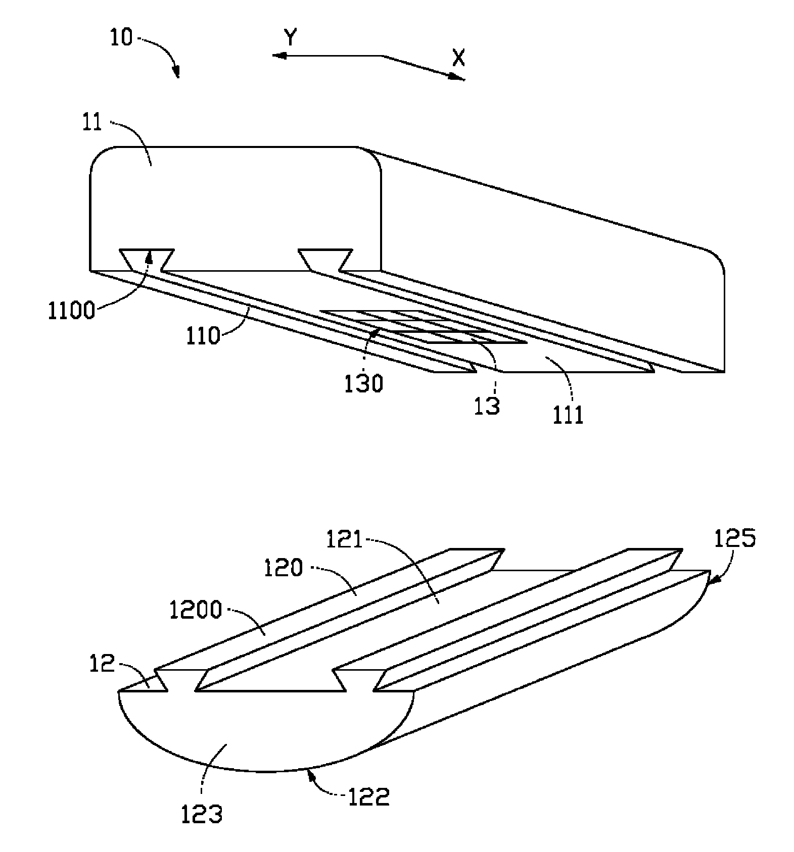
See also Fig. 1, a kind of light fixture 10 that first embodiment of the invention provides, it comprises 11, one light shields 12 of a lamp socket and at least one light source 13.
This lamp socket 11 is offered at least one slide rail 110 along directions X, and at least one sliding part 120 is set on this light shield 12, and this at least one sliding part 120 matches so that this light shield 12 is slidingly arranged on this lamp socket 11 with this at least one slide rail 110.In the present embodiment, offer two slide rails 110 on this lamp socket 11, and the cross section of every slide rail 110 is a polygon (be one trapezoidal) shown in Fig. 1, accordingly, two sliding parts 120 also are set on this light shield 12, its columnar projections for being complementary with slide rail 110, the cross section of this columnar projections also are a polygon (be one trapezoidal) shown in Fig. 1.By cooperating of this slide rail 110 and this sliding part 120, light shield 12 can slide along the slide rail on the lamp socket 11 110.In addition, the surface 1100 of this slide rail 110 can be distinguished with the surface 1200 of this sliding part 120 and further forms one deck silica gel (figure does not show), tight ness rating when engaging with this sliding part 120 to utilize this silica gel to increase this slide rail 110, and make slide rail 110 and sliding part 120 keep certain frictional force, thereby after preventing that lamp socket 11 and light shield 12 from fitting together, this lamp socket 11 breaks away from mutually with this light shield 12.
See also Fig. 2, an accepting groove 130 is set to accommodate at least one light source 13 on the surface 111 of these lamp socket 11 these light shields 12 of attaching, and when this light shield 12 is assembled on this lamp socket 11, this light shield 12 can be with these accepting groove 130 sealings, to prevent that at least one light source 13 in the accepting groove 130 is subjected to environmental contaminants, as the pollution of dust, thereby make this at least one light source 13 obtain preferable lighting environment.This at least one light source 13 can be at least one light emitting diode, and (Light emitting diode, LED), it also can be other light-emitting component, as incandescent lamp etc.
This light shield 12 can be used for adjusting by optics the direction of the light that this at least one light source 13 sends, for example, the light that optics is dispersed or this at least one light source 13 of optical focus sends, and adjust the illumination zone of this at least one light source 13, it comprises an incidence surface 121 and an exiting surface 122.During work, the light of these at least one light source 13 emissions is incident to this light shield 12 by this incidence surface 121, and then launches from the exiting surface 122 of this light shield 12.Particularly, this incidence surface 121 is a plane, and this exiting surface 12 is an arc surface.In addition, this light shield 12 is a transparent medium, its light transmittance (transmission rate) is greater than 90%, and refractive index (refraction rate) is between 1.4 and 1.7, and it can select polymethyl methacrylate (Polymethylmethacrylate for use, PMMA), polycarbonate (Poly Carbonate, PC), silicones (silicone), epoxy resin (epoxy), polyacrylate transparent materials such as (polyacrylate) are made, certainly, it also can adopt and be doped with zinc oxide (ZnO), boron oxide (B 2O 3), silica (SiO 2), niobium oxide (Nb 2O 5), sodium oxide molybdena (Na 2O) or lithia (Li 2O 5) glass make.Use above-mentioned material to make this light shield 12 and can alleviate the weight of light fixture 10 on the whole, thereby be convenient to this light fixture 10 is installed and dismantled.In addition, this light shield 12 also comprises two first sides 123,125, it is along being disposed at the relative both sides of this light shield 12 perpendicular to the Y direction of directions X and being connected with exiting surface 122 respectively, these two first sides 123,125 dispose a reflectance coating respectively so that at least one light source 13 light that send and that be incident on this reflectance coating are reflexed to exiting surface 122, and then launch, thereby limit at least one light source 13 along the radiation scope on the directions X by this exiting surface 122.
Please further consult Fig. 3, because the described light fixture 10 of present embodiment is arranged on outdoor usually, make the exiting surface 122 of this light shield 12 be exposed in the air and become easily infected by all contaminations, as dust etc., therefore, for the exiting surface 122 that makes light shield 12 keeps clean, can on the exiting surface 122 of this light shield 12, form a photocatalyst layer 124.This photocatalyst layer 124 can adopt photocatalyst material, and as titanium oxide, zinc oxide etc. are made, yet, because titanium oxide itself has more stable chemical property and lower toxicity than other photocatalyst materials such as zinc oxide, so, can preferably adopt titanium oxide to make this photocatalyst layer 124.
In addition, in order to prevent that photocatalyst layer 124 and light shield 12 from directly contacting chemical reaction taking place, thereby damage light shield 12, can between the exiting surface 122 of this light shield 12 and photocatalyst layer 124 protective clear layer 126 be set further.This protective clear layer 126 optionally utilizes dielectric material, makes as aluminium oxide, silica, silicon nitride etc.
When other pollutants such as dust arrive light fixture 10 and are adsorbed on the photocatalyst layer 124, on the one hand, the photoemissive UV-irradiation of the sun is on this photocatalyst layer 124, it can be photocatalyst layer 124 absorptions and excites, thereby produce separable electronics and hole, reaction such as this electronics and hole and water, oxidation produces the active material of tool oxidability (as crossing oxonium ion O2 -And hydroxyl free radical OH -), this active material can decompose and is adsorbed in the pollutant on the photocatalyst layer 124 and its adhesive ability is died down, and because the described light fixture 10 of present embodiment is positioned over outdoorly usually, takes away so can make full use of the rainwater pollutant cleaning that adhesive force is extremely weak; On the other hand, because this photocatalyst layer 124 can produce Superhydrophilic after absorbing the photoemissive ultraviolet light of the sun, so when rainwater contact photocatalyst layer 124, it can enter the gap between pollutant and the photocatalyst layer 124 easily and wash this pollutant.
In the present embodiment, the slide rail of being offered on the lamp socket 11 of this light fixture 10 110 also can be other shape, and cylindrical slide rail as shown in Figure 4 (promptly the cross section of this slide rail 110 is a circular arc) slides along the slide rail on the lamp socket 11 110 as long as be convenient to light shield 12.
See also Fig. 5, the described light fixture 20 of second embodiment of the invention, the described light fixture of itself and first embodiment of the invention 10 is basic identical, difference is: the light shield 22 of this light fixture 20 further comprises two second sides 227,228, and it also is connected with exiting surface 222 respectively along the relative both sides that the Y direction is disposed at this light shield 22, further, this light fixture 20 is provided with a block 25 that links to each other with sliding part 220, and a baffle plate 26 that links to each other with lamp socket 21.
Dispose a reflectance coating on these two second sides 227,228 respectively so that at least one light source 23 light that send and that be incident on this reflectance coating are reflexed to exiting surface 222, and then launch, thereby limit at least one light source 23 along the radiation scope on the Y direction from this exiting surface 222.Particularly, these two second sides 227,228 form an angle α, and this angle α preferably can be greater than 70 ° less than 140 °.
When sliding part 220 with after slide rail 210 cooperates, this block 25 can further shield to this at least one light source 23, makes at least one light source 23 avoid environmental contaminants, as the pollution of dust.
Please further consult Fig. 6, during use, this light fixture 10 is arranged at outdoor by a support arm 30, and itself and horizontal plane have an elevation angle β usually, therefore, by this baffle plate 26 is set, can work the effect of blocking to rainwater, thereby this light fixture 20 is shielded
The light fixture 10,20 that first and second embodiment of the present invention is provided, it has the lamp socket 11,21 of at least one slide rail 110,210 by setting, and at least one sliding part 120,220 that setting matches with at least one slide rail 110,210 on light shield 12,22, be arranged on the lamp socket 11,21 thereby light shield 12,22 is slided, light fixture 10,20 installed and dismantled with convenient
Be understandable that, for the person of ordinary skill of the art, can technical conceive according to the present invention make the change and the distortion of other various correspondences, and all these change the protection domain that all should belong to claim of the present invention with distortion.

Claims (13)

【权利要求1】一种灯具,其包括至少一光源、一个灯座及一个光罩,该至少一光源安装在该灯座上且其发出的光线透过该光罩发射出去,该灯座沿第一方向开设至少一滑轨,该光罩包括至少一滑动件,该至少一滑动件与该至少一滑轨相配合以使该光罩滑动设置在该灯座上。[Claim 1] A lamp comprising at least one light source, a lamp holder and a light cover, the at least one light source is installed on the lamp holder and the light emitted by it is emitted through the light cover, the lamp holder is along the At least one sliding rail is provided in the first direction, and the light cover includes at least one sliding piece, and the at least one sliding piece cooperates with the at least one sliding track so that the light cover is slidably arranged on the lamp holder. 【权利要求2】如权利要求1所述的灯具,其特征在于,该光罩包括一入光面及一出光面,该至少一光源发出的光线通过该入光面入射至该光罩,进而从该光罩的出光面出射。[Claim 2] The lamp according to claim 1, wherein the light cover comprises a light incident surface and a light output surface, the light emitted by the at least one light source enters the light cover through the light incident surface, and then Emit from the light-emitting surface of the mask. 【权利要求3】如权利要求1所述的灯具,其特征在于,该滑轨与该滑动件之间形成一层硅胶。[Claim 3] The lamp as claimed in claim 1, wherein a layer of silica gel is formed between the sliding rail and the sliding member. 【权利要求4】如权利要求1所述的灯具,其特征在于,该灯座贴附该光罩的表面上开设一个收容槽以收容该至少一光源。[Claim 4 ] The lamp as claimed in claim 1 , wherein a receiving groove is formed on the surface of the lamp holder attached to the light cover to accommodate the at least one light source. 【权利要求5】如权利要求1所述的灯具,其特征在于,该至少一滑轨的横截面为多边形或圆柱形,且该至少一滑动件的横截面为与该至少一滑轨的横截面相对应的多边形或圆柱形。[Claim 5] The lamp according to claim 1, wherein the cross section of the at least one sliding rail is polygonal or cylindrical, and the cross section of the at least one sliding member is the same as the cross section of the at least one sliding rail Sections correspond to polygons or cylinders. 【权利要求6】如权利要求1所述的灯具,其特征在于,该至少一光源为LED光源。[Claim 6] The lamp as claimed in claim 1, wherein the at least one light source is an LED light source. 【权利要求7】如权利要求1所述的灯具,其特征在于,该光罩的材料选自聚甲基丙烯酸甲酯、聚碳酸脂、硅树脂、环氧树脂、聚丙烯酸脂,及掺杂有氧化锌、氧化硼、氧化硅、氧化铌、氧化钠或氧化锂的玻璃。[Claim 7] The lamp according to claim 1, wherein the material of the mask is selected from polymethyl methacrylate, polycarbonate, silicone resin, epoxy resin, polyacrylate, and doped Glasses with zinc oxide, boron oxide, silicon oxide, niobium oxide, sodium oxide or lithium oxide. 【权利要求8】如权利要求1所述的灯具,其特征在于,该光罩包括两个第一侧面,其沿垂直于第一方向的第二方向配置于该光罩的相对的两侧且分别与出光面相连接,该两个第一侧面分别配置一反射膜以将至少一光源发出的且入射至该反射膜上的光线反射至出光面并发射出去,从而限制至少一光源沿第一方向上的辐射范围。[Claim 8] The lamp as claimed in claim 1, wherein the light shield comprises two first sides, which are disposed on opposite sides of the light shield along a second direction perpendicular to the first direction and The two first side surfaces are respectively connected with a reflective film to reflect the light emitted by at least one light source and incident on the reflective film to the light output surface and emit it, thereby restricting at least one light source from moving along the first direction. upward radiating range. 【权利要求9】如权利要求1所述的灯具,其特征在于,该光罩进一步包括两个第二侧面,其沿第一方向配置于该光罩的相对的两侧且分别与出光面相连接,该两个第二侧面分别配置一反射膜以将至少一光源发出的且入射至该反射膜上的光线反射至出光面并发射出去,从而限制至少一光源沿第二方向上的辐射范围。[Claim 9] The lamp according to claim 1, wherein the light cover further comprises two second side surfaces, which are arranged on opposite sides of the light cover along the first direction and are respectively connected to the light-emitting surface The two second side surfaces are respectively equipped with a reflective film to reflect the light emitted by at least one light source and incident on the reflective film to the light-emitting surface and emitted, thereby limiting the radiation range of the at least one light source along the second direction. 【权利要求10】如权利要求2所述的灯具,其特征在于,该光罩的出光面上设置一光触媒层。[Claim 10] The lamp as claimed in claim 2, wherein a photocatalyst layer is arranged on the light emitting surface of the light cover. 【权利要求11】如权利要求9所述的灯具,其特征在于,该两个第二侧面形成一夹角,该夹角大于70度而小于140度。[Claim 11] The lamp as claimed in claim 9, wherein the two second side surfaces form an included angle, and the included angle is greater than 70 degrees and less than 140 degrees. 【权利要求12】如权利要求10所述的灯具,其特征在于,该灯具进一步包括一个透明保护层,该透明保护层设置在该光罩的出光面与该光触媒层之间。[Claim 12] The lamp according to claim 10, characterized in that the lamp further comprises a transparent protective layer, and the transparent protective layer is disposed between the light emitting surface of the light cover and the photocatalyst layer. 【权利要求13】如权利要求12所述的灯具,其特征在于,该透明保护层的材料选自氧化铝、氧化硅及氮化硅。[Claim 13] The lamp as claimed in Claim 12, wherein the material of the transparent protective layer is selected from aluminum oxide, silicon oxide and silicon nitride.
CN2007102023987A 2007-11-06 2007-11-06 Lamp Expired - Fee Related CN101430077B (en)

Priority Applications (2)

Application Number Priority Date Filing Date Title
CN2007102023987A CN101430077B (en) 2007-11-06 2007-11-06 Lamp
US11/964,826 US7490955B1 (en) 2007-11-06 2007-12-27 LED lamp

Applications Claiming Priority (1)

Application Number Priority Date Filing Date Title
CN2007102023987A CN101430077B (en) 2007-11-06 2007-11-06 Lamp

Publications (2)

Publication Number Publication Date
CN101430077A true CN101430077A (en) 2009-05-13
CN101430077B CN101430077B (en) 2011-11-09

Family

ID=40349252

Family Applications (1)

Application Number Title Priority Date Filing Date
CN2007102023987A Expired - Fee Related CN101430077B (en) 2007-11-06 2007-11-06 Lamp

Country Status (2)

Country Link
US (1) US7490955B1 (en)
CN (1) CN101430077B (en)

Cited By (5)

* Cited by examiner, † Cited by third party
Publication number Priority date Publication date Assignee Title
CN103453467A (en) * 2013-08-22 2013-12-18 苏州康华净化系统工程有限公司 LED (light-emitting diode) lighting lamp for workshop
CN107965737A (en) * 2014-02-27 2018-04-27 三菱电机株式会社 Ligthing paraphernalia and light source cell
CN108019693A (en) * 2016-11-03 2018-05-11 崔长生 A kind of self-power generation type integrated lamp
CN108368988A (en) * 2017-11-10 2018-08-03 陈锦焜 Simple opening and closing lampshade
CN115264428A (en) * 2021-08-10 2022-11-01 蔡双如 Lampshade for embedded lamp and embedded lamp comprising same

Families Citing this family (7)

* Cited by examiner, † Cited by third party
Publication number Priority date Publication date Assignee Title
USD650113S1 (en) * 2008-07-18 2011-12-06 3M Innovative Properties Company Lighting device
CN103115331B (en) * 2011-11-17 2015-05-06 海洋王照明科技股份有限公司 Lamp
ES1076242Y (en) * 2012-01-26 2012-05-16 Lopez Ricardo Tellez Linear lighting device
USD674965S1 (en) * 2012-01-27 2013-01-22 Hubbell Incorporated LED optical component
DE102013104240B4 (en) * 2013-04-26 2015-10-22 R. Stahl Schaltgeräte GmbH Explosion-proof arrangement of electrical and / or electronic components
CN105508963A (en) * 2016-01-27 2016-04-20 阮积聪 LOGO lamp of vehicle
CN119062954B (en) * 2024-09-09 2025-08-01 中山楚辉照明电器有限公司 System based on easy maintenance modularization LED street lamp

Family Cites Families (10)

* Cited by examiner, † Cited by third party
Publication number Priority date Publication date Assignee Title
CA2023699A1 (en) * 1990-08-21 1992-02-22 Lawrence A. Sears Stairlights
CN2223437Y (en) * 1995-04-10 1996-03-27 江照政 Lampshade of cooking fume remover
US6582103B1 (en) * 1996-12-12 2003-06-24 Teledyne Lighting And Display Products, Inc. Lighting apparatus
DE19721340A1 (en) * 1997-05-22 1998-12-17 Regiolux Fraenkische Leuchten Lamp fitting for at least one artificial light source, e.g. fluorescent tube
FR2765668A1 (en) * 1997-07-03 1999-01-08 Nathalie Couchat Lamp with interchangeable frameless paper or plastic shades
CN2356890Y (en) * 1999-03-12 2000-01-05 周守权 High-brightness changeable high lamp for indicating passenger-free in taxi
CH695956A5 (en) * 2001-04-02 2006-10-31 Agabekov Sa Lighting element.
DE10224895A1 (en) * 2002-06-04 2003-12-18 Roehm Gmbh Self-cleaning plastic body and method for its production
CN2588193Y (en) * 2002-11-13 2003-11-26 林志泽 Lamp with lampshade adjusting function
CN2588197Y (en) * 2002-12-03 2003-11-26 均侑实业股份有限公司 lampshade

Cited By (7)

* Cited by examiner, † Cited by third party
Publication number Priority date Publication date Assignee Title
CN103453467A (en) * 2013-08-22 2013-12-18 苏州康华净化系统工程有限公司 LED (light-emitting diode) lighting lamp for workshop
CN107965737A (en) * 2014-02-27 2018-04-27 三菱电机株式会社 Ligthing paraphernalia and light source cell
CN107965737B (en) * 2014-02-27 2019-11-05 三菱电机株式会社 Luminaire and light source unit
CN108019693A (en) * 2016-11-03 2018-05-11 崔长生 A kind of self-power generation type integrated lamp
CN108368988A (en) * 2017-11-10 2018-08-03 陈锦焜 Simple opening and closing lampshade
CN115264428A (en) * 2021-08-10 2022-11-01 蔡双如 Lampshade for embedded lamp and embedded lamp comprising same
CN115264428B (en) * 2021-08-10 2024-07-19 蔡双如 Lamp shade for recessed lamp and recessed lamp comprising same

Also Published As

Publication number Publication date
US7490955B1 (en) 2009-02-17
CN101430077B (en) 2011-11-09

Similar Documents

Publication Publication Date Title
CN101430077A (en) Lamp
CN102072443A (en) Indoor LED lighting lamp
CN201589106U (en) lamps
CN102884268A (en) Multilayer illuminated glass unit with light emitting diodes
KR101211731B1 (en) Secondary Optical Lens for Lamp
CN101368689B (en) outdoor lighting
EP4411207A1 (en) Illumination device
CN201589107U (en) lamps
CN201811106U (en) Light emitting diode (LED) ceiling lamp
CN101749638A (en) Indoor lamp
KR101344267B1 (en) Manufacturing method for recycling street lamp using illuminance source transfer and recycling street lamp using the same
CN202188443U (en) Optical Baffles for LED Outdoor Luminaires
JP6006019B2 (en) Lighting device
TWI482995B (en) Light collecting device and lighting equipment
JP2014049261A (en) Lighting device
RU139022U1 (en) GLASS FOR LAMP
CN202012803U (en) An LED street lamp with a large illumination angle
TW200923263A (en) Illumination device
CN213118657U (en) Stage lamp capable of preventing reflection
CN201589105U (en) Lamp
CN202065827U (en) Lamp box structure
CN208331804U (en) LED light spreadlight lens
CN223537462U (en) A new type of anti-glare double-beam street light
Hocheng et al. A brighter place: overview of microstructured sunlight guide
CN100567800C (en) Solar LED Lighting Devices and Solar Cells

Legal Events

Date Code Title Description
C06 Publication
PB01 Publication
C10 Entry into substantive examination
SE01 Entry into force of request for substantive examination
C14 Grant of patent or utility model
GR01 Patent grant
C56 Change in the name or address of the patentee
CP01 Change in the name or title of a patent holder

Address after: 201600 Shanghai City, Songjiang District Songjiang Industrial Zone West science and Technology Industrial Park No. 500 Wen Ji Lu

Patentee after: Foxsemicon Semiconductor Precision (Shanghai) Inc.

Patentee after: Foxsemicon Integrated Technology Inc.

Address before: 201600 Shanghai City, Songjiang District Songjiang Industrial Zone West science and Technology Industrial Park No. 500 Wen Ji Lu

Patentee before: Foxsemicon Semiconductor Precision (Shanghai) Inc.

Patentee before: Foxsemicon Integrated Technology Inc.

C17 Cessation of patent right
CF01 Termination of patent right due to non-payment of annual fee

Granted publication date: 20111109

Termination date: 20131106