CN101558236B - Wind driven electric power generator and method of constructing wind driven electric power generator - Google Patents
Wind driven electric power generator and method of constructing wind driven electric power generator Download PDFInfo
- Publication number
- CN101558236B CN101558236B CN2008800009973A CN200880000997A CN101558236B CN 101558236 B CN101558236 B CN 101558236B CN 2008800009973 A CN2008800009973 A CN 2008800009973A CN 200880000997 A CN200880000997 A CN 200880000997A CN 101558236 B CN101558236 B CN 101558236B
- Authority
- CN
- China
- Prior art keywords
- nacelle
- split body
- cover
- power generator
- frame
- Prior art date
- Legal status (The legal status is an assumption and is not a legal conclusion. Google has not performed a legal analysis and makes no representation as to the accuracy of the status listed.)
- Expired - Fee Related
Links
Images



Classifications
-
- F—MECHANICAL ENGINEERING; LIGHTING; HEATING; WEAPONS; BLASTING
- F03—MACHINES OR ENGINES FOR LIQUIDS; WIND, SPRING, OR WEIGHT MOTORS; PRODUCING MECHANICAL POWER OR A REACTIVE PROPULSIVE THRUST, NOT OTHERWISE PROVIDED FOR
- F03D—WIND MOTORS
- F03D1/00—Wind motors with rotation axis substantially parallel to the air flow entering the rotor
- F03D1/06—Rotors
-
- F—MECHANICAL ENGINEERING; LIGHTING; HEATING; WEAPONS; BLASTING
- F03—MACHINES OR ENGINES FOR LIQUIDS; WIND, SPRING, OR WEIGHT MOTORS; PRODUCING MECHANICAL POWER OR A REACTIVE PROPULSIVE THRUST, NOT OTHERWISE PROVIDED FOR
- F03D—WIND MOTORS
- F03D13/00—Assembly, mounting or commissioning of wind motors; Arrangements specially adapted for transporting wind motor components
- F03D13/10—Assembly of wind motors; Arrangements for erecting wind motors
-
- F—MECHANICAL ENGINEERING; LIGHTING; HEATING; WEAPONS; BLASTING
- F05—INDEXING SCHEMES RELATING TO ENGINES OR PUMPS IN VARIOUS SUBCLASSES OF CLASSES F01-F04
- F05B—INDEXING SCHEME RELATING TO WIND, SPRING, WEIGHT, INERTIA OR LIKE MOTORS, TO MACHINES OR ENGINES FOR LIQUIDS COVERED BY SUBCLASSES F03B, F03D AND F03G
- F05B2240/00—Components
- F05B2240/10—Stators
- F05B2240/14—Casings, housings, nacelles, gondels or the like, protecting or supporting assemblies there within
-
- Y—GENERAL TAGGING OF NEW TECHNOLOGICAL DEVELOPMENTS; GENERAL TAGGING OF CROSS-SECTIONAL TECHNOLOGIES SPANNING OVER SEVERAL SECTIONS OF THE IPC; TECHNICAL SUBJECTS COVERED BY FORMER USPC CROSS-REFERENCE ART COLLECTIONS [XRACs] AND DIGESTS
- Y02—TECHNOLOGIES OR APPLICATIONS FOR MITIGATION OR ADAPTATION AGAINST CLIMATE CHANGE
- Y02E—REDUCTION OF GREENHOUSE GAS [GHG] EMISSIONS, RELATED TO ENERGY GENERATION, TRANSMISSION OR DISTRIBUTION
- Y02E10/00—Energy generation through renewable energy sources
- Y02E10/70—Wind energy
- Y02E10/72—Wind turbines with rotation axis in wind direction
-
- Y—GENERAL TAGGING OF NEW TECHNOLOGICAL DEVELOPMENTS; GENERAL TAGGING OF CROSS-SECTIONAL TECHNOLOGIES SPANNING OVER SEVERAL SECTIONS OF THE IPC; TECHNICAL SUBJECTS COVERED BY FORMER USPC CROSS-REFERENCE ART COLLECTIONS [XRACs] AND DIGESTS
- Y10—TECHNICAL SUBJECTS COVERED BY FORMER USPC
- Y10S—TECHNICAL SUBJECTS COVERED BY FORMER USPC CROSS-REFERENCE ART COLLECTIONS [XRACs] AND DIGESTS
- Y10S416/00—Fluid reaction surfaces, i.e. impellers
- Y10S416/50—Vibration damping features
-
- Y—GENERAL TAGGING OF NEW TECHNOLOGICAL DEVELOPMENTS; GENERAL TAGGING OF CROSS-SECTIONAL TECHNOLOGIES SPANNING OVER SEVERAL SECTIONS OF THE IPC; TECHNICAL SUBJECTS COVERED BY FORMER USPC CROSS-REFERENCE ART COLLECTIONS [XRACs] AND DIGESTS
- Y10—TECHNICAL SUBJECTS COVERED BY FORMER USPC
- Y10T—TECHNICAL SUBJECTS COVERED BY FORMER US CLASSIFICATION
- Y10T29/00—Metal working
- Y10T29/49—Method of mechanical manufacture
- Y10T29/49316—Impeller making
-
- Y—GENERAL TAGGING OF NEW TECHNOLOGICAL DEVELOPMENTS; GENERAL TAGGING OF CROSS-SECTIONAL TECHNOLOGIES SPANNING OVER SEVERAL SECTIONS OF THE IPC; TECHNICAL SUBJECTS COVERED BY FORMER USPC CROSS-REFERENCE ART COLLECTIONS [XRACs] AND DIGESTS
- Y10—TECHNICAL SUBJECTS COVERED BY FORMER USPC
- Y10T—TECHNICAL SUBJECTS COVERED BY FORMER US CLASSIFICATION
- Y10T29/00—Metal working
- Y10T29/49—Method of mechanical manufacture
- Y10T29/49636—Process for making bearing or component thereof
- Y10T29/49698—Demounting
Landscapes
- Engineering & Computer Science (AREA)
- Life Sciences & Earth Sciences (AREA)
- Sustainable Development (AREA)
- Sustainable Energy (AREA)
- Chemical & Material Sciences (AREA)
- Combustion & Propulsion (AREA)
- Mechanical Engineering (AREA)
- General Engineering & Computer Science (AREA)
- Wind Motors (AREA)
Abstract
Description
技术领域technical field
本发明是关于一种风力发电装置及风力发电装置的建设方法。 The invention relates to a wind power generating device and a construction method of the wind power generating device. the
背景技术Background technique
近年来,以增大风力发电装置的输出等为目的,试图使风车大型化。随着风车的大型化,到风车轮毂的高度变高,并且,机舱的重量也增加了。 In recent years, attempts have been made to increase the size of windmills for the purpose of increasing the output of wind power generators and the like. As the size of the windmill increases, the height to the hub of the windmill increases, and the weight of the nacelle also increases. the
为了应对这种变化,带来了建设风车时所用的起重机也大型化、建设费用增大的问题。 In order to cope with such changes, the cranes used in the construction of windmills have also become larger and the construction costs have increased. the
为了解决这些问题,人们提出了分割风车的旋转叶片、机舱等建设风车的方法(参照例如非专利文献1)。 In order to solve these problems, a method of constructing a windmill by dividing its rotor blades, nacelle, etc. has been proposed (see, for example, Non-Patent Document 1). the
根据上述方法,可抑制建设所用的起重机的大型化,进而抑制了建设费用的增大。 According to the above-mentioned method, it is possible to suppress an increase in the size of a crane used for construction, thereby suppressing an increase in construction cost. the
非专利文献1:“4种新提案”、02:分解机舱与分割叶片、(online)、平成18年10月5日检索、 Non-Patent Document 1: "Four New Proposals", 02: Decomposing the Nacelle and Segmenting Blades, (online), retrieved on October 5, 2018,
Internet<UPL:http://www.fhi.co.jp/ecotechnology/wind/tech/index.html> Internet <UPL: http://www.fhi.co.jp/ecotechnology/wind/tech/index.html>
根据上述方法,通过将机舱分割成架构部、传动机构部以及轮毂部的三个部分,可以抑制将这些部分提升到支柱前端的起重机的大型化。在该方法中,首先,将架构配置在支柱的前端上,之后,将传动机构部等从上方配置在架构部上。因此,架构部的上面是敞开的,以能够配置传动机构部等。 According to the method described above, by dividing the nacelle into three parts of the frame part, the transmission mechanism part, and the hub part, it is possible to suppress the enlargement of the crane that lifts these parts to the tip of the pillar. In this method, first, the frame is placed on the front end of the pillar, and then the transmission mechanism and the like are placed on the frame from above. Therefore, the upper surface of the frame part is opened so that the transmission mechanism part and the like can be arranged. the
也就是说,在建设当中,担心雨水等有可能从敞开的上面浸入架构部内,即使是小雨的天气,也有可能在风车的建设中产生故障。 That is to say, during construction, there is a concern that rainwater, etc. may infiltrate into the structural part from the open top, and even light rain may cause trouble during the construction of the windmill. the
进一步,由于传递轮毂部旋转的传动机构部安装在设有发电机等的架构部上,所以,有可能两者之间对准产生大的偏差。 Furthermore, since the transmission mechanism portion that transmits the rotation of the hub portion is attached to the frame portion on which the generator and the like are installed, there is a possibility that there is a large deviation in alignment between the two. the
本发明就是为了解决上述问题提出的,其目的是,提供一种可降低特别是大型风力发电装置的建设费用并且可缓和天气引起的对建设时间的限制的风力发电装置及风力发电装置的建设方法。 The present invention is proposed in order to solve the above-mentioned problems, and its object is to provide a wind power generation device and a construction method of a wind power generation device that can reduce the construction cost of a large-scale wind power generation device and alleviate the restriction on the construction time caused by the weather. . the
发明内容Contents of the invention
为了实现上述目的,本发明采用下述手段。 In order to achieve the above objects, the present invention employs the following means. the
本发明第1形式,提供一种风力发电装置,其特征在于,设置有:安装有多个风车旋转叶片,通过多个风车旋转叶片受到的风力被旋转驱动的旋翼毂;配置在支柱上,构成用于安装上述旋翼毂的机舱的前部分割体;安装在该前部分割体上,构成上述机舱的后部分割体;设置在上述前部分割体上,在上述旋翼毂与上述支柱之间支持作用在上述旋翼毂上的载荷的前部构架;设置在上述后部分割体上,安装在上述前部构架上的后部构架;覆盖上述前部分割体周围的前部盖;以及覆盖上述后部分割体周围的后部盖。 A first aspect of the present invention provides a wind power generator, which is characterized in that it is provided with: a rotor hub that is mounted with a plurality of windmill rotor blades and is rotationally driven by the wind force received by the plurality of windmill rotor blades; A front segment of the nacelle for mounting said rotor hub; mounted on said front segment, constituting said rear segment of said nacelle; disposed on said front segment, between said rotor hub and said strut a front frame supporting a load acting on the rotor hub; a rear frame provided on the rear segment and mounted on the front frame; a front cover covering the periphery of the front segment; and a cover covering the Rear cover around rear split body. the
根据本发明第1形式,由于发动机舱由前部分割体与后部分割构成,所以,与一体型的机舱比较,可实现建设风力发电装置时必要的起重机的小型化。进一步,用于搬运前部分割体与后部分割体的车辆,与搬运一体型的机舱的车辆比较,可用小型车辆。这样,不需要使用大型的起重机或车辆,所以,抑制了建设费用的增大。 According to the first aspect of the present invention, since the nacelle is composed of the front split body and the rear split body, it is possible to reduce the size of the crane necessary for building a wind power generator compared with an integral nacelle. Furthermore, the vehicle for transporting the front segment body and the rear segment body can be a smaller vehicle than the vehicle for transporting the integrated nacelle. In this way, it is not necessary to use a large-scale crane or a vehicle, so that an increase in construction cost is suppressed. the
由于前部分割体及后部分割体分别通过前部盖和后部盖覆盖,所以,在建设风力发电装置之际,不易受到天气的影响。例如,即使是雨天等,也能防止雨水向前部及后部分割体内部的浸入。 Since the front split body and the rear split body are respectively covered by the front cover and the rear cover, it is less likely to be affected by the weather when constructing the wind power generator. For example, even in rainy weather, it is possible to prevent rainwater from infiltrating into the inside of the front and rear divided bodies. the
在上述发明的第1形式中,希望上述前部构架通过铸造形成。 In the first aspect of the above-mentioned invention, it is desirable that the above-mentioned front frame is formed by casting. the
通过采用这样的措施,由于可提高前部构架形状的自由度,所以,前部构架可形成为适于支持作用在旋翼毂上的载荷的形状。因此,可防止前部构架重量的增加,防止用于风力发电装置的建设的起重机或车辆等的大型化。 By taking such a measure, since the degree of freedom of the shape of the front frame can be increased, the front frame can be formed in a shape suitable for supporting the load acting on the rotor hub. Therefore, an increase in the weight of the front frame can be prevented, and an increase in the size of a crane, a vehicle, and the like used for construction of the wind power generator can be prevented. the
在上述发明的第1形式中,优选的是,在上述前部分割体与上述支柱的前端之间,设置有使上述机舱和旋翼毂可围绕垂直轴线旋转的旋转分割体。 In the first aspect of the invention described above, preferably, a rotary split body for allowing the nacelle and the rotor hub to rotate around a vertical axis is provided between the front split body and the front end of the strut. the
通过采用这样的措施,通过使机舱及旋翼毂旋转的机构作为旋转分割体并从前部分割体分离,可实现前部分割体的小型化与轻量化。因此,可防止用于风力发电装置的建设的起重机、车辆等的大型化。 By adopting such a measure, the mechanism for rotating the nacelle and the rotor head can be separated from the front split body as a rotary split body, so that the size and weight of the front split body can be reduced. Therefore, it is possible to prevent enlargement of cranes, vehicles, and the like used in the construction of the wind power generator. the
进一步,通过设置旋转分割体,可将前部分割体的前部构架的形状形 成为更适于支持作用在旋翼毂上的载荷的形状。因此,可更有效地防止前部构架重量的增加,防止用于风力发电装置的建设的起重机或车辆等的大型化。 Furthermore, by providing the rotating split body, the shape of the front frame of the front split body can be formed into a shape more suitable for supporting the load acting on the rotor hub. Therefore, it is possible to more effectively prevent an increase in the weight of the front frame, and prevent an increase in the size of a crane, a vehicle, and the like used in the construction of the wind power generator. the
在上述发明的第1形式中,希望上述前部构架和上述后部构架的结合端配置在上述机舱的上述支柱侧,在上述前部分割体和上述后部分割体之间的至少相对上述结合端离开上述支柱的位置,形成上述前部构架与上述后部构架结合时的间隙,并且,设置有用于填埋该间隙的接合部。 In the first form of the above-mentioned invention, it is desirable that the joint end of the above-mentioned front frame and the above-mentioned rear frame is arranged on the side of the above-mentioned pillar of the above-mentioned nacelle. The position where the end is separated from the above-mentioned pillar forms a gap when the above-mentioned front frame and the above-mentioned rear frame are combined, and a joint portion for filling the gap is provided. the
通过采用这样的措施,由于前部分割体及后部分割体通过将前部构架与后部构架的结合端结合而结合。这时,在前部分割体及后部分割体上形成上述间隙,所以,使结合端的支柱侧的端部即下侧的端部分离,并且,可使从支柱离开的端部即上侧的端部接触。因此,用起重机提升后部分割体并与前部分割体连接时,很容易进行后部分割体的对准,很容易实现空中前部分割体与后部分割体的结合作业。 By taking such a measure, the front divided body and the rear divided body are joined by joining the joint ends of the front frame and the rear frame. At this time, the above-mentioned gap is formed on the front split body and the rear split body, so the end of the joint end on the side of the pillar, that is, the lower end, can be separated, and the end that is separated from the strut, that is, the upper side can be separated. end contact. Therefore, when the rear split body is lifted by a crane and connected to the front split body, the alignment of the rear split body is easy, and the coupling operation of the front split body and the rear split body in the air is easily realized. the
进一步,在前部分割体与后部分割体结合之后,由于上述间隙通过接合部填埋,所以,可防止雨水等向机舱内的浸入。 Furthermore, after the front section body and the rear section body are joined, since the above-mentioned gap is filled by the joint part, intrusion of rainwater etc. into the nacelle can be prevented. the
在上述发明的第1形式中,希望上述接合部是将覆盖上述前部分割体的前部盖和覆盖上述后部分割体的后部盖之间接合的盖接合部,在该盖接合部上设置有向上述机舱的内部延伸并且与上述前部盖接合的前部凸缘部以及向上述机舱的内部延伸并且与上述后部盖接合的后部凸缘部,构成上述前部凸缘部和上述后部凸缘部的面是互相交叉的面。 In the first aspect of the above-mentioned invention, it is desirable that the joint portion is a cover joint portion for joining the front cover covering the front divided body and the rear cover covering the rear divided body. A front flange extending into the nacelle and joined to the front cover and a rear flange extending in the nacelle and joined to the rear cover are provided to form the front flange and the rear flange. The surfaces of the rear flange portion are mutually intersecting surfaces. the
通过采用这样的措施,由于分别构成前部凸缘部和后部盖接合的面是相互交叉的,所以,即使前部盖和后部盖的相对位置不是一定的,也能用盖接合部填埋前部盖与后部盖的间隙。 By adopting such a measure, since the faces forming the junction of the front flange portion and the rear cover respectively intersect each other, even if the relative positions of the front cover and the rear cover are not constant, it is possible to fill the joint with the cover joint. Bury the gap between the front cover and the rear cover. the
例如,不论上述间隙变宽还是变窄,通过将盖接合部沿着相对上述间隙的宽度方向交叉的方向移动,可填埋间隙。进一步,即使在前部盖的面与后部盖的面构成台阶的情况下,通过盖接合部依然可填埋间隙。 For example, regardless of whether the gap is widened or narrowed, the gap can be filled by moving the lid joint portion in a direction intersecting with the width direction of the gap. Furthermore, even when the surface of the front cover and the surface of the rear cover form a step, the gap can still be filled by the cover joint. the
因此,不用再相对前部盖或后部盖额外地进行加工,可进行两盖的接合。进一步,可防止雨水从前部盖与后部盖之间向机舱漏雨。 Therefore, both covers can be joined without additional processing for the front cover or the rear cover. Further, rainwater can be prevented from leaking into the cabin from between the front cover and the rear cover. the
本发明第2形式,提供一种风力发电装置的建设方法,其特征在于,包括:在支柱上配置安装具有多个风车旋转叶片的旋翼毂的前部分割体的前部分割体安装工序;将与前部分割体一起构成机舱的后部分割体安装在 上述前部分割体上的后部分割体安装工序;以及在上述前部分割体与上述后部分割体之间的间隙中,配置用于填埋该间隙的接合部的接合部配置工序。 A second aspect of the present invention provides a method for constructing a wind power generator, characterized by comprising: a front split body installation step of arranging and mounting a front split body of a rotor hub having a plurality of wind turbine rotor blades on a strut; A rear split body installation process in which the rear split body constituting the nacelle together with the front split body is installed on the aforementioned front split body; and in the gap between the aforementioned front split body and the aforementioned rear split body, the A joint arrangement process for filling the joint in the gap. the
根据本发明第2形式,在将前部分割体安装在支柱上之后,将后部分割体安装在该前部分割体上,由此构成机舱,因此,与一体型的机舱的情况相比较,可实现建设风力发电装置时必要的起重机的小型化。进一步,搬运前部分割体与后部分割体的车辆,与搬运一体型的机舱的车辆比较,可用小型车辆。这样,不需要使用大型的起重机、车辆,所以,抑制了建设费用的增大。 According to the second aspect of the present invention, after the front split body is mounted on the pillar, the rear split body is mounted on the front split body to constitute the nacelle. Therefore, compared with the case of an integrated nacelle, It is possible to downsize the cranes necessary for the construction of wind power generation equipment. Furthermore, the vehicle for transporting the front section body and the rear section body can be a smaller vehicle than the vehicle for transporting the integrated nacelle. This eliminates the need to use large-scale cranes and vehicles, thereby suppressing an increase in construction costs. the
根据本发明第1形式的风力发电装置,由于发动机舱由前部分割体与后部分割构成,所以,可达到降低特别是大型风力发电装置的建设费用的效果。进一步,由于前部分割体及后部分割体分别通过前部盖和后部盖覆盖,所以,可实现缓和天气引起的对建设时间的限制的效果。 According to the wind power generator according to the first aspect of the present invention, since the nacelle is composed of the front split body and the rear split, it is possible to achieve the effect of reducing the construction cost of a large wind power generator in particular. Furthermore, since the front divided body and the rear divided body are respectively covered by the front cover and the rear cover, it is possible to achieve the effect of alleviating restrictions on construction time due to weather. the
根据本发明第2形式的风力发电装置的建设方法,在将前部分割体安装在支柱上之后,通过安装后部分割体而构成机舱,因此,可达到降低特别是大型风力发电装置的建设费用的效果。 According to the construction method of the wind power generation device of the second aspect of the present invention, after the front split body is installed on the pillar, the nacelle is formed by installing the rear split body, therefore, it is possible to reduce the construction cost of a large wind power generation device in particular. Effect. the
附图说明Description of drawings
图1是本发明一个实施形式的风力发电装置构成的说明图。 Fig. 1 is an explanatory view showing the configuration of a wind power generator according to an embodiment of the present invention. the
图2是说明图1的机舱结构的局部放大图。 FIG. 2 is a partially enlarged view illustrating the structure of the nacelle of FIG. 1 . the
图3是说明图2的机舱的各种组件构成的模式图(分割的示意图)。 FIG. 3 is a schematic diagram (separated schematic view) illustrating the configuration of various components of the nacelle of FIG. 2 . the
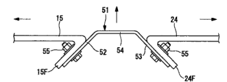
图4是用于说明图3的前部盖、盖接合部以及与后部盖的接合部的构成的模式图。 FIG. 4 is a schematic view for explaining the configuration of the front cover, the cover joint portion, and the joint portion with the rear cover in FIG. 3 . the
图5是说明图1的风力发电装置的机舱的建设方法的流程图。 Fig. 5 is a flowchart illustrating a method of constructing a nacelle of the wind power generator shown in Fig. 1 . the
图6是说明图1的机舱的建设方法的模式图。 Fig. 6 is a schematic diagram illustrating a method of constructing the nacelle of Fig. 1 . the
图7是说明图1的机舱的建设方法的模式图。 Fig. 7 is a schematic diagram illustrating a method of constructing the nacelle of Fig. 1 . the
图8是说明图1的机舱的建设方法的模式图。 Fig. 8 is a schematic diagram illustrating a method of constructing the nacelle of Fig. 1 . the
图9是说明图1的机舱的建设方法的模式图。 FIG. 9 is a schematic diagram illustrating a method of constructing the nacelle of FIG. 1 . the
图10是用于说明前部盖与后部盖之间间隔变窄情况下的构成示意图。 Fig. 10 is a schematic diagram for explaining a case where the space between the front cover and the rear cover is narrowed. the
图11是用于说明前部盖与后部盖之间间隔变宽情况下的构成示意图。 Fig. 11 is a schematic diagram for explaining a case where the gap between the front cover and the rear cover is widened. the
图12是用于说明前部盖的面的位置与后部盖的面的位置错位情况下构 成的示意图。 Fig. 12 is a schematic diagram for explaining the configuration when the position of the surface of the front cover and the position of the surface of the rear cover are misaligned. the
符号说明 Symbol Description
1-风力发电装置,2-支柱,3-机舱,5-旋翼毂,6-风车旋转叶片,11-前部组件(前部分割体),21-后部组件(后部分割体),31-旋转组件(旋转分割体),12-机舱台板(前部构架),16-前部结合端(结合端),15-前部盖,22-后部构架,25-后部结合端(结合端),24-后部盖,41-构架接合部,51-盖接合部,52-第1接合部凸缘(前部凸缘部),53-第2接合部凸缘(后部凸缘部),S2-前部组件安装工序(前部分割体安装工序),S3-后部组件安装工序(后部分割体安装工序),S4-接合部配置工序。 1-wind power generation device, 2-pillar, 3-nacelle, 5-rotor hub, 6-windmill rotating blade, 11-front assembly (front split body), 21-rear assembly (rear split body), 31 -rotating assembly (rotating split body), 12-cabin platform (front frame), 16-front joint end (joint end), 15-front cover, 22-rear frame, 25-rear joint end ( joint end), 24-rear cover, 41-frame joint, 51-cover joint, 52-first joint flange (front flange), 53-second joint flange (rear flange edge), S2-front assembly installation process (front split body installation process), S3-rear assembly installation process (rear split body installation process), S4-junction part configuration process. the
具体实施方式Detailed ways
参照图1~图12,说明本发明一实施形式的风力发电装置。 Referring to Figs. 1 to 12, a wind power generator according to an embodiment of the present invention will be described. the
图1是本发明实施形式的风力发电装置构成的说明图。 Fig. 1 is an explanatory diagram showing the configuration of a wind power generator according to an embodiment of the present invention. the
如图1所示,风力发电装置1是进行风力发电的装置。在该风力发电装置1中,设置有:立设在基础B上的支柱2;设置在支柱2上端的机舱3;可围绕大致水平的轴线转动且设置在机舱3上的旋翼毂5;用于覆盖旋翼毂5的头部盒盖4;以放射状围绕旋翼毂5的旋转轴线安装的多个风车旋转叶片6;以及通过旋翼毂5的旋转进行发电的发电设备7。 As shown in FIG. 1 , a wind power generator 1 is a device that generates wind power. In this wind power generation device 1, it is provided with: a
另外,在本实施形式中,虽然说明了适用于设置3个风车旋转叶片6的例子,但是,风车旋转叶片6的个数并不限于3个,也适用于2个的情况或3个以上的情况,并没有特别限定。 In addition, in this embodiment, although the example in which three wind
如图1所示,支柱2是构成为从基础B向上(图1的上方)延伸的柱状,例如,构成为将多个单元沿上下方向连结。在支柱2的最上部设有机舱3。在支柱2由多个单元构成的情况下,在设置于最上部的单元之上设置机舱3。 As shown in FIG. 1 , the
图2是说明图1的机舱3结构的局部放大图。 FIG. 2 is a partially enlarged view illustrating the structure of the nacelle 3 in FIG. 1 . the
机舱3如图1及图2所示,可旋转地支持着旋翼毂5,并且,内部容纳有通过旋翼毂5的旋转进行发电的发电设备7。 As shown in FIGS. 1 and 2 , the nacelle 3 rotatably supports the rotor hub 5 , and accommodates a power generator 7 inside which generates electricity by the rotation of the rotor hub 5 . the
机舱3大致由前部组件(前部分割体)11、后部组件(后部分割体)21以及旋转组件(旋转分割体)31的3个组件构成。 The nacelle 3 is roughly constituted by three units of a front unit (front split body) 11 , a rear unit (rear split body) 21 , and a rotation unit (rotation split body) 31 . the
图3是说明图2的机舱3的各种组件11、21、31构成的模式图。(分割 的示意图)。 FIG. 3 is a schematic diagram illustrating the configuration of
前部组件11配置在旋转组件31上,可旋转地支持着旋翼毂5。作为前部组件11的重量,在风力发电装置1为2000KW级的情况下,可例示为例如约60t。 The
如图3所示,在前部组件11上设置有机舱台板(前部构架)12;前部卷扬机用构架13;增速机14以及前部盖15。 As shown in FIG. 3 , a nacelle deck (front frame) 12 ; a
如图3所示,机舱台板12是将大致水平地安装在旋转组件31上端的台面部12A与从上方覆盖该台面部12A的壳体12B一体构成的铸件结构体。 As shown in FIG. 3 , the
在壳体12B上,在与旋翼毂5对置的位置(图3的左端部)形成第1开口部12H1,在与第1开口部12H1对置的位置(图3的右端部)形成第2开口部12H2。 In the
在机舱台板12的台面部12A的后侧端部(图3的右端部),设有用于固定下部构架22的前部结合端(结合端)16,在台面部12A及壳体12B上固定有前部卷扬机用构架13的前部柱部件17。 At the rear side end (the right end of FIG. 3 ) of the
前部卷扬机用构架13与后述的后部卷扬机用构架23及构架接合部41一起构成卷扬机用构架。前部卷扬机用构架13处在机舱台板12的上方,是将配置在前部盖15内部的杆状部件组合而成的。 The front hoist
在前部卷扬机用构架13上,设有固定在机舱台板12上的前部柱部件17和安装在前部柱部件17上端的前部梁部件18。 The front hoist
前部柱部件17在机舱台板12的两侧面,与后部柱部件26一起沿着机舱3的纵向并排配置着。 The
前部梁部件18沿着机舱3的纵向(图3的左右方向)延伸地配置着。 The
该前部梁部件18与后部梁部件27一起,发挥着设置于机舱3内的卷扬机大梁7W的纵行导轨的作用。 Together with the
在前部柱部件17与前部梁部件18的连接部,配置有为了提高前部卷扬机用构架13的结构强度的撑臂部件19。 A brace member 19 for increasing the structural strength of the
增速机14是将旋翼毂5的旋转对发电设备7增速并且传递的机构。增速机14配置在机舱台板12的内部,通过第1开口部12H1与旋翼毂5连接,通过第2开口部12H2与发电设备7连接。 The
前部盖15是覆盖前部组件11的盖,由例如FRP(纤维强化塑料)形成。前部盖15在机舱台板12与后部构架22结合之际,构成为在与后部盖 24之间形成间隙的形状。换言之,前部盖15的后端配置在比机舱台板12的后端更靠向旋翼毂5一侧。 The
图4是用于说明图3的前部盖15、盖接合部51以及与后部盖24的接合部的构成的模式图。 FIG. 4 is a schematic view for explaining the configuration of the
进一步,前部盖15的后端构成开口端,在开口端的周围,如图4所示,形成与后述的盖接合部51的第1接合部凸缘52结合的前部凸缘15F。 Furthermore, the rear end of the
前部凸缘15F为从前部盖15开始朝向机舱3的内部向旋翼毂5一侧(图4的左侧)倾斜的斜面。在前部凸缘15F上,形成朝向机舱3的内部延伸的长孔(图中未示),用于与盖接合部51接合的接合螺栓55从该长孔中穿过。 The
后部组件21安装在前部组件11的后端(图3的右侧端),其内部配置有发电设备7。作为后部组件21的重量,在风力发电装置1为1000KW级的情况下,可例示为例如约30t。 The
如图3所示,在后部组件21中设有后部构架22、后部卷扬机用构架23及后部盖24。 As shown in FIG. 3 , the
如图3所示,后部构架22是将发电设备7配置其上面的焊接结构。后部构架22从机舱台板12向后方(图3的右方向)延伸配置。 As shown in FIG. 3 , the
在后部构架22的前端部(图3的左端部),设有与机舱台板12结合的后部结合端(结合端)25,在后部构架22上,固定着后部卷扬机用构架23的后部柱部件26。 At the front end (the left end in FIG. 3 ) of the
后部卷扬机用构架23与上述前部卷扬机用构架13及构架接合部41一起,构成卷扬机用构架。后部卷扬机用构架23位于后部构架22的上方,是将配置在后部盖24内部的杆状部件组合而成的结构。 The rear hoist
在后部卷扬机用构架23上,设有固定在后部构架22上的后部柱部件26及将后部柱部件26上端连接在一起的后部梁部件27。 The rear hoist
后部柱部件26在后部构架22的两侧面,与前部柱部件17一起沿着机舱3的纵向并排配置。 The
后部梁部件27被配置为在纵向延伸并且与后部柱部件26的上端连接。该后部梁部件27与前部梁部件18一起,也发挥着设置于机舱3内的卷扬机大梁7W(参照图1)的纵行导轨的作用。 The
后部盖24是覆盖后部组件21的盖,与前部盖15同样,由例如FRP形成。 The
后部盖24在机舱台板12与后部构架22结合之际,构成为在与前部盖15之间形成间隙的形状。 The
进一步,后部盖24的前端构成开口端,在开口端的周围,如图4所示,形成与后述的盖接合部51的第2接合部凸缘53结合的后部凸缘24F。 Furthermore, the front end of the
后部凸缘24F为从后部盖24开始朝向机舱3的内部向后侧(图4的右侧)倾斜的斜面。在后部凸缘24F上,形成朝向机舱3的内部延伸的长孔(图中未示),用于与盖接合部51接合的接合螺栓55从该长孔中穿过。 The
构架接合部41埋在前部卷扬机用构架13和后部卷扬机用构架23之间,前部卷扬机用构架13和后部卷扬机用构架23一起,发挥着设置于机舱3内的卷扬机大梁7W的纵行导轨的作用。 The
如图4所示,盖接合部51是埋在前部盖15和后部盖24之间的间隙中的部件,由例如FRP形成。 As shown in FIG. 4 , the cover
在盖接合部51上,设有:与前部凸缘15F结合的第1接合部凸缘(前部凸缘部)52;与后部凸缘24F结合的第2接合部凸缘(后部凸缘部)53;以及将第1和第2接合部凸缘52、53连接在一起的接合部本体54。 On the cover
第1接合部凸缘52在从接合部本体54开始朝向机舱3的内部延伸,并且是构成朝向前部盖15一侧倾斜的面。另一方面,第2接合部凸缘53在从接合部本体54开始朝向机舱3的内部延伸,并且是构成朝向后部盖24一侧倾斜的面。在第1和第2接合部凸缘52、53上,形成有接合螺栓55穿过的贯通孔(图中未示)。 The first
另外,如上述,也可以在前部凸缘15F和后部凸缘24F上形成有长孔,在第1和第2接合部凸缘52、53上形成贯通孔,相反,还可以在前部凸缘15F和后部凸缘24F上形成贯通孔,在第1和第2接合部凸缘52、53上形成长孔,并没有特别限定。 In addition, as described above, long holes may be formed in the
旋转组件31配置在支柱2和前部组件11之间,使机舱3、旋翼毂5等可围绕垂直轴线旋转。 The rotating
如图3所示,在旋转组件31上设有上部圆筒体32、下部圆筒体33、旋转驱动部34及旋转部盖35。 As shown in FIG. 3 , an upper
上部圆筒体32是配置在下部圆筒体33和机舱台板12之间的圆筒状结构体。 The upper
旋转驱动部34的驱动部36等设置在上部圆筒体32上,并相对支柱2 和下部圆筒体33,可围绕垂直轴线转动地配置着。另一方面,上部圆筒体32用螺栓等固定装置固定在机舱台板12上。 The driving
下部圆筒体33是配置在支柱2和上部圆筒体32之间的圆筒状结构体。 The lower
后述的旋转驱动部34的齿轮部37设置在下部圆筒体33上,可围绕垂直轴线旋转地支持上部圆筒体32。另一方面,下部圆筒体33用螺栓等固定装置固定在支柱2上。 The
旋转驱动部34对上部圆筒体32相对下部圆筒体33围绕垂直轴线进行旋转驱动,使上部圆筒体32的旋转,由此,旋转驱动机舱3及旋翼毂5等。 The
在旋转驱动部34上,设有旋转驱动上部圆筒体32的驱动部36和齿轮部37。作为驱动部36,例示的有在旋转轴上安装有与齿轮部37啮合的小齿轮的电动机等,设置在上部圆筒体32上。另一方面,齿轮部37是与下部圆筒体33大致同轴安装的环形板状的齿轮,可与上述小齿轮啮合。 The
旋转部盖35是覆盖上部圆筒体32、下部圆筒体33以及旋转驱动部34的盖,由例如FRP形成。 The
如图1及图2所示,在旋翼毂5上围绕其旋转轴线以放射状安装有多个风车旋转叶片6,其周围用头部盒盖4覆盖。 As shown in FIGS. 1 and 2 , a plurality of
在旋翼毂5上,设有使风车旋转叶片6围绕风车旋转叶片6的轴线转动、并改变风车旋转叶片6的俯仰角的俯仰控制部(图中未示)。 The rotor hub 5 is provided with a pitch control unit (not shown) that rotates the
因此,来自旋翼毂5的旋转轴线方向的风吹倒风车旋转叶片上6时,在风车旋转叶片6上产生使旋翼毂5围绕旋转轴线旋转的力,旋转驱动旋翼毂5。 Therefore, when the wind from the direction of the rotation axis of the rotor hub 5 blows down the
如图1所示,作为发电设备7,例如,可以设置的有例如传递旋翼毂5的旋转驱动力进行发电的发电机以及将通过发电机发电的电力变换为给定频率的交流电力(例如50Hz或60Hz的交流电力)的变压器。 As shown in Fig. 1, as the power generating equipment 7, for example, for example, a generator that transmits the rotational driving force of the rotor hub 5 to generate electricity and converts the electric power generated by the generator into AC power of a given frequency (for example, 50 Hz or 60Hz AC power) transformer. the
接着,概略地说明上述构成的风力发电装置1的发电方法。 Next, a method of generating electricity by the wind power generator 1 configured as described above will be schematically described. the
该风力发电装置1,将从旋翼毂5的旋转轴线方向吹到风车旋转叶片6上的风力变换成使旋翼毂5围绕旋转轴线旋转的动力。 This wind power generator 1 converts the wind force blown from the direction of the rotation axis of the rotor hub 5 onto the
该旋翼毂5的旋转传递给增速机14。增速机14对旋翼毂5传递的旋转增速并且传递给发电设备7。发电设备7借助于发电机,发出对应于旋翼毂5转速的电力,发电后的电力,通过变压器变换为适合于电力供给对象的电力,例如,变换成频率为50Hz或60Hz的交流电力。 The rotation of the rotor hub 5 is transmitted to the
在此,至少在进行发电的时间里,由于风力有效地作用到风车旋转叶片6上,所以,通过使机舱3在水平面上进行适当的旋转,旋翼毂5就会朝向上风头。 Here, since the wind force effectively acts on the
接着,说明本实施形式特征的风力发电装置1的机舱3的建设方法。 Next, a method of constructing the nacelle 3 of the wind power generator 1 characteristic of the present embodiment will be described. the
另外,关于风力发电装置1的支柱2的设置方法或旋翼毂5等的安装方法而言,可采用公知的方法,并不特别限定。 In addition, a known method can be used for the installation method of the
图5是说明图1的风力发电装置1的机舱的建设方法的流程图,图6是说明图1的机舱3的建设方法的模式图。 FIG. 5 is a flowchart illustrating a method of constructing the nacelle of the wind power generator 1 in FIG. 1 , and FIG. 6 is a schematic diagram illustrating a method of constructing the nacelle 3 of FIG. 1 . the
首先,如图5及图6所示,将旋转组件31设置在支柱2的前端(旋转组件设置工序S1)。具体地说,借助于起重机等的重型机械,将旋转组件31提升到支柱2的前端,将下部圆筒体33固定在支柱2的前端。 First, as shown in FIGS. 5 and 6 , the
旋转组件31、前部组件11以及后部组件21在工厂等制造,用拖车等车辆搬运到将风力发电装置1的建设现场。 The rotating
图7是说明图1的机舱3的建设方法的模式图。 FIG. 7 is a schematic diagram illustrating a method of constructing the nacelle 3 of FIG. 1 . the
之后,如图5及图7所示,将前部组件11设置在旋转组件31上(前部组件安装工序(前部分割体安装工序)S2)。具体地说,用起重机将前部组件11提升到旋转组件31上,将机舱台板12固定在上部圆筒体32上。 After that, as shown in FIGS. 5 and 7 , the
图8是说明图1的机舱3的建设方法的模式图。 FIG. 8 is a schematic diagram illustrating a method of constructing the nacelle 3 in FIG. 1 . the
接着,如图5及图8所示,将后部组件21安装在前部组件11的后端(后部组件安装工序(后部分割体安装工序)S3)。具体地说,用起重机将后部组件21提升到前部组件11的后端,将后部构架22固定在机舱台板12上。 Next, as shown in FIGS. 5 and 8 , the
在将后部构架22固定在机舱台板12上之际,首先,仅仅使前部结合端16与后部结合端25的上端对接,下端空出间隙。前部结合端16与后部结合端25对接时,导向杆是设置在后部组件侧的结合端25上部的杆状部件,相对水平面朝向垂直方向下方延伸地安装着。导向杆在将后部构架22固定在机舱台板12上之际,被引导到设置在机舱台板12的结合端16上面的导向孔(图中未示)中,穿过该导向孔。 When the
通过采用这样的措施,通过重型机械吊起来,可将姿势不稳定的后部组件21的后部结合端25正确地导引到机舱台板12的前部结合端16。 By taking such a measure, the rear
图9是说明图1的机舱3的建设方法的模式图。 FIG. 9 is a schematic diagram illustrating a method of constructing the nacelle 3 in FIG. 1 . the
将前部结合端16与后部结合端25的上端对接时,如图9所示,重型 机械使后部组件21逐渐下降,从而使前部结合端16与后部结合端25全面地对接在一起。将整个面对接的前部结合端16与后部结合端25用螺栓等固定装置固定,结束机舱台板12与后部构架32的固定。 When the upper end of the front
之后,通过在前部组件11与后部组件21之间配置构架接合部41及盖接合部51,填埋前部组件11与后部组件21之间的间隙(接合部配置工序S4)。 Thereafter, the gap between the
构架接合部41被配置在前部卷扬机用构架13与后部卷扬机用构架23之间的间隙中,与前部卷扬机用构架13及后部卷扬机用构架23一起构成卷扬机大梁7W的纵行导轨。 The
另一方面,盖接合部51如图4所示,配置在前部盖15和后部盖24之间的间隙中。盖接合部51的第1接合部凸缘52通过接合螺栓55固定在前部盖15的前部凸缘15F上,第2接合部凸缘53通过接合螺栓55固定在后部盖24的后部凸缘24F上。 On the other hand, the cover
图10是用于说明前部盖与后部盖之间间隔变窄情况下的构成示意图。 Fig. 10 is a schematic diagram for explaining a case where the space between the front cover and the rear cover is narrowed. the
由于前部组件11与后部组件21的个体差异,使前部盖15和后部盖24之间的间隙比预先设定的间隔窄的情况下,如图10的实线所示,通过将盖接合部51的配置位置向机舱3的外侧移动,填埋变窄的前部盖15和后部盖24之间的间隙。 When the gap between the
图11是用于说明前部盖与后部盖之间间隔变宽情况下的构成示意图。 Fig. 11 is a schematic diagram for explaining a case where the gap between the front cover and the rear cover is widened. the
相反,在前部盖15和后部盖24之间的间隙如图11所示那样,比预先设定的间隔宽的情况下,通过将盖接合部51的配置位置向机舱3的内侧移动,可埋没扩大的前部盖15和后部盖24之间的间隙。 Conversely, when the gap between the
图12是用于说明前部盖的面的位置与后部盖的面的位置错位情况下的构成的示意图。 FIG. 12 is a schematic diagram for explaining a configuration when the position of the surface of the front cover is misaligned with the position of the surface of the rear cover. the
或者,在前部盖15的面的位置与后部盖24的面的位置错开的情况下,如图12所示,通过将第1接合部凸缘52和第2接合部凸缘53的安装位置错开,可填埋前部盖15和后部盖24之间的间隙。 Alternatively, when the position of the surface of the
换句话说,即使在上述任一情况下,对于前部盖15和后部盖24来说,不用增加加工工序,就可填埋间隙。 In other words, even in any of the above cases, for the
后面的风力发电装置1的建设方法,由于与公知的建设方法相同,省略了对其的说明。 The following construction method of the wind power generator 1 is the same as the known construction method, so its description is omitted. the
根据上述构成,由于机舱3由前部组件11与后部组件21构成,所以,与一体型的机舱比较,可实现建设风力发电装置1时必要的起重机的小型化。进一步,用于搬运前部组件11与后部组件21的车辆,与搬运一体型的机舱的车辆比较,可用小型车辆。这样,由于不需要使用大型的起重机或车辆,所以,抑制了建设费用的增大。 According to the above configuration, since the nacelle 3 is composed of the
由于前部组件11与后部组件21分别利用前部盖15和后部盖24覆盖,所以,在建设风力发电装置1之际,不易受到天气的影响。例如,即使是雨天等,也能防止雨水向前部组件11及后部组件21内部的浸入。 Since the
通过将机舱台板12与后部构架22分开,可提高作为铸件结构体的机舱台板12的形状自由度,所以,机舱台板12可形成为适于支持作用在旋翼毂5上的载荷的形状。因此,可防止机舱台板12重量的增加,防止用于风力发电装置1建设的起重机或车辆等的大型化。 By separating the
由于使机舱3和旋翼毂5旋转的机构作为旋转组件31而从前部组件11分离,所以,可实现前部组件11的小型化与轻量化。因此,防止用于风力发电装置1建设的起重机或车辆等的大型化。 Since the mechanism for rotating the nacelle 3 and the rotor hub 5 is separated from the
进一步,通过设置旋转组件31,可将前部组件11的机舱台板12的形状形成为更适于支持作用在旋翼毂5上的载荷的形状。因此,可更有效地防止作为铸件结构体的机舱台板12重量的增加,防止用于风力发电装置1建设的起重机或车辆等的大型化。 Further, by providing the rotating
前部组件11与后部组件21通过将机舱台板12的前部结合端16与后部构架22的后部结合端25结合而结合。这时,由于在前部组件11与后部组件21之间,即,前部卷扬机用构架13与后部卷扬机用构架23之间以及在前部盖15和后部盖24之间,形成间隙,所以,使前部结合端16与后部结合端25的支柱2侧的端部、即下侧的端部分离,并且,可使从支柱2离开的端部即上侧的端部接触。因此,用起重机提升后部组件21并安装到前部组件11上时,很容易进行后部组件21的位置对准,容易实现空中前部组件11与后部组件21的结合作业。 The
进一步,由于前部组件11与后部组件21结合之后,上述间隙通过构架接合部41及盖接合部51填埋,所以,可防止雨水等向机舱3内的浸入。 Furthermore, after the
由于分别构成第1接合部凸缘52和第2接合部凸缘53的面是相互交叉的,所以,即使前部盖15和后部盖24的相对位置不是一定的,也能用 盖接合部51填埋前部盖15与后部盖24的间隙。 Since the surfaces constituting the first
例如,不论上述间隙变宽还是变窄,通过将盖接合部51沿着相对上述间隙的宽度方向交叉的方向移动,可填埋间隙。进一步,即使在前部盖15的面与后部盖24的面构成台阶的情况下,也能通过盖接合部51填埋上述间隙。 For example, regardless of whether the above-mentioned gap is widened or narrowed, the gap can be filled by moving the lid
因此,不用再相对前部盖15或后部盖24额外地进行加工,就可以进行前部盖15和后部盖24的接合。进一步,可防止雨水从前部盖15与后部盖24之间向机舱3内漏雨。 Therefore, joining of the
另外,如上述,可以在空中组合前后组件,还可以在在建设时,在地面上对接前后组件11、21,在塔顶上安装,并不特别限定。 In addition, as mentioned above, the front and rear assemblies can be combined in the air, or the front and
通过采用这样的措施,在机舱3的运输中可使用通用的拖车等,抑制了建设费用的增大。 By taking such a measure, a general-purpose trailer or the like can be used for transportation of the nacelle 3, and an increase in construction cost can be suppressed. the
Claims (6)
Applications Claiming Priority (3)
| Application Number | Priority Date | Filing Date | Title |
|---|---|---|---|
| JP165198/2007 | 2007-06-22 | ||
| JP2007165198A JP4959439B2 (en) | 2007-06-22 | 2007-06-22 | Wind power generator |
| PCT/JP2008/060591 WO2009001669A1 (en) | 2007-06-22 | 2008-06-10 | Wind driven electric power generator and method of constructing wind driven electric power generator |
Publications (2)
| Publication Number | Publication Date |
|---|---|
| CN101558236A CN101558236A (en) | 2009-10-14 |
| CN101558236B true CN101558236B (en) | 2011-06-15 |
Family
ID=40185490
Family Applications (1)
| Application Number | Title | Priority Date | Filing Date |
|---|---|---|---|
| CN2008800009973A Expired - Fee Related CN101558236B (en) | 2007-06-22 | 2008-06-10 | Wind driven electric power generator and method of constructing wind driven electric power generator |
Country Status (9)
| Country | Link |
|---|---|
| US (1) | US8142155B2 (en) |
| EP (1) | EP2161445A1 (en) |
| JP (1) | JP4959439B2 (en) |
| KR (1) | KR101023305B1 (en) |
| CN (1) | CN101558236B (en) |
| AU (1) | AU2008268700B2 (en) |
| CA (1) | CA2666577A1 (en) |
| TW (1) | TW200914727A (en) |
| WO (1) | WO2009001669A1 (en) |
Families Citing this family (36)
| Publication number | Priority date | Publication date | Assignee | Title |
|---|---|---|---|---|
| JP5022103B2 (en) * | 2007-05-25 | 2012-09-12 | 三菱重工業株式会社 | Wind power generator |
| EP2063119A3 (en) * | 2007-11-21 | 2014-04-30 | Siemens Aktiengesellschaft | Module of a nacelle of a wind turbine and method of assembly |
| KR101038641B1 (en) * | 2008-09-01 | 2011-06-03 | 두산중공업 주식회사 | Maintenance system of wind turbine facility |
| NO329597B1 (en) | 2009-01-28 | 2010-11-22 | Fobox As | Drive device for a wind turbine |
| DK2363598T3 (en) * | 2010-02-26 | 2018-12-17 | Siemens Ag | Windmill |
| DE102010002828B4 (en) | 2010-03-12 | 2016-03-31 | Senvion Gmbh | Method for producing a machine carrier for a wind turbine, machine carrier and wind turbine |
| WO2011110235A2 (en) * | 2010-03-12 | 2011-09-15 | Siemens Aktiengesellschaft | Wall portion for a wind turbine tower |
| KR101289925B1 (en) * | 2010-03-16 | 2013-07-25 | 미츠비시 쥬고교 가부시키가이샤 | Wind turbine generator |
| EP2550453B1 (en) * | 2010-03-22 | 2014-04-23 | Vestas Wind Systems A/S | A nacelle for a wind turbine, the nacelle comprising side units |
| EP2375066B1 (en) * | 2010-04-06 | 2016-06-01 | Siemens Aktiengesellschaft | Canopy for a wind turbine nacelle |
| NO334466B1 (en) * | 2010-04-27 | 2014-03-10 | Fobox As | A drive device |
| JP5517786B2 (en) | 2010-06-30 | 2014-06-11 | 三菱重工業株式会社 | Wind power generator |
| ES2383186B1 (en) * | 2010-09-09 | 2013-05-16 | Gamesa Innovation & Technology, S.L. | MEANS AND METHOD TO RIGIDIZE THE GONDOLA FRAME OF AN AEROGENERATOR |
| JP5611017B2 (en) * | 2010-12-08 | 2014-10-22 | 三菱重工業株式会社 | Nacelle cover joint structure of wind power generator and wind power generator provided with the same |
| KR101707405B1 (en) * | 2010-12-22 | 2017-02-16 | 대우조선해양 주식회사 | Separable main frame for Wind turbine |
| US20120025538A1 (en) * | 2011-06-20 | 2012-02-02 | Michael James Luneau | Unitary support frame for use in wind turbines and methods for fabricating same |
| KR101302026B1 (en) * | 2011-07-20 | 2013-09-04 | 삼성중공업 주식회사 | Windmill |
| ITMI20111606A1 (en) | 2011-09-07 | 2013-03-08 | Wilic Sarl | AUXILIARY UNIT FOR AEROGENERATOR |
| DE102011084140A1 (en) * | 2011-10-07 | 2013-04-11 | Wobben Properties Gmbh | Method and device for mounting a rotor of a wind energy plant |
| DK177658B1 (en) * | 2011-12-16 | 2014-02-03 | Envision Energy Denmark Aps | A wind turbine nacelle cover and a method for installing a generator on a mainframe in a nacelle |
| CN102418676B (en) * | 2011-12-23 | 2013-09-25 | 太原重工股份有限公司 | Welded rack of wind driven generator group |
| DK2685098T3 (en) * | 2012-07-10 | 2015-05-04 | Siemens Ag | Base frame structure for a wind turbine |
| EP2754886B1 (en) * | 2013-01-14 | 2016-01-06 | ALSTOM Renewable Technologies | Method of operating a wind turbine rotational system and wind turbine rotational system |
| JP6368559B2 (en) * | 2014-06-27 | 2018-08-01 | 株式会社日立製作所 | Wind power generator |
| CN104329227B (en) * | 2014-08-28 | 2017-03-15 | 太原重工股份有限公司 | A kind of frame structure of generating set |
| EP3247899B1 (en) * | 2015-01-22 | 2018-10-17 | Vestas Wind Systems A/S | Wind turbine nacelle |
| EP3242013A1 (en) * | 2016-05-04 | 2017-11-08 | Nordex Energy GmbH | Wind power plant with an apparatus for rotating a nacelle of the wind power plant and method for mounting a device for rotating a nacelle |
| EP3290694A1 (en) * | 2016-08-31 | 2018-03-07 | Siemens Aktiengesellschaft | Wind turbine |
| DE102017004801A1 (en) * | 2017-05-18 | 2018-11-22 | Senvion Gmbh | Method, load handler and mounting system for assembling a wind turbine |
| DE102017004800A1 (en) * | 2017-05-18 | 2018-11-22 | Senvion Gmbh | A nacelle component for a wind turbine and method for mounting a nacelle component |
| EP3447283B1 (en) | 2017-08-22 | 2021-12-01 | Nordex Energy SE & Co. KG | Nacelle for a wind turbine and generator holder |
| ES2942154T3 (en) | 2017-08-29 | 2023-05-30 | Vestas Wind Sys As | A wind turbine with a conveyor system for moving drive train components |
| KR102164287B1 (en) * | 2019-05-20 | 2020-10-12 | 유니슨 주식회사 | Nacelle module for wind turbine and method for assembling at the same |
| AU2020388194B2 (en) * | 2019-11-22 | 2025-12-04 | Vestas Wind Systems A/S | A nacelle for a wind turbine |
| CN112943564B (en) * | 2019-11-26 | 2023-04-21 | 新疆金风科技股份有限公司 | Nacelles and wind turbines |
| CN115053064B (en) | 2020-02-17 | 2025-08-08 | 维斯塔斯风力系统有限公司 | Nacelle for a wind turbine and method of manufacturing a wind turbine |
Citations (2)
| Publication number | Priority date | Publication date | Assignee | Title |
|---|---|---|---|---|
| US6408575B1 (en) * | 1999-03-30 | 2002-06-25 | Fuji Jukogyo Kabushiki Kaisha | Horizontal axis type wind turbine and method of construction thereof |
| EP1291521A1 (en) * | 2001-09-06 | 2003-03-12 | Turbowinds N.V./S.A. | Wind turbine nacelle with moving crane |
Family Cites Families (26)
| Publication number | Priority date | Publication date | Assignee | Title |
|---|---|---|---|---|
| US4329117A (en) * | 1980-04-22 | 1982-05-11 | United Technologies Corporation | Wind turbine with drive train disturbance isolation |
| US4355955A (en) * | 1981-04-06 | 1982-10-26 | The Boeing Company | Wind turbine rotor speed control system |
| NL8201283A (en) * | 1982-03-26 | 1983-10-17 | Fdo Techn Adviseurs | SHARABLE GONDOLA FOR A WINDMILL. |
| US4545728A (en) * | 1983-08-30 | 1985-10-08 | Cheney Jr Marvin C | Wind turbine generator with improved operating subassemblies |
| JPS635178A (en) * | 1986-06-26 | 1988-01-11 | Yamaha Motor Co Ltd | Generator by wind power |
| US5213470A (en) * | 1991-08-16 | 1993-05-25 | Robert E. Lundquist | Wind turbine |
| DK9500262U4 (en) | 1995-07-07 | 1996-10-07 | Bonus Energy As | Bottom frame for wind turbine housing and wind turbine comprising the same |
| US6327957B1 (en) * | 1998-01-09 | 2001-12-11 | Wind Eagle Joint Venture | Wind-driven electric generator apparatus of the downwind type with flexible changeable-pitch blades |
| CA2355841A1 (en) | 1998-12-17 | 2000-06-22 | Per Kristensen | Wind mill with a suspension for cables and the like, such suspension for cables and the like and a holder for such suspension |
| DE19916453A1 (en) * | 1999-04-12 | 2000-10-19 | Flender A F & Co | Wind turbine |
| US6467233B1 (en) * | 2000-11-09 | 2002-10-22 | Beaird Industries, Inc | Wind tower |
| DE10119428A1 (en) * | 2001-04-20 | 2002-10-24 | Enron Wind Gmbh | Base frame for arranging the shaft of the rotor of a wind turbine on its tower |
| US7075192B2 (en) * | 2004-04-19 | 2006-07-11 | Northern Power Systems, Inc. | Direct drive wind turbine |
| US7345376B2 (en) * | 2004-11-30 | 2008-03-18 | Distributed Energy Systems Corporation | Passively cooled direct drive wind turbine |
| US7180204B2 (en) * | 2005-01-07 | 2007-02-20 | General Electric Company | Method and apparatus for wind turbine air gap control |
| US7360310B2 (en) * | 2005-10-05 | 2008-04-22 | General Electric Company | Method for changing removable bearing for a wind turbine generator |
| US7615884B2 (en) * | 2007-01-30 | 2009-11-10 | Mcmastercorp, Inc. | Hybrid wind turbine system, apparatus and method |
| EP1985846A1 (en) * | 2007-04-27 | 2008-10-29 | Greenergy India Private Limited | Wind turbine |
| JP4914294B2 (en) * | 2007-06-05 | 2012-04-11 | 富士重工業株式会社 | Horizontal axis windmill |
| EP2014917B1 (en) * | 2007-07-10 | 2017-08-30 | Siemens Aktiengesellschaft | Minimising wind turbine generator air gap with a specific shaft bearing arrangement |
| ATE551527T1 (en) * | 2007-10-23 | 2012-04-15 | Vestas Wind Sys As | WIND TURBINE, METHOD FOR COUPLING A FIRST DRIVE TRAIN COMPONENT OF THE DRIVE TRAIN OF A WIND TURBINE WITH A SECOND DRIVE TRAIN COMPONENT OF THE DRIVE TRAIN AND USE OF A WIND TURBINE |
| US8075442B2 (en) * | 2008-09-05 | 2011-12-13 | General Electric Company | System and assembly for power transmission and generation in a wind turbine |
| WO2010102635A2 (en) * | 2009-03-13 | 2010-09-16 | Vestas Wind Systems A/S | Wind turbine nacelle |
| US7828686B2 (en) * | 2009-03-19 | 2010-11-09 | General Electric Company | Yaw assembly for a rotatable system and method of assembling the same |
| DK2317137T3 (en) * | 2009-11-02 | 2012-09-03 | Gen Electric | Configuration of a wind turbine cell |
| US7939961B1 (en) * | 2010-04-28 | 2011-05-10 | General Electric Company | Wind turbine with integrated design and controlling method |
-
2007
- 2007-06-22 JP JP2007165198A patent/JP4959439B2/en not_active Expired - Fee Related
-
2008
- 2008-06-09 TW TW097121432A patent/TW200914727A/en not_active IP Right Cessation
- 2008-06-10 US US12/445,331 patent/US8142155B2/en active Active
- 2008-06-10 EP EP08765380A patent/EP2161445A1/en not_active Withdrawn
- 2008-06-10 KR KR1020097008274A patent/KR101023305B1/en not_active Expired - Fee Related
- 2008-06-10 CA CA002666577A patent/CA2666577A1/en not_active Abandoned
- 2008-06-10 CN CN2008800009973A patent/CN101558236B/en not_active Expired - Fee Related
- 2008-06-10 AU AU2008268700A patent/AU2008268700B2/en not_active Ceased
- 2008-06-10 WO PCT/JP2008/060591 patent/WO2009001669A1/en not_active Ceased
Patent Citations (2)
| Publication number | Priority date | Publication date | Assignee | Title |
|---|---|---|---|---|
| US6408575B1 (en) * | 1999-03-30 | 2002-06-25 | Fuji Jukogyo Kabushiki Kaisha | Horizontal axis type wind turbine and method of construction thereof |
| EP1291521A1 (en) * | 2001-09-06 | 2003-03-12 | Turbowinds N.V./S.A. | Wind turbine nacelle with moving crane |
Non-Patent Citations (1)
| Title |
|---|
| JP昭63-5178A 1988.01.11 |
Also Published As
| Publication number | Publication date |
|---|---|
| AU2008268700B2 (en) | 2011-04-07 |
| CA2666577A1 (en) | 2008-12-31 |
| WO2009001669A1 (en) | 2008-12-31 |
| TW200914727A (en) | 2009-04-01 |
| EP2161445A1 (en) | 2010-03-10 |
| AU2008268700A1 (en) | 2008-12-31 |
| JP2009002274A (en) | 2009-01-08 |
| CN101558236A (en) | 2009-10-14 |
| US8142155B2 (en) | 2012-03-27 |
| US20100034658A1 (en) | 2010-02-11 |
| TWI351469B (en) | 2011-11-01 |
| KR101023305B1 (en) | 2011-03-18 |
| JP4959439B2 (en) | 2012-06-20 |
| KR20090096411A (en) | 2009-09-10 |
Similar Documents
| Publication | Publication Date | Title |
|---|---|---|
| CN101558236B (en) | Wind driven electric power generator and method of constructing wind driven electric power generator | |
| US8572926B2 (en) | Lattice tower and an erection method for a wind turbine with a lattice tower | |
| CA2856875C (en) | Wind turbine nacelle | |
| CN101220797B (en) | Method and device for forming wind turbine machine | |
| CN101737251B (en) | Spinner-less hub access and lifting system for wind turbine | |
| EP2520533B1 (en) | Service crane for a wind turbine | |
| CN108050018B (en) | Wind turbine tower erection system | |
| US20090087311A1 (en) | Vertically Adjustable Horizontal Axis Type Wind Turbine And Method Of Construction Thereof | |
| US20120228881A1 (en) | Wind Turbine Having a Lifting Device | |
| CN102628420B (en) | A wind turbine generator with a lifting device | |
| KR20100021994A (en) | Wind power generator and method of constructing the same | |
| EP3085958A1 (en) | A system for installing a cable in a tower of a wind turbine and method therefor | |
| CN114856922A (en) | Device for mounting wind power generation fan and tower drum and construction method thereof | |
| CN102146894B (en) | Engine room capable of being maintained on spot for wind power generator unit | |
| WO2015092443A1 (en) | Support mast for a vertical axis wind turbine | |
| KR20230036528A (en) | Nacelle cover panel | |
| CN223316294U (en) | A device for replacing gearbox components of an offshore wind turbine | |
| US12497951B2 (en) | Cabins and methods for wind turbine maintenance | |
| CN102817790A (en) | Assembly and/or maintenance of a wind turbine | |
| CN201963498U (en) | Wind generating set engine room capable of being locally maintained | |
| KR20130094507A (en) | Apparatus for installing a nacelle using tower of a wind power generator | |
| NZ625331B2 (en) | Wind turbine nacelle |
Legal Events
| Date | Code | Title | Description |
|---|---|---|---|
| C06 | Publication | ||
| PB01 | Publication | ||
| C10 | Entry into substantive examination | ||
| SE01 | Entry into force of request for substantive examination | ||
| C14 | Grant of patent or utility model | ||
| GR01 | Patent grant | ||
| CF01 | Termination of patent right due to non-payment of annual fee |
Granted publication date: 20110615 Termination date: 20150610 |
|
| EXPY | Termination of patent right or utility model |