CN1017204B - Color display system with double-electrode modulated electron gun - Google Patents
Color display system with double-electrode modulated electron gunInfo
- Publication number
- CN1017204B CN1017204B CN89107897A CN89107897A CN1017204B CN 1017204 B CN1017204 B CN 1017204B CN 89107897 A CN89107897 A CN 89107897A CN 89107897 A CN89107897 A CN 89107897A CN 1017204 B CN1017204 B CN 1017204B
- Authority
- CN
- China
- Prior art keywords
- lens
- electrode
- electron beam
- electron
- electron gun
- Prior art date
- Legal status (The legal status is an assumption and is not a legal conclusion. Google has not performed a legal analysis and makes no representation as to the accuracy of the status listed.)
- Expired
Links
Images


Classifications
-
- H—ELECTRICITY
- H01—ELECTRIC ELEMENTS
- H01J—ELECTRIC DISCHARGE TUBES OR DISCHARGE LAMPS
- H01J29/00—Details of cathode-ray tubes or of electron-beam tubes of the types covered by group H01J31/00
- H01J29/46—Arrangements of electrodes and associated parts for generating or controlling the ray or beam, e.g. electron-optical arrangement
- H01J29/48—Electron guns
- H01J29/50—Electron guns two or more guns in a single vacuum space, e.g. for plural-ray tube
-
- H—ELECTRICITY
- H01—ELECTRIC ELEMENTS
- H01J—ELECTRIC DISCHARGE TUBES OR DISCHARGE LAMPS
- H01J29/00—Details of cathode-ray tubes or of electron-beam tubes of the types covered by group H01J31/00
- H01J29/46—Arrangements of electrodes and associated parts for generating or controlling the ray or beam, e.g. electron-optical arrangement
- H01J29/48—Electron guns
- H01J29/50—Electron guns two or more guns in a single vacuum space, e.g. for plural-ray tube
- H01J29/503—Three or more guns, the axes of which lay in a common plane
-
- H—ELECTRICITY
- H01—ELECTRIC ELEMENTS
- H01J—ELECTRIC DISCHARGE TUBES OR DISCHARGE LAMPS
- H01J2229/00—Details of cathode ray tubes or electron beam tubes
- H01J2229/48—Electron guns
- H01J2229/4834—Electrical arrangements coupled to electrodes, e.g. potentials
- H01J2229/4837—Electrical arrangements coupled to electrodes, e.g. potentials characterised by the potentials applied
- H01J2229/4841—Dynamic potentials
-
- H—ELECTRICITY
- H01—ELECTRIC ELEMENTS
- H01J—ELECTRIC DISCHARGE TUBES OR DISCHARGE LAMPS
- H01J2229/00—Details of cathode ray tubes or electron beam tubes
- H01J2229/48—Electron guns
- H01J2229/4844—Electron guns characterised by beam passing apertures or combinations
- H01J2229/4848—Aperture shape as viewed along beam axis
- H01J2229/4872—Aperture shape as viewed along beam axis circular
-
- H—ELECTRICITY
- H01—ELECTRIC ELEMENTS
- H01J—ELECTRIC DISCHARGE TUBES OR DISCHARGE LAMPS
- H01J2229/00—Details of cathode ray tubes or electron beam tubes
- H01J2229/48—Electron guns
- H01J2229/4844—Electron guns characterised by beam passing apertures or combinations
- H01J2229/4848—Aperture shape as viewed along beam axis
- H01J2229/4896—Aperture shape as viewed along beam axis complex and not provided for
Landscapes
- Video Image Reproduction Devices For Color Tv Systems (AREA)
Abstract
改进的彩色显示系统包括CRT和安装在管子上的磁偏转系统。管壳中的电子枪包括构成三个透镜的多个隔开的电极。第一透镜包括向第二透镜提供基本上对称的电子束的束形成区。第二透镜包括向第三透镜提供非对称形电子束的第一调制电极。至少把一种(最好是两种)动态电压信号加到第二透镜的调制电极上。把另一种动态电压信号加到第三透镜的第二调制电极部分上。这些电压信号与电子束偏转相关并改善了荧光屏周边上电子束光点尺寸。图6
The improved color display system consisted of a CRT and a tube mounted magnetic deflection system. The electron gun in the envelope comprises a plurality of spaced electrodes forming three lenses. The first lens includes a beam forming region that provides a substantially symmetrical electron beam to the second lens. The second lens includes a first modulating electrode that supplies an asymmetrically shaped electron beam to the third lens. At least one (and preferably two) dynamic voltage signals are applied to the modulating electrodes of the second lens. Another dynamic voltage signal is applied to the second modulation electrode portion of the third lens. These voltage signals correlate with electron beam deflection and improve the electron beam spot size on the periphery of the phosphor screen. Figure 6
Description
本发明涉及包括具有一字排列式三束电子枪的阴极射线管(CRT)的彩色显示系统,具体涉及在电子枪的两个电极上施加至少两种不同的动态电压来控制电子束的光点尺寸的彩色显示系统。The present invention relates to a color display system comprising a cathode ray tube (CRT) having an in-line three-beam electron gun, and in particular to the application of at least two different dynamic voltages on two electrodes of the electron gun to control the spot size of the electron beams Color display system.
由于大屏幕一字排列式彩色CRT最近已用于计算机辅助设计(CAD)/计算机辅助生产(CAM)和娱乐场所,为满足这些应用场合的高分辨要求,因而需要在整个荧光屏范围内减小电子束光点尺寸。该彩色显示系统包括一字排列式彩色CRT和自会聚偏转系统,后者用于产生使电子束在管子的荧光屏上的矩形光栅中沿水平方向和垂直方向扫描的磁场。由于边缘场的缘故,所述自会聚偏转系统在管子中产生强的象散和偏转散焦,这种象散和偏转散焦主要由电子束偏转时的垂直过聚焦引起,其次,由电子束的水平欠聚焦引起。Since large-screen in-line color CRTs have recently been used in computer-aided design (CAD)/computer-aided production (CAM) and entertainment venues, in order to meet the high-resolution requirements of these applications, it is necessary to reduce the electronic beam spot size. The color display system includes an in-line color CRT and a self-converging deflection yoke for generating magnetic fields that cause the electron beams to scan horizontally and vertically in a rectangular raster on the fluorescent screen of the tube. Due to the fringing fields, the self-converging deflection yoke produces strong astigmatism and deflection defocusing in the tube, which is mainly caused by the vertical overfocusing of the electron beam deflection, and secondly, by the caused by horizontal underfocus.
为了对此作出补偿,迄今的做法是:在电子枪的电子束形成区产生象散,以引起电子束在垂直方向上的散焦和加强电子束在水平方向上的焦聚。曾经用带有缝形小孔的G1控制电极和G2帘栅极构成这种象散束形成区。这些缝形小孔产生具有四极分量的非轴对称场,该四极分量在垂直平面和水平平面上对电子束起不同的作用。1980年11月18日授予Chen等人的美国专利 4,234,814中说明了这种缝形小孔。这些结构是静态的:所述四极场在电子束未被偏转和未经历偏转系统象散的时候产生补偿象散。In order to compensate for this, it has been hitherto to produce astigmatism in the electron beam forming region of the electron gun to cause defocusing of the electron beams in the vertical direction and to strengthen the focusing of the electron beams in the horizontal direction. Such an astigmatic beam forming region has been formed by a G1 control electrode with a slit-shaped aperture and a G2 screen grid. These slot-shaped apertures generate a non-axisymmetric field with a quadrupole component that acts differently on the electron beam in the vertical and horizontal planes. U.S. Patent issued Nov. 18, 1980 to Chen et al. 4,234,814 describes such slot-shaped apertures. These structures are static: the quadrupole field produces compensating astigmatism when the electron beam is not being deflected and is not experiencing deflection yoke astigmatism.
为了提供改进的动态校正,1982年3月9日授予Chen的美国专利4,319,163采用附加的上游帘栅极G2a,该帘栅极具有在水平方向上开槽的小孔,并且,在其上加上可变的或已调制的电压。下游帘栅极G2b具有园形小孔,并且,加上固定电压。G2a上的可变电压改变了四极场的强度,以致所产生的象散正比于所扫描的离轴位置。In order to provide improved dynamic correction, U.S. Patent 4,319,163 issued to Chen on March 9, 1982 uses an additional upstream screen grid G2a, which has small holes slotted in the horizontal direction, and, at A variable or modulated voltage is applied to it. The downstream screen grid G2b has circular apertures, and a fixed voltage is applied thereto. A variable voltage on G2a varies the strength of the quadrupole field such that the resulting astigmatism is proportional to the off-axis position being scanned.
利用象散束形成区是有效的,但也存在若干缺点。首先,由于束形成区具有小的尺寸,所以,该区对结构公差非常敏感。其次,必须使G2栅极的有效长度或厚度偏离其无开槽小孔时的最佳值。第三,当把可变电压加到束形成区的栅极上时,束电流可能变化。第四,四极场的有效性随着电子束穿过的位置(从而,随着束电流)而变化。The use of astigmatic beamforming regions is effective, but has several disadvantages. First, due to the small size of the beam forming region, this region is very sensitive to structural tolerances. Second, the effective length or thickness of the G2 gate must be deviated from its optimum value without the slotted aperture. Third, when a variable voltage is applied to the gates of the beam forming region, the beam current may vary. Fourth, the effectiveness of the quadrupole field varies with the position across which the electron beam passes (and thus, with the beam current).
1988年3月15日授予Bloom等人的美国专利4,731,563公开了一种无上述缺点的电子枪象散校正方式。该电子枪包括束形成电极,主聚焦透镜电极和用于在每条电子束路径的束形成区和主聚焦透镜之间形成多极透镜的两个交错的电极。使每个多极透镜适当取向,以校正相关的电子束,从而,至少部分地补偿象散偏转磁场对该电子束的影响。第一多极透镜电极位于束形成区电极和主聚焦透镜电极之间。第二多极透镜电极连接到主聚焦透镜电极,并且,位于第一多极透镜电极和主聚焦透镜之间、靠近第一多极透镜电极。提供一种用于把固定聚焦电压加到第二多极透镜电极上,并且、把与 电子束偏转相关的动态电压信号加到第一多极透镜电极上的装置。每个多极透镜的位置紧靠主聚焦透镜,足以使主聚焦透镜的强度作为动态电压信号的电压变量的函数而变化。该动态电压信号以水平扫描频率控制第一多极透镜电极,以便以单一波形校正在3:00和9:00点(下文称为3D和9D)荧光屏位置上电子束的畸变。但是,由于边缘场渗入电子枪,使电子束在离轴的位置上穿过主聚焦透镜的较强部分。电子束的离轴路径和自会聚偏转系统的垂直偏转线圈产生的垂直过聚焦作用要求在荧光屏顶部的垂直聚焦电压高于在荧光屏中心处的垂直聚焦电压、并且、必须以垂直扫描频率实现该聚焦电压差的动态校正。可以通过在主聚焦透镜中使用所述交错结构来实现这一点,但是,由于垂直频率低,所以,要经济地以电容方式把所需要波形耦合到聚焦电源中而不损害聚焦电源相对于阳极电源的跟踪特性是困难的。U.S. Patent No. 4,731,563 issued March 15, 1988 to Bloom et al. discloses a method of correcting astigmatism of an electron gun without the disadvantages described above. The electron gun includes beam forming electrodes, a main focusing lens electrode and two interleaved electrodes for forming a multipole lens between the beam forming region of each electron beam path and the main focusing lens. Each multipole lens is suitably oriented to correct the associated electron beam to at least partially compensate for the effect of the astigmatic deflection field on the electron beam. The first multipole lens electrode is located between the beam forming region electrode and the main focusing lens electrode. The second multipole lens electrode is connected to the main focusing lens electrode and is located between the first multipole lens electrode and the main focusing lens, close to the first multipole lens electrode. A method is provided for applying a fixed focus voltage to the second multipole lens electrode, and Means for applying a dynamic voltage signal related to electron beam deflection to the electrodes of the first multipole lens. Each multipole lens is positioned in close proximity to the main focusing lens sufficient to vary the strength of the main focusing lens as a function of the voltage variation of the dynamic voltage signal. The dynamic voltage signal controls the first multipole lens electrode at the horizontal scanning frequency to correct beam distortion at the 3:00 and 9:00 points (hereinafter referred to as 3D and 9D) phosphor screen positions with a single waveform. However, due to fringe fields penetrating the electron gun, the electron beam passes through the stronger part of the main focusing lens at an off-axis position. The off-axis path of the electron beam and the vertical overfocusing effect produced by the vertical deflection yoke of the self-converging deflection yoke require a higher vertical focus voltage at the top of the screen than at the center of the screen, and this focus must be achieved at the vertical scan frequency Dynamic correction of voltage difference. This can be achieved by using the interleaved structure in the main focusing lens, however, due to the low vertical frequency, it is economical to capacitively couple the required waveform into the focus supply without compromising the focus supply relative to the anode supply The tracking feature is difficult.
1988年8月16日授予New等人的美国专利4,764,704把美国专利4,731,563的动态已调多极透镜与位于电子枪的束形成区与多极透镜之间的附加透镜相结合。该附加透镜为从束形成区透镜射出的离轴电子束提供静态校正并使其折射,此外,使电子束非对称地聚焦,以便向主透镜提供非对称形电子束。该附加透镜的缺点是:用于为电子束提供静态校正的矩形小孔在电子枪制造过程中难于在园柱形装配销上精确对中。U.S. Patent 4,764,704, issued August 16, 1988 to New et al., combines the dynamically tuned multipole lens of U.S. Patent 4,731,563 with an additional lens positioned between the beam forming region of the electron gun and the multipole lens. combined. The additional lens provides static correction and refraction of the off-axis electron beam exiting the beam forming zone lens, and also asymmetrically focuses the electron beam to provide an asymmetrically shaped electron beam to the main lens. A disadvantage of this additional lens is that the rectangular apertures used to provide static correction for the electron beams are difficult to center precisely on the cylindrical mounting pins during electron gun manufacture.
Katsume等人在题为“21英寸平面方角彩色显象管的动态象散控制四电位聚焦电子枪”〔SID DIGEST,136(1988)〕的文章中描述了一种设有六电极的四电位聚焦电子枪,其中,第四电极(G4)包括三个分立元件(G41,G42 和G43)。抛物线波形的动态电压加到G2电极上以及G4电极的元件G41和G43上。G42元件具有垂直取向的椭园形小孔,该小孔与位于G41和G43元件的园形小孔上下并面向G42元件的水平叶片共同构成四极透镜,该透镜为象散和偏转散焦提供适当的补偿。所述电子枪的缺点是:元件的数目增加了,因而,提高了电子枪的成本,并且,G42元件上的椭园小孔在对中方面遇到和美国专利4,764,704的矩形小孔遇到的相同的困难。Katsume et al. described a four-potential focusing electron gun with six electrodes in an article entitled "Dynamic Astigmatism Controlled Four-potential Focusing Electron Gun for 21-inch Plane Square-Angle Color Picture Tube" [SID DIGEST, 136 (1988)] , where the fourth electrode (G4) consists of three discrete components (G41, G42 and G43). A dynamic voltage of parabolic waveform is applied to the G2 electrode and elements G41 and G43 of the G4 electrode. The G42 element has a vertically oriented elliptical aperture, which together with the horizontal blades located above and below the circular apertures of the G41 and G43 elements and facing the G42 element constitutes a quadrupole lens, which provides astigmatism and deflection defocusing appropriate compensation. The shortcoming of described electron gun is: the number of elements has increased, thereby, has improved the cost of electron gun, and, the ellipse garden small hole on the G42 element encounters with U.S. Patent 4,764, the rectangular small hole of 704 meets in the centering aspect to the same difficulty.
Shirai等人在题为“用于椭园小孔透镜电子枪中动态聚焦和象散控制的四极透镜”〔SID DIGEST,162(1987)〕一文中描述了Katsuma等人的电子枪的一种变型。该电子枪的四极透镜(也包括三元件的G4电极)由G42元件中的非旋转对称通孔和G4电极的G41和G43的园形小孔周围的水平槽缝构成。在G41和G43元件上加上动态电压。该电子枪的缺点在于:四极透镜的象散校正能力受限于主透镜的象差。A variation of the Katsuma et al. electron gun is described by Shirai et al. in a paper entitled "Quadrupole Lenses for Dynamic Focus and Astigmatism Control in Elliptical Pinhole Lens Electron Guns" [SID DIGEST, 162 (1987)]. The quadrupole lens of the electron gun (also including the G4 electrode of the three elements) is formed by the non-rotationally symmetrical through hole in the G42 element and the horizontal slot around the circular apertures of G41 and G43 of the G4 electrode. Apply dynamic voltage to G41 and G43 components. The disadvantage of this electron gun is that the astigmatism correction capability of the quadrupole lens is limited by the aberration of the main lens.
本发明的改进的彩色显示系统包括阴极射线管和安装在该管上的磁偏转系统。该管包括装有电子枪的管壳,该电子枪用于产生三束一字排列式电子束、并使它们沿着初始的共平面路径射向该管壳的一部分内表面上的荧光屏。该电子枪包括组成三个透镜的多个隔开的电极。第一透镜具有用于为第二透镜提供基本上对称的电子束的束形成区。第二透镜包括用于为第三透镜提供非对称形电子束的非对称的束聚焦装置。提供用于把至少一种动态电压信号加到第二透镜的第一调制电极上的装置。还提供用于同时把另一种动态电压加到第三透镜的第二调制电极上的装置。该第一和第二信号与电子束的偏转相关,从而,改善了荧光屏周围的电子束光点尺寸。还可以 在第二透镜的第一调制电极上加上与电子束偏转有关的不同的附加动态电压信号,以进一步改善管子的性能。The improved color display system of the present invention includes a cathode ray tube and a magnetic deflection system mounted on the tube. The tube includes a envelope housing an electron gun for generating three in-line electron beams and directing them along initially coplanar paths towards a phosphor screen on a portion of the inner surface of the envelope. The electron gun includes a plurality of spaced electrodes making up three lenses. The first lens has a beam forming region for providing a substantially symmetrical electron beam to the second lens. The second lens includes asymmetric beam focusing means for providing an asymmetrically shaped electron beam to the third lens. Means are provided for applying at least one dynamic voltage signal to the first modulation electrode of the second lens. Means are also provided for simultaneously applying another dynamic voltage to the second modulation electrode of the third lens. The first and second signals are related to the deflection of the electron beam, thereby improving the electron beam spot size around the phosphor screen. Well enough Different additional dynamic voltage signals related to electron beam deflection are applied to the first modulation electrode of the second lens to further improve the performance of the tube.
附图中:In the attached picture:
图1(第1页)是普通彩色阴极射线管的部分轴向剖面的平面图。Fig. 1 (page 1) is a plan view, partly in axial section, of a conventional color cathode ray tube.
图2(第2页)是说明普通双电位四栅极电子枪的总体结构的示意的剖面图。Fig. 2 (page 2) is a schematic cross-sectional view illustrating the general structure of a conventional bipotential quadruple-gate electron gun.
图3(第1页)是说明普通彩色阴极射线管荧光屏上电子束光点形状的图象。Fig. 3 (page 1) is an image illustrating the shape of an electron beam spot on a fluorescent screen of a conventional color cathode ray tube.
图4a(第2页)示出对于图2电子枪而言,荧光屏中心处的电子束电流密度等值线;图4b(第2页)示出在图2的电子枪的主透镜中电子束电流密度的等值线;以及图4C(第2页)示出图2的电子枪的电子束偏转到图3中荧光屏的右上角时的电流密度等值线。Figure 4a (page 2) shows the electron beam current density contours at the center of the phosphor screen for the electron gun of Figure 2; Figure 4b (page 2) shows the electron beam current density in the main lens of the electron gun of Figure 2 and Fig. 4C (page 2) shows the current density contours when the electron beam of the electron gun of Fig. 2 is deflected to the upper right corner of the fluorescent screen in Fig. 3.
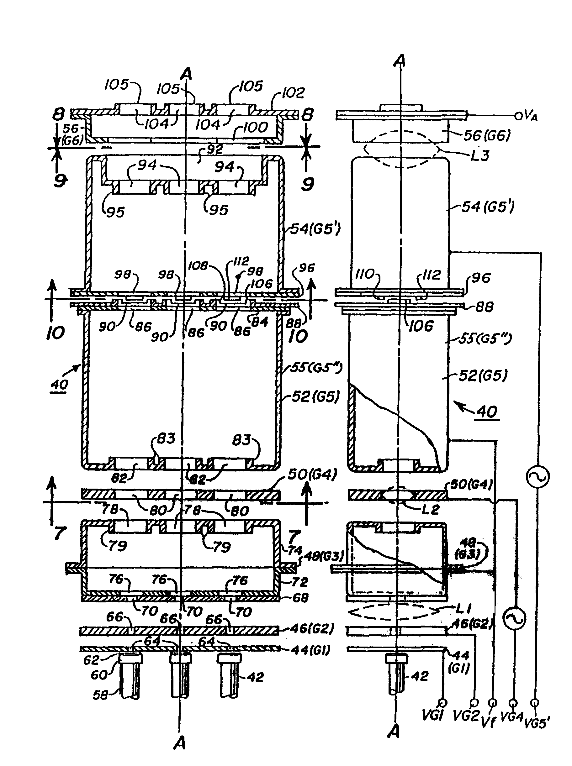
图5和图6分别是本发明的电子枪的轴向正视图和侧视图。5 and 6 are axial front and side views, respectively, of the electron gun of the present invention.
图7(第4页),8(第5页),9(第5页)和10(第6页)分别是图5中所示电子枪沿7-7、8-8、9-9和10-10视向的剖面图。Figure 7 (page 4), 8 (page 5), 9 (page 5) and 10 (page 6) are the electron gun shown in Figure 5 along 7-7, 8-8, 9-9 and 10 Sectional view of -10 viewing direction.
图11(第6页)示出本发明电子枪的电子束离开束形成区(第一透镜)时的束电流密度等值线。Fig. 11 (page 6) shows the beam current density contours of the electron beam of the electron gun of the present invention when it leaves the beam forming region (first lens).
图12(第6页)示出由本发明电子枪的第二透镜产生的电子束在主透镜中的电流密度等值线。Fig. 12 (page 6) shows the current density contours in the main lens of the electron beams generated by the second lens of the electron gun of the present invention.
图13(第7页)示出两条曲线,它们分别表示为了使沿管子长轴和沿荧光屏顶部的电子束的垂直分量聚焦而必须在G5′电 极的7KV聚焦电压上叠加的行频调制电压。Fig. 13 (page 7) shows two curves which represent, respectively, what must be done at the G5' electrode in order to focus the vertical component of the electron beam along the long axis of the tube and along the top of the phosphor screen. The horizontal frequency modulation voltage superimposed on the 7KV focusing voltage of the pole.
图14(第8页)示出一条曲线,它表示为了使沿管子短轴的电子束聚焦而必须在G4电极的最佳低聚焦电压上叠加的帧频调制电压。Figure 14 (page 8) shows a graph representing the frame rate modulation voltage which must be superimposed on the optimum low focusing voltage of the G4 electrode in order to focus the electron beam along the short axis of the tube.
图15(第9页)示出一条曲线,它表示为了把附加的聚焦校正因子应用于偏转电子束而必须在G4电极的最佳低聚焦电压上叠加的行频调制电压。Figure 15 (page 9) shows a graph representing the HFM voltage that must be superimposed on the optimum low focus voltage of the G4 electrode in order to apply an additional focus correction factor to the deflected electron beam.
图16(第10页)示出一对曲线,它们说明荧光屏上沿长轴的3D和9D位置上电子束光点尺寸与加在G4电极上的行频调制电压的函数关系。Figure 16 (page 10) shows a pair of graphs illustrating beam spot size as a function of HFM voltage applied to the G4 electrode for 3D and 9D positions along the major axis of the phosphor screen.
图17(第11页)示出一对曲线,它们说明荧光屏上沿管子短轴的6D和12D位置上的电子束光点尺寸与加在G4电极上的帧频调制电压的函数关系。Figure 17 (page 11) shows a pair of graphs illustrating beam spot size on the phosphor screen at positions 6D and 12D along the minor axis of the tube as a function of the frame rate modulation voltage applied to the G4 electrode.
图1示出普通的矩形彩色显象管10,其玻壳11包括矩形面板12和与矩形玻锥16连接的管状管颈14。面板12包括观看面板18和周围凸缘或侧壁20,用熔接密封方法把凸缘20密封到玻锥16上。在面板18的内表面上设置镶嵌式三色荧光屏。该荧光屏最好是条形屏,同时,荧光条沿着基本上垂直于管子的高频光栅行扫描方向(行扫描方向垂直于图1的平面)延伸。此外,该荧光屏可以是点屏。用普通方法,把多孔选色电极或荫罩板24可拆卸地安装在离开荧光屏22预定距离处。用虚线示意地示于图1中的一字排列式电子枪26安装在管颈14内中央处,用于产生三束电子束28,并使它们沿着初始的共平面束路径穿过荫罩板24射向荧光屏22。普通电子枪之一是四栅极双电位电子枪,例如,
1986年10月28日授予Morrell等人的美国专利4,620,133中所描述、示于本文图2中的电子枪。FIG. 1 shows a conventional rectangular color picture tube 10 whose
图1中的管子预定与外部磁偏转系统配合使用,例如,位于玻锥和管颈连接区的偏转系统30。当激励偏转系统30时,该系统使三束电子束28受到磁场的作用,该磁场使电子束在荧光屏22上的矩形光栅中水平和垂直扫描。图1中用靠近偏转系统30中央的线P-P表示起始偏转(零偏转状态)平面。由于边缘场的缘故,管子的偏转区从偏转系统30沿轴向伸入电子枪26的区域。为了简化,图1中未示出偏转区中偏转电子束路径的实际弯曲情况。偏转系统30产生非均匀磁场,该磁场具有强枕形垂直偏转磁场和强桶形水平偏转磁场,以便在荧光屏22的周围部分使电子束会聚。电子束在穿过这种非均匀磁场时发生畸变和散焦。结果,在荧光屏22的周围部分,电子束光点的形状严重畸变。图3表示单电子束的束光点,该光点在荧光屏的中心处是园的,而在荧光屏的周围产生各种形式的畸变。如图3中所示,当沿着水平轴偏转时,电子束光点在水平方向上拉长了。在荧光屏的四个角落,电子束光点由水平拉长部分和垂直拉长部分组合而成,结果,形成带周围晕圈状拉长部分的椭园形光点。分辨率随着电子束偏转而降低,因而,不可忽略的非均匀聚焦产生了必须予以解决的问题。The tube of Figure 1 is intended for use with an external magnetic deflection yoke, for example,
上述美国专利4,620,133致力于所述束聚焦问题,其方法是:提供一种包括偏转系统和电子枪的彩色图象显示装置,该电子枪具有束形成区(该区包括第一栅极G1,第二栅极G2和第三栅极G3)和主聚焦透镜G3-G4,该主聚焦透镜和偏转系统、束形成区协同工作,以在荧光屏22上形成束光点。本文中的图4a
示出对于由图2中所示电子枪的束形成区和主透镜产生的电子束而言,荧光屏22中心处的电子束电流密度等值线。所述电子枪电流是4毫安。图4a的电子束电流密度等值线包括比较大的中心区和一些周边区,所述中心区具有基本上不变的束电流,其值大约是平均束电流的50%,而在周边区,束电流降到平均束电流的大约5%、最后降到平均束电流的1%。该电子束沿垂直轴拉长成椭园形,以减小电子束偏转系统的过聚焦作用。图4b示出在图2的电极G3和G4之间的主透镜L2中的束电流密度等值线。在该位置,电子束在水平方向上被拉长;但是,50%束电流密度区仍然容纳在电子束的小的椭园形中心部分中,该中心部分的周围是代表电子束的5%和1%电流密度等值线的比较大的椭园区,所述电子束是偏转到荧光屏右上角的电子束。在该电子束中心部分的上、下出现相同的晕圈。在大屏幕电视机和CAD/CAM应用场合,所述普通双电位电子枪在荧光屏上产生的束光点是不能令人满意的。The aforementioned U.S. Patent No. 4,620,133 is devoted to said beam focusing problem by providing a color image display device comprising a deflection yoke and an electron gun having a beam forming region (the region comprising a first grid G1 , the second grid G2 and the third grid G3) and the main focusing lens G3-G4, the main focusing lens cooperates with the deflection yoke and the beam forming area to form a beam spot on the
图4和6中示出本发明电子枪40的细节。电子枪40包括:三个等间距的共平面的阴极42(每束电子束一个阴极),控制栅极44(G1),帘栅极46(G2),第三电极48(G3),第四电极50(G4),第五电极52(G5)(该G5电极包括G5′部分54和G5″部分55)以及第六电极56(G6)。这些电极按名称顺序以阴极为起点隔开排列,并固定在一对玻璃支撑杆(未示出)上。Details of the
阴极42,G1电极44,G2电极46和G3电极48面向G2电极46的那部分,构成电子枪40的束形成区。G3电极48的另一部分,G4电极50和G5电极52的G5″部分55,
构成第一非对称透镜。G5电极52的G5′部分54和G6电极56构成主聚焦透镜(或第二非对称透镜)。The portion of the cathode 42, the G1 electrode 44, the G2 electrode 46 and the G3 electrode 48 facing the G2 electrode 46 constitutes the beam forming region of the
如本领域中众所周知的,每个阴极42包括其前端由阴极帽60封闭的阴极筒58,阴极帽60具有包含电子发射材料的端部涂层62。每个阴极42由位于阴极筒58内适当位置上的热子线圈(未示出)间接加热。As is well known in the art, each cathode 42 includes a cathode can 58 closed at the front end by a cathode cap 60 having an end coating 62 comprising an electron emissive material. Each cathode 42 is heated indirectly by heating sub-coils (not shown) positioned in place within cathode cartridge 58 .
G1和G2电极44、46是两个彼此靠近的、基本上平的平板电极,它们各自具有三个穿过其中的一字排列的小孔64和66。小孔64和66与阴极涂层62对中,以激励射向荧光屏22的三束等间隔的共平面电子束28(如图1中所示)。起始的电子束路径最好是基本上平行的,同时,中间路径与电子枪的中心轴A-A重合。The G1 and G2 electrodes 44, 46 are two adjacent, substantially flat plate electrodes each having three in-line apertures 64 and 66 therethrough. Apertures 64 and 66 are centered with cathode coating 62 to excite three equally spaced coplanar electron beams 28 directed toward phosphor screen 22 (as shown in FIG. 1). The initial electron beam paths are preferably substantially parallel, while the intermediate paths coincide with the central axis A-A of the electron gun.
G3电极48包括基本上平的外平板68,该平板具有穿过其中的三个一字排列的小孔70,这些小孔分别与G2和G1电极中的小孔66和64对中。G3电极48还包括一对杯形的第一和第二部分72和74,这两部分的开口端彼此连接在一起。第一部分72的三个一字排列的小孔76穿过该杯形部分的底部,这三个小孔与平板68中的小孔70对中。G3电极的第二部分74的三个小孔78穿过其底部,这三个小孔与第一部分72中的小孔76对中。小孔78的周围有突起部分79。另一种方法是,平板68及其一字排列的小孔70可以与第一部分72构成整体部件。G3 electrode 48 includes a substantially flat outer plate 68 having three in-line apertures 70 therethrough that are centered with apertures 66 and 64 in the G2 and G1 electrodes, respectively. G3 electrode 48 also includes a pair of cup-shaped first and second portions 72 and 74 connected to each other at their open ends. Three in-line apertures 76 of the first portion 72 pass through the bottom of the cup-shaped portion, the three apertures being aligned with the apertures 70 in the plate 68 . The second portion 74 of the G3 electrode has three apertures 78 passing through its bottom, which are aligned with the apertures 76 in the first portion 72 . The aperture 78 has a raised portion 79 around it. Alternatively, the plate 68 and its inline apertures 70 could be formed as an integral part with the first portion 72 .
新型的G4调制电极50包括基本上平的平板,后者具有穿过其中的三个非旋转对称的一字排列的小孔80,这些小孔与G3电极中的小孔78对中。图7中示出小孔80的形状。The novel
如图7中所示,非旋转对称的小孔80在水平方向(即,各小孔的排列方向)上伸长。小孔80中的每一个包括基本上园的中心部分,后者包括半径r1=0.079英寸(2.007mm)的主孔120和一对反向设置的弧形部分122,后者由位于主孔的每一侧的副孔构成。该副孔与主孔120局部重叠,而每个副孔的半径r2=0.020英寸(0.511mm),并且,每个副孔位于水平轴B-B上、离开主孔120的中心0.067英寸(1.702mm)的距离,因此,小孔80的总的水平尺寸H是0.174英寸(4.420mm)。副孔122平滑地融合在主孔120中。小孔80的最大垂直尺寸是0.158英寸(4.013mm),即,等于主孔120的直径。该园形主孔便于用园柱形装配销钉组装电子枪元件。非旋转对称小孔80提供对穿过其间的电子束的四极聚焦作用,并且,通过在其上加上随电子束偏转而变化的动态电压来加强这种作用。上述美国专利4,319,163公开了在较低电压的电子枪元件上加动态电压的方法。As shown in FIG. 7 , the non-rotationally symmetrical
G5″电极部分55包括第一深拉的杯形构件,在该构件的底部加工三个由突起部分83围绕的小孔82。基本上平的平板构件84(该构件的三个小孔86与小孔82对中)固定在第一杯形构件的开口端,并且,将该开口端封闭。有多个小孔90的第一平板部分88固定在平板构件84的反面。The G5" electrode portion 55 comprises a first deep-drawn cup-shaped member at the bottom of which is machined three apertures 82 surrounded by protruding portions 83. A substantially flat plate member 84 (the three apertures 86 of which are in contact with Aperture 82 centering) is fixed on the open end of the first cup-shaped member, and, this open end is closed.The first plate part 88 that has a plurality of apertures 90 is fixed on the opposite side of plate member 84.
G5′电极部分54包括第二深拉杯形构件,在该构件的底部形成凹槽92,同时,在凹槽92的底面加工三个一字排列的小孔94。突起部分95围绕小孔94。G5′电极部分54的反向开口端由第二平板部分96封闭,穿过该第二平板部分的三个小孔与
第一平板部分88中的小孔90对中,并且,按下述方式与小孔90相配合。The G5'
G6电极56是杯形的深拉构件,该构件具有在其一端的大孔100(三束电子束都穿过该大孔)和一个开口端,平板构件102固定在该开口端,并且,将该开口端封闭,穿过该平板构件的三个小孔104与G5′电极部分54中的小孔94对中。突起部分105围绕小孔104。The
图8中示出G5′电极部分54中的凹槽92的形状。对于每个电子束路径来说,凹槽92具有一致的垂直高度,该凹槽具有园形的端部。该形状称为“跑道”形。The shape of the
图9中示出G6电极56中大孔100的形状。大孔100的垂直高度在边侧电子束路径处较大,而在中心电子束路径处较小。该形状称为“狗骨”或杆铃”形。The shape of the
G5″电极部分55的第一平板部分88面对G5′电极部分54的第二平板部分96。第一平板部分88中的小孔90具有从该平板部分伸出的突起部分,对于每个小孔,该突起部分分成两个分段106和108。第二平板部分中的小孔98也具有从该平板部分伸出的突出部分,对于每个小孔,该突起部分分成两个分段110和112。如图10中所示,分段106和108与分段110和112相交错。这些分段用于当把不同电压分别加到G5″电极部分55和G5′电极部分54时,在每个电子束路径中建立多极(例如,四极)透镜。通过在G5′电极上加上适当的动态电压信号,有可能利用由分段106、108、110和112建立的四极透镜,提供对电子束的象散校正,以校正或者在电子枪中、
或者在偏转系统中出现的象散。上述美国专利4,731,563描述了这种四极透镜。The first plate portion 88 of the G5" electrode portion 55 faces the
下表中给出用于27V110管子中的用计算机模拟的电子枪的具体尺寸。The specific dimensions of the computer modeled electron gun used in the 27V110 tube are given in the table below.
表surface
英寸 毫米inches mm
K-G1间隔。 0.003 0.08K-G1 interval. 0.003 0.08
G1电极44的厚度 0.0025 0.06The thickness of G1 electrode 44 0.0025 0.06
G2电极46的厚度 0.024 0.61The thickness of G2 electrode 46 0.024 0.61
G1和G2小孔直径 0.025 0.64G1 and G2 hole diameter 0.025 0.64
G1与G2间隔 0.010 0.25G1 and G2 interval 0.010 0.25
G2与G3间隔 0.03 0.76G2 and G3 interval 0.03 0.76
G3平板部分68的厚度 0.010 0.25Thickness of G3 flat part 68 0.010 0.25
G3小孔直径 0.040 1.02G3 hole diameter 0.040 1.02
G3电极长度 0.200 5.08G3 electrode length 0.200 5.08
G4电极50的厚度 0.035 0.89The thickness of
G4电极小孔尺寸 0.158V X 4.01V XG4 electrode hole size 0.158V X 4.01V X
0.174H 4.42H0.174H 4.42H
G3与G4间隔 0.050 1.27Interval between G3 and G4 0.050 1.27
G5″和G5′电极部分G5″ and G5′ Electrode Parts
55和54的总长度 0.890 22.61Total length of 55 and 54 0.890 22.61
G4和G5间隔 0.050 1.27G4 and G5 interval 0.050 1.27
平板部份88与96之间间隔 0.040 1.02The distance between the
(续表)(Continued)
凹槽92长度 0.715 18.16
凹槽92垂直高度 0.315 8.00
凹槽92深度 0.115 2.92
G6电极的长度 0.130 3.30Length of G6 electrode 0.130 3.30
G5与G6间隔 0.050 1.27Interval between G5 and G6 0.050 1.27
小孔78,82,90,94,98 0.160 4.06
和104的直径and a diameter of 104
中心至中心的小孔间隔 0.200 5.08Hole spacing center to center 0.200 5.08
大孔100长度 0.698 17.73
大孔100在中央电子束处的垂直高度 0.267 6.78The vertical height of the
大孔100在边侧电子束处的垂直高度 0.280 7.11The vertical height of the
大孔100深度 0.115 2.92
G3突起部份79的长度 0.035 0.89Length of G3 protrusion 79 0.035 0.89
G5突起部份83的长度 0.029 0.74Length of G5 protrusion 83 0.029 0.74
G5′突起部份95的长度 0.034 0.86The length of G5' protruding part 95 0.034 0.86
G6突起部份105的长度 0.045 1.14Length of G6 protruding part 105 0.045 1.14
在表中给出的实施例中,电子枪40象图6中所示那样电连接。一般说来,阴极工作在大约150V,G1电极处在地电位,G2电极工作在大约300V至1000V的范围内,G3电极和G5″电极部分互相连接并工作在大约7KV,而G6电极工作在大约25KV的阳极电压。至少在G4电极和G5′电极上
加上不同的动态电压。In the examples given in the table, the
在本发明的电子枪40中,第一透镜L1(图6)包括G1电极44,G2电极46和G3电极48的相邻部分,透镜L1形成对称形的高质量电子束,而不是第二透镜L2中的非对称形电子束。图11中示出L1的各电子束之一的束电流密度等值线。可以看出,本发明的束形成区不在电子束中产生任何明显的不对称性。In the
第二透镜L2包括G4调制电极50和G3电极48及G5电极52的相邻部分(即,G5″电极部分55),透镜L2构成非对称透镜,后者形成水平方向拉长的电子束,图12中示出该电子束在第三透镜(即,主透镜)L3中的束光点等值线。穿过G4电极50的非旋转对称小孔80和加到其上的动态电压相结合,产生基本上椭园形的电子束。The second lens L2 includes the
在G5′电极部分54和G6电极56之间形成的主聚焦透镜(即,第三透镜)L3还是低象差透镜;当主透镜调制电极部分54与聚焦电极52处于相同电位(大约7KV)、并且、G4电极50与G2电极46处于相同电位(大约350V)时,该透镜处于最佳状态(如下所述,在荧光屏中央获得零象散)。The main focusing lens (i.e., the third lens) L3 formed between the G5'
在本发明的电子枪40中,G4调制电极50对于沿管子长轴(一字排列式电子枪的排列方向)从3D至9D的荧光屏位置的行频调制(15.75KHZ)和沿管子短轴(垂直于所述排列方向)从6D至12D的荧光屏位置的帧频调制(60H)都有影响。但是,由于在大电流情况下G4电极太靠近电子束交叉位置,所以,
该电极不能完全补偿在管子角落2D、10D(由于对称性,也不能完全补偿在管子角落4D、8D)中的偏转散焦。由于在帧扫描频率下在高电压聚焦电源(7KV)中电容耦合的困难,以及,由于仅仅利用低电压的G4电极50、在管子的角落(2D、10D和4D、8D)行频调制无效,所以,本发明采用双调制电极。行频调制是通过把基本上抛物线形的电压信号(该电压随偏转角的增大而增加)叠加到聚焦电源电压(该电压加到G5′电极部分54)上来完成的。帧频调制是通过把不同的抛物线形电压信号(该信号也随偏转角的增大而增加)加到低聚焦电压(该电压加到G4电极50)上来实现的。In the
图13示出第一曲线124,该曲线描述为了聚焦沿管子长轴从位置3D至位置9D的电子束、在G5′电极部分54上所需要的行频调制电压信号〔相对于(荧光屏中心)聚焦电压(7KV)而言〕。曲线126表示:当把适当的帧频调制电压信号加到G4电极50、以便沿管子的短轴从位置6D至位置12D校正电子束聚焦时,在G5′电极部分54上需要较高的行频调制电压、以便从荧光屏顶部(或底部)的这头到那头(从2D至10D,或者,4D至8D)聚焦电子束。图14中示出帧频调制电压信号曲线128。Figure 13 shows a first curve 124 which describes the horizontal frequency modulation voltage signal required on the G5'
从图13可以看出,由图13和14的波形所提供的双电极动态调制信号电压的缺点在于:为了沿荧光屏的顶部、在角落2D和10D处正确地聚焦电子束所需的行频调制电压信号(曲
线126),大于沿管子的长轴、从3D至9D正确地聚焦电子束所需的行频调制电压信号(曲线124)。换句话说,用G5′主透镜电极部分54的行频调制和G4电极50的帧频调制,不能完全实现沿长/短轴和在所述各角落位置上同时聚焦电子束。虽然,所述“简单”的双电极动态调制是适当的,但是,它未能使该装置的性能最佳化。As can be seen from Fig. 13, the disadvantage of the two-electrode dynamically modulated signal voltage provided by the waveforms of Figs. voltage signal (qu
Line 126), which is greater than the HFM voltage signal (curve 124) required to properly focus the electron beam from 3D to 9D along the long axis of the tube. In other words, with the horizontal frequency modulation of the G5' main
采用“复合”双栅极调制能使该系统的性能最佳化,所述调制迫使沿长轴(3D至9D)和在各角落(2D至10D)的总的行频调制电压相等。因为,虽然对于荧光位置3D和9D处的行频调制来说G4电极50是有效的、但这对于角落2D和10D无效,所以,通过在G4调制电极50上加上附加的行频调制电压信号,能够实现上述目的。因此,通过把在10至-300V(相对于G2)范围内的第二行频调制电压信号130加到G4电极50上、使3D和9D位置上的电子束过聚焦,能够把加到G5′电极部分54上的第一行频调制电压信号的幅度提高到曲线126中所示的值,从而,在保持沿长轴在3D和9D位置上聚焦的同时,在角落2D和10D处实现聚焦。图15示出第二行频调制电压信号130。The performance of this system can be optimized using a "composite" dual gate modulation that forces the total horizontal frequency modulation voltage to be equal along the long axis (3D to 9D) and at the corners (2D to 10D). Because, although the
图16和17分别表示加到G4电极50上的行频和帧频调制电压信号对沿长轴在3D至9D处以及沿短轴在6D至12D处的束光点尺寸的影响。图16表示:在比350V的G2电压低大约300V的所需要的工作点的情况下,沿着管子的长轴,荧光屏上的电子束光点尺寸在水平方向上以大约1.6∶1的比例拉长。图17表示:在比G2电压高大约300V的所需要的工作点的情况下,在沿管子短轴的位置6D和12D处,荧光屏上电子束光点尺
寸在垂直方向上以大约1.7∶1的比例拉长。上述调制影响垂直方向的光点尺寸、而基本上不影响水平方向的光点尺寸。Figures 16 and 17 respectively show the effect of horizontal rate and frame rate modulation voltage signals applied to the
总之,改进的电子枪40包括三个透镜,可以分别调制其中的第二和第三透镜,以校正由在管壳的玻锥和管颈连接处围绕管子的自会聚偏转系统在电子枪中引起的象差。第三透镜包括G5′电极部分,可以用具有行扫描频率的第一电压信号调制该电极,以便沿着管子长轴的方向,为荧光屏上的电子束提供聚焦校正。可以把具有帧扫描频率的第二电压信号加到第二透镜的G4电极上,以便沿着管子的短轴方向,为荧光屏上的电子束提供聚焦校正。通过采用复合双调制技术(该技术除了上述调制电压之外,还包括加到G4电极上的附加行频调制电压信号)以及提高加到G5′电极部分上的行频调制电压,不但能沿着长轴和短轴使电子束的聚焦最佳化,而且,能在荧光屏的各角落上使电子束聚焦。In summary, the
Claims (2)
Priority Applications (1)
| Application Number | Priority Date | Filing Date | Title |
|---|---|---|---|
| CN 91110595 CN1023674C (en) | 1988-10-27 | 1991-11-02 | Color cathode ray tube having a dual electrode modulated electron gun |
Applications Claiming Priority (2)
| Application Number | Priority Date | Filing Date | Title |
|---|---|---|---|
| US07/263,454 US4877998A (en) | 1988-10-27 | 1988-10-27 | Color display system having an electron gun with dual electrode modulation |
| US263,454 | 1988-10-27 |
Related Child Applications (1)
| Application Number | Title | Priority Date | Filing Date |
|---|---|---|---|
| CN 91110595 Division CN1023674C (en) | 1988-10-27 | 1991-11-02 | Color cathode ray tube having a dual electrode modulated electron gun |
Publications (2)
| Publication Number | Publication Date |
|---|---|
| CN1042270A CN1042270A (en) | 1990-05-16 |
| CN1017204B true CN1017204B (en) | 1992-06-24 |
Family
ID=23001847
Family Applications (1)
| Application Number | Title | Priority Date | Filing Date |
|---|---|---|---|
| CN89107897A Expired CN1017204B (en) | 1988-10-27 | 1989-10-10 | Color display system with double-electrode modulated electron gun |
Country Status (10)
| Country | Link |
|---|---|
| US (1) | US4877998A (en) |
| EP (1) | EP0366245B1 (en) |
| JP (1) | JPH0795429B2 (en) |
| KR (1) | KR0121798B1 (en) |
| CN (1) | CN1017204B (en) |
| CA (1) | CA1317033C (en) |
| DD (1) | DD288266A5 (en) |
| DE (1) | DE68919803T2 (en) |
| PL (1) | PL162108B1 (en) |
| RU (1) | RU2030808C1 (en) |
Families Citing this family (33)
| Publication number | Priority date | Publication date | Assignee | Title |
|---|---|---|---|---|
| US5262702A (en) * | 1989-03-23 | 1993-11-16 | Kabushiki Kaisha Toshiba | Color cathode-ray tube apparatus |
| US5036258A (en) * | 1989-08-11 | 1991-07-30 | Zenith Electronics Corporation | Color CRT system and process with dynamic quadrupole lens structure |
| JPH088078B2 (en) * | 1989-10-16 | 1996-01-29 | 松下電子工業株式会社 | Color picture tube device |
| DE69025126T2 (en) * | 1989-11-09 | 1996-06-05 | Toshiba Kawasaki Kk | Color cathode ray tube and its control method |
| KR970008564B1 (en) * | 1989-11-21 | 1997-05-27 | 엘지전자 주식회사 | Electron gun for color cathode ray tube |
| JP3053827B2 (en) * | 1990-02-08 | 2000-06-19 | 株式会社日立製作所 | Electron gun and cathode ray tube |
| US5066887A (en) * | 1990-02-22 | 1991-11-19 | Rca Thomson Licensing Corp. | Color picture tube having an inline electron gun with an astigmatic prefocusing lens |
| US5202604A (en) * | 1990-05-08 | 1993-04-13 | Samsung Electron Devices Co., Ltd. | Electron gun for cathode ray tube |
| US4990832A (en) * | 1990-05-22 | 1991-02-05 | Rca Licensing Corporation | Color display system |
| JP3053845B2 (en) * | 1990-06-07 | 2000-06-19 | 株式会社日立製作所 | Cathode ray tube |
| GB9104649D0 (en) * | 1991-03-05 | 1991-04-17 | Secr Defence | Focusing means for cathode ray tubes |
| DE69209125T2 (en) * | 1991-04-17 | 1996-10-02 | Philips Electronics Nv | Display device and cathode ray tube |
| FR2682809B1 (en) * | 1991-10-21 | 1993-12-31 | Thomson Tubes Displays Sa | CATHODE RAY TUBE WITH IMPROVED ELECTRON CANON. |
| JP3339059B2 (en) * | 1991-11-14 | 2002-10-28 | ソニー株式会社 | Cathode ray tube |
| FR2705164B1 (en) * | 1993-05-10 | 1995-07-13 | Thomson Tubes & Displays | Color image tube with electron guns in line with astigmatic lenses. |
| JPH0721936A (en) | 1993-06-30 | 1995-01-24 | Hitachi Ltd | Cathode ray tube |
| JPH07134953A (en) * | 1993-11-09 | 1995-05-23 | Hitachi Ltd | Color picture tube |
| KR970001591B1 (en) * | 1993-11-30 | 1997-02-11 | 오리온전기 주식회사 | Electron gun for colored cathode ray tube |
| KR950020923A (en) * | 1993-12-07 | 1995-07-26 | 이헌조 | Color tube gun |
| JPH07161308A (en) * | 1993-12-07 | 1995-06-23 | Hitachi Ltd | Electron gun for color cathode ray tube |
| EP0716771B1 (en) * | 1994-05-06 | 1998-07-08 | Koninklijke Philips Electronics N.V. | Display device and cathode ray tube |
| KR100192456B1 (en) * | 1994-08-13 | 1999-06-15 | 구자홍 | Electron muzzle for color water pipe |
| US6057013A (en) * | 1996-03-07 | 2000-05-02 | Chevron Chemical Company | Oxygen scavenging system including a by-product neutralizing material |
| KR100186540B1 (en) | 1996-04-25 | 1999-03-20 | 구자홍 | Electrode of pdp and its forming method |
| JP3726402B2 (en) * | 1996-07-05 | 2005-12-14 | ソニー株式会社 | In-line electron gun for color cathode ray tube |
| CN1134040C (en) * | 1996-11-04 | 2004-01-07 | 皇家菲利浦电子有限公司 | Color cathode ray tube comprising in-line electron gun |
| TW402732B (en) * | 1998-06-09 | 2000-08-21 | Koninkl Philips Electronics Nv | Cathode ray tube comprising an electron gun |
| FR2810488B1 (en) * | 2000-06-16 | 2002-08-30 | St Microelectronics Sa | CORRECTION OF CONVERGENCE OF A CATHODIC TUBE SCREEN OR PROJECTOR |
| KR100357172B1 (en) * | 2000-12-23 | 2002-10-19 | 엘지전자주식회사 | Electron Gun for Color Cathode Ray Tube |
| KR100719533B1 (en) * | 2001-05-04 | 2007-05-17 | 삼성에스디아이 주식회사 | Electron gun for colored cathode ray tube |
| KR20020085463A (en) * | 2001-05-08 | 2002-11-16 | 삼성에스디아이 주식회사 | Electron gun for beam index type cathode ray tube |
| JP5426827B2 (en) * | 2004-05-03 | 2014-02-26 | ドルビー ラボラトリーズ ライセンシング コーポレイション | Method, program, system, apparatus, and display for processing a series of frames for display on a display |
| CN109211101B (en) * | 2018-10-11 | 2023-09-22 | 中国科学院电工研究所 | Electron beam centering detection tube and electron beam centering detection device |
Family Cites Families (12)
| Publication number | Priority date | Publication date | Assignee | Title |
|---|---|---|---|---|
| JPS5715463B2 (en) * | 1973-11-13 | 1982-03-30 | ||
| US3952224A (en) * | 1974-10-04 | 1976-04-20 | Rca Corporation | In-line electron guns having consecutive grids with aligned vertical, substantially elliptical apertures |
| US3984723A (en) * | 1974-10-04 | 1976-10-05 | Rca Corporation | Display system utilizing beam shape correction |
| US4234814A (en) * | 1978-09-25 | 1980-11-18 | Rca Corporation | Electron gun with astigmatic flare-reducing beam forming region |
| US4319163A (en) * | 1980-06-30 | 1982-03-09 | Rca Corporation | Electron gun with deflection-synchronized astigmatic screen grid means |
| US4620133A (en) * | 1982-01-29 | 1986-10-28 | Rca Corporation | Color image display systems |
| JPS6199249A (en) * | 1984-10-18 | 1986-05-17 | Matsushita Electronics Corp | Picture tube apparatus |
| NL8600117A (en) * | 1986-01-21 | 1987-08-17 | Philips Nv | COLOR IMAGE TUBE WITH REDUCED DEFLECTION DEFOCUSING. |
| US4731563A (en) * | 1986-09-29 | 1988-03-15 | Rca Corporation | Color display system |
| JP2569027B2 (en) * | 1986-12-05 | 1997-01-08 | 株式会社日立製作所 | Electron gun for color picture tube |
| DE3854506T2 (en) * | 1987-01-14 | 1996-04-04 | Rca Thomson Licensing Corp | Color picture tube with a three-lens electron gun. |
| US4764704A (en) * | 1987-01-14 | 1988-08-16 | Rca Licensing Corporation | Color cathode-ray tube having a three-lens electron gun |
-
1988
- 1988-10-27 US US07/263,454 patent/US4877998A/en not_active Expired - Lifetime
-
1989
- 1989-09-08 DD DD89332483A patent/DD288266A5/en not_active IP Right Cessation
- 1989-09-08 EP EP89309148A patent/EP0366245B1/en not_active Expired - Lifetime
- 1989-09-08 DE DE68919803T patent/DE68919803T2/en not_active Expired - Lifetime
- 1989-09-14 CA CA000611427A patent/CA1317033C/en not_active Expired - Fee Related
- 1989-09-22 JP JP1247862A patent/JPH0795429B2/en not_active Expired - Lifetime
- 1989-09-22 PL PL89281553A patent/PL162108B1/en unknown
- 1989-10-03 RU SU4614989/21A patent/RU2030808C1/en not_active IP Right Cessation
- 1989-10-10 CN CN89107897A patent/CN1017204B/en not_active Expired
- 1989-10-24 KR KR1019890015364A patent/KR0121798B1/en not_active Expired - Fee Related
Also Published As
| Publication number | Publication date |
|---|---|
| DD288266A5 (en) | 1991-03-21 |
| US4877998A (en) | 1989-10-31 |
| KR0121798B1 (en) | 1997-11-15 |
| PL162108B1 (en) | 1993-08-31 |
| JPH02127887A (en) | 1990-05-16 |
| KR900007037A (en) | 1990-05-09 |
| JPH0795429B2 (en) | 1995-10-11 |
| CA1317033C (en) | 1993-04-27 |
| DE68919803T2 (en) | 1995-06-08 |
| EP0366245B1 (en) | 1994-12-07 |
| CN1042270A (en) | 1990-05-16 |
| EP0366245A2 (en) | 1990-05-02 |
| RU2030808C1 (en) | 1995-03-10 |
| EP0366245A3 (en) | 1990-10-17 |
| DE68919803D1 (en) | 1995-01-19 |
Similar Documents
| Publication | Publication Date | Title |
|---|---|---|
| EP0366245B1 (en) | Color display system and tube having an electron gun with dual electrode modulation | |
| CN1113385C (en) | Cathode ray tube with low dynamic correction voltage | |
| CN1134814C (en) | Color Cathode Ray Tube with Low Dynamic Focus Voltage | |
| JPH04218245A (en) | Color cathode-ray tube | |
| JP2711553B2 (en) | Color display tube and electron gun used therefor | |
| CN87100841A (en) | Improved color display system | |
| CN1018107B (en) | Electron gun of picture tube | |
| JP2000048737A (en) | Color cathode ray tube device | |
| EP0178857A2 (en) | Electron gun | |
| US5763993A (en) | Focusing electrode structure for a color cathode ray tube | |
| US6927531B2 (en) | Electron gun and color picture tube apparatus that attain a high degree of resolution over the entire screen | |
| EP0388901B1 (en) | Color cathode-ray tube apparatus | |
| EP0275191B1 (en) | Color cathode-ray tube having a three-lens electron gun | |
| CN1084927C (en) | Electronic gun for color cathode ray tube | |
| CN1359134A (en) | Crt | |
| US6586868B1 (en) | Color cathode-ray tube apparatus with multi-lens electron focusing and yoke deflection | |
| US6646370B2 (en) | Cathode-ray tube apparatus | |
| JP3053850B2 (en) | Color picture tube equipment | |
| CN1023674C (en) | Color cathode ray tube having a dual electrode modulated electron gun | |
| JPH07211251A (en) | Method for correcting deflection aberration of cathode ray tube, cathode ray tube, and image display device | |
| JP3640694B2 (en) | Color picture tube | |
| KR20020073595A (en) | Display device and cathode ray tube | |
| US7122977B2 (en) | Cathode-ray tube apparatus | |
| EP0427235B1 (en) | Color cathode ray tube apparatus and method for driving the same | |
| US20050057196A1 (en) | Cathode-ray tube apparatus |
Legal Events
| Date | Code | Title | Description |
|---|---|---|---|
| C06 | Publication | ||
| PB01 | Publication | ||
| SE01 | Entry into force of request for substantive examination | ||
| C13 | Decision | ||
| GR02 | Examined patent application | ||
| C14 | Grant of patent or utility model | ||
| GR01 | Patent grant | ||
| C15 | Extension of patent right duration from 15 to 20 years for appl. with date before 31.12.1992 and still valid on 11.12.2001 (patent law change 1993) | ||
| OR01 | Other related matters | ||
| C17 | Cessation of patent right | ||
| CX01 | Expiry of patent term |
Granted publication date: 19930331 |