CN101728687B - Electrical connector - Google Patents
Electrical connector Download PDFInfo
- Publication number
- CN101728687B CN101728687B CN2009102080739A CN200910208073A CN101728687B CN 101728687 B CN101728687 B CN 101728687B CN 2009102080739 A CN2009102080739 A CN 2009102080739A CN 200910208073 A CN200910208073 A CN 200910208073A CN 101728687 B CN101728687 B CN 101728687B
- Authority
- CN
- China
- Prior art keywords
- terminal
- fastener
- towards
- vertical wall
- lance
- Prior art date
- Legal status (The legal status is an assumption and is not a legal conclusion. Google has not performed a legal analysis and makes no representation as to the accuracy of the status listed.)
- Active
Links
Images


Classifications
-
- H—ELECTRICITY
- H01—ELECTRIC ELEMENTS
- H01R—ELECTRICALLY-CONDUCTIVE CONNECTIONS; STRUCTURAL ASSOCIATIONS OF A PLURALITY OF MUTUALLY-INSULATED ELECTRICAL CONNECTING ELEMENTS; COUPLING DEVICES; CURRENT COLLECTORS
- H01R13/00—Details of coupling devices of the kinds covered by groups H01R12/70 or H01R24/00 - H01R33/00
- H01R13/40—Securing contact members in or to a base or case; Insulating of contact members
- H01R13/42—Securing in a demountable manner
- H01R13/422—Securing in resilient one-piece base or case, e.g. by friction; One-piece base or case formed with resilient locking means
- H01R13/4223—Securing in resilient one-piece base or case, e.g. by friction; One-piece base or case formed with resilient locking means comprising integral flexible contact retaining fingers
-
- H—ELECTRICITY
- H01—ELECTRIC ELEMENTS
- H01R—ELECTRICALLY-CONDUCTIVE CONNECTIONS; STRUCTURAL ASSOCIATIONS OF A PLURALITY OF MUTUALLY-INSULATED ELECTRICAL CONNECTING ELEMENTS; COUPLING DEVICES; CURRENT COLLECTORS
- H01R13/00—Details of coupling devices of the kinds covered by groups H01R12/70 or H01R24/00 - H01R33/00
- H01R13/62—Means for facilitating engagement or disengagement of coupling parts or for holding them in engagement
- H01R13/629—Additional means for facilitating engagement or disengagement of coupling parts, e.g. aligning or guiding means, levers, gas pressure electrical locking indicators, manufacturing tolerances
-
- H—ELECTRICITY
- H01—ELECTRIC ELEMENTS
- H01R—ELECTRICALLY-CONDUCTIVE CONNECTIONS; STRUCTURAL ASSOCIATIONS OF A PLURALITY OF MUTUALLY-INSULATED ELECTRICAL CONNECTING ELEMENTS; COUPLING DEVICES; CURRENT COLLECTORS
- H01R13/00—Details of coupling devices of the kinds covered by groups H01R12/70 or H01R24/00 - H01R33/00
- H01R13/02—Contact members
- H01R13/10—Sockets for co-operation with pins or blades
- H01R13/11—Resilient sockets
- H01R13/113—Resilient sockets co-operating with pins or blades having a rectangular transverse section
-
- H—ELECTRICITY
- H01—ELECTRIC ELEMENTS
- H01R—ELECTRICALLY-CONDUCTIVE CONNECTIONS; STRUCTURAL ASSOCIATIONS OF A PLURALITY OF MUTUALLY-INSULATED ELECTRICAL CONNECTING ELEMENTS; COUPLING DEVICES; CURRENT COLLECTORS
- H01R13/00—Details of coupling devices of the kinds covered by groups H01R12/70 or H01R24/00 - H01R33/00
- H01R13/40—Securing contact members in or to a base or case; Insulating of contact members
- H01R13/42—Securing in a demountable manner
- H01R13/436—Securing a plurality of contact members by one locking piece or operation
- H01R13/4364—Insertion of locking piece from the front
-
- H—ELECTRICITY
- H01—ELECTRIC ELEMENTS
- H01R—ELECTRICALLY-CONDUCTIVE CONNECTIONS; STRUCTURAL ASSOCIATIONS OF A PLURALITY OF MUTUALLY-INSULATED ELECTRICAL CONNECTING ELEMENTS; COUPLING DEVICES; CURRENT COLLECTORS
- H01R13/00—Details of coupling devices of the kinds covered by groups H01R12/70 or H01R24/00 - H01R33/00
- H01R13/62—Means for facilitating engagement or disengagement of coupling parts or for holding them in engagement
- H01R13/639—Additional means for holding or locking coupling parts together, after engagement, e.g. separate keylock, retainer strap
-
- H—ELECTRICITY
- H01—ELECTRIC ELEMENTS
- H01R—ELECTRICALLY-CONDUCTIVE CONNECTIONS; STRUCTURAL ASSOCIATIONS OF A PLURALITY OF MUTUALLY-INSULATED ELECTRICAL CONNECTING ELEMENTS; COUPLING DEVICES; CURRENT COLLECTORS
- H01R13/00—Details of coupling devices of the kinds covered by groups H01R12/70 or H01R24/00 - H01R33/00
- H01R13/64—Means for preventing incorrect coupling
Landscapes
- Connector Housings Or Holding Contact Members (AREA)
Abstract
一种具备端子的电连接器及该端子。矛形部具有:在端子插入过程被端子的卡止部按压而一边朝外侧弹性位移一边使卡止部可通过地引导的引导面;在端子插入结束时解除弹性位移、与卡止部相面对的卡止前端面;与对方连接器的壳体相面对的方式形成于矛形部的外面的被限制面,端子在接触部与连结部之间具有弯曲部,卡止部从成为弯曲部的侧壁的竖立壁的上缘延伸,其特征为,端子除了卡止部外还具有限制部,卡止部与限制部是从弯曲部两侧的竖立壁中一方的竖立壁朝另一方的竖立壁延伸形成,限制部具有当端子插入结束时与矛形部的内面相对面的限制面。本发明能够防止矛形部的折曲。
An electric connector with a terminal and the terminal. The spear-shaped portion has: a guide surface that is pressed by the locking portion of the terminal during the terminal insertion process and elastically displaces outward while allowing the locking portion to pass through; when the terminal insertion is completed, the elastic displacement is released and faces the locking portion. The locking front end face of the pair; the restricted surface formed on the outer surface of the lance-shaped part in a way to face the housing of the opposite connector, the terminal has a curved part between the contact part and the connecting part, and the locking part becomes curved from The upper edge of the upright wall of the side wall of the bending part extends, and it is characterized in that the terminal also has a restricting part in addition to the locking part. The upstanding wall is formed by extension, and the restricting portion has a restricting surface opposite to the inner surface of the lance when the terminal insertion is completed. The present invention can prevent bending of the lance.
Description
技术领域 technical field
本发明是涉及电连接器及该连接器用的端子,特别是涉及在壳体的端子孔处设有矛形部而在端子处设有与该矛形部卡止的卡止部的电连接器及端子。The present invention relates to an electrical connector and a terminal for the connector, in particular to an electrical connector in which a lance is provided at the terminal hole of the housing and a locking portion is provided at the terminal to lock with the lance. and terminals.
背景技术 Background technique
作为该电连接器,专利文献1所揭示的电连接器(以下称为“连接器”)为众所皆知。此专利文献1的连接器在电缆被连结于端子的后部的状态下,从前部的接触部插入到壳体的端子孔。端子具有防止脱离用的卡止部,该卡止部与设置在壳体的矛形部的前端面卡止。该矛形部呈脚状并具有弹性,在端子插入过程中被所述卡止部按压而弹性位移,使该卡止部可通过矛形部的位置。当端子插入结束时,所述弹性位移被解除,所述卡止部与所述矛形部的前端面卡止。As such an electrical connector, an electrical connector disclosed in Patent Document 1 (hereinafter referred to as a "connector") is known. The connector of
在端子插入结束后,箱状的按键构件嵌合固定于壳体上,该按键构件的一部分会与所述矛形部的外侧面接近并与之相面对,成为不可朝矛形部的外侧弹性位移,即使端子在电缆上受到不经意的拔出力,卡止部也能维持与所述矛形部的卡止。After the terminal insertion is completed, the box-shaped button member is fitted and fixed on the housing, and a part of the button member will be close to and face the outer surface of the lance-shaped portion, so that it cannot move toward the outer side of the lance-shaped portion. Elastic displacement, even if the terminal receives inadvertent pull-out force on the cable, the locking part can maintain locking with the spear-shaped part.
[专利文献1]日本特开2004-281207[Patent Document 1] Japanese Patent Laid-Open No. 2004-281207
在专利文献1的连接器上,当连结于端子的电缆被不经意地朝端子拔出方向即朝后方拉引时,端子的卡止部会与脚状的矛形部的前端面抵接,防止端子脱离。当该电缆的拉引力大时,该拉引力会经由卡止部作用于所述矛形部的前端面,因此在呈脚状的矛形部的长轴方向上会产生大的压缩应力,显示出向直角方向折曲的倾向。在专利文献1中,因箱状的按键构件与矛形部的外侧面接近并与之相面对,所以,矛形部朝外侧的位移被所述按键构件所限制,朝外侧的折曲被事先防止。In the connector of
但是,根据作用于电缆的力无法得知所述矛形部的折曲是欲朝内侧还是朝外侧。因此,专利文献1的连接器对朝内侧的折曲无任何对应方法。However, it cannot be known from the force acting on the cable whether the lance is intended to bend inwardly or outwardly. Therefore, the connector of
发明内容 Contents of the invention
本发明是有鉴于这种事情而开发完成的发明,其目的在于提供一种具备端子的电连接器及端子,该端子能够在不会造成构造复杂化的前提下,仅通过加工金属板即可限制矛形部朝内侧的位移,并可防止矛形部折曲。The present invention has been developed in consideration of such a situation, and an object of the present invention is to provide an electrical connector and a terminal provided with a terminal that can be processed only by processing a metal plate without complicating the structure. The inner displacement of the lance is limited, and the lance is prevented from being bent.
本发明的电连接器的向着前方朝形成于壳体上的端子孔插入的金属板制的端子具有:用来与对方端子接触的接触部、用来与电缆连结的连结部、以及当端子的插入结束时与在所述端子孔的内壁的一部分形成的矛形部卡止的卡止部,In the electric connector of the present invention, the terminal made of metal plate which is inserted into the terminal hole formed on the housing toward the front has: a contact part for contacting with the opposite terminal, a connecting part for connecting with a cable, and a terminal for use as a terminal. a locking portion that locks with a lance formed on a part of the inner wall of the terminal hole when the insertion is completed,
该矛形部呈朝前方延伸并可朝外侧弹性位移的脚状,The spear-shaped portion is in the shape of a foot extending forward and elastically displacing outward.
该矛形部具有:朝着端子孔的前方而向内侧倾斜地形成于该矛形部的内面上、在端子插入过程中被所述卡止部所按压而一边朝外侧弹性位移一边引导该卡止部、使该卡止中可通过的引导面;当端子插入结束时解除所述弹性位移、从后方与卡止部相面对的卡止前端面;以及以在与对方连接器嵌合的嵌合状态下与该对方连接器的壳体相面对的方式形成于该矛形部的外面的被限制面,The lance portion is formed on the inner surface of the lance portion obliquely inward toward the front of the terminal hole, and is pressed by the locking portion during terminal insertion to guide the card while elastically displacing outward. A stopper, a guide surface that can pass through the lock; when the terminal insertion is completed, the elastic displacement is released, and the front end face of the lock that faces the lock part from the rear; a restricted surface formed on the outer surface of the lance portion so as to face the housing of the mating connector in the mated state,
端子在接触部与连结部之间具有弯曲部,The terminal has a bent portion between the contact portion and the connecting portion,
所述卡止部从成为该弯曲部的侧壁的竖立壁的上缘延伸形成。The locking portion is formed extending from the upper edge of the upstanding wall serving as the side wall of the bent portion.
本发明的端子除了所述卡止部外,还具有限制部,该卡止部与限制部是从弯曲部两侧的竖立壁中的至少一方竖立壁朝另一方竖立壁延伸形成,所述限制部具有当端子插入结束时与矛形部的内面相面对的限制面。In addition to the locking portion, the terminal of the present invention also has a restricting portion. The locking portion and the restricting portion are formed by extending from at least one of the vertical walls on both sides of the bending portion toward the other vertical wall. The portion has a restricting surface that faces the inner surface of the lance when the terminal insertion is completed.
依据所述结构的本发明,当端子对壳体上的端子孔的插入结束时,端子的卡止部会与壳体的矛形部的卡止前端面在前后方向上相面对,端子的限制部会与矛形部的内面在与前后方向呈直角的横方向上相面对,又,在与对方连接器嵌合的嵌合状态下,形成于所述矛形部的外面的被限制面会与对方连接器的壳体在所述横方向上相面对。因此,在对方连接器与已插入有端子的连接器嵌合的状态下,即使连结于端子的电缆被不经意地朝后方(端子拔出方向)拉引,端子的卡止部也会与所述矛形部的卡止前端面抵接,端子不会被拔出。即使作用到电缆的拔出方向的力相当大,矛形部中形成于其外面的被限制面也会被对方壳体所限制,而内面会被端子的限制部所限制,内外方向皆无法产生横方向位移。其结果,矛形部不会产生折曲,能够在正确的位置上稳定地维持与所述端子的卡止部间的抵接。卡止部及限制部皆可从两个竖立壁中的任一个竖立壁延伸。According to the present invention with the above-mentioned structure, when the insertion of the terminal into the terminal hole on the housing is completed, the locking portion of the terminal faces the locking front end surface of the lance-shaped portion of the housing in the front-rear direction, and the restriction of the terminal The inner surface of the lance-shaped part faces the inner surface of the lance-shaped part in the horizontal direction at right angles to the front-rear direction, and in the mated state with the mating connector, the restricted surface formed on the outer surface of the lance-shaped part meets the The housings of the counterpart connector face each other in the lateral direction. Therefore, even if the cable connected to the terminal is inadvertently pulled backward (terminal pull-out direction) when the mating connector is mated with the connector with the terminal inserted, the locking portion of the terminal will engage with the terminal. The locking front end of the lance abuts against the terminal so that the terminal will not be pulled out. Even if the force acting in the pull-out direction of the cable is quite large, the restricted surface formed on the outside of the spear-shaped portion will be restricted by the counterpart housing, and the inner surface will be restricted by the restricting portion of the terminal, and neither the inner nor the outer direction can be produced. horizontal displacement. As a result, the lance does not bend, and the contact with the locking portion of the terminal can be stably maintained at an accurate position. Both the locking portion and the restricting portion can extend from any one of the two vertical walls.
在本发明中,可作成为端子的卡止部从一方的竖立壁朝另一方的竖立壁延伸,限制部从所述另一方的竖立壁朝所述一方的竖立壁延伸。如此,通过卡止部与限制部相互从相反侧的竖立壁延伸,能够使两个竖立壁的竖立高度、强度的平衡感变佳。In the present invention, the locking portion of the terminal may extend from one vertical wall to the other vertical wall, and the restricting portion may extend from the other vertical wall to the one vertical wall. In this way, since the locking portion and the restricting portion extend from the vertical walls opposite to each other, it is possible to improve the sense of balance between the vertical height and the strength of the two vertical walls.
在本发明中,端子的卡止部通过使卡止腕部朝另一方的竖立壁弯曲来制作,该卡止腕部由在端子的一方的竖立壁的上缘部朝前方开口并朝后方延伸的缝隙所形成,该卡止腕部的后侧板面与另一方的竖立壁的一部分形成面接触,前侧板面在端子插入结束时与矛形部的卡止前端面相面对。这样的卡止部的与矛形部的卡止前端面相面对的面为前侧板面,所以能够确保比板厚面(板厚方向剖面)更大的面积,不仅使矛形部对卡止前端的可抵接面积变广,并且当抵接时,可使接触压变小。因此,能够降低矛形部及卡止部产生损伤的可能性。若所述卡止腕部的前端部与另一方的竖立壁的一部分形成面接触,则当端子朝后方于拔出方向受力时,卡止腕部的前端也会被所述另一方的竖立壁的一部分所支承,形成为双臂悬梁状,使得强度增大。In the present invention, the locking portion of the terminal is made by bending the locking arm portion toward the other vertical wall, and the locking arm portion opens forward and extends backward from the upper edge of one vertical wall of the terminal. Formed by the gap, the rear side plate surface of the locking arm is in surface contact with a part of the other upright wall, and the front side plate surface faces the locking front end surface of the lance when the terminal insertion is completed. The surface of such locking portion facing the locking front end surface of the lance portion is the front side plate surface, so it is possible to ensure a larger area than the plate thickness surface (section in the thickness direction), and not only make the lance portion engage The abutable area of the tip of the stopper is widened, and the contact pressure can be reduced when abutted. Therefore, the possibility of damage to the lance portion and the locking portion can be reduced. If the front end of the locking arm is in surface contact with a part of the other upright wall, when the terminal receives force in the direction of pulling out toward the rear, the front end of the locking arm will also be lifted by the other side of the upright wall. Supported by a part of the wall, it is formed into a double-armed cantilever shape, which increases the strength.
在本发明中,端子的限制部通过使限制腕部朝一方的竖立壁弯折来制作,该限制腕部由在端子的另一方的竖立壁的上缘部朝前方开口并朝后方延伸的缝隙所形成,成为该限制部的板厚方向的侧端面形成为限制面。限制腕部比起所述卡止腕部从矛形部所承受的力,仅在横方向上承受较小的力,所以利用单臂悬梁状即足够,以板厚面的面积即可充分受力。又,如此所形成的限制腕部与卡止腕部同样,仅单纯地弯折成L字状即可容易地获得。In the present invention, the restricting portion of the terminal is produced by bending the restricting arm portion toward one vertical wall, and the restricting arm portion is opened forward and extends backward from the upper edge portion of the other vertical wall of the terminal. As a result, the side end surface in the thickness direction of the restricting portion is formed as a restricting surface. Compared with the force that the locking wrist bears from the lance, the restraining wrist bears a smaller force in the lateral direction, so it is sufficient to use a single-arm cantilever shape, and the area of the plate thickness surface can be fully supported. force. In addition, the regulating arm portion formed in this way can be easily obtained by simply bending it into an L-shape like the locking arm portion.
在本发明中,最好端子限制部设置于在前后方向具有与壳体的矛形部的被限制面重复的范围的位置上。藉此,因矛形部能在其延长方向的大致相同的位置上用横方向上的矛形部的内外两面加以限制,所以限制效果良好。In the present invention, it is preferable that the terminal restricting portion is provided at a position that overlaps with the restricted surface of the lance portion of the housing in the front-rear direction. Thereby, since the lance portion can be restricted by both inner and outer surfaces of the lance portion in the lateral direction at substantially the same position in the extending direction, the restriction effect is good.
发明效果Invention effect
本发明是在端子上设有与矛形部的卡止前端面卡止的卡止部,以对方连接器的壳体限制在矛形部的外面形成的被限制面,并且以端子的限制部限制矛形部的内面,因此,即使当作用于端子的不经意的拔出力很大,所述矛形部也不会朝内侧或朝外侧折曲,所述卡止部能够在预定位置上稳定地与矛形部的卡止前端面卡止,可更确实地防止端子脱离。In the present invention, a locking portion that locks with the locking front end surface of the lance is provided on the terminal, the restricted surface formed on the outside of the lance is restricted by the housing of the opposite connector, and the limiting portion of the terminal The inner surface of the lance is restricted, so that the lance does not bend inwardly or outwardly even when an inadvertent pull-out force acting on the terminal is large, and the locking portion can be stabilized at a predetermined position. The ground is locked with the locking front end surface of the spear-shaped portion, so that the terminal can be more reliably prevented from coming off.
附图说明 Description of drawings
图1是显示本发明的第一实施形态的连接器与对方连接器嵌合前的状态的外观的立体图。Fig. 1 is a perspective view showing the appearance of a state before a connector and a mating connector are fitted according to a first embodiment of the present invention.
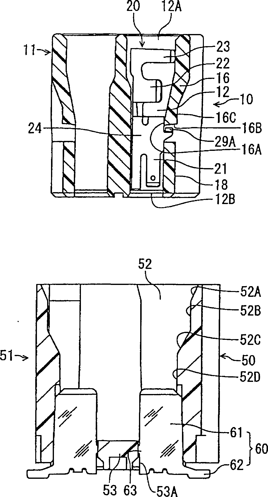
图2是显示图1中的II-II线的两个连接器的剖面图。FIG. 2 is a cross-sectional view of two connectors showing line II-II in FIG. 1 .
图3是显示图1中的本实施形态的连接器的局部外观的立体图。Fig. 3 is a perspective view showing a partial appearance of the connector of the present embodiment shown in Fig. 1 .
图4是显示使用于图1的连接器的端子的立体图。FIG. 4 is a perspective view showing terminals used in the connector of FIG. 1 .
图5是图4的端子的俯视图。FIG. 5 is a plan view of the terminal of FIG. 4 .
图6是图4的端子的展开图。FIG. 6 is an expanded view of the terminal of FIG. 4 .
图7是显示图2的两个连接器的嵌合后的剖面图。Fig. 7 is a cross-sectional view showing two connectors of Fig. 2 after mating.
符号说明Symbol Description
10:连接器 21A:接触部10:
11:壳体 22:连结部11: Housing 22: Connecting part
12:端子孔 24:弯曲部12: Terminal hole 24: Bending part
16:矛形部 26、27:竖立壁16: Spear-shaped
16A:引导面 26A、27A:缝隙16A:
16B:卡止前端面 28A:卡止部16B: locking
16C:被限制面 28A-1:后侧板面16C: Restricted
20:端子 29A:限制部20:
29A-1:限制面29A-1: Restricted Surface
具体实施方式 Detailed ways
以下根据图面说明作为本发明的一实施形态的电连接器、用于该电连接器的端子。An electrical connector according to an embodiment of the present invention and a terminal used for the electrical connector will be described below with reference to the drawings.
图1是显示本实施形态的电连接器(以下称为“连接器”)10与对方连接器50嵌合前的状态的立体图。FIG. 1 is a perspective view showing a state before an electrical connector (hereinafter referred to as "connector") 10 and a
在图1中,连接器10具有以电性絶缘材所制作的壳体11所保持的端子20,所述端子20被插入到呈二列地形成于该壳体11上的多个端子孔12。端子孔12在图1中朝上下方向贯通,与端子20连结的电缆(未图标)可从上侧开口部12A延伸出来,而后述的对方连接器50的端子的接触部可从下侧开口部12B(参照图2)进入。在壳体11的外侧壁上形成有突部13,在该突部13上形成有卡止孔13A。In FIG. 1 , a
对方连接器50是在与所述连接器10的端子20对应的位置上被壳体51保持着端子60。该壳体51上形成有可承接所述连接器10的嵌合部分的承接凹部52。在该壳体51的外侧面上安装有当与所述连接器10嵌合时用于防止脱落的金属板制的卡止构件55,该卡止构件55的上端朝内侧弯折,形成为与所述连接器10的壳体11上的卡止孔13A卡止的卡止部55A。所述端子60是维持金属板的板面的平坦状端子,具有贯通所述壳体51的底壁53并在所述承接凹部52的底部朝着上方的接触部61、和在底壁53的下方朝侧方弯折的连接部62(参照图2)。至于所述对方连接器50与连接器10的关联将在后面再次进行说明。In the
在连接器10的壳体11上,如显示图1的II-II线剖面的图2所示,形成有端子孔12。图2用二列端子孔12相互对向的各端子孔12的纵剖面(端子未剖面)来显示所述连接器10与对方连接器50嵌合前的状态,是图1中的II-II线剖面图。在图2中,在连接器10的端子孔12中右侧的一列插入有端子20(省略了所连结的电缆),左侧的一列则省略了端子。In the
形成于连接器10的壳体11上的端子孔12如图1及图2所示,呈前后(图2中的纵方向)延伸的大致方孔状,经过设置于纵方向上的中间部的倾斜内面,后部(图2中的上部)相对于前部而成为宽广的内部宽度,适合供后述的端子20插入。The terminal hole 12 formed on the
在壳体11的侧壁上,如图1所示,在所述排列方向,在将邻接的端子孔12彼此分隔的分隔壁位置上,形成从纵方向中间部朝前方延伸的后部纵沟槽14和使这些后部纵沟槽14连通的横沟槽15,通过邻接的两个后部纵沟槽14与横沟槽15,将向前方延伸的脚状的矛形部16形成于构成各端子孔12的侧壁上。图3是从外侧看该矛形部16及该矛形部16前方部分的放大立体图,如图3所示,端子孔12具有前端壁12C,而在该前端壁12C上,形成有可供对方连接器50的板状端子的接触部进入的缝隙状的贯通沟槽12D。该贯通沟槽12D与形成于壳体的侧壁上的前部纵沟槽17连通,该前部纵沟槽17与所述横沟槽15连通。在邻接的两个前部纵沟槽17彼此之间形成有片状侧壁18。因此,如上所述,因后部纵沟槽14在所述排列方向存在于邻接端子孔12彼此之间的分隔壁的位置,而前部纵沟槽17存在于端子孔12的中央位置,所以如图1及图3所示,在相同方向上,后部纵沟槽14与前部纵沟槽17偏移相当于端子孔12的排列间距一半的距离。On the side wall of the
矛形部16如上所述,由于所述后部纵沟槽14与横沟槽15的存在而呈朝前方的脚状并具有弹性,在图2中,可朝横(左右)方向弹性挠曲。该矛形部16的用于形成端子孔12的内面成为朝前方并向内侧倾斜的引导面16A,前端面形成为稍向外侧并向上方倾斜的卡止前端面16B。所述矛形部16的前端侧外面朝纵方向延伸而形成为被限制面16C。As mentioned above, due to the existence of the rear
图4、5所示的端子20通过对金属板进行冲压加工后再实施弯折加工来制作。该端子20是如图所示,在前端侧具有形成有接触部21A的接触片21,而在后端侧具有连结部22及保持部23,并在中间部具有弯曲部24。The terminal 20 shown in FIGS. 4 and 5 is produced by pressing a metal plate and then performing a bending process. As shown in the figure, the terminal 20 has a
接触片21是通过以朝所述后方向延伸并开口的方式形成在竖立的两侧的壁部上的缝隙21B,来设置将前端侧作为自由端的一对片状物。两个接触片21具有弹性并可朝相互的对向方向弹性挠曲,且在靠近自由端的位置上以缩小相互间隔的喉部来形成接触部21A。此一对接触部21A夹压对方连接器51的端子60来与该端子弹性接触。The
连结部22及保持部23以各自的竖立的两侧壁部形成一对U字状,通过铆接而将电缆予以压着连结并保持,且前后邻接设置。连结部22将电缆的芯线压着连结,而保持部23是以被覆的方式保持电缆。The
具有所述接触部21A的接触片21和连结部22及保持部23是公知的形态,在此不更进一步进行说明。The
在前后方向上位于所述接触片21与连结部22之间的弯曲部24具有从底壁25的两侧竖立的竖立壁26、27,该两个竖立壁26、27的板面相对向。卡止腕部28从一方的竖立壁26的上缘延伸出来,而限制腕部29从另一方的竖立壁27的上缘延伸出来。The
所述卡止腕部28是在所述一方的竖立壁26的上缘侧通过朝后方延伸并开口的缝隙26A而形成为腕状后,在其基部附近相对于板厚方向呈直角弯折而朝向另一方的竖立壁27。从该卡止腕部28的弯折部到自由端为止的部分形成为卡止部28A。所述限制腕部29是在另一方的竖立壁27上通过在所述缝隙26A的下方位置、即靠近弯曲部24的底壁25的位置上朝后方延伸并开口的缝隙27A而形成为腕状后,在其基部附近对板厚方向呈直角弯折而朝向所述一方的竖立壁26。从该限制腕部29的弯折部到自由端为止的部分形成为限制部29A。该限制部29A位于较所述卡止部28A更下方的位置。The locking
因所述限制腕部29位于较卡止腕部28的卡止部28A更下方的位置,利用其高度差形成与该限制腕部29的基部邻接并朝上方突出的突部30,在本实施形态中,所述卡止部28A的自由端的前侧板面以可与该突部30的后端面30A抵接的程度与之接近,或与之抵接。此卡止部28A的后侧板面28A-1插入到端子20的端子孔12后,与矛形部16的卡止前端面16B相面对。又,所述限制部29A的自由端的端面与所述竖立壁26接近,利用该限制部29A的L字状的板厚侧面形成限制面29A-1。Since the restricting
该本实施形态的端子20是对图6那样的金属板M通过冲压等加工出外形后再进行弯折加工,来将各部位做成图4、5所示的形态。在图6中,对于所述各部位标上与图4、5的对应部位相同的符号并省略其说明。图7中的一点划线则是用来显示弯折加工时的弯折位置的线。In the
以上概略说明的对方连接器50是如图1及图2所示,于壳体51上形成承接所述连接器10的承接凹部52。如图2所示,该承接凹部52具有适合于承接所述连接器10的内面形状,特别是与连接器10的矛形部16的外面对应的内面,依次具有导入斜面52A、开口侧纵面52B、中间斜面52C、以及深部纵面52D,形成与矛形部16的外面一致的形态。特别是所述深部纵面52D,当连接器嵌合结束时,位于与在连接器10的矛形部16的前端侧外面上形成的被限制面16C接近的位置。The
设置于该对方连接器50上的端子60是在维持金属板平坦面的状态下加工出外形,具有平板状的接触部61和从接触部的下端向壳体51外朝侧方延伸的连接部62。在所述接触部61的一方的侧缘上设有卡止突起63,所述接触部61从形成于壳体51的底壁53上的缝隙状的贯通孔53A被插入,所述卡止突起63咬入到贯通孔53A的侧壁面,藉以防止端子60脱离。所述接触部61的板面有助于在其上部与连接器10的端子20接触,而连接部62是当该对方连接器50被配置于电路基板上时,有助于与该电路基板的对应电路部焊接。The terminal 60 provided on the
以下说明关于本实施形态的端子及具有该端子的连接器的使用要领。The following describes how to use the terminal of the present embodiment and a connector having the terminal.
(1)首先,将电缆(未图标)压着连结到图4、5所示的端子20上。电缆是在前端部被除去被覆。以使露出的芯线位于连结部22、而被覆部分位于保持部23的方式配置该电缆,将所述连结部22及保持部23进行铆接,来将电缆压着连结并保持于端子20上。(1) First, a cable (not shown) is crimped and connected to the terminal 20 shown in FIGS. 4 and 5 . The cable is sheathed at the tip. The cable is arranged such that the exposed core wire is positioned at the connecting
(2)其次如图1及图2所示,将如此所获得的带电缆的端子经由开口部12A而从端子20的接触部21A侧插入到壳体11的端子孔12。在插入过程中,该端子20的卡止部28A(及该卡止部28A的前端所抵接的突部30)沿着壳体11的矛形部16的内面被引导并且按压该矛形部16的倾斜的引导面16A,使该矛形部16朝外侧挠曲地进行弹性变形,而能够使端子20更进一步插入。(2) Next, as shown in FIGS. 1 and 2 , the thus obtained terminal with cable is inserted into the terminal hole 12 of the
(3)当端子20的所述卡止部28A通过矛形部16的引导面16A时,矛形部16即不受来自卡止部28A的力,所以,从弹性变形状态释放而恢复原形。在此状态下,矛形部16的卡止前端面16B与所述端子20的卡止部28A的后侧板面28A-1相面对,而矛形部16的内面、即引导面16A与端子20的限制部29A的限制面29A-1抵接。藉此,即使电缆承受一些不经意的拉引力,端子20也会因卡止部28A卡止于矛形部16的卡止前端面16B而可防止端子20脱离。矛形部16也因与所述端子20的限制面29A-1抵接而不会产生朝内侧的挠曲。藉此,带电缆的端子被插入到各端子孔12,从而获得图1~3所示的连接器10。(3) When the locking
(4)插入有带电缆的端子的连接器10如图1及图2(省略电缆的图标)所示,在到达安装于电路基板(未图标)上的对方连接器50的上方位置后下降,从而插入到该对方连接器50的承接凹部52而结束嵌合(参照图7)。对方连接器50的板状的端子60的接触部61进入到连接器10的作为喉部的接触部21A彼此之间并被夹压,从而与所述端子20电性连接。又,连接器10的矛形部16的外面面对对方连接器50的承接凹部52的内面,特别是形成于矛形部16的外面上的被限制面16C与所述对方连接器50的承接凹部52的深部纵面52D接近并形成面接触,所以,在连接器嵌合状态下,即使带电缆的端子的电缆被不经意地拉引,矛形部16也由于所述深部纵面52D的作用而无法朝外侧弹性变形。(4) As shown in Fig. 1 and Fig. 2 (cable diagram is omitted), the
(5)藉此,矛形部16利用连接器10的端子20的限制部29A而限制了朝内侧的弹性变形,且在连接器嵌合状态下利用对方连接器50的壳体51而限制了朝外侧的弹性变形,所以,即使该矛形部16在卡止前端面16B受到来自端子20的卡止部28的大的力,也不会产生折曲,能保持正确的位置。因此,亦能可靠维持在所述卡止前端面16B上与端子20的卡止部28间的卡止状态。(5) With this, the elastic deformation of the
本发明不限于图标的形态,可进行各种变更实施,例如接触部、连结部可以是各种形态。接触部亦可为销状或板状的公型,连结部亦可为被焊锡连结的形态。The present invention is not limited to the form of the icon, and can be implemented with various changes, for example, the contact part and the connecting part can be in various forms. The contact part can also be a pin-shaped or plate-shaped male type, and the connection part can also be connected by solder.
Claims (6)
Applications Claiming Priority (2)
| Application Number | Priority Date | Filing Date | Title |
|---|---|---|---|
| JP2008275578A JP4674874B2 (en) | 2008-10-27 | 2008-10-27 | Electrical connector |
| JP2008-275578 | 2008-10-27 |
Publications (2)
| Publication Number | Publication Date |
|---|---|
| CN101728687A CN101728687A (en) | 2010-06-09 |
| CN101728687B true CN101728687B (en) | 2012-09-05 |
Family
ID=41650043
Family Applications (1)
| Application Number | Title | Priority Date | Filing Date |
|---|---|---|---|
| CN2009102080739A Active CN101728687B (en) | 2008-10-27 | 2009-10-22 | Electrical connector |
Country Status (6)
| Country | Link |
|---|---|
| US (1) | US7942708B2 (en) |
| EP (1) | EP2180553A2 (en) |
| JP (1) | JP4674874B2 (en) |
| KR (1) | KR20100047125A (en) |
| CN (1) | CN101728687B (en) |
| TW (1) | TWI422104B (en) |
Families Citing this family (16)
| Publication number | Priority date | Publication date | Assignee | Title |
|---|---|---|---|---|
| JP4674874B2 (en) * | 2008-10-27 | 2011-04-20 | ヒロセ電機株式会社 | Electrical connector |
| JP5446948B2 (en) * | 2010-02-02 | 2014-03-19 | 住友電装株式会社 | Terminal fitting |
| JP2012199190A (en) * | 2011-03-23 | 2012-10-18 | Yazaki Corp | Connector |
| US9024619B2 (en) * | 2011-07-14 | 2015-05-05 | Verathon Inc. | Connection system for sensor device |
| KR101389228B1 (en) | 2013-01-17 | 2014-04-29 | 심윤국 | Electricity connection connector and electricity connection apparatus for power distribution having the same |
| DE102013212717A1 (en) | 2013-06-28 | 2014-12-31 | Metalluk Bauscher Gmbh & Co Kg | Connectors |
| CN104979720B (en) * | 2014-04-08 | 2017-07-28 | 神讯电脑(昆山)有限公司 | Connector construction |
| DE102016106717B4 (en) * | 2016-04-12 | 2021-02-18 | Te Connectivity Germany Gmbh | Contact element and contact device with such a contact element |
| DE102017001166A1 (en) * | 2017-01-31 | 2018-08-02 | Kostal Kontakt Systeme Gmbh | Contact blade for a socket-like connector part and female connector part |
| WO2019178520A1 (en) | 2018-03-16 | 2019-09-19 | Fci Usa Llc | High density electrical connectors |
| JP7222694B2 (en) * | 2018-12-21 | 2023-02-15 | タイコエレクトロニクスジャパン合同会社 | contacts and connectors |
| JP2020102338A (en) * | 2018-12-21 | 2020-07-02 | タイコエレクトロニクスジャパン合同会社 | Connector housing and connector |
| JP7256961B2 (en) * | 2019-09-17 | 2023-04-13 | 住友電装株式会社 | Connectors and terminal fittings |
| JP7216896B2 (en) * | 2019-09-30 | 2023-02-02 | 住友電装株式会社 | Male terminals and male connectors |
| JP7447731B2 (en) * | 2020-08-07 | 2024-03-12 | 住友電装株式会社 | connector |
| JP7539023B2 (en) * | 2021-08-27 | 2024-08-23 | 株式会社オートネットワーク技術研究所 | connector |
Citations (4)
| Publication number | Priority date | Publication date | Assignee | Title |
|---|---|---|---|---|
| US5593328A (en) * | 1993-11-04 | 1997-01-14 | Sumitomo Wiring Systems, Ltd. | Female terminal fitting for connector |
| CN1466246A (en) * | 2002-06-06 | 2004-01-07 | 住友电装株式会社 | Terminal connector and connector |
| JP2005044586A (en) * | 2003-07-25 | 2005-02-17 | Jst Mfg Co Ltd | Plug for electrical connection |
| JP2005243359A (en) * | 2004-02-25 | 2005-09-08 | Sumitomo Wiring Syst Ltd | Connector |
Family Cites Families (13)
| Publication number | Priority date | Publication date | Assignee | Title |
|---|---|---|---|---|
| JPH04255677A (en) * | 1991-02-07 | 1992-09-10 | Fujikura Ltd | Connector housing |
| JP3361308B2 (en) * | 1999-12-28 | 2003-01-07 | タイコエレクトロニクスアンプ株式会社 | Female contact and electrical connector using the same |
| JP3750517B2 (en) * | 2000-11-29 | 2006-03-01 | 住友電装株式会社 | Terminal fitting |
| JP3599179B2 (en) * | 2000-12-21 | 2004-12-08 | 住友電装株式会社 | Connectors and terminal fittings |
| JP2002373728A (en) * | 2001-06-15 | 2002-12-26 | Sumitomo Wiring Syst Ltd | Connector |
| DE10150438A1 (en) * | 2001-10-12 | 2003-04-17 | Delphi Tech Inc | connector part |
| JP3864800B2 (en) * | 2002-02-15 | 2007-01-10 | 住友電装株式会社 | Connectors and male terminal fittings |
| JP3763574B2 (en) * | 2003-03-14 | 2006-04-05 | 日本航空電子工業株式会社 | connector |
| WO2004114467A1 (en) * | 2003-06-18 | 2004-12-29 | Ryosei Electro-Circuit Systems, Ltd. | Connection terminal |
| JP4442450B2 (en) * | 2005-02-02 | 2010-03-31 | 住友電装株式会社 | Terminal fitting |
| JP4165514B2 (en) * | 2005-02-02 | 2008-10-15 | 住友電装株式会社 | Terminal fitting |
| US7410384B2 (en) * | 2006-05-16 | 2008-08-12 | Fci Americas Technology, Inc. | Electrical contact with stapled connection |
| JP4674874B2 (en) * | 2008-10-27 | 2011-04-20 | ヒロセ電機株式会社 | Electrical connector |
-
2008
- 2008-10-27 JP JP2008275578A patent/JP4674874B2/en active Active
-
2009
- 2009-10-07 KR KR1020090094978A patent/KR20100047125A/en not_active Withdrawn
- 2009-10-14 TW TW098134788A patent/TWI422104B/en active
- 2009-10-21 US US12/603,016 patent/US7942708B2/en not_active Expired - Fee Related
- 2009-10-22 CN CN2009102080739A patent/CN101728687B/en active Active
- 2009-10-27 EP EP09013537A patent/EP2180553A2/en not_active Withdrawn
Patent Citations (4)
| Publication number | Priority date | Publication date | Assignee | Title |
|---|---|---|---|---|
| US5593328A (en) * | 1993-11-04 | 1997-01-14 | Sumitomo Wiring Systems, Ltd. | Female terminal fitting for connector |
| CN1466246A (en) * | 2002-06-06 | 2004-01-07 | 住友电装株式会社 | Terminal connector and connector |
| JP2005044586A (en) * | 2003-07-25 | 2005-02-17 | Jst Mfg Co Ltd | Plug for electrical connection |
| JP2005243359A (en) * | 2004-02-25 | 2005-09-08 | Sumitomo Wiring Syst Ltd | Connector |
Also Published As
| Publication number | Publication date |
|---|---|
| TWI422104B (en) | 2014-01-01 |
| JP4674874B2 (en) | 2011-04-20 |
| CN101728687A (en) | 2010-06-09 |
| US20100105229A1 (en) | 2010-04-29 |
| EP2180553A2 (en) | 2010-04-28 |
| US7942708B2 (en) | 2011-05-17 |
| JP2010103049A (en) | 2010-05-06 |
| TW201018005A (en) | 2010-05-01 |
| KR20100047125A (en) | 2010-05-07 |
Similar Documents
| Publication | Publication Date | Title |
|---|---|---|
| CN101728687B (en) | Electrical connector | |
| CN110416764B (en) | Electrical connector for circuit board | |
| US7556539B2 (en) | Connector | |
| JP4574692B2 (en) | Electrical connector | |
| US9246260B2 (en) | Electrical connector | |
| US9028277B2 (en) | Terminal locking structure in connector housing | |
| CN104283028B (en) | Electrical connector for flat conductive member | |
| JP2010267604A (en) | Electrical connector assembly | |
| CN112652902B (en) | Electrical connector for flat conductor | |
| JP3601772B2 (en) | connector | |
| CN110416774A (en) | Electric connector | |
| US20210083417A1 (en) | Connector and terminal fitting | |
| US6629864B2 (en) | Electrical contact for plug-in connector | |
| US11349242B2 (en) | Male wire terminal and male wire connector | |
| JP6050420B2 (en) | Electrical connector assembly | |
| US11264751B2 (en) | Male connector provided with housing that accomodates male terminal | |
| JP2009037955A (en) | Electrical connector for cable | |
| JP5249401B2 (en) | Electrical connector | |
| JP2010123518A (en) | Connector |
Legal Events
| Date | Code | Title | Description |
|---|---|---|---|
| C06 | Publication | ||
| PB01 | Publication | ||
| SE01 | Entry into force of request for substantive examination | ||
| C14 | Grant of patent or utility model | ||
| GR01 | Patent grant | ||
| CP02 | Change in the address of a patent holder |
Address after: Kanagawa Prefecture, Japan Patentee after: Hirose Electric Co.,Ltd. Address before: Tokyo, Japan Patentee before: Hirose Electric Co.,Ltd. |
|
| CP02 | Change in the address of a patent holder |