CN101784792A - Pump motor protector with redundant shaft seal - Google Patents
Pump motor protector with redundant shaft seal Download PDFInfo
- Publication number
- CN101784792A CN101784792A CN200880103689.3A CN200880103689A CN101784792A CN 101784792 A CN101784792 A CN 101784792A CN 200880103689 A CN200880103689 A CN 200880103689A CN 101784792 A CN101784792 A CN 101784792A
- Authority
- CN
- China
- Prior art keywords
- motor
- compensating element
- fluid
- water
- shaft sealing
- Prior art date
- Legal status (The legal status is an assumption and is not a legal conclusion. Google has not performed a legal analysis and makes no representation as to the accuracy of the status listed.)
- Granted
Links
Images


Classifications
-
- F—MECHANICAL ENGINEERING; LIGHTING; HEATING; WEAPONS; BLASTING
- F04—POSITIVE - DISPLACEMENT MACHINES FOR LIQUIDS; PUMPS FOR LIQUIDS OR ELASTIC FLUIDS
- F04D—NON-POSITIVE-DISPLACEMENT PUMPS
- F04D13/00—Pumping installations or systems
- F04D13/02—Units comprising pumps and their driving means
- F04D13/06—Units comprising pumps and their driving means the pump being electrically driven
- F04D13/08—Units comprising pumps and their driving means the pump being electrically driven for submerged use
- F04D13/10—Units comprising pumps and their driving means the pump being electrically driven for submerged use adapted for use in mining bore holes
-
- F—MECHANICAL ENGINEERING; LIGHTING; HEATING; WEAPONS; BLASTING
- F04—POSITIVE - DISPLACEMENT MACHINES FOR LIQUIDS; PUMPS FOR LIQUIDS OR ELASTIC FLUIDS
- F04D—NON-POSITIVE-DISPLACEMENT PUMPS
- F04D29/00—Details, component parts, or accessories
- F04D29/08—Sealings
- F04D29/10—Shaft sealings
-
- F—MECHANICAL ENGINEERING; LIGHTING; HEATING; WEAPONS; BLASTING
- F04—POSITIVE - DISPLACEMENT MACHINES FOR LIQUIDS; PUMPS FOR LIQUIDS OR ELASTIC FLUIDS
- F04D—NON-POSITIVE-DISPLACEMENT PUMPS
- F04D29/00—Details, component parts, or accessories
- F04D29/08—Sealings
- F04D29/10—Shaft sealings
- F04D29/106—Shaft sealings especially adapted for liquid pumps
Landscapes
- Engineering & Computer Science (AREA)
- Mechanical Engineering (AREA)
- General Engineering & Computer Science (AREA)
- Mining & Mineral Resources (AREA)
- Structures Of Non-Positive Displacement Pumps (AREA)
Abstract
一种可浸入水中的电动泵送装置具有电动机部分、泵部分、和保护器部分。保护器部分包括冗余的轴密封部分。
A submersible electric pumping device has a motor portion, a pump portion, and a protector portion. The protector portion includes a redundant shaft seal portion.
Description
相关申请related application
本申请要求2007年7月20日提交的申请号为60/951,080的美国申请的权益,该申请整体地包含在此。This application claims the benefit of US Application No. 60/951,080, filed July 20, 2007, which is hereby incorporated in its entirety.
技术领域technical field
本发明涉及可浸入水中的电动机和泵送系统,并且尤其涉及轴密封和与其连接的电动机保护器装置。This invention relates to submersible electric motors and pumping systems, and more particularly to shaft seals and motor protector devices connected thereto.
背景技术Background technique
流体位于地下。例如,流体可以包括碳氢化合物(原油)和水。至少用于消耗的原油的提取是必要的。在地面钻一个孔用于提取流体。该孔被称为井筒并且经常套装称作套管的金属管状结构。很多其它特征例如套管和井筒之间的水泥灌浆可以被添加。井筒可以是大体垂直的,并且甚至可以以多种方向被钻,例如向上或者水平。The fluid is located underground. For example, fluids may include hydrocarbons (crude oil) and water. At least the extraction of crude oil for consumption is necessary. Drill a hole in the ground to extract the fluid. This hole is called a wellbore and is often lined with a metal tubular structure called a casing. Many other features such as cement grouting between casing and wellbore can be added. The wellbore may be generally vertical, and may even be drilled in various directions, such as upward or horizontally.
一旦井筒被套装,套管可以被穿孔。穿孔涉及在套管上形成孔从而连接井筒套管的外侧至套管的内侧。可以通过下移穿孔枪至套管内实现穿孔。穿孔枪具有火药,其引爆并且推动物质穿过套管从而在套管和周围地层中形成孔,从而有助于地层流体从地层和井筒流入套管中。Once the wellbore is set, the casing may be perforated. Perforating involves forming holes in the casing to connect the outside of the wellbore casing to the inside of the casing. Perforation can be achieved by moving the perforation gun down into the cannula. The perforating gun has a charge that detonates and pushes material through the casing to create holes in the casing and surrounding formation, thereby facilitating the flow of formation fluids from the formation and the wellbore into the casing.
有时地层具有足够的压力以驱动井流体上升至地面。然而,这种情况不经常出现并且不能被信赖。人造提升设备因此可以被用于驱动下面的井流体向上流,例如至地面。人造提升设备被向下放置于套管内。人造提升设备通常具有带内部部件的电动机。防止井流体到达电动机的组成部件是所需的。Sometimes the formation has enough pressure to drive well fluids up to the surface. However, this happens infrequently and cannot be relied upon. Artificial lifting devices may thus be used to drive underlying well fluids upward, for example to the surface. The artificial lifting device is placed down inside the casing. Artificial lifting equipment usually has an electric motor with internal components. It is desirable to prevent well fluid from reaching the components of the motor.
附图说明Description of drawings
图1显示了特征实施例。Figure 1 shows a characteristic embodiment.
图2显示了特征实施例。Figure 2 shows a characteristic embodiment.
图3显示了特征实施例。Figure 3 shows a characteristic embodiment.
图4A-C显示了特征实施例。Figures 4A-C show characteristic embodiments.
图5显示了特征实施例。Figure 5 shows a characteristic embodiment.
图6显示了特征实施例。Figure 6 shows a characteristic embodiment.
图7显示了特征实施例。Figure 7 shows a characteristic embodiment.
发明内容Contents of the invention
某些特征的如下描述是示例性的并且不会以任何方式限制权利要求的范围或者整体公开。The following description of certain features is exemplary and does not limit the scope of the claims or the overall disclosure in any way.
一种特征实施例包括一种可浸入水中的电动泵装置,它具有可浸入水中的电动机部分,所述电动机部分产生转矩并且具有连接到其上的驱动轴,所述驱动轴传递转矩。所述驱动轴从所述电动机部分沿轴向方向延伸。保护器部分连接到所述电动机部分。所述驱动轴延伸到所述保护器部分中。所述保护器部分包括沿轴向方向延伸的管状套管。轴管环绕所述驱动轴的一部分从而在所述驱动轴的外表面与所述轴管的内部之间限定出空间。在所述轴管上的开口将所述轴管的内部与所述轴管的外部连接起来。第一补偿元件与所述开口连接。所述第一补偿元件是可扩张和可收缩的容器,所述容器限定了相应地可扩张和可收缩的容积。A featured embodiment includes a submersible electric pump assembly having a submersible motor portion that generates torque and has a drive shaft connected thereto that transmits the torque. The drive shaft extends in an axial direction from the motor portion. A protector part is connected to the motor part. The drive shaft extends into the protector portion. The protector portion includes a tubular sleeve extending in an axial direction. A shaft tube surrounds a portion of the drive shaft to define a space between an outer surface of the drive shaft and an interior of the shaft tube. An opening in the shaft tube connects the interior of the shaft tube with the exterior of the shaft tube. A first compensating element is connected to the opening. The first compensating element is an expandable and contractible container defining a correspondingly expandable and contractable volume.
另一特征实施例包括一种可浸入水中的电动泵装置,它包括可浸入水中的电动机部分,所述电动机部分产生转矩。所述电动机部分具有连接到其上的驱动轴,所述驱动轴传递转矩。所述驱动轴从所述电动机部分沿轴向方向延伸。泵部分与所述驱动轴可旋转地连接。保护器部分连接在所述电动机部分和所述泵部分之间。所述驱动轴延伸到所述保护器部分中,所述保护器部分包括沿轴向方向延伸的管状套筒,所述管状套筒具有限定内部容积的内表面。第一轴密封部分位于所述容积内并且将所述容积分隔成上部容积和下部容积。所述第一轴密封部分包括被偏压以仅允许远离所述电动机部分流动的第一安全阀。第二轴密封部分位于所述容积内并且分隔所述上部容积。所述第二轴密封部分包括被偏压以仅允许远离所述第一轴密封部分和所述电动机部分流动的第二安全阀。第一补偿元件补偿横过所述第二轴密封分割件的压力。所述第一补偿元件是可扩张和可收缩的容器,所述容器限定了相应地可扩张和可收缩的内部容积。至少一个电动机补偿元件与所述电动机部分流体连通,以补偿所述电动机部分内的流体的热膨胀和收缩。在热流体收缩过程中,流体容积在所述第一轴密封部分和所述第二轴密封部分之间,并且被防止流体地充足流回到所述电动机部分中,以贡献所述电动机部分中流体的超过一半的收缩补偿。Another featured embodiment includes a submersible electric pump apparatus including a submersible motor portion that generates torque. The motor portion has a drive shaft connected thereto that transmits torque. The drive shaft extends in an axial direction from the motor portion. A pump portion is rotatably connected to the drive shaft. A protector part is connected between the motor part and the pump part. The drive shaft extends into the protector portion including a tubular sleeve extending in an axial direction, the tubular sleeve having an inner surface defining an inner volume. A first shaft seal portion is located within the volume and divides the volume into an upper volume and a lower volume. The first shaft seal portion includes a first relief valve biased to allow flow only away from the motor portion. A second shaft seal portion is located within the volume and separates the upper volume. The second shaft seal portion includes a second relief valve biased to allow flow only away from the first shaft seal portion and the motor portion. A first compensating element compensates pressure across the second shaft seal segment. The first compensating element is an expandable and contractible container defining a correspondingly expandable and contractable inner volume. At least one motor compensating element is in fluid communication with the motor portion to compensate for thermal expansion and contraction of fluid within the motor portion. During thermal fluid contraction, the fluid volume is between the first shaft seal portion and the second shaft seal portion and is prevented from flowing sufficiently fluidly back into the motor portion to contribute More than half of the shrinkage of the fluid is compensated.
另一特征实施例包括一方法,该方法包括给所述电动机部分填充电动机流体;运行电动机并且提高所述电动机流体温度以及导致电动机流体热膨胀进入所述至少一个电动机补偿元件超过所述至少一个电动机补偿元件的最大容量、并且强制流体通过所述第一安全阀进入所述上部容积;接着降低所述电动机部分和保持在所述电动机部分内的所述电动机流体的温度以导致所述电动机部分中的电动机流体的热收缩,并且通过使所述至少一个电动机补偿元件收缩补偿所述热收缩;以及在收缩补偿过程中防止移动通过第一偏压安全阀的电动机流体返回。Another feature embodiment includes a method comprising partially filling the motor with motor fluid; operating the motor and increasing the motor fluid temperature and causing thermal expansion of the motor fluid into the at least one motor compensating element beyond the at least one motor compensating element. the maximum capacity of the element and force fluid through the first relief valve into the upper volume; then reduce the temperature of the motor section and the motor fluid held within the motor section to cause thermal contraction of motor fluid and compensating for said thermal contraction by contracting said at least one motor compensating element; and preventing return of motor fluid moving through the first biased relief valve during contraction compensation.
以上特征组合仅示意一些优选实施例并不以任何方式意味着限制本发明权利要求总体范围或申请人赋予的任何权利要求。The above combinations of features are merely illustrative of some preferred embodiments and are not meant to limit the general scope of the claims of the present invention or any claims issued by the applicant in any way.
详细说明Detailed description
在下文说明书中,许多细节说明被阐明以提供理解要求保护的主题。然而,本领域的技术人员应当理解本实施例可以没有这些细节实施并且描述的实施例的许多变化或者修改是可行的。In the following specification, numerous details are set forth to provide an understanding of claimed subject matter. However, it will be understood by those skilled in the art that the present embodiments may be practiced without these details and that many variations or modifications of the described embodiments are possible.
在说明书和所附权利要求书中:“连接”、“被连接”、“与…连接”和“使…连接”的任何术语都被用于指“直接连接”或“经过另一个元件连接”;并且术语“设置”被用于指“一个元件”或“一个以上元件”。当在此使用时,术语“向上”和“向下”、“上部”和“下部”、“向上地”和“向下地”、“上游”和“下游”、“上方”和“下方”、和其它表示相对给定点或元件上方或下方的位置的类似术语在本说明中使用用于更加清楚地描述一些实施例。此外,术语“密封机构”包括:封隔器、桥塞、井底阀、滑动套筒、阻隔塞组合、抛光座圈(PBR)密封件、和所有用于临时阻止流体流动通过井筒的其它方法和装置。另外,当使用术语“盘管”时,其实际上可由用于井下运行的接头管或者任何相对小直径的管所替代。In the specification and appended claims: any terms of "connected", "connected", "connected to" and "connected to" are used to mean "connected directly" or "connected via another element" and the term "disposition" is used to refer to "an element" or "more than one element". As used herein, the terms "upward" and "downward", "upper" and "lower", "upwardly" and "downwardly", "upstream" and "downstream", "above" and "below", and other similar terms denoting positions above or below relative to a given point or element are used in this description to more clearly describe some embodiments. Furthermore, the term "sealing mechanism" includes: packers, bridge plugs, downhole valves, sliding sleeves, barrier plug assemblies, polished bearing ring (PBR) seals, and all other methods used to temporarily prevent fluid flow through a wellbore and device. Also, when the term "coiled tubing" is used, it may actually be replaced by joint pipe or any relatively small diameter pipe used for downhole operation.
可浸入水中的泵送系统可以包括几个部分,例如可浸入水中的电动机部分和泵部分。可浸入水中的电动机部分为可浸入水中的泵部分提供能量。能量的传递是通过在电动机部分产生转矩和传递转矩,该转矩传递至连接到电动机部分的驱动轴。泵优选是离心类型泵或其它旋转型泵,该旋转型泵使用来自驱动轴的转矩驱动旋转叶轮以驱动井流体。本系统还可以包括多种附加的组件,例如用于连接可浸入水中的泵送系统至部署系统的连接器。开采管、线缆和盘管可以作为连接器被包括。电力可以经过电缆提供给可浸入水中的电动机部分,该电缆通过或者沿部署系统延伸。A submersible pumping system may consist of several sections such as a submersible motor section and a pump section. The submersible motor section powers the submersible pump section. Energy is transferred by generating torque in the motor section and transmitting the torque to a drive shaft connected to the motor section. The pump is preferably a centrifugal type pump or other rotary type pump that uses torque from a drive shaft to drive a rotating impeller to drive well fluid. The system may also include various additional components, such as connectors for connecting the submersible pumping system to the deployment system. Production tubing, cables and coiled tubing may be included as connectors. Power may be provided to the submersible motor section via cables that run through or along the deployment system.
通常,地下环境(特别是井流体)和从地面注入到井筒的流体(例如酸处理)包含CO2、H2S和盐水的腐蚀性化合物。那些腐蚀剂对于可浸入水中的泵送系统的组件有害,尤其是对电动机内部组件例如铜线圈和青铜轴承有害。此外,不管流体是否有腐蚀性,如果流体进入电动机并且与电动机油混合,流体会降低电动机油和电动机组件的绝缘材料的电介质和润滑性能。因此,希望保持外部流体与电动机内部流体和电动机组件分离。进入电动机部分的一种可能的方式是通过电动机部分和驱动轴之间的接触区域。其它接触面也是可能的入口。Typically, the subterranean environment (especially well fluids) and fluids injected into the wellbore from the surface (eg, acid treatment) contain corrosive compounds of CO2 , H2S , and brine. Those corrosive agents are detrimental to submersible pumping system components, especially motor internal components such as copper coils and bronze bearings. Additionally, whether the fluid is corrosive or not, if the fluid enters the motor and mixes with the motor oil, the fluid can degrade the dielectric and lubricating properties of the motor oil and the insulation of the motor components. Therefore, it is desirable to keep the external fluid separate from the motor internal fluid and motor components. One possible way of access to the motor part is through the contact area between the motor part and the drive shaft. Other contact surfaces are also possible inlets.
另一个考虑因素是电动机流体的热膨胀和/或收缩。例如可浸入水中的电动机可内部填充有流体,例如电介质油,该流体在运行期间便于冷却和润滑电动机。在许多应用中,由于地下环境、注入的流体、以及其它内部和外部因素,可浸入水中的电动机经受相当大的温度变化。这些温度变化可能使流体膨胀或者收缩。例如地下环境普遍存在的高温可能导致电动机流体膨胀超过电动机部分的最大容量,从而导致泄漏和对电动机组件的其它机械损坏。类似地,由于高温流体例如蒸汽喷射到可浸入水中的泵送系统可能导致不希望的流体膨胀和电动机损坏。另外,在膨胀之后,一旦电动机流体冷却的热收缩可能将井流体抽回至电动机,并携带之前提到的不希望的化合物。Another consideration is the thermal expansion and/or contraction of the motor fluid. Electric motors that are submersible, for example, may be internally filled with a fluid, such as dielectric oil, that facilitates cooling and lubricating the motor during operation. In many applications, submersible electric motors are subject to considerable temperature variations due to subterranean environments, injected fluids, and other internal and external factors. These temperature changes may cause the fluid to expand or contract. High temperatures, such as those prevailing in underground environments, may cause the motor fluid to expand beyond the maximum capacity of the motor section, resulting in leaks and other mechanical damage to the motor components. Similarly, undesired fluid expansion and motor damage may result from injection of high temperature fluid, such as steam, into submersible pumping systems. Additionally, after expansion, thermal contraction once the motor fluid cools may draw the well fluid back to the motor with the previously mentioned undesirable compounds.
因此,可浸入水中的电动机可以从可浸入水中的电动机保护器受益,电动机保护器适应膨胀/收缩的电动机流体同时保持防止井流体进入。而且,电动机的内部压力可以潜在地被允许与井筒内部建立的周围压力平衡或者至少大体平衡。因此,不难防止外部流体进入电动机流体和电动机内部组件。Accordingly, submersible motors can benefit from submersible motor protectors that accommodate expanding/contracting motor fluid while remaining well fluid-resistant. Also, the internal pressure of the motor can potentially be allowed to equilibrate, or at least substantially equilibrate, with the ambient pressure established inside the wellbore. Therefore, it is not difficult to prevent external fluids from entering the motor fluid and internal components of the motor.
而且,可浸入水中的电动机可以从保护器受益,该保护器带有冗余的轴密封部分,轴密封部分隔离在它们之间的流体容积,轴密封部分具有适应流体热膨胀和收缩的补偿器元件。Also, submersible electric motors can benefit from protectors with redundant shaft seal sections isolating the fluid volume between them with compensator elements to accommodate thermal expansion and contraction of the fluid .
而且,可浸入水中的电动机可以从保护器受益,该保护器与电动机部分液压地连接以便在热膨胀时过量流体可以从电动机部分1流出,并且膨胀补偿可以随着释放超过补偿器容量的过量流体一起发生,从而解除电动机部分或保护器充填过量流体的危险。Also, submersible motors can benefit from a protector that is hydraulically connected to the motor section so that excess fluid can escape from the
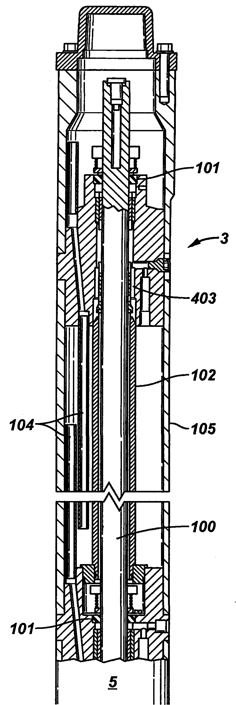
可浸入水中的电动泵(ESP)保护器的许多结构包括作为迷宫保护器的一部分的迷宫密封。图1显示了可浸入水中的电动泵单元的保护器部分3的一部分。保护器部分3中的轴管102具有邻近轴管102顶部的连通路径403。连通路径403的功能是使轴管102内的空间压力平衡,使得在轴管102顶部和底部的轴密封101不会出现过量正压或者过量负压,这有益于轴密封101的合适的功能。在一些应用中,例如SAGD水平井,迷宫保护器104被安装在保护器部分3中用于沉淀井的残余物。Many constructions of submersible electric pump (ESP) protectors include a labyrinth seal as part of the labyrinth protector. Figure 1 shows a part of the protector part 3 of a submersible electric pump unit. The
图2和3显示了保护器部分3,其具有迷宫保护器104和轴管102,轴管102被密封以阻止保护器部分3的腔室内的流体。电动机部分1显示为与补偿元件202流体连接,补偿元件202是波纹管,优选地补偿元件202围绕轴100延伸并且具有在其中形成空间的内部部分和外部部分,该空间在远离电动机部分1的端部被密封,由此限定波纹管围绕物。另外,为了补偿轴管102内部的流体例如电动机流体的热膨胀和收缩,小的补偿元件202(例如,金属波纹管、袋或者活塞)可以被设置成与连通路径403连接,例如轴管102上的开口。迷宫保护器腔室104显示为冗余密封配置的一部分。轴管102的端部优选被密封。安装O型环(或者其它密封件),用于使轴管102内的空间与环绕腔室完全密封。当轴管102的内部空间被密封时,由于轴管102内的油温变化,轴管102应该具有处理容积膨胀和收缩的补偿元件202,以便轴管102内的压力与轴管102外侧的压力大体平衡。否则,如果轴管102内侧空间经历高正压,顶部的轴密封101可能被抬起打开。如果轴管102内侧经历过量负压,迷宫部分下方的轴密封101可能被抬起打开。任一种方式,过量的正/负压力可能通过打开或者损坏密封件而损害保护器部分3。2 and 3 show the protector part 3 with a
如上解释,取决于应用,补偿元件202可以是轴向或者径向膨胀的小金属波纹管、弹性体袋或活塞(或者其它容积补偿机构)。对于传统应用,小弹性体(或其它抗油可扩张材料)袋足够使用。对于高温或者高腐蚀应用,小金属波纹管或者小活塞可能是最合适的选择。补偿元件可以与轴100同轴或者与轴100不同轴。As explained above, depending on the application, the compensating
保护器部分3可以结合保护器的任何其它部分或者组件,例如附加的迷宫保护器部分、袋保护器部分、金属波纹管保护器部分、活塞保护器部分等等。另外,如上所述的密封轴管空间可以被除了轴管空间的其它空间代替。例如,该空间可以由(弯曲的)管形成,该管连接顶部的轴密封的下端和底部的轴密封(未显示)的上端。并且,它可以是由多个轴密封部分或其它分隔装置隔离的容积。The protector part 3 may be combined with any other part or component of the protector, such as an additional labyrinth protector part, bag protector part, metal bellows protector part, piston protector part and the like. In addition, the sealed shaft tube space as described above may be replaced by other spaces than the shaft tube space. For example, the space may be formed by a (curved) tube connecting the lower end of the top shaft seal and the upper end of the bottom shaft seal (not shown). Also, it may be a volume separated by multiple shaft seal sections or other partitioning means.
图4A-C显示了呈可扩张隔膜404形式的补偿元件(例如,橡胶或者弹性体或甚至金属套筒)围绕轴管102上的连通路径密封。可扩张隔膜404提供容积补偿。轴管102显示为环绕轴100。轴管102可以是细长的轴向延伸管状元件。如先前暗指,会出现轴管102内的流体热膨胀的状态。因此,如图4A-C所示,连通路径403允许轴管102内的过量流体进入可扩张隔膜404从而解除压力。可扩张隔膜404可以是波纹管。图4A显示了轴管102上的连通路径403,连通路径403与可扩张隔膜或波纹管404的内侧连接。可扩张隔膜404显示为围绕连通路径403上方和下方的轴管102的圆向连接。图4B显示了在收缩状态的可扩张隔膜404。图4C显示了在膨胀状态的可扩张隔膜404。4A-C show a compensating element in the form of an expandable membrane 404 (eg, a rubber or elastomer or even a metal sleeve) sealing around the communication path on the
本申请中的图5示意性显示了在井10内的可浸入水中的电动泵送装置。井10被钻进地层16和地岩层13。井10套装套管14。可浸入水中的电动泵送装置具有电动机部分1和泵部分2。电动机部分1可以在其中具有电动机流体。保护器部分3被连接在电动机部分1和泵部分2之间、并且其包括多个轴密封部分33(图6中所示)。保护器部分3适合于允许膨胀并且排出过量电动机流体,同时例如在任何热收缩时阻止和/或防止井流体向电动机部分1进入。补偿元件5位于电动机部分1下方以允许电动机流体膨胀和收缩。还包括冷却器7和量计6。泵部分2连接至有接头的或盘绕的管9。泵部分1可以是离心类型泵或其它旋转类型泵。电动机部分1从向上延伸的电缆11接收电力。推力轴承8可以位于保护器部分3和电动机部分1之间。开采流体流12被显示流至与泵部分2连接的入口4。FIG. 5 of the present application schematically shows a submersible electrokinetic pumping device within a
图6是保护器部分3的一个实施例的剖面的示意图,其包括轴密封部分33a-d。电动机部分1具有在电动机部分1下方连接的电动机补偿元件5。通常电动机补偿元件5具有补偿容积,该补充容积是电动机部分1的最大油容量的至少1/10,例如,1/6。保护器部分3内的补偿元件33a-d具有总计补偿容积,该容积通常小于电动机部分1的最大油容量的1/20,尽管它可能的范围例如像1/50、或者1/75、1/100或者更小值一样低。电动机部分1具有沿轴向方向从其延伸的驱动轴100。电动机补偿元件5被显示为波纹管,优选是金属的。然而电动机补偿元件5可以采用多种形式,包括但是并不限于囊状物或者活塞,或者任何其它可扩张并且可收缩的容器,该容器限定了相应地可扩张和可收缩的容积。保护器部分3在电动机部分1上方并且具有围绕轴100的轴密封部分33a-d。保护器部分3可以具有纵向延伸的管形套管105,该管形套管具有限定内部容积的内表面。每个轴密封部分33a-d位于该内部容积中,并且可被连接在管型套管105内表面和轴100之间。不需要轴密封部分33a-d和轴100直接接触,尽管这样是可能的。每个轴密封部分33a-d都具有邻近轴100的轴密封101。每个轴密封101可以包含弹性体材料以至紧密地符合轴100的表面。每个轴密封101也可以包含金属、陶瓷、或者聚合体。每个轴密封部分33a-d用于分隔保护器部分3中的容积,例如,将保护器部分3分隔成单独的流体容纳容积,这些容积与电动机部分1相继地流体隔离。轴100沿轴向方向从电动机部分1延伸到保护器部分3并且向上进入泵部分2(未显示)。链轮206被显示并且在链轮206和第一轴密封部分33a之间形成气泡池208。气泡池208是收集气泡的腔室,气泡可以上升到隔离气泡的腔室内的电动机部分1的油中。Figure 6 is a schematic illustration of a cross-section of one embodiment of the protector portion 3, which includes
实际上,假定电动机部分1可能经受的温度范围和所获得的热膨胀,很难确定精确的电动机油量以满足要求同时避免过量填充电动机部分1。而且,电动机油从制造(例如,75℉)至运送和存储(例如,-40℉)、至安装(例如,60℉)、至运行(例如,600℉)、至不运行(例如,500℉)经受更大的热收缩和膨胀。因此,没有安全阀,会需要更大容量的补偿。因此,提供电动机补偿元件5,并且第一轴密封部分33a具有安全阀201a。在正常运行过程中,安全阀201a可以被偏压,优选地仅允许远离电动机部分1流动。安全阀201a处于延伸经过第一轴密封33a例如穿过开口209a的流动路径中。提供安全阀201a允许过量流体从电动机部分1中溢出,并且提供安全阀201a是有益的由于它允许电动机部分1内的流体容积的自调节。In practice, given the temperature range to which the
第一轴密封部分33a的上方是具有安全阀201b和补偿元件202b的第二轴密封部分33b。在希望更完美地使电动机部分1与保护器部分流体地隔离、或者更完美地流体隔离轴密封部分之间的容积的情况下,安全阀201b能够卸除并且可以提供连接电动机部分1至井筒的安全阀。补偿元件202b被显示为与电动机部分1、泵部分2、套管205和轴100不同轴,但是补偿元件202b也可以是同轴的。安全阀201b是偏压的单向阀并且处于延伸经过第二轴密封部分33b例如穿过开口209b的流动路径中。补偿元件202b是可扩张和可收缩的容器,其界定了相应地可扩张和可收缩的内部容积。补偿元件202b经过轴密封分隔补偿压力。例如,补偿元件202b可以是波纹管。波纹管可以是金属波纹管,但可以是其它材料。补偿元件202b也可以是活塞或者囊状物.这些特征可以适用于本申请讨论的所有补偿元件。Above the first
第二轴密封部分33b的上方是具有安全阀201c和两个补偿元件202c的第三轴密封部分33c,两个补偿元件202c都显示为波纹管。再次,在希望使电动机部分1与保护器部分液压地隔离、或者液压地隔离在轴密封部分之间限定的容积的情况下,安全阀201c可以被卸除。安全阀201c可以是单向阀并且处于延伸穿过第三轴密封部分33c例如通过开口209c的流动路径上。安全阀201c可以被偏压仅允许远离电动机部分1流动。Above the second
第三轴密封部分33c的上方是具有安全阀201d和显示为波纹管的补偿元件202d的第四轴密封部分33d。再次,在希望使电动机部分1与保护器部分更完美地液压地隔离、或者使轴密封部分之间的容积隔离的情况下,安全阀201d可以被卸除。安全阀201d可以是单向阀并且处于穿过轴密封部分33d例如通过开口209d的流动路径上。一个腔室在第四轴密封部分33d上方并且具有通向井筒15的释放通道204d。安全阀201d可以被偏压仅允许远离电动机部分1流动。Above the third
在运行期间,假定图6显示的实施例,可以发生电动机部分1中的流体容积的自调节。在制造或者安装时电动机部分1可以填充电动机流体。当电动机部分1的流体变热并且热膨胀时,电动机补偿元件5扩张以补偿膨胀。如果考虑热膨胀而放入过多流体,电动机补偿元件5达到容量,电动机部分1中的流体膨胀超过电动机部分1和电动机补偿元件5的容量,并且任何过量流体流经安全阀201a并且经过第一轴密封部分33a进入容积。安全阀可以通过套管通向井筒。流经第一安全阀201a的过量流体使补偿元件202b扩张。如果补偿元件202b达到容量,过量流体流经安全阀201b。此外,补偿元件202b的扩张排移轴密封部分33b后面的容积。除了补偿元件202b排移的容积以外,经过第二轴密封部分33b上方的流体使补偿元件33c扩张。如果两个补偿元件33c达到容量,过量流体流经安全阀201c并且使补偿元件202d扩张。如果补偿元件202d达到容量,过量流体流经安全阀201d并且从释放通道204d到井筒15。During operation, assuming the embodiment shown in FIG. 6 , a self-regulation of the fluid volume in the
如图6所示,一旦电动机部分1和相应的流体冷却,电动机补偿元件5将收缩,从而补偿电动机部分1内流体的热收缩。保护器部分3内的流体可以冷却并且也可以收缩。然而,流经安全阀201a的过量流体将被防止返回到电动机部分1。一旦在轴密封部分33a-d之间容积内的流体冷却,补偿器202b-d可以收缩并且补偿热收缩。As shown in FIG. 6 , once the
本发明特征涉及有关电动机部分1内的流体量的自调节的构思的电动机补偿元件5和补偿元件202b-d的相对尺寸。也就是说,电动机补偿元件5尺寸被选择成其可以基本上被预期补偿电动机部分1内的流体的所有热膨胀。例如补偿元件202b-d合计可具有比电动机补偿元件5小很多的容积,例如,优选至多为电动机补偿元件5的容积的1/10。或者,补偿元件202和电动机补偿元件5的容积比可以大约为2/10、3/10、2/5或者1/2。假定图6中的配置,补偿元件202b-d连同释放端口204的小容积,允许在通过膨胀和压缩的初始填充时电动机部分1的电动机流体量的自调节。换句话说,轴密封部分33a-d之间的空间在收缩时被安全阀201a-d隔离,从而防止到电动机部分1的回流。The inventive feature relates to the relative dimensions of the
应当指出,附加的轴密封部分和补偿器可以以任何数目或者次序随图6中显示的那些被增加。而且,图6中显示的次序仅仅是实施例的示例并且不起限制作用。It should be noted that additional shaft seal sections and compensators may be added in any number or order other than those shown in FIG. 6 . Also, the order shown in FIG. 6 is merely an example of an embodiment and is not limiting.
优选第一轴密封部分33a仅具有安全阀201a。然而,应当理解的是,轴密封部分33a-d可以采用许多配置变化。例如,优选至多占电动机补偿元件5的容积的1/10的补偿元件可以增加至轴密封部分33a在此而不会危害该构思。例如,轴密封部分33d可以依序位于任何位置,例如,直接置于第一轴密封部分33a后面。而且,轴密封部分33b可以具有一个补偿元件202b并且轴密封部分33c可以具有一个补偿元件202c。或者,两个补偿元件33c可以被具有相同总体最大容积排移量的单个补偿元件33c代替。或者,可以使用多于两个的补偿元件33c。而且,再次,安全阀可以被卸除。It is preferable that the first
过滤器207可以被提供。图2显示了设置在流体流动路径中在第二轴密封部分33b和第三轴密封部分33c之间过滤器。然而,过滤器207可以被放置在任何位置,只要过滤器207是在流体流动路径中并且流体经过一个轴密封部分通过过滤器207流至另一个轴密封部分。过滤器207可以被放置在第四轴密封部分33c上方、或者甚至在第一轴密封部分33a下方。一个以上的过滤器207也可以被用于不同位置。过滤器207可以帮助防止井流体中的颗粒或者其它污染物进入电动机部分1。A
图7是一个液压回路图形,其显示了在本申请的其它图中具体化的构思,涉及可浸入水中的电动泵送装置和相关的组件。图7显示了三个轴密封部分33a-c,它们由虚线圈定。实线显示流体流动路径。电动机1被显示具有连接在电动机1下方的电动机补偿元件5。电动机补偿元件5可以是波纹管。第一轴密封部分33a在电动部分1上方并且在一条流体流动路径内具有轴密封101a。过滤器207在轴密封101a后面并且在流动路径中。安全阀201a在另一条流体流动路径中。安全阀201a可以是一个单向阀,例如,被偏压优先地仅允许远离电动机部分1流动的偏压阀。过滤器207跟随安全阀201a。图7显示了在第一轴密封部分33a内的两个单独的过滤器207,但是这两个过滤器207可以由单个过滤器207或两个以上过滤器207替换。保护器部分可以是在其中的并且是其本身的过滤器。Figure 7 is a hydraulic circuit diagram showing the concept embodied in other figures of this application, involving a submersible electric pumping device and associated components. Figure 7 shows three
第一轴密封部分33a通向第二轴密封部分33b。第二轴密封部分33b内的流体流动路径通过轴密封101b。优选地,该路径由轴密封101b完全阻截。另一条平行流体流动路径通过安全阀201b,该安全阀是单向阀,该单向阀可被偏压以优先允许远离电动机部分1流动。另一条平行流体流动路径是通过显示为波纹管的补偿元件202b。过滤器207被显示在第二轴密封部分33b的外部。应当指出,第二轴密封部分33b中的过滤器207在虚线外部,但是可以在虚线内部,例如,轴密封部分可以根据优选设计考虑包括或排除过滤器207。The first
第二轴密封部分33b通向第三轴密封部分33c。如上所示,过滤器207位于第二轴密封部分33b和第三轴密封部分33c之间。第三轴密封部分33c具有阻截一条流体流动路径的轴密封101c。优选地,轴密封101c完全阻截这条流体流动路径。安全阀201c处于另一条平行流体流动路径,安全阀优选是单向的,例如,被偏压以优先仅允许远离电动机部分1流动。两个补偿元件202c阻截其它的平行流体流动路径。一个单独的过滤器207被显示在第三轴密封部分33c内,但是也可以在第三轴密封部分33c的外部。而且,可以使用多个过滤器207。第三轴密封部分33c可以通向井筒15。The second
在运行过程中,如图7所示,电动机部分1内的流体可能经受热膨胀。一旦膨胀,流体可膨胀至电动机补偿元件5。如果热膨胀流体从未超过电动机部分1和电动机补偿元件5的最大容量,轴密封部分33a-c可以没有安全阀、并且是液压隔离同时保护电动机部分1。然而,在流体超过电动机部分1和电动机补偿元件5的容积的情况下,提供安全阀201a-c可以比提供从电动机部分1和电动机补偿元件5直接到井筒15的单个安全阀更加有益,因为这种安全阀仅为井流体进入提供单一阻挡并且该安全阀直接暴露在有害的井筒环境中。例如,当电动机补偿元件5达到最大容量时,流体可以膨胀通过第一轴密封部分33a的安全阀201a。轴密封101a优选阻截所有流体沿此路径流动。流体优选移动通过第一轴密封部分33a内的安全阀201a流动。流体移动通过过滤器207。During operation, as shown in Figure 7, the fluid within the
流体然后膨胀进入第二轴密封部分33b并且膨胀进入补偿元件202b。优选地,没有流体移动通过由轴密封101b阻截的路径。一旦补偿元件202b达到最大容量,任何过量流体将移动通过安全阀201b并且通过过滤器207进入第三轴密封部分33c。The fluid then expands into the second
流体流经第三轴密封部分33c从而排移流体。而且,排移是由补偿元件202b的扩张导致。因此,流体使两个补偿元件202c扩张,从而排移足够容积。一旦补偿元件202c达到最大容量,任何过量容积经过安全阀201c通过过滤器207并且到达井筒15。Fluid flows through the third
一旦电动机部分1内的流体冷却,电动机补偿元件5就将收缩并且补偿流体的热收缩。当隔离在轴密封部分33a-c之间的流体容积热收缩时,补偿元件202b和202c补偿这种热收缩。Once the fluid in the
一些附加的特征涉及保护器部分3的装配。如图6显示,连接到相应轴密封部分33a-d的套管105的各部分可以通过螺纹连接210a-d连接在一起。螺纹连接可以绕套管105的各部分的周向延伸。螺纹连接210a-d允许简化安装,因为轴密封33a-d可以在轴100上降低并且旋入到位。Some additional features relate to the fit of the protector part 3 . As shown in FIG. 6, the portions of the
尽管本申请中讨论了涉及发明构思的多个实施例,本领域的技术人员可以理解的是,可预期和想象对这些实施例进行不同修改和变化。这种修改和变化都不脱离所附权利要求书的真正的精神和范围。While various embodiments involving inventive concepts are discussed in this application, those skilled in the art will appreciate that various modifications and variations to these embodiments are contemplated and imagined. Such modifications and changes do not depart from the true spirit and scope of the appended claims.
Claims (24)
- One kind can water-immersed motor-drive pump device, comprising:Can water-immersed motor portion, described motor portion produces torque and live axle is connected on the described motor portion, described live axle transmitting torque, described live axle in axial direction extends from described motor portion;Be connected to the protector part of described motor portion, described live axle extends in the described protector part, and described protector partly comprises the tubular sleeve that in axial direction extends;Central siphon, thus described central siphon limits the space around the part of described live axle between the inside of the outer surface of described live axle and described central siphon;Opening on described central siphon, described opening couples together the inside of described central siphon and the outside of described central siphon;First compensating element that is connected with described opening, described first compensating element is expansible and collapsible container, described container defines correspondingly expansible and contractile volume.
- 2. as claimed in claim 1 can water-immersed motor-drive pump device, it is characterized in that, comprising:With the motor compensating element that described motor portion fluid is connected, described motor compensating element is expansible and collapsible container, and described container defines correspondingly expansible and contractile volume.
- 3. as claimed in claim 1 can water-immersed motor-drive pump device, it is characterized in that, comprising:Be positioned at the first shaft sealing part of described volume; WithBe positioned at the second shaft sealing part of described volume;Described central siphon is with described first shaft sealing part and described second shaft sealing partly is connected and extension between described first shaft sealing part and described second shaft sealing branch.
- 4. as claimed in claim 1 can water-immersed motor-drive pump device, it is characterized in that described first compensating element is a metal bellows.
- 5. as claimed in claim 1 can water-immersed motor-drive pump device, it is characterized in that described first compensating element is a piston/cylinder.
- 6. as claimed in claim 1 can water-immersed motor-drive pump device, it is characterized in that described first compensating element is the elastomer bladder.
- 7. as claimed in claim 1 can water-immersed motor-drive pump device, it is characterized in that described first compensating element and described axle disalignment.
- 8. as claimed in claim 1 can water-immersed motor-drive pump device, it is characterized in that described first compensating element is coaxial with described axle.
- 9. as claimed in claim 2 can water-immersed motor-drive pump device, it is characterized in that described motor compensating element is a metal bellows.
- 10. as claimed in claim 1 can water-immersed motor-drive pump device, it is characterized in that, comprise labyrinth protector sealing.
- 11. as claimed in claim 1 can water-immersed motor-drive pump device, it is characterized in that, comprise the pump part that is connected with described live axle.
- 12. as claimed in claim 1 can water-immersed motor-drive pump device, it is characterized in that, comprise the safety valve of volume and sleeve volume outward in the coupling sleeve.
- 13. one kind can water-immersed motor-drive pump device, comprising:Can water-immersed motor portion, described motor portion produces torque and live axle is connected on the described motor portion, described live axle transmitting torque, described live axle in axial direction extends from described motor portion;The pump part that rotatably is connected with described live axle;Be connected the protector part between described motor portion and the described pump part, described live axle extends in the described protector part, and described protector partly comprises:The tubular sleeve of Yan Shening in axial direction, described tubular sleeve have the internal surface that limits internal capacity;Be positioned at described volume and described volume separation is become the first shaft sealing part of upper volume and lower volume, the described first shaft sealing branch comprises:Biased first safety valve only to allow to flow away from described motor portion;Be positioned at described volume and separate the second shaft sealing part of described upper volume, the described second shaft sealing branch comprises:Biased only to allow away from described first shaft sealing part and the second mobile safety valve of described motor portion;First compensating element of the pressure of the described second shaft sealing cut piece is crossed in compensation, and described first compensating element is expansible and collapsible container, and described container defines correspondingly expansible and contractile internal capacity; AndAt least one motor compensating element, described at least one motor compensating element is communicated with described motor portion fluid, with thermal expansion and the contraction that compensates the fluid in the described motor portion;Wherein, in the hot fluid contraction process, the shrinkage-compensating that surpasses half that the fluid displacement between described first shaft sealing part and described second shaft sealing divide flow back in the described motor portion with being prevented from fluid and contributes fluid in the described motor portion.
- 14. as claimed in claim 13 can water-immersed motor-drive pump device, it is characterized in that, comprise the 3rd shaft sealing part, described the 3rd shaft sealing branch comprises second compensating element, the pressure of described the 3rd shaft sealing part cut piece is crossed in described second compensating element compensation, described second compensating element is expansible and collapsible container, and described container defines correspondingly expansible and contractile internal capacity.
- 15. as claimed in claim 14 can water-immersed motor-drive pump device, it is characterized in that the maximum volume of described second compensating element is greater than the maximum volume of described first compensating element.
- 16. as claimed in claim 13 can water-immersed motor-drive pump device, it is characterized in that, comprise the 3rd shaft sealing part, described the 3rd shaft sealing branch comprises the second and the 3rd compensating element, the pressure of described the 3rd shaft sealing part cut piece is crossed in the compensation of the described second and the 3rd compensating element, the described second and the 3rd compensating element is respectively expansible and collapsible container, and described container defines correspondingly expansible and contractile internal capacity.
- 17. as claimed in claim 16 can water-immersed motor-drive pump device, it is characterized in that described the 3rd shaft sealing branch comprises:Biased only to allow away from described first shaft sealing part and the 3rd mobile safety valve of described motor portion.
- 18. as claimed in claim 13 can water-immersed motor-drive pump device, it is characterized in that, comprise at least one the motor compensating element that is connected with described motor portion fluid, described at least one motor compensating element is expansible and collapsible container, and described container defines correspondingly expansible and contractile internal capacity; WithWherein, the maximum volume of described at least one motor compensating element is greater than the maximum volume of described first compensating element.
- 19. as claimed in claim 18 can water-immersed motor-drive pump device, it is characterized in that the described maximum volume of described at least one motor compensating element is to be included at least 1/10 of motor fluid volumes in the described motor portion.
- 20. as claimed in claim 18 can water-immersed motor-drive pump device, it is characterized in that the maximum volume of described at least one motor compensating element is than at least 5 times greatly of the greatest combined volumes of described first compensating element and described second compensating element.
- 21. as claimed in claim 13 can water-immersed motor-drive pump device, it is characterized in that the maximum volume of described at least one motor compensating element is than at least 10 times greatly of the maximum volumes of described first compensating element.
- 22. as claimed in claim 13 can water-immersed motor-drive pump device, it is characterized in that described at least one motor compensating element is a bellows, and described first compensating element is a bellows.
- 23. as claimed in claim 13 can water-immersed motor-drive pump device, it is characterized in that, comprise at least one filter that is arranged in fluid flow path.
- 24. the method for the self-regulation motor fluid displacement in can water-immersed motor-drive pump device, described motor-drive pump device have produce torque can water-immersed motor portion, the described live axle that can water-immersed motor portion has a connection transmitting torque thereon, described live axle in axial direction extends from described motor portion;The pump part that rotatably is connected with described live axle;Be connected the protector part between described motor portion and the described pump part, described live axle extends in the described protector part, and described protector partly comprises:The tubular sleeve of Yan Shening in axial direction, described tubular sleeve have the internal surface that limits internal capacity;Be positioned at described volume and described volume separation is become the first shaft sealing part of upper volume and lower volume, the described first shaft sealing branch comprises:Biased first safety valve only to allow to flow away from described motor portion;Be positioned at described volume and separate the second shaft sealing part of described upper volume, the described second shaft sealing branch comprises:Biased only to allow away from described first shaft sealing part and the second mobile safety valve of described motor portion;First compensating element of the pressure of the described second shaft sealing cut piece is crossed in compensation, and described first compensating element is expansible and collapsible container, and described container defines correspondingly expansible and contractile internal capacity; AndAt least one motor compensating element, described at least one motor compensating element is communicated with described motor portion fluid, with thermal expansion and the contraction that compensates the fluid in the described motor portion;Described method comprises:Fill the motor fluid for described motor portion;Service meter and improve described motor fluid temperature (F.T.) and cause the motor thermal expansion to enter described at least one motor compensating element and surpass the maximum capacity of described at least one motor compensating element and force fluid to enter described upper volume by described first safety valve;The temperature that then reduces described motor portion and remain on the described motor fluid in the described motor portion to be causing the thermal shrinkage of the motor fluid in the described motor portion, and by making the described thermal shrinkage of described at least one motor compensating element shrinkage-compensating; AndPrevent that in the shrinkage-compensating process motor fluid that moves through the first bias voltage safety valve from returning.
Applications Claiming Priority (3)
| Application Number | Priority Date | Filing Date | Title |
|---|---|---|---|
| US95108007P | 2007-07-20 | 2007-07-20 | |
| US60/951,080 | 2007-07-20 | ||
| PCT/US2008/070529 WO2009015035A1 (en) | 2007-07-20 | 2008-07-18 | Pump motor protector with redundant shaft seal |
Publications (2)
| Publication Number | Publication Date |
|---|---|
| CN101784792A true CN101784792A (en) | 2010-07-21 |
| CN101784792B CN101784792B (en) | 2013-06-12 |
Family
ID=40281736
Family Applications (1)
| Application Number | Title | Priority Date | Filing Date |
|---|---|---|---|
| CN200880103689.3A Expired - Fee Related CN101784792B (en) | 2007-07-20 | 2008-07-18 | Pump motor protector with redundant shaft seal |
Country Status (5)
| Country | Link |
|---|---|
| US (2) | US8807966B2 (en) |
| CN (1) | CN101784792B (en) |
| CA (1) | CA2694081C (en) |
| GB (2) | GB2463224B (en) |
| WO (1) | WO2009015035A1 (en) |
Cited By (2)
| Publication number | Priority date | Publication date | Assignee | Title |
|---|---|---|---|---|
| CN110494625A (en) * | 2017-04-07 | 2019-11-22 | 齐立富控股有限公司 | Modular labyrinth seal system for use with electric submersible pumps |
| CN113565957A (en) * | 2021-05-19 | 2021-10-29 | 上海工程技术大学 | Dynamic and static seal and pressure balance combined device for deep well micro high pressure liquid station system |
Families Citing this family (25)
| Publication number | Priority date | Publication date | Assignee | Title |
|---|---|---|---|---|
| US20110236233A1 (en) * | 2010-03-24 | 2011-09-29 | Baker Hughes Incorporated | Double Sealing Labyrinth Chamber for Use With a Downhole Electrical Submersible Pump |
| US8651836B2 (en) | 2011-04-08 | 2014-02-18 | Baker Hughes Incorporated | Torque transmitting rings for sleeves in electrical submersible pumps |
| US8845308B2 (en) | 2011-04-14 | 2014-09-30 | Baker Hughes Incorporated | Electric submersible pump (ESP) thrust module with enhanced lubrication and temperature dissipation |
| US8726981B2 (en) | 2011-06-01 | 2014-05-20 | Baker Hughes Incorporated | Tandem progressive cavity pumps |
| US8925928B2 (en) | 2012-11-28 | 2015-01-06 | Ge Oil & Gas Esp, Inc. | Mechanical seal with PFA bellows |
| US10094206B2 (en) * | 2013-02-07 | 2018-10-09 | Oilfield Equipment Development Center Limited | High temperature motor seal for artificial lift system |
| US20150132158A1 (en) * | 2013-11-08 | 2015-05-14 | Ge Oil & Gas Esp, Inc. | Electric submersible motor oil expansion compensator |
| US9322401B2 (en) * | 2014-02-10 | 2016-04-26 | General Electric Company | Linear compressor |
| RU2551596C1 (en) * | 2014-05-29 | 2015-05-27 | Иван Соломонович Пятов | Filtering module |
| CA2959496C (en) | 2014-08-29 | 2021-03-09 | Ge Oil & Gas Esp, Inc. | Fluid expansion chamber with protected bellow |
| CA2961631A1 (en) * | 2014-09-17 | 2016-03-24 | Ge Oil & Gas Esp, Inc. | Redundant esp seal section chambers |
| WO2016053658A1 (en) * | 2014-10-02 | 2016-04-07 | Schlumberger Canada Limited | Motor compensator and shaft seal module arrangement for electric submersible pumping system |
| US9920774B2 (en) * | 2015-08-21 | 2018-03-20 | Energy Recovery, Inc. | Pressure exchange system with motor system and pressure compensation system |
| US10228062B2 (en) * | 2015-09-11 | 2019-03-12 | Ge Oil & Gas Esp, Inc. | Modular seal section with external ports to configure chambers in series or parallel configuration |
| WO2017066032A1 (en) | 2015-10-11 | 2017-04-20 | Schlumberger Technology Corporation | Submersible pumping system thrust bearing gas venting |
| CA3041312A1 (en) | 2016-10-23 | 2018-04-26 | Schlumberger Canada Limited | Gas purging for electric submersible pumping system |
| DE102017206498A1 (en) * | 2017-04-18 | 2018-10-18 | Robert Bosch Gmbh | Pressure compensation device set up for underwater applications |
| US10781811B2 (en) | 2017-06-24 | 2020-09-22 | Ge Oil & Gas Esp, Inc. | Volumetric compensator for electric submersible pump |
| US11168769B2 (en) | 2018-09-14 | 2021-11-09 | Lippert Components Manufacturing, Inc. | Drive mechanism for telescopic linear actuator |
| US11268518B2 (en) | 2018-09-20 | 2022-03-08 | Baker Hughes Oilfield Operations Llc | Isolated chamber for mechanical face seal leakage in submersible well pump assembly |
| CN110952960B (en) * | 2018-09-26 | 2021-10-26 | 中国石油化工股份有限公司 | Intelligent separate production string |
| RU2695394C1 (en) * | 2018-10-03 | 2019-07-24 | Акционерное общество "РИМЕРА" (АО "РИМЕРА") | Device for hydraulic protection of an electric motor for submersible installations for maintaining formation pressure (versions) |
| US11976660B2 (en) | 2019-09-10 | 2024-05-07 | Baker Hughes Oilfield Operations Llc | Inverted closed bellows with lubricated guide ring support |
| BR112022019646A2 (en) * | 2020-03-31 | 2022-11-29 | Schlumberger Technology Bv | ELECTRIC SUBMERSIBLE PUMPS SYSTEMS |
| USD1001843S1 (en) * | 2021-03-29 | 2023-10-17 | Robert Bosch Gmbh | Subsea valve actuator |
Family Cites Families (29)
| Publication number | Priority date | Publication date | Assignee | Title |
|---|---|---|---|---|
| US1879628A (en) * | 1932-02-03 | 1932-09-27 | Mendenhall Earl | Submersible motor without oil-supply means |
| US2455022A (en) * | 1944-08-08 | 1948-11-30 | Benjamin F Schmidt | Submersible double-acting fluid piston deep well pump |
| US2489505A (en) * | 1944-11-28 | 1949-11-29 | Benjamin F Schmidt | Deep well pump |
| US2569741A (en) * | 1950-02-09 | 1951-10-02 | Reda Pump Company | Protecting unit for oil filled submergible motors |
| US2942667A (en) * | 1957-03-07 | 1960-06-28 | Jersey Prod Res Co | Advancing type well packer |
| US3182214A (en) * | 1962-12-26 | 1965-05-04 | Borg Warner | Submersible motor seal section |
| US4011906A (en) * | 1975-10-31 | 1977-03-15 | Alexander Harvey C | Downhole valve for paraffin control |
| US4421999A (en) * | 1981-03-02 | 1983-12-20 | Hughes Tool Company | Submersible pump seal section with multiple bellows |
| US4462765A (en) * | 1981-12-04 | 1984-07-31 | Rodkin Valentin V | Liquid-proofing system for an electric motor of a deep-well pumping unit |
| US4992689A (en) * | 1989-11-29 | 1991-02-12 | Camco, Inc. | Modular protector apparatus for oil-filled submergible electric motors |
| US5134328A (en) * | 1991-04-04 | 1992-07-28 | Baker Hughes Incorporated | Submersible pump protection for hostile environments |
| US5622222A (en) * | 1995-09-26 | 1997-04-22 | Mobil Oil Corporation | Scavenger system and electrical submersible pumps (ESP's) |
| CN2285534Y (en) * | 1997-01-16 | 1998-07-01 | 中原石油勘探局电潜泵技术研究所 | Submersible motor for well |
| US6015266A (en) * | 1997-08-27 | 2000-01-18 | Baker Hughes Incorporated | Reactive material reciprocating submersible pump |
| CA2265289C (en) * | 1998-03-16 | 2007-08-28 | Camco International Inc. | Bellows motor protector and motor and pumping system incorporating the same |
| CA2265329C (en) * | 1998-03-16 | 2007-08-07 | Camco International Inc. | Piston motor protector and motor and pumping system incorporating the same |
| US6268672B1 (en) * | 1998-10-29 | 2001-07-31 | Camco International, Inc. | System and method for protecting a submergible motor from corrosive agents in a subterranean environment |
| US6896075B2 (en) * | 2002-10-11 | 2005-05-24 | Weatherford/Lamb, Inc. | Apparatus and methods for drilling with casing |
| US6910532B2 (en) * | 1999-10-27 | 2005-06-28 | In-Well Technologies, Inc. | Water pressure system with pressure tank installed within well casing of well |
| US6602059B1 (en) * | 2001-01-26 | 2003-08-05 | Wood Group Esp, Inc. | Electric submersible pump assembly with tube seal section |
| US6688860B2 (en) * | 2001-06-18 | 2004-02-10 | Schlumberger Technology Corporation | Protector for electrical submersible pumps |
| US6554580B1 (en) * | 2001-08-03 | 2003-04-29 | Paal, L.L.C. | Plunger for well casings and other tubulars |
| US7387157B2 (en) * | 2005-09-14 | 2008-06-17 | Schlumberger Technology Corporation | Dynamic inflatable sealing device |
| US7654315B2 (en) * | 2005-09-30 | 2010-02-02 | Schlumberger Technology Corporation | Apparatus, pumping system incorporating same, and methods of protecting pump components |
| US7665975B2 (en) * | 2005-12-20 | 2010-02-23 | Baker Hughes Incorporated | Seal section oil seal for submersible pump assembly |
| US7741744B2 (en) * | 2006-03-27 | 2010-06-22 | Schlumberger Technology Corporation | System and method for protecting a submersible motor |
| GB0701061D0 (en) * | 2007-01-19 | 2007-02-28 | Head Phillip | Wireline or coiled tubing deployed electric submersible pump |
| US8413726B2 (en) * | 2008-02-04 | 2013-04-09 | Marathon Oil Company | Apparatus, assembly and process for injecting fluid into a subterranean well |
| US8955606B2 (en) * | 2011-06-03 | 2015-02-17 | Baker Hughes Incorporated | Sealing devices for sealing inner wall surfaces of a wellbore and methods of installing same in a wellbore |
-
2008
- 2008-07-18 GB GB1001023.9A patent/GB2463224B/en not_active Expired - Fee Related
- 2008-07-18 WO PCT/US2008/070529 patent/WO2009015035A1/en not_active Ceased
- 2008-07-18 US US12/669,866 patent/US8807966B2/en active Active
- 2008-07-18 CA CA2694081A patent/CA2694081C/en active Active
- 2008-07-18 GB GB1208069.3A patent/GB2489117B/en active Active
- 2008-07-18 CN CN200880103689.3A patent/CN101784792B/en not_active Expired - Fee Related
-
2014
- 2014-07-14 US US14/331,162 patent/US20140322038A1/en not_active Abandoned
Cited By (3)
| Publication number | Priority date | Publication date | Assignee | Title |
|---|---|---|---|---|
| CN110494625A (en) * | 2017-04-07 | 2019-11-22 | 齐立富控股有限公司 | Modular labyrinth seal system for use with electric submersible pumps |
| CN110494625B (en) * | 2017-04-07 | 2022-05-31 | 齐立富控股有限公司 | Modular labyrinth seal system usable with electric submersible pumps |
| CN113565957A (en) * | 2021-05-19 | 2021-10-29 | 上海工程技术大学 | Dynamic and static seal and pressure balance combined device for deep well micro high pressure liquid station system |
Also Published As
| Publication number | Publication date |
|---|---|
| GB2489117A (en) | 2012-09-19 |
| CA2694081C (en) | 2017-07-04 |
| US8807966B2 (en) | 2014-08-19 |
| GB2463224A (en) | 2010-03-10 |
| US20140322038A1 (en) | 2014-10-30 |
| GB201001023D0 (en) | 2010-03-10 |
| GB201208069D0 (en) | 2012-06-20 |
| US20100202896A1 (en) | 2010-08-12 |
| GB2463224B (en) | 2012-10-10 |
| GB2489117B (en) | 2012-11-14 |
| CA2694081A1 (en) | 2009-01-29 |
| WO2009015035A1 (en) | 2009-01-29 |
| CN101784792B (en) | 2013-06-12 |
Similar Documents
| Publication | Publication Date | Title |
|---|---|---|
| CN101784792A (en) | Pump motor protector with redundant shaft seal | |
| US9528357B2 (en) | Protector for electrical submersible pumps | |
| US10082150B2 (en) | Seal section with internal lubricant pump for electrical submersible well pump | |
| US8910718B2 (en) | System and method for a combined submersible motor and protector | |
| CA2993568C (en) | Motor protector of an electric submersible pump and an associated method thereof | |
| US8485797B2 (en) | External oil expansion chamber for seabed boosting ESP equipment | |
| US10323641B2 (en) | Below motor equalizer of electrical submersible pump and method for filling | |
| RU2569139C2 (en) | Electric pump system and method of transfer of fluid medium from underground well using this system | |
| RU2659604C2 (en) | Electric submersible pumping systems protector design | |
| RU2390660C2 (en) | Pump system for tandem motor | |
| CN110234836B (en) | Covered ESP | |
| EP3870804B1 (en) | Submersible well pump assembly comprising a seal section check valve with a protection tube | |
| NO20161952A1 (en) | Oil pressure regulator electrical submersible pump motor | |
| RU2752899C2 (en) | Modular labyrinth sealing system for use with electric submersible pumps | |
| CN108474245B (en) | Configure chambers as modular sealed sections with external ports in series or parallel configuration | |
| EP4558700B1 (en) | Seal configuration for high density lubrication oils | |
| US20200300068A1 (en) | Integration of in-well wetmate esp motor connector with high pressure hydraulic line |
Legal Events
| Date | Code | Title | Description |
|---|---|---|---|
| C06 | Publication | ||
| PB01 | Publication | ||
| C10 | Entry into substantive examination | ||
| SE01 | Entry into force of request for substantive examination | ||
| C14 | Grant of patent or utility model | ||
| GR01 | Patent grant | ||
| CF01 | Termination of patent right due to non-payment of annual fee |
Granted publication date: 20130612 Termination date: 20200718 |
|
| CF01 | Termination of patent right due to non-payment of annual fee |