CN101802460A - Vehicle controller and control method - Google Patents
Vehicle controller and control method Download PDFInfo
- Publication number
- CN101802460A CN101802460A CN200880107712A CN200880107712A CN101802460A CN 101802460 A CN101802460 A CN 101802460A CN 200880107712 A CN200880107712 A CN 200880107712A CN 200880107712 A CN200880107712 A CN 200880107712A CN 101802460 A CN101802460 A CN 101802460A
- Authority
- CN
- China
- Prior art keywords
- rotational speed
- turbine
- vehicle
- target
- control
- Prior art date
- Legal status (The legal status is an assumption and is not a legal conclusion. Google has not performed a legal analysis and makes no representation as to the accuracy of the status listed.)
- Granted
Links
Images


Classifications
-
- F—MECHANICAL ENGINEERING; LIGHTING; HEATING; WEAPONS; BLASTING
- F16—ENGINEERING ELEMENTS AND UNITS; GENERAL MEASURES FOR PRODUCING AND MAINTAINING EFFECTIVE FUNCTIONING OF MACHINES OR INSTALLATIONS; THERMAL INSULATION IN GENERAL
- F16H—GEARING
- F16H61/00—Control functions within control units of change-speed- or reversing-gearings for conveying rotary motion ; Control of exclusively fluid gearing, friction gearing, gearings with endless flexible members or other particular types of gearing
- F16H61/20—Preventing gear creeping ; Transmission control during standstill, e.g. hill hold control
-
- F—MECHANICAL ENGINEERING; LIGHTING; HEATING; WEAPONS; BLASTING
- F16—ENGINEERING ELEMENTS AND UNITS; GENERAL MEASURES FOR PRODUCING AND MAINTAINING EFFECTIVE FUNCTIONING OF MACHINES OR INSTALLATIONS; THERMAL INSULATION IN GENERAL
- F16H—GEARING
- F16H59/00—Control inputs to control units of change-speed- or reversing-gearings for conveying rotary motion
- F16H59/36—Inputs being a function of speed
- F16H59/38—Inputs being a function of speed of gearing elements
- F16H2059/385—Turbine speed
-
- F—MECHANICAL ENGINEERING; LIGHTING; HEATING; WEAPONS; BLASTING
- F16—ENGINEERING ELEMENTS AND UNITS; GENERAL MEASURES FOR PRODUCING AND MAINTAINING EFFECTIVE FUNCTIONING OF MACHINES OR INSTALLATIONS; THERMAL INSULATION IN GENERAL
- F16H—GEARING
- F16H61/00—Control functions within control units of change-speed- or reversing-gearings for conveying rotary motion ; Control of exclusively fluid gearing, friction gearing, gearings with endless flexible members or other particular types of gearing
- F16H61/04—Smoothing ratio shift
- F16H2061/0488—Smoothing ratio shift during range shift from neutral (N) to drive (D)
-
- F—MECHANICAL ENGINEERING; LIGHTING; HEATING; WEAPONS; BLASTING
- F16—ENGINEERING ELEMENTS AND UNITS; GENERAL MEASURES FOR PRODUCING AND MAINTAINING EFFECTIVE FUNCTIONING OF MACHINES OR INSTALLATIONS; THERMAL INSULATION IN GENERAL
- F16H—GEARING
- F16H61/00—Control functions within control units of change-speed- or reversing-gearings for conveying rotary motion ; Control of exclusively fluid gearing, friction gearing, gearings with endless flexible members or other particular types of gearing
- F16H61/20—Preventing gear creeping ; Transmission control during standstill, e.g. hill hold control
- F16H2061/207—Preventing gear creeping ; Transmission control during standstill, e.g. hill hold control by neutral control
-
- F—MECHANICAL ENGINEERING; LIGHTING; HEATING; WEAPONS; BLASTING
- F16—ENGINEERING ELEMENTS AND UNITS; GENERAL MEASURES FOR PRODUCING AND MAINTAINING EFFECTIVE FUNCTIONING OF MACHINES OR INSTALLATIONS; THERMAL INSULATION IN GENERAL
- F16H—GEARING
- F16H2312/00—Driving activities
- F16H2312/02—Driving off
-
- F—MECHANICAL ENGINEERING; LIGHTING; HEATING; WEAPONS; BLASTING
- F16—ENGINEERING ELEMENTS AND UNITS; GENERAL MEASURES FOR PRODUCING AND MAINTAINING EFFECTIVE FUNCTIONING OF MACHINES OR INSTALLATIONS; THERMAL INSULATION IN GENERAL
- F16H—GEARING
- F16H61/00—Control functions within control units of change-speed- or reversing-gearings for conveying rotary motion ; Control of exclusively fluid gearing, friction gearing, gearings with endless flexible members or other particular types of gearing
- F16H61/68—Control functions within control units of change-speed- or reversing-gearings for conveying rotary motion ; Control of exclusively fluid gearing, friction gearing, gearings with endless flexible members or other particular types of gearing specially adapted for stepped gearings
- F16H61/684—Control functions within control units of change-speed- or reversing-gearings for conveying rotary motion ; Control of exclusively fluid gearing, friction gearing, gearings with endless flexible members or other particular types of gearing specially adapted for stepped gearings without interruption of drive
- F16H61/686—Control functions within control units of change-speed- or reversing-gearings for conveying rotary motion ; Control of exclusively fluid gearing, friction gearing, gearings with endless flexible members or other particular types of gearing specially adapted for stepped gearings without interruption of drive with orbital gears
Landscapes
- Engineering & Computer Science (AREA)
- General Engineering & Computer Science (AREA)
- Mechanical Engineering (AREA)
- Control Of Transmission Device (AREA)
- Train Traffic Observation, Control, And Security (AREA)
Abstract
本发明涉及车辆控制器和控制方法。当初始控制结束时(在S108中为是),ECU执行包括以下步骤的程序:计算回复控制进行程度(S110);计算涡轮转速的目标变化量(S112);计算反馈增益(S114);计算目标涡轮转速(S116);计算目标涡轮转速与涡轮转速NT之间的偏差(S118);确定液压指令值(S120);输出液压指令(S122);和当涡轮转速与第一档位同步转速同步时(在S124中为是),输出最大液压指令(S126)。
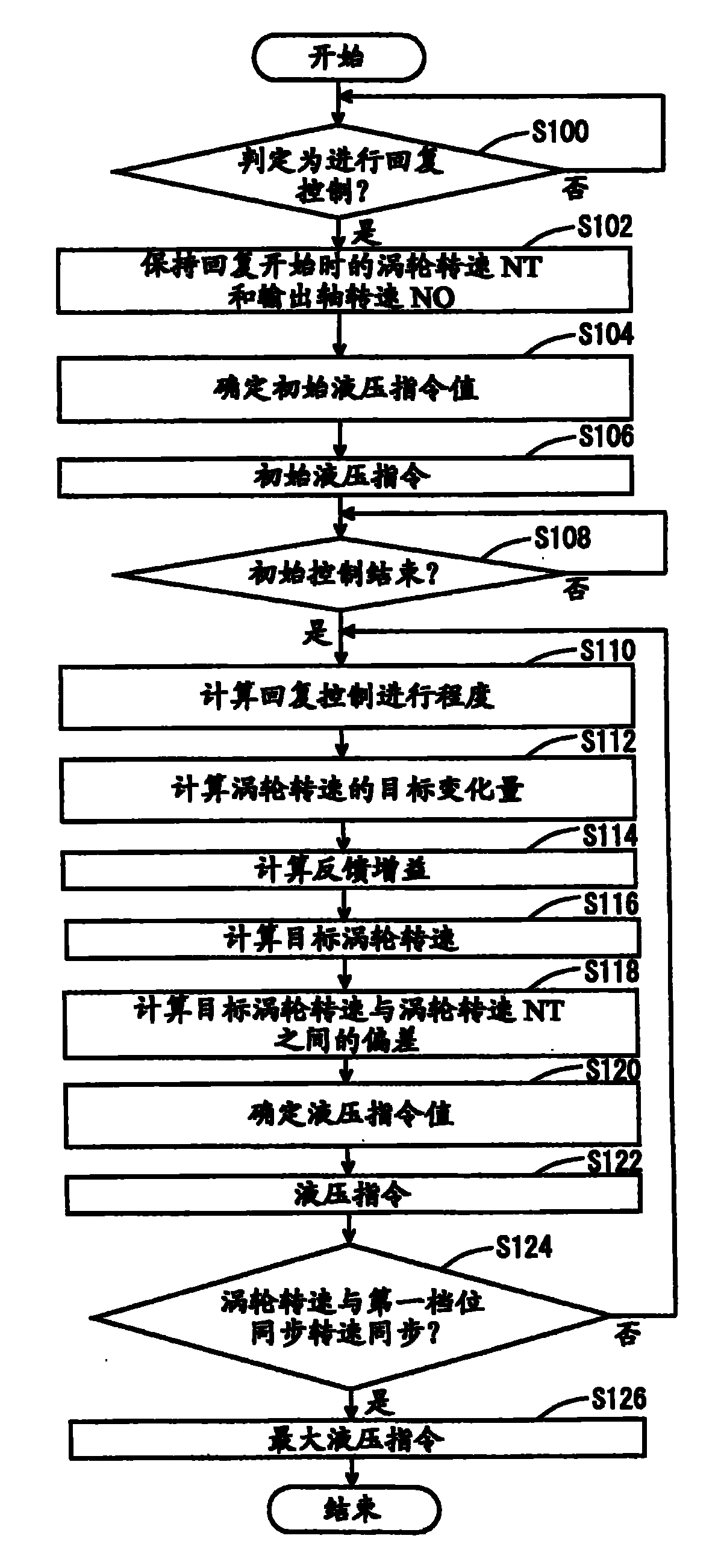
This invention relates to a vehicle controller and control method. When the initial control ends (yes in S108), the ECU executes a program including the following steps: calculating the degree of recovery control (S110); calculating the target change in turbine speed (S112); calculating the feedback gain (S114); calculating the target turbine speed (S116); calculating the deviation between the target turbine speed and the turbine speed NT (S118); determining the hydraulic command value (S120); outputting the hydraulic command (S122); and when the turbine speed is synchronized with the first gear synchronization speed (yes in S124), outputting the maximum hydraulic command (S126).
Description
技术领域technical field
本发明涉及对具有自动变速器的车辆的控制,更具体地涉及从空档控制回复的控制。This invention relates to the control of a vehicle having an automatic transmission, and more particularly to the control of reverting from neutral control.
背景技术Background technique
当车辆的自动变速器被设定为前进档位置并且车辆停止时,怠速发动机的驱动力经变矩器传递到变速器和车轮。结果,发生蠕动(creeping)。这种蠕动导致车辆停止时的较低里程。因此,在制动踏板被踩踏以操作制动器且加速器基本完全关闭而使得车辆在前进档位置停止的状态下,进行空档控制,其中在维持前进档位置的情况下变速器被设定为近乎空档状态,以便获得更好的里程。在空档控制中,在车辆起动时接合的接合元件被脱开,以使变速器到达近乎空档状态。当满足诸如为松开制动器的回复条件时,进行回复控制,其中被脱开的接合元件再次接合。When the automatic transmission of the vehicle is set to a forward position and the vehicle is stopped, the driving force of the idling engine is transmitted to the transmission and wheels via the torque converter. As a result, creeping occurs. This creep results in lower mileage when the vehicle is stopped. Therefore, neutral control is performed in a state where the brake pedal is depressed to operate the brakes and the accelerator is substantially fully closed so that the vehicle stops at a forward position in which the transmission is set to nearly neutral while maintaining the forward position status for better mileage. In neutral control, engagement elements that are engaged when the vehicle is started are disengaged to bring the transmission into a near-neutral state. When a return condition such as releasing the brake is satisfied, return control is performed in which the disengaged engagement element is engaged again.
例如,特开2005-42742号公报公开了一种能够从空档控制实现可靠回复的起动控制器。该起动控制器用于这种车辆,该车辆安装有具有在车辆起动时接合的接合元件的自动变速器。如果车辆在满足车辆状态的预定条件的同时在前进档位置停止,则实行空档控制并且接合元件被脱开,而如果满足另行确定的条件,则实行从空档控制进行的回复控制。所述起动控制器包括用于检测发动机转速的装置,和用于基于发动机转速波动来计算从空档控制回复时接合元件的接合液压的计算装置。For example, Japanese Unexamined Patent Application Publication No. 2005-42742 discloses a start controller capable of achieving reliable return from neutral control. The launch controller is used in a vehicle mounted with an automatic transmission having an engaging element engaged when the vehicle is started. If the vehicle is stopped at the forward position while satisfying predetermined conditions of the vehicle state, neutral control is performed and the engaging element is disengaged, and return control from neutral control is performed if an otherwise determined condition is satisfied. The starting controller includes means for detecting an engine speed, and calculating means for calculating an engagement hydraulic pressure of the engagement element upon return from neutral control based on fluctuations in the engine speed.
根据在所述特开公报中公开的起动控制器,考虑发动机转速波动来计算恒定待机压力。结果,提供了这样的车辆起动控制器,其能够在从空档控制回复时按照发动机状态从空档控制实现可靠回复。According to the start controller disclosed in said Laid-Open Publication, the constant standby pressure is calculated in consideration of engine speed fluctuations. As a result, there is provided a vehicle start controller capable of reliably returning from neutral control in accordance with the engine state when returning from neutral control.
但是,由于变矩器中的转矩比率变化或发动机转矩的变动,接合元件的必要液压在每次从空档状态回复时都有可能不同。因此,在从空档控制进行的回复控制中,如果该控制非常依赖于前馈控制,则不能以高的精度获得接合元件的必要接合液压。如果在从空档控制回复时供给到接合元件的液压过高或过低,便会发生在回复控制开始时突然接合或在回复控制结束时突然接合,从而可能引起冲击。However, due to torque ratio changes in the torque converter or fluctuations in engine torque, the necessary hydraulic pressure of the engagement elements may be different every return from the neutral state. Therefore, in return control from neutral control, if the control relies heavily on feedforward control, the necessary engagement hydraulic pressure of the engagement elements cannot be obtained with high accuracy. If the hydraulic pressure supplied to the engaging member is too high or too low at the time of return from neutral control, sudden engagement at the start of return control or sudden engagement at the end of return control may occur, possibly causing a shock.
在上述特开公报中,只有恒定待机压力按照发动机转速波动来改变并且其非常依赖于前馈控制。因此,该问题无法解决。In the above-mentioned Laid-Open Publication, only the constant standby pressure is changed in accordance with engine speed fluctuations and it relies heavily on feedforward control. Therefore, the problem cannot be resolved.
此外,在回复控制中,接合元件的输入轴侧与输出轴侧的相对转速减小以转换到接合状态。因此,即使在接合元件的液压被调节为使得涡轮转速变得接近目标值时,由于发动机转矩或转矩比率变化的变动,有时也不能以高的精度获得接合元件的必要接合液压。In addition, in return control, the relative rotational speed of the input shaft side and the output shaft side of the engaging element is reduced to shift to the engaged state. Therefore, even when the hydraulic pressure of the engaging elements is adjusted so that the turbine rotational speed becomes close to the target value, sometimes the necessary engaging hydraulic pressure of the engaging elements cannot be obtained with high accuracy due to fluctuations in engine torque or torque ratio variation.
发明内容Contents of the invention
本发明的目的是提供一种用于车辆的控制器和控制方法,其能够从空档控制实现快速回复而不引起任何冲击。An object of the present invention is to provide a controller and a control method for a vehicle, which can achieve quick return from neutral control without causing any shock.
根据一个方面,本发明提供了一种车辆控制器,所述车辆控制器用于设置有发动机和自动变速器的车辆,所述自动变速器具有在所述车辆起动时利用液压接合的接合元件。当所述车辆在满足车辆状态的预定条件的同时在前进档位置停止时,实行脱开所述接合元件的空档控制,以及当满足另行确定的条件时,实行接合所述接合元件的回复控制。所述自动变速器包括与所述发动机的输出轴连结的液力偶合器、与所述液力偶合器的输出轴连结的变速机构、和将液压施加给所述接合元件的液压回路。所述控制器包括:检测所述液力偶合器的涡轮转速的涡轮转速传感器,和连接到所述涡轮转速传感器的控制单元。所述控制单元在所述回复控制期间基于所述检测出的涡轮转速计算所述回复控制的进行的程度,根据所述计算出的进行的程度设定所述涡轮转速的目标变化量,以及基于所述回复控制中所述设定的目标变化量控制所述液压回路。According to one aspect, the present invention provides a vehicle controller for a vehicle provided with an engine and an automatic transmission having an engagement element that is hydraulically engaged when the vehicle is started. When the vehicle is stopped at a forward gear position while satisfying a predetermined condition of the vehicle state, neutral control for disengaging the engagement element is performed, and return control for engaging the engagement element is performed when an otherwise determined condition is satisfied . The automatic transmission includes a fluid coupling coupled to an output shaft of the engine, a transmission mechanism coupled to the output shaft of the fluid coupling, and a hydraulic circuit that applies hydraulic pressure to the engagement elements. The controller includes: a turbine speed sensor detecting a turbine speed of the fluid coupling, and a control unit connected to the turbine speed sensor. The control unit calculates a degree of progress of the return control based on the detected turbine rotational speed during the return control, sets a target change amount of the turbine rotational speed based on the calculated degree of progress, and The set target change amount in the return control controls the hydraulic circuit.
根据本发明,在从空档控制开始回复控制时(进行的程度小),在自动变速器中,接合元件处于近乎空档状态。因此,涡轮转速升高到比所述元件处于接合状态时高。随着回复控制进行(进行的程度增大),接合元件变为接合。因此,随着向接合状态的转换,由于液力偶合器的拖滞(dragging),涡轮转速降低。因此,基于涡轮转速计算出的回复控制的进行的程度对应于接合元件的变化状态,包括由发动机转矩或转矩比率的变化引起的变动。因此,当进行的程度小且状态更接近空档时,如果目标变化量的绝对值增大,则涡轮转速能更快地降低。结果,能缩短回复控制所需的时间。此外,即使在涡轮转速快速降低时,由于自动变速器处于近乎空档状态,也能抑制任何冲击的产生。此外,当目标变化量的绝对值随着回复控制的进行而变小时,涡轮转速的变动减小,并且能抑制在回复控制结束时接合冲击的产生。由于施加给接合元件的液压基于目标变化量被控制,所以与液压被控制为使得涡轮转速更接近目标值时相比,更好地反映由发动机转矩或转矩比率的变化引起的变动的液压控制变得可能。因此,能以更高的精度向接合元件施加回复控制所需的液压。因此,可提供能够从空档控制实现快速回复而不引起任何冲击的车辆控制器和车辆控制方法。According to the present invention, in the automatic transmission, the engaging elements are in a nearly neutral state when the return control is started from the neutral control (to a small extent). As a result, the turbine speed rises higher than when the elements are engaged. As the return control progresses (to an increasing extent), the engagement element becomes engaged. Therefore, with the transition to the engaged state, the turbine speed decreases due to the dragging of the fluid coupling. Therefore, the degree of progress of return control calculated based on the turbine rotational speed corresponds to the changing state of the engagement element, including fluctuations caused by changes in engine torque or torque ratio. Therefore, when the degree of progress is small and the state is closer to neutral, if the absolute value of the target change amount is increased, the turbine rotational speed can be decreased more quickly. As a result, the time required for returning control can be shortened. In addition, even when the turbo speed is rapidly reduced, any jerk is suppressed due to the automatic transmission being in a near-neutral state. Furthermore, when the absolute value of the target change amount becomes smaller as the return control proceeds, the fluctuation of the turbine rotation speed is reduced, and the occurrence of the engagement shock at the end of the return control can be suppressed. Since the hydraulic pressure applied to the engagement element is controlled based on the target variation amount, the hydraulic pressure that reflects fluctuations caused by changes in the engine torque or torque ratio better than when the hydraulic pressure is controlled so that the turbine speed is closer to the target value Control becomes possible. Therefore, hydraulic pressure required for return control can be applied to the engaging element with higher precision. Therefore, it is possible to provide a vehicle controller and a vehicle control method capable of achieving quick return from neutral control without causing any shock.
优选地,随着所述进行的程度变得越高,所述控制单元将所述目标变化量的绝对值设定得越小。Preferably, the control unit sets an absolute value of the target change amount to be smaller as the degree of progress becomes higher.
根据本发明,当进行的程度小且状态更接近空档时,通过将目标变化量的绝对值设定得更大,能更快地降低涡轮转速。结果,能缩短回复控制所需的时间。此外,即使在涡轮转速快速降低时,由于自动变速器处于近乎空档状态,也能抑制任何冲击的产生。或者,通过随着回复控制的进行将目标变化量的绝对值设定得越小,涡轮转速的变动被抑制,并且能防止在回复控制结束时产生接合冲击。因此,即使存在发动机转矩或转矩比率变化的任何变动,也能从空档控制实现快速回复而不引起任何冲击。According to the present invention, when the degree of progress is small and the state is closer to neutral, by setting the absolute value of the target change amount larger, the turbine rotational speed can be decreased more quickly. As a result, the time required for returning control can be shortened. In addition, even when the turbo speed is rapidly reduced, any jerk is suppressed due to the automatic transmission being in a near-neutral state. Alternatively, by setting the absolute value of the target change amount smaller as the return control progresses, fluctuations in the turbine rotational speed are suppressed, and engagement shock can be prevented from occurring at the end of the return control. Therefore, even if there is any variation in engine torque or torque ratio variation, quick return from neutral control can be achieved without causing any jerk.
更优选地,当所述进行的程度进行到超过预定程度时,所述控制单元将所述目标变化量的所述绝对值设定为比上次设定的所述目标变化量的绝对值小的预定值。More preferably, when the degree of progress exceeds a predetermined degree, the control unit sets the absolute value of the target change amount to be smaller than the absolute value of the target change amount set last time predetermined value.
根据本发明,当进行的程度小且状态更接近空档时,目标变化量的绝对值被设定得更大,从而能更快地降低涡轮转速。结果,能缩短回复控制所需的时间。此外,即使在涡轮转速快速降低时,由于自动变速器处于近乎空档状态,也能抑制任何冲击的产生。或者,随着回复控制的进行将目标变化量的绝对值设定得越小。结果,涡轮转速的变动被抑制,并且能防止在回复控制结束时产生接合冲击。因此,即使存在发动机转矩或转矩比率变化的任何变动,也能从空档控制实现快速回复而不引起任何冲击。According to the present invention, when the degree of progress is small and the state is closer to neutral, the absolute value of the target change amount is set larger, so that the turbine rotational speed can be decreased more quickly. As a result, the time required for returning control can be shortened. In addition, even when the turbo speed is rapidly reduced, any jerk is suppressed due to the automatic transmission being in a near-neutral state. Alternatively, the absolute value of the target change amount is set to be smaller as the return control proceeds. As a result, fluctuations in the turbine rotational speed are suppressed, and engagement shock can be prevented from occurring at the end of return control. Therefore, even if there is any variation in engine torque or torque ratio variation, quick return from neutral control can be achieved without causing any jerk.
更优选地,所述控制单元基于所述设定的目标变化量设定目标涡轮转速,以及控制所述液压回路,使得基于所述目标涡轮转速与所述检测出的涡轮转速之间的差和基于所述目标变化量与所述涡轮转速的变化量之间的差确定的液压被施加给所述接合元件。More preferably, the control unit sets a target turbine rotation speed based on the set target change amount, and controls the hydraulic circuit so that based on the sum of the difference between the target turbine rotation speed and the detected turbine rotation speed, A hydraulic pressure determined based on a difference between the target change amount and the change amount of the turbine rotational speed is applied to the engaging element.
根据本发明,所述液压回路被控制成,使得基于所述目标涡轮转速与所述检测出的涡轮转速之间的差和基于所述目标变化量与所述涡轮转速的变化量之间的差确定的液压被施加给所述接合元件。特别地,目标变化量根据回复控制的进行的程度被设定,且由此能使回复控制中涡轮转速的变化状态在每次进行回复控制时都被设定为相同的状态,而与发动机转矩或转矩比率的任何变化无关。因此,在每次进行回复控制时都能在防止产生任何冲击的同时从空档控制实现快速回复。According to the present invention, the hydraulic circuit is controlled so that based on the difference between the target turbine speed and the detected turbine speed and based on the difference between the target change amount and the change amount of the turbine speed A determined hydraulic pressure is applied to the engaging element. In particular, the target change amount is set in accordance with the degree of progress of the return control, and thus the state of change in the turbine rotational speed in the return control can be set to the same state every time the return control is performed, and is not related to the engine speed. Any change in torque or torque ratio is irrelevant. Therefore, quick return from neutral control can be achieved while preventing any shock every time return control is performed.
更优选地,所述控制单元使用当前的涡轮转速作为起点基于所述目标变化量设定所述目标涡轮转速。More preferably, the control unit sets the target turbine rotation speed based on the target change amount using a current turbine rotation speed as a starting point.
根据本发明,使用当前的涡轮转速作为起点,基于目标变化量设定目标涡轮转速。目标变化量根据回复控制的进行的程度被设定,且因此在回复控制中接合元件从脱开状态到接合状态的转换状态在每次进行回复控制时都能被设定为相同的状态,而与发动机转矩或转矩比率的任何变化无关。According to the present invention, using the current turbine rotational speed as a starting point, the target turbine rotational speed is set based on the target change amount. The target change amount is set according to the degree of progress of the return control, and thus the switching state of the engagement element from the disengaged state to the engaged state in the return control can be set to the same state every time the return control is performed, while Independent of any changes in engine torque or torque ratio.
更优选地,所述控制单元使用所述目标变化量被设定的时点的涡轮转速作为起点基于所述目标变化量设定所述目标涡轮转速。More preferably, the control unit sets the target turbine rotation speed based on the target variation amount using, as a starting point, a turbine rotation speed at a time point when the target variation amount is set.
根据本发明,使用设定目标变化量时的涡轮转速作为起点,基于目标变化量设定目标涡轮转速。目标变化量根据回复控制的进行的程度被设定,且因此在回复控制中接合元件从脱开状态到接合状态的转换状态在每次进行回复控制时都能被设定为相同的状态,而与发动机转矩或转矩比率的任何变化无关。According to the present invention, the target turbine speed is set based on the target change amount, using the turbine speed when the target change amount is set as a starting point. The target change amount is set according to the degree of progress of the return control, and thus the switching state of the engagement element from the disengaged state to the engaged state in the return control can be set to the same state every time the return control is performed, while Independent of any changes in engine torque or torque ratio.
更优选地,所述控制器还包括连接到所述控制单元和检测所述变速机构的输出轴转速的输出轴转速传感器。所述控制单元控制所述液压回路,使得当所述检测出的输出轴转速和所述车辆起动时的变速比的乘积与所述检测出的涡轮转速同步时,最大的液压被施加给所述接合元件。More preferably, the controller further includes an output shaft rotation speed sensor connected to the control unit and detecting an output shaft rotation speed of the transmission mechanism. The control unit controls the hydraulic circuit so that the maximum hydraulic pressure is applied to the Joint element.
根据本发明,在作为输出轴转速和车辆起动时的变速比的乘积的值与所述检测出的涡轮转速同步的时点,接合元件的输入轴侧和输出轴侧之间的相对转速达到基本为零,并且液压回路被控制为使得最大的液压被施加。因此,能在防止产生任何冲击的同时将接合元件设定到充分接合状态。According to the present invention, the relative rotational speed between the input shaft side and the output shaft side of the engagement element reaches substantially is zero, and the hydraulic circuit is controlled such that maximum hydraulic pressure is applied. Therefore, it is possible to set the engaging elements to the fully engaged state while preventing any shock from being generated.
更优选地,所述控制单元通过将所述检测出的涡轮转速除以所述回复控制开始时检测出的所述涡轮转速来计算所述进行的程度。More preferably, the control unit calculates the degree of progress by dividing the detected turbine rotation speed by the turbine rotation speed detected at the start of the return control.
根据本发明,在从空档控制进行的回复控制中,当接合元件从近乎空档状态到达接合状态时,液力偶合器拖滞,且因此涡轮转速随着接合元件的接合而逐渐降低。因此,通过将当前的涡轮转速除以回复控制开始时检测出的涡轮转速,能计算出回复控制的进行的程度。According to the present invention, in return control from neutral control, when the engagement element reaches the engagement state from the nearly neutral state, the fluid coupling drags, and thus the turbine rotational speed gradually decreases with engagement of the engagement element. Therefore, the degree of progress of the return control can be calculated by dividing the current turbine rotation speed by the turbine rotation speed detected at the start of the return control.
更优选地,所述控制单元通过将所述接合元件的输入轴侧与输出轴侧之间的第一转速差除以所述回复控制开始时所述接合元件的所述输入轴侧与所述输出轴侧之间的第二转速差来计算所述进行的程度。More preferably, the control unit divides the first rotational speed difference between the input shaft side and the output shaft side of the engagement element by the difference between the input shaft side and the output shaft side of the engagement element when the return control starts. The second rotational speed difference between the output shaft sides is used to calculate the degree of progress.
根据本发明,在从空档控制进行的回复控制中,当接合元件从近乎空档状态到达接合状态时,液力偶合器拖滞,且因此涡轮转速随着接合元件的接合而逐渐降低。因此,通过将所述第一转速差除以所述第二转速差,能计算出回复控制的进行的程度。According to the present invention, in return control from neutral control, when the engagement element reaches the engagement state from the nearly neutral state, the fluid coupling drags, and thus the turbine rotational speed gradually decreases with engagement of the engagement element. Therefore, by dividing the first rotational speed difference by the second rotational speed difference, the degree of progress of the return control can be calculated.
更优选地,所述第一转速差指的是所述检测出的涡轮转速与所述变速机构的所述输出轴转速和所述车辆起动时的变速比的乘积之间的差。所述第二转速差指的是在所述回复控制开始时,所述检测出的涡轮转速与所述变速机构的所述输出轴转速和所述车辆起动时的所述变速比的乘积之间的差。More preferably, the first rotational speed difference refers to a difference between the detected turbine rotational speed and the product of the rotational speed of the output shaft of the transmission mechanism and the gear ratio at the time of starting the vehicle. The second rotation speed difference refers to a difference between the detected turbine rotation speed and the product of the output shaft rotation speed of the transmission mechanism and the transmission ratio at the time of starting the vehicle at the start of the return control. poor.
根据本发明,在从空档控制进行的回复控制中,当接合元件从近乎空档状态到达接合状态时,液力偶合器拖滞,且因此涡轮转速随着接合元件的接合而逐渐降低。因此,通过将当前的涡轮转速与作为输出轴转速和车辆起动时的变速比的乘积的值之间的差除以在回复控制开始时的所检测出的涡轮转速与作为变速机构的输出轴转速和车辆起动时的变速比的乘积的值之间的差,能计算出回复控制的进行的程度。According to the present invention, in return control from neutral control, when the engagement element reaches the engagement state from the nearly neutral state, the fluid coupling drags, and thus the turbine rotational speed gradually decreases with engagement of the engagement element. Therefore, by dividing the difference between the current turbine rotational speed and a value that is the product of the output shaft rotational speed and the gear ratio at the start of the vehicle by the detected turbine rotational speed at the start of return control by the output shaft rotational speed of the transmission mechanism The degree of progress of the return control can be calculated from the difference between the value of the product and the value of the product of the gear ratio at the time of vehicle startup.
从下面在结合附图时给出的对本发明的详细说明中可更清楚地看到本发明的上述和其它目的、特征、方面及优点。The above and other objects, features, aspects and advantages of the present invention will become more apparent from the following detailed description of the invention given in conjunction with the accompanying drawings.
附图说明Description of drawings
图1示意性地示出车辆的传动系的构型。FIG. 1 schematically shows the configuration of a drive train of a vehicle.
图2是自动变速器的工作表。Figure 2 is a worksheet for an automatic transmission.
图3是作为根据第一实施例的车辆控制器的ECU的功能框图。Fig. 3 is a functional block diagram of an ECU as a vehicle controller according to the first embodiment.
图4是示出由作为根据第一实施例的车辆控制器的ECU执行的程序的控制结构的流程图。4 is a flowchart showing a control structure of a program executed by the ECU as the vehicle controller according to the first embodiment.
图5是示出作为根据第一实施例的车辆控制器的ECU的操作的时序图。FIG. 5 is a timing chart showing the operation of the ECU as the vehicle controller according to the first embodiment.
图6是示出由作为根据第二实施例的车辆控制器的ECU执行的程序的控制结构的流程图。6 is a flowchart showing a control structure of a program executed by the ECU as the vehicle controller according to the second embodiment.
图7是示出作为根据第二实施例的车辆控制器的ECU的操作的时序图。Fig. 7 is a timing chart showing the operation of the ECU as the vehicle controller according to the second embodiment.
具体实施方式Detailed ways
下面将参照附图说明本发明的实施例。在以下说明中,相同的部件用相同的附图标记表示。它们的名称和功能也相同。因此,将不重复其详细说明。Embodiments of the present invention will be described below with reference to the drawings. In the following description, the same components are denoted by the same reference numerals. Their names and functions are also the same. Therefore, its detailed description will not be repeated.
<第一实施例><First embodiment>
参照图1,将描述安装有根据本实施例的车辆控制器的车辆的传动系。根据本实施例的车辆控制器具体由图1所示的ECU(电子控制单元)1000来实现。Referring to FIG. 1 , a power train of a vehicle mounted with a vehicle controller according to the present embodiment will be described. The vehicle controller according to the present embodiment is realized specifically by an ECU (Electronic Control Unit) 1000 shown in FIG. 1 .
如图1所示,车辆的传动系包括发动机100、自动变速器320和ECU1000。自动变速器320包括作为液力偶合器的变矩器200和由行星齿轮装置形成的变速机构300。As shown in FIG. 1 , the power train of a vehicle includes an
尽管在本实施例中自动变速器320被描述为齿轮式自动变速器,但是其也可以是具有至少在车辆起动时接合的摩擦接合元件的任何自动变速器。例如,可使用具有利用带来连续改变变速比的变速机构的无级自动变速器。Although the
发动机100的输出轴连接到变矩器200的输入轴。发动机100和变矩器200由旋转轴连结。因此,发动机100的由发动机转速传感器400检测的输出轴转速NE(下文中称作发动机转速NE)与变矩器200的输入轴转速(泵转速)相同。发动机转速传感器400向ECU 1000传递表示所检测出的发动机转速NE的信号。An output shaft of
变矩器200包括用于使输入轴与输出轴直接连结的锁止离合器210、输入轴侧的泵轮220、输出轴侧的涡轮230和具有单向离合器250并具有转矩放大功能的导轮240。变矩器200和变速机构300由旋转轴连接。The
变矩器200的输出轴转速NT(下文中称作涡轮转速NT)由涡轮转速传感器410检测。涡轮转速传感器410向ECU 1000传递表示所检测出的涡轮转速NT的信号。An output shaft rotational speed NT (hereinafter referred to as turbine rotational speed NT) of
此外,变速机构300(自动变速器320)的输出轴转速NOUT由输出轴转速传感器420检测。输出轴转速传感器420向ECU 1000传递所检测出的输出轴转速NOUT。Furthermore, output shaft rotation speed NOUT of transmission mechanism 300 (automatic transmission 320 ) is detected by output shaft
来自涡轮转速传感器410的表示涡轮转速NT的信号、来自输出轴转速传感器420的表示输出轴转速NOUT的信号和来自发动机转速传感器400的表示发动机转速NE的信号输入到如此控制传动系的ECU 1000。A signal indicative of turbine rotational speed NT from turbine
这些转速传感器布置成与齿轮的齿相对以进行转速检测,设置在变矩器200的输入轴、变矩器200的输出轴和变速机构300的输出轴上。这些转速传感器能够检测出变矩器200的输入轴、变矩器200的输出轴和变速机构300的输出轴的甚至稍许转动,并且通常,这些传感器使用磁致电阻元件并且被称作半导体传感器。These rotational speed sensors are arranged opposite to the teeth of the gears for rotational speed detection, and are provided on the input shaft of the
此外,制动灯开关430在驾驶员操作制动踏板达预定量时向ECU 1000传递表示开启状态的信号。因此,表示制动器开启的信号从制动灯开关430输入到ECU 1000。In addition, the
在本实施例中,变速机构300由多个行星齿轮装置和多个摩擦接合元件构成。所述多个摩擦接合元件包括离合器元件C1至C4和制动器元件B1至B4。In the present embodiment, the
变速机构300的所述多个摩擦接合元件的接合力由从液压回路260施加的液压来调节。液压回路260包括油泵、各种螺线管(电磁线圈)、和油通路(都未示出)。在液压回路260中,各个螺线管基于来自ECU 1000的螺线管控制信号而工作,由此施加给所述多个摩擦接合元件之中的预定组合的摩擦接合元件的液压被调节。如图2的自动变速器320的工作表所示,所述预定组合的摩擦接合元件对应于选定的变速位置或变速比。这样,ECU 1000控制液压回路260的各个螺线管及由此控制要施加给所述多个摩擦接合元件的液压。Engagement forces of the plurality of frictional engagement elements of the
图2的工作表示出作为摩擦元件的离合器元件(图中的C1至C4)、制动器元件(B1至B4)和单向离合器元件(F0至F3)在哪些档位下接合和脱开。在车辆起动时使用的第一档位下,离合器元件C1与单向离合器元件F0和F3接合。在这些离合器元件之中,具体地,离合器元件C1被称作输入离合器310。输入离合器310也被称作前进档离合器或前进离合器,并且如从图2的工作表可见,除了驻车(P)位置、倒档(R)位置和空档(N)位置之外,其总是被用在要获得使车辆向前运动的变速比时的接合状态下。The working diagram of Fig. 2 shows in which gears the clutch elements (C1 to C4 in the figure), the brake elements (B1 to B4) and the one-way clutch elements (F0 to F3) as friction elements are engaged and disengaged. In first gear, which is used when the vehicle is launched, clutch element C1 is engaged with one-way clutch elements F0 and F3. Among these clutch elements, specifically, the clutch element C1 is referred to as an
如果判定为变速器处于前进档(D)位置并且车辆处于停止状态且满足预定条件(加速器关闭,制动器开启,制动主缸压力不低于规定值且车速不高于规定值),则输入离合器310被脱开并被设定到规定的打滑状态、近乎空档状态。这种控制被称作空档控制。此外,当实行空档控制时,输入离合器310被脱开并且制动器元件B2被设定到接合状态,以限制车辆的向前/向后运动。当满足另行确定的回复条件时,实行从空档控制进行的回复控制,从而输入离合器310接合且制动器元件B2被脱开。“回复条件”可以是未满足上述预定条件。If it is determined that the transmission is in the forward gear (D) position and the vehicle is stopped and predetermined conditions are met (accelerator off, brake on, brake master cylinder pressure not lower than a specified value and vehicle speed not higher than a specified value), the
在如上所述地构造的车辆中,本发明的特征在于,在从空档控制进行的回复控制中,ECU 1000基于涡轮转速NT计算回复控制的进行的程度(下文中称作回复控制进行程度),基于所计算出的回复控制进行程度设定涡轮转速的目标变化量,以及基于回复控制中所设定的目标变化量控制液压回路。In the vehicle constructed as described above, the present invention is characterized in that, in return control from neutral control,
具体地,ECU 1000将当前输入离合器310的输入轴侧与输出轴侧之间的转速差(1)除以回复控制开始时输入离合器310的输入轴侧与输出轴侧之间的转速差(2),由此计算回复控制进行程度。Specifically, the
此外,随着所计算出的回复控制进行程度变得越高,ECU 1000将目标变化量的绝对值设定得越小。在本实施例中,当回复控制进行程度进行并超过预定程度时,ECU 1000将目标变化量的绝对值设定为比上次设定的目标变化量的绝对值小的预定值。In addition,
在本实施例中,涡轮转速NT的朝向减小侧的变化量将被描述为正值。因此,随着回复控制进行程度变得越高,ECU 1000将目标变化量设定得越小。In the present embodiment, the amount of change of the turbine rotational speed NT toward the decreasing side will be described as a positive value. Therefore,
图3是作为根据本实施例的车辆控制器的ECU 1000的功能框图。ECUFIG. 3 is a functional block diagram of
1000包括输入接口(下文中表示为输入I/F)350、工作单元450、存储单元550和输出接口(下文中表示为输出I/F)650。1000 includes an input interface (hereinafter denoted as input I/F) 350 , a working
输入I/F 350接收来自发动机转速传感器400的发动机转速信号、来自涡轮转速传感器410的涡轮转速信号、来自输出轴转速传感器420的输出轴转速信号和来自制动灯开关430的制动灯开关信号,并将这些信号传递给工作单元450。作为制动灯开关信号的替换或附加,输入I/F 350可接收主缸压力信号、加速踏板位置信号和车速信号中的至少一个。The input I/
工作单元450包括回复控制判定单元452、转速保持单元454、初始控制单元456、进行程度计算单元458、目标值计算单元460、液压指令值确定单元462、液压控制信号输出单元464、同步判定单元466和终止控制单元468。The working
回复控制判定单元452判定是否要实行从空档控制进行的回复控制。具体地,当满足上述回复条件时,回复控制判定单元452判定为要实行回复控制。当判定为要实行回复控制时,回复控制判定单元452可使回复控制实行标记置位。Return
当判定为要实行回复控制时,转速保持单元454保持回复控制开始时的涡轮转速NT。具体地,当判定为要实行回复控制时,转速保持单元454将从涡轮转速传感器410接收的涡轮转速NT保持在存储单元550中。When it is determined that the return control is to be executed, the rotational
此外,当判定为要实行回复控制时,转速保持单元454保持回复控制开始时的输出轴转速NO。具体地,当判定为要实行回复控制时,转速保持单元454将从输出轴转速传感器420接收的输出轴转速NO保持在存储单元550中。Furthermore, when it is determined that return control is to be executed, the rotational
当回复控制实行标记被置位时,转速保持单元454可将回复控制开始时的涡轮转速NT和输出轴转速NO存储在存储单元550中。When the return control execution flag is set, the rotation
当判定为要实行回复控制时,初始控制单元456实行初始控制。在初始控制中,初始控制单元456将与预定的液压指令值对应的液压控制信号经输出I/F 650输出到与液压回路260的输入离合器310对应的螺线管。When it is determined that return control is to be executed, the
当例如回复控制实行标记被置位时,初始控制单元456可实行初始控制。此外,当在实行初始控制后经过预定时间时,初始控制单元456结束初始控制。The
进行程度计算单元458计算回复控制实行时的回复控制进行程度。进行程度计算单元458通过将输入离合器310的输入轴侧与输出轴侧之间的转速差(1)除以回复控制开始时输入离合器310的输入轴侧与输出轴侧之间的转速差(2)来计算回复控制进行程度。The degree of
在本实施例中,进行程度计算单元458从当前的涡轮转速NT与作为当前的输出轴转速NO和车辆起动时的变速比的乘积的值之间的差来计算转速差(1)。此外,进行程度计算单元458从由转速保持单元454保持的涡轮转速NT与作为输出轴转速NO和车辆起动时的变速比的乘积的值来计算转速差(2)。In the present embodiment, the degree of
在本实施例中,车辆起动时的变速比例如是与第一档位对应的变速比。如果自动变速器320是无级变速器,则车辆起动时的变速比例如是与最减速的状态对应的变速比。In this embodiment, the gear ratio when the vehicle is started is, for example, the gear ratio corresponding to the first gear. If
此外,进行程度计算单元458可在回复控制实行标记被置位后在回复控制开始时的涡轮转速NT和输出轴转速NO被保持时计算回复控制进行程度。Further, the degree of
计算回复控制进行程度的方法不限于上述方法,并且例如,进行程度计算单元458可通过将当前的涡轮转速NT除以由转速保持单元454保持的回复控制开始时的涡轮转速NT来计算回复控制进行程度。The method of calculating the degree of progress of the return control is not limited to the above method, and for example, the progress
在本实施例中,随着输入离合器310接合,回复控制进行程度的值变得更接近零。具体地,当输入离合器310完全接合时,转速差(1)达到基本为零,并且回复控制进行程度达到零。In the present embodiment, as the
在本实施例中,回复控制进行程度也可表示为{1-(转速差(1)/转速差(2))}×100(%)。此处,100%的回复控制进行程度对应于转速差(1)达到基本为零且输入离合器310完全接合的状态。In this embodiment, the progress degree of the recovery control can also be expressed as {1-(rotational speed difference (1)/rotational speed difference (2))}×100(%). Here, 100% return control progress corresponds to a state where the rotational speed difference (1) reaches substantially zero and the
目标值计算单元460根据所计算出的回复控制进行程度设定涡轮转速NT的目标变化量。目标值计算单元460将涡轮转速NT的目标变化量设定为使得其值随着回复控制进行程度向前进侧变化(在本实施例中,随着回复控制进行程度的值减小)而变小。The target
具体地,当回复控制进行程度达到预定程度或更低时,目标值计算单元460将目标变化量设定为比上次设定的目标变化量小的预定值。Specifically, when the degree of progress of the return control reaches a predetermined level or lower, the target
此外,目标值计算单元460基于所设定的目标变化量来设定目标涡轮转速。在本实施例中,目标值计算单元460使用当前的涡轮转速NT作为起点基于目标变化量来设定目标涡轮转速。具体地,目标值计算单元460基于所设定的目标变化量和直到用于确定下一液压指令值的计算实行之前的时间(例如,采样时间)来设定目标涡轮转速。Furthermore, the target
液压指令值确定单元462基于目标涡轮转速与涡轮转速NT之差、目标变化量与涡轮转速NT的实际变化量之差和回复控制进行程度来确定施加给输入离合器310的液压的指令值。The hydraulic pressure command
在本实施例中,液压指令值确定单元462基于目标变化量和实际变化量之间的偏差和基于回复控制进行程度来计算反馈增益。例如,随着目标变化量和实际变化量之间的偏差变大,液压指令值确定单元462增大反馈增益。此外,随着回复控制进行程度向前进侧变化(随着回复控制进行程度的值减小),液压指令值确定单元462减小反馈增益。也能将表示目标变化量和实际变化量之间的偏差、回复控制进行程度和反馈增益之间的关系的图谱、公式、表格等预先存储在存储单元550中。In the present embodiment, the hydraulic pressure command
液压指令值确定单元462基于目标涡轮转速和涡轮转速NT之间的偏差以及所计算出的反馈增益来确定液压指令值。The hydraulic pressure command
液压指令值确定单元462可基于目标变化量和实际变化量之间的偏差以及基于回复控制进行程度来计算反馈增益的修正系数。或者,液压指令值确定单元462可基于目标涡轮转速和涡轮转速NT之间的偏差、预定的反馈增益和所计算出的修正系数来确定液压指令值。The hydraulic pressure command
液压控制信号输出单元464产生与所确定的液压指令值对应的液压控制信号,并将所产生的液压控制信号经输出I/F 650输出到与输入离合器310对应的螺线管。The hydraulic control
同步判定单元466判定输入离合器310的输入轴侧与输出轴侧是否同步。具体地,同步判定单元466判定涡轮转速NT与作为输出轴转速NO和车辆起动时的变速比(例如,第一档位的传动比)的乘积的值是否同步。如果涡轮转速NT与作为输出轴转速NO和变速比的乘积的值之间的差的绝对值不大于预定值,则同步判定单元466判定为这两者同步。Synchronization determining means 466 determines whether or not the input shaft side and the output shaft side of the
当判定为涡轮转速NT与作为输出轴转速NO和变速比的乘积的值同步时,同步判定单元466可使同步判定标记置位。
当涡轮转速NT与作为输出轴转速NO和变速比的乘积的值同步时,终止控制单元468实行终止控制。具体地,终止控制单元468将液压回路260控制为使得最大的液压被施加给输入离合器310。终止控制单元468将与最大的液压指令值对应的液压控制信号经输出I/F 650输出到与输入离合器310对应的螺线管。
终止控制单元468可在同步判定标记被置位时实行终止控制。The
在本实施例中,回复控制判定单元452、转速保持单元454、初始控制单元456、进行程度计算单元458、目标值计算单元460、液压指令值确定单元462、液压控制信号输出单元464、同步判定单元466和终止控制单元468全都被描述为由作为工作单元450的CPU执行存储在存储单元550中的程序而实现的软件功能。这些单元也可由硬件实现。所述程序记录在记录介质上并安装在车辆上。In this embodiment, the return
存储单元550存储各种信息、程序、阈值、图谱等,并且数据由工作单元450按照需要读取或存储。The
下面将参照图4说明由作为根据本实施例的车辆控制器的ECU 1000执行的程序的控制结构。The control structure of the program executed by
在步骤(下文中“步骤”将表示为“S”)100中,ECU 1000判定是否要实行从空档控制进行的回复控制。如果判定为要实行从空档控制进行的回复控制(在S100中为是),则处理程序转到S102。否则(在S100中为否),处理程序返回S100。In step (hereinafter "step" will be denoted as "S") 100,
在S102中,ECU 1000保持回复控制开始时的输出轴转速NO和涡轮转速NT。在S104中,ECU 1000确定初始液压指令值。在S106中,ECU1000将与所确定的初始液压指令值对应的液压控制信号输出到液压回路260。In S102,
在S108中,ECU 1000判定初始控制是否已终止。如果初始控制已终止(在S108中为是),则处理程序转到S110。否则(在S103中为否),处理程序返回S108。In S108,
在S110中,ECU 1000计算回复控制进行程度。在S112中,根据所计算出的回复控制进行程度计算涡轮转速NT的目标变化量。在S114中,ECU 1000基于所计算出的回复控制进行程度和基于目标变化量与实际变化量之间的偏差来计算反馈增益。In S110,
在S116中,ECU 1000基于所计算出的目标变化量来计算目标涡轮转速。在S118中,ECU 1000计算目标涡轮转速与涡轮转速NT之间的偏差。在S120中,ECU 1000基于所计算出的反馈增益和基于目标涡轮转速与涡轮转速之间的偏差来确定液压指令值。在S122中,ECU 1000将与所确定的液压指令值对应的液压控制信号输出到液压回路260。In S116,
在S124中,ECU 1000判定涡轮转速NT是否与第一档位同步的转速(即,通过将输出轴转速NO乘以第一档位的变速比所获得的值)同步。如果涡轮转速NT与第一档位同步转速同步(在S124中为是),则处理程序转到S126。如果不同步(在S124中为否),则处理程序返回S110。In S124,
在S126中,ECU 1000将与液压指令值的最大值对应的液压控制信号输出到液压回路260。In S126,
参照图5说明作为根据本实施例的车辆控制器的ECU 1000的基于上述结构和流程图的操作。The operation of
例如,假定由于车辆满足用于实行空档控制的预定条件,空档控制已实行。此处,自动变速器320处于近乎空档状态。由于驾驶员未操作加速器,所以发动机处于怠速状态。For example, assume that neutral control has been carried out because the vehicle satisfies predetermined conditions for carrying out neutral control. Here,
当在时刻T(0)例如由于驾驶员减小在制动踏板上的踩踏量或松开制动踏板而满足了回复条件时,判定为实行回复控制(在S100中为是)。如果判定为实行回复控制,则回复控制开始时的输出轴转速NO和涡轮转速NT被保持(S102)。车辆处于停止状态,且因此输出轴转速NO基本为零。When the return condition is satisfied at time T(0), for example, by the driver reducing the amount of depression on the brake pedal or releasing the brake pedal, it is determined that the return control is executed (YES in S100 ). If it is determined that return control is executed, the output shaft rotational speed NO and turbine rotational speed NT at the start of return control are held (S102). The vehicle is at a standstill, and thus the output shaft rotational speed NO is substantially zero.
此外,在时刻T(0),实行针对输入离合器310的初始控制。结合输入离合器310的接合控制,还实行制动器元件B2的脱开控制。具体地,初始液压指令值P(1)被确定(S104),并且与初始液压指令值P(1)对应的液压控制信号被输出到液压回路260(S106)。因此,如图5所示,在时刻T(0),液压指令值从P(0)到P(1)阶梯式地升高。通过实行初始控制,减小了输入离合器310的游隙(backlash)。在游隙减小后,输入离合器310开始接合,且因此涡轮转速NT在初始控制的后半部分开始降低。Also, at time T(0), initial control for
如果在从时刻T(0)起经过规定时间后的时刻T(1)判定为初始控制结束(在S108中为是),则液压指令值从P(1)降低到被设定为反馈控制的初始值的液压指令值P(2)。然后,计算回复控制进行程度(S110)。If it is determined at time T(1) after a predetermined time has elapsed from time T(0) that the initial control has ended (YES in S108), the hydraulic pressure command value is lowered from P(1) to the value set for feedback control. The hydraulic command value P(2) of the initial value. Then, the return control progress degree is calculated (S110).
如从图5中的虚线可见,从所计算出的回复控制进行程度计算涡轮转速的目标变化量(S112)。基于所计算出的回复控制进行程度和目标变化量,计算反馈增益(S114)。此外,基于所计算出的目标变化量,计算目标涡轮转速(S116)。计算所计算出的目标涡轮转速与涡轮转速NT之间的偏差(S118)。基于所计算出的反馈增益和所计算出的目标涡轮转速与涡轮转速NT之间的偏差,确定液压指令值(S120)。As can be seen from the dotted line in FIG. 5 , the target change amount of the turbine rotational speed is calculated from the calculated return control progress degree ( S112 ). Based on the calculated return control progress degree and target change amount, a feedback gain is calculated (S114). Furthermore, based on the calculated target change amount, a target turbine rotational speed is calculated (S116). A deviation between the calculated target turbine rotation speed and turbine rotation speed NT is calculated (S118). Based on the calculated feedback gain and the calculated deviation between the target turbine rotation speed and the turbine rotation speed NT, a hydraulic command value is determined (S120).
当确定了液压指令值时,与所确定的液压指令值对应的液压控制信号被输出(S122)。如果涡轮转速NT未与第一档位同步转速同步(在S124中为否),则再次计算回复控制进行程度(S110)。这样,输入离合器310的接合力随时间增大,且因此涡轮转速NT由于变矩器200的拖滞而降低。When the hydraulic pressure command value is determined, a hydraulic pressure control signal corresponding to the determined hydraulic pressure command value is output (S122). If the turbine rotational speed NT is not synchronized with the first gear synchronous rotational speed (NO in S124), the return control progress degree is calculated again (S110). In this way, the engagement force of the
在反馈控制的从回复控制开始直到回复控制进行程度达到50%(0.5)的初期(时刻T(1)到T(2)),自动变速器320处于近乎空档状态,且因此,作为涡轮转速NT的目标变化量的绝对值,相比于比初期更晚的时期,更大的值被设定。因此,在回复控制的整个期间,涡轮转速在初期以最高的速率降低。At the initial stage (time T(1) to T(2)) of the feedback control from the start of the return control until the degree of progress of the return control reaches 50% (0.5), the
在反馈控制的从回复控制进行程度达到50%(0.5)时起直到其达到80%(0.2)的中期(时刻T(2)到T(3)),目标变化量比在初期更小且随着回复控制的进行而减小。因此,涡轮转速NT平缓地变化。In the mid-stage (time T(2) to T(3)) of the feedback control from when the feedback control progress reaches 50% (0.5) until it reaches 80% (0.2), the target change amount is smaller than that at the initial stage and changes with Decreases as recovery control proceeds. Therefore, the turbine rotational speed NT changes smoothly.
此外,在反馈控制的从回复控制进行程度达到80%(0.2)时起直到终止控制开始的后期(时刻T(3)到T(5)),目标变化量基本为零。因此,涡轮转速仍更平缓地变化。当车辆在时刻T(4)开始移动时,输出轴转速NO升高,且因此第一档位同步转速也开始升高。此外,输出轴转速NO的升高减小变矩器200的拖滞程度,且因此涡轮转速也升高。当涡轮转速与第一档位同步转速在时刻T(5)同步时(在S124中为是),实行终止控制。具体地,与液压指令值的最大值对应的液压控制信号被输出到液压回路260(S126)。In addition, the target change amount is substantially zero in the feedback control from when the return control progress reaches 80% (0.2) until the end control starts (time T(3) to T(5)) at the later stage. Therefore, the turbine speed still varies more gradually. When the vehicle starts moving at time T(4), the output shaft rotational speed NO rises, and thus the first-gear synchronous rotational speed also starts to rise. In addition, an increase in the output shaft rotational speed NO reduces the degree of drag of the
根据本实施例的车辆控制器如上所述地工作,并且在自动变速器中,在从空档控制进行的回复控制开始时(进行的程度小),输入离合器处于接近空档状态的状态。随着回复控制的进行(进行的程度增大),输入离合器变得更接近接合状态。随着输入离合器的接合,涡轮转速由于变矩器的拖滞而降低。因此,基于涡轮转速计算出的回复控制进行程度对应于输入离合器的变化状态(包括由发动机转矩或转矩比率的变化引起的变动)。因此,当进行的程度小(回复控制进行程度大)且输入离合器处于更接近空档的状态时,如果目标变化量被设定得大,则涡轮转速能更快地降低到回复后的涡轮转速。结果,能缩短回复控制所需的时间。此外,即使在涡轮转速快速降低时,由于自动变速器处于近乎空档状态,也能防止产生冲击。The vehicle controller according to the present embodiment operates as described above, and in the automatic transmission, when return control from neutral control starts (to a small extent), the input clutch is in a state close to the neutral state. As return control proceeds (to an increasing extent), the input clutch becomes closer to the engaged state. As the input clutch is engaged, turbine speed decreases due to torque converter drag. Therefore, the degree of return control progress calculated based on the turbine rotational speed corresponds to the changing state of the input clutch (including fluctuations caused by changes in engine torque or torque ratio). Therefore, when the degree of progress is small (the degree of progress of return control is large) and the input clutch is in a state closer to neutral, if the target change amount is set larger, the turbine speed can be lowered to the restored turbine speed more quickly. . As a result, the time required for returning control can be shortened. In addition, shocks are prevented due to the automatic transmission being in near-neutral state even when the turbo speed is rapidly reduced.
当进行的程度大(回复控制进行程度的值小)且输入离合器处于更接近接合状态的状态时,随着目标变化量被设定得越小,涡轮转速的波动减小,且由此能防止回复控制结束时由接合引起的任何冲击。When the degree of progress is large (the value of the degree of progress of return control is small) and the input clutch is in a state closer to the engaged state, as the target change amount is set smaller, the fluctuation of the turbine rotation speed is reduced, and thus it is possible to prevent Return any shock caused by engagement at the end of the control.
由于施加给输入离合器的液压基于目标变化量被控制,所以与液压被控制为使得涡轮转速变得更接近目标值时相比,更好地适应由发动机转矩或转矩比率的任何变化引起的变动的液压控制变得可能。结果,能以更高的精度向输入离合器施加回复控制所需的液压。Since the hydraulic pressure applied to the input clutch is controlled based on the target change amount, any change caused by the engine torque or torque ratio is better accommodated than if the hydraulic pressure is controlled such that the turbine speed becomes closer to the target value. Hydraulic control of changes becomes possible. As a result, the hydraulic pressure necessary for return control can be applied to the input clutch with higher accuracy.
因此,可提供能够从空档控制实现快速回复而不引起任何冲击的车辆控制器和控制方法。Therefore, it is possible to provide a vehicle controller and a control method capable of realizing quick return from neutral control without causing any shock.
此外,液压回路被控制成,使得基于目标涡轮转速与涡轮转速NT之间的差和基于目标变化量与涡轮转速NT的变化量之间的差确定的液压被输入到输入离合器。特别地,目标变化量根据回复控制进行程度被设定,且由此能使回复控制中涡轮转速的变化状态在每次进行回复控制时都被设定为相同的状态,而与发动机转矩或转矩比率的任何变化无关。因此,在每次进行回复控制时都能在防止产生任何冲击的同时从空档控制实现快速回复。Further, the hydraulic circuit is controlled such that the hydraulic pressure determined based on the difference between the target turbine rotation speed and the turbine rotation speed NT and based on the difference between the target change amount and the change amount of the turbine rotation speed NT is input to the input clutch. In particular, the target change amount is set according to the degree of progress of return control, and thus the changing state of the turbine rotational speed in return control can be set to the same state every time return control is performed, regardless of the engine torque or Any change in torque ratio is irrelevant. Therefore, quick return from neutral control can be achieved while preventing any shock every time return control is performed.
此外,在作为输出轴转速和车辆起动时的变速比的乘积的值与所检测出的涡轮转速同步的时点,输入离合器的输入轴侧和输出轴侧之间的相对转速达到基本为零,并且液压回路被控制为使得最高的液压被施加。因此,能在防止产生任何冲击的同时将输入离合器设定到完全接合状态。In addition, at the point of time when the value which is the product of the output shaft rotation speed and the gear ratio at the time of vehicle startup is synchronized with the detected turbine rotation speed, the relative rotation speed between the input shaft side and the output shaft side of the input clutch reaches substantially zero, And the hydraulic circuit is controlled such that the highest hydraulic pressure is applied. Therefore, it is possible to set the input clutch to a fully engaged state while preventing any shock from being generated.
在从空档控制进行的回复控制中,当输入离合器从近乎空档状态变为接合时并且如果输出轴转速NO如在车辆停止的情况下那样低,则变矩器拖滞,且因此涡轮转速NT随着输入离合器的接合而降低。因此,通过将当前的涡轮转速除以回复控制开始时检测出的涡轮转速,或者通过将当前的涡轮转速与作为输出轴转速和车辆起动时的变速比的乘积的值之间的差除以在回复控制开始时的所检测出的涡轮转速与作为变速机构的输出轴转速和车辆起动时的变速比的乘积的值之间的差,能计算出回复控制进行程度。In return control from neutral control, when the input clutch is changed from near neutral to engaged and if the output shaft speed NO is as low as it would be with the vehicle stopped, the torque converter drags, and thus the turbine speed NT decreases as the input clutch is engaged. Therefore, by dividing the current turbine rotation speed by the turbine rotation speed detected at the start of return control, or by dividing the difference between the current turbine rotation speed and the value that is the product of the output shaft rotation speed and the gear ratio at the time of vehicle startup by the The degree of progress of the return control can be calculated from the difference between the detected turbine rotation speed at the start of the return control and the value that is the product of the output shaft rotation speed of the transmission mechanism and the gear ratio at the start of the vehicle.
<第二实施例><Second Embodiment>
下面说明根据第二实施例的车辆控制器。根据本实施例的车辆控制器在ECU 1000的功能块的操作方面与上述安装有根据第一实施例的车辆控制器的车辆的构型不同。除这点以外,其构型与上述安装有根据第一实施例的车辆控制器的车辆的构型相同。相同的部件用相同的附图标记表示,并且它们的功能也相同。因此,将不重复其详细说明。A vehicle controller according to a second embodiment will be described below. The vehicle controller according to the present embodiment differs from the configuration of the above-described vehicle mounted with the vehicle controller according to the first embodiment in the operation of the functional blocks of the
在本实施例中,ECU 1000的特征在于,每次存在由回复控制进行程度确定的多个期间(在下文中称作阶段)之间的转换时都设定涡轮转速的斜率,并且以设定时刻用作起点基于与各个期间对应的涡轮转速的斜率(目标变化量)来设定目标涡轮转速。In the present embodiment,
具体地,在本实施例中,回复控制的过程根据回复控制进行程度被划分为阶段(1)至阶段(3)。例如,回复控制进行程度的针对从阶段(1)到阶段(2)的转换的阈值和回复控制进行程度的针对从阶段(2)到阶段(3)的转换的阈值被预先设定。划分的数量不限于三个,而是可被划分为四个或更多。对于阶段(1)至阶段(3)的每个,都预先设定涡轮转速的斜率。Specifically, in this embodiment, the process of restoring control is divided into phase (1) to phase (3) according to the progress degree of restoring control. For example, a threshold value of the progress degree of return control for transition from stage (1) to stage (2) and a threshold value of progress degree of return control for transition from stage (2) to stage (3) are set in advance. The number of divisions is not limited to three, but may be divided into four or more. For each of the phases (1) to (3), the slope of the turbine rotational speed is preset.
在回复控制开始时,ECU 1000保持开始时的涡轮转速NT和输出轴转速NO,并计算回复控制进行程度。基于所计算出的回复控制进行程度,ECU 1000判定是否已发生阶段转换。每次存在从阶段(1)到阶段(2)或从阶段(2)到阶段(3)的转换时,ECU 1000都设定涡轮转速NT的斜率。随着阶段的行进(从阶段(1)到阶段(2),再到阶段(3)),针对各个阶段设定的涡轮转速的斜率被设定得越小。At the start of the return control, the
基于所设定的涡轮转速的斜率,ECU 1000设定目标涡轮转速。在本实施例中,ECU 1000利用涡轮转速NT的斜率被设定时的涡轮转速NT作为起点、基于涡轮转速NT的斜率来设定目标涡轮转速。Based on the slope of the set turbine rotational speed, the
具体地,在阶段(1)期间,ECU 1000将目标涡轮转速设定为,使得涡轮转速NT以回复控制开始时被保持的涡轮转速NT用作起点、以对应于阶段(1)的斜率降低。Specifically, during phase (1),
此外,在阶段(2)期间,ECU 1000将目标涡轮转速设定为,使得涡轮转速NT以从阶段(1)转换到阶段(2)时的涡轮转速NT用作起点、以对应于阶段(2)的斜率改变。Furthermore, during stage (2),
类似地,在阶段(3)期间,ECU 1000将目标涡轮转速设定为,使得涡轮转速NT以从阶段(2)转换到阶段(3)时的涡轮转速NT用作起点、以对应于阶段(3)的斜率改变。Similarly, during the stage (3), the
除了目标值计算单元460和液压指令值确定单元462的操作之外,作为根据本实施例的车辆控制器的ECU 1000的功能块与参照图3描述的ECU 1000的功能块相同。The functional blocks of
目标值计算单元460根据所计算出的回复控制进行程度确定阶段,并设定与所确定的阶段对应的涡轮转速NT的斜率。此外,目标值计算单元460将目标涡轮转速设定为,使得其以转换到当前阶段时的涡轮转速NT用作起点而变得具有与各个阶段对应的斜率。The target
例如,目标值计算单元460将通过从转换到当前阶段时的涡轮转速NT减去从转换到当前阶段的时点起直到当前时点所经过的时间与对应于当前阶段的斜率的乘积所获得的值设定为目标涡轮转速。For example, the target
液压指令值确定单元462基于目标涡轮转速与涡轮转速NT之间的偏差确定要施加给输入离合器310的液压的指令值。The hydraulic pressure command
下面将参照图6说明由作为根据本实施例的车辆控制器的ECU 1000执行的程序的控制结构。The control structure of the program executed by
在图6的流程图中,与图4的流程图中相同的处理程序步骤用相同的步骤序号表示。处理程序也相同。因此,此处将不重复其详细说明。In the flowchart of FIG. 6, the same processing procedure steps as those in the flowchart of FIG. 4 are denoted by the same step numbers. The handler is also the same. Therefore, its detailed description will not be repeated here.
在S200中,ECU 1000基于所计算出的回复控制进行程度来确定阶段。在S202中,ECU 1000设定与所确定的阶段对应的涡轮转速的斜率。在S204中,ECU 1000以转换到该阶段的时刻用作起点基于被设定的涡轮转速NT的斜率来计算目标涡轮转速。在S206中,ECU 1000基于所计算出的目标涡轮转速与涡轮转速NT之间的偏差确定液压指令值。In S200,
参照图7说明作为根据本实施例的车辆控制器的ECU 1000的基于上述结构和流程图的操作。在时刻T(1)前的操作与参照图5描述的作为根据第一实施例的车辆控制器的ECU 1000的操作相同,且因此将不重复其详细说明。The operation of
当在从时刻T(0)经过预定时间后的时刻T(1)判定为初始控制终止(在S108中为是)时,液压指令值从P(1)减小到被设定为反馈控制的初始值的液压指令值P(2)。然后,计算回复控制进行程度(S110)。When it is determined at time T(1) after a predetermined time elapses from time T(0) that the initial control is terminated (YES in S108), the hydraulic pressure command value is decreased from P(1) to the value set for feedback control. The hydraulic command value P(2) of the initial value. Then, the return control progress degree is calculated (S110).
基于所计算出的回复控制进行程度,确定阶段(S200)。具体地,在回复控制进行程度为0%至50%的情况下,指定当前阶段为阶段(1)。因此,设定与阶段(1)对应的涡轮转速NT的斜率(S202)。此外,基于所设定的涡轮转速NT的斜率,计算目标涡轮转速(S204)。Based on the calculated return control progress degree, a stage is determined (S200). Specifically, in the case where the recovery control progress degree is 0% to 50%, the current stage is designated as stage (1). Therefore, the slope of the turbine rotational speed NT corresponding to the stage (1) is set (S202). Furthermore, based on the slope of the set turbine rotational speed NT, a target turbine rotational speed is calculated (S204).
计算目标涡轮转速与涡轮转速NT之间的偏差(S118),并基于所计算出的偏差,确定液压指令值(S206)。A deviation between the target turbine rotational speed and the turbine rotational speed NT is calculated (S118), and based on the calculated deviation, a hydraulic pressure command value is determined (S206).
输出与所确定的液压指令值对应的液压控制信号(S122)。因此,输入离合器310的接合力增大,变矩器200拖滞并且涡轮转速NT降低。如果涡轮转速NT未与第一档位同步转速同步(在S124中为否),则再次计算回复控制进行程度(S110)。A hydraulic pressure control signal corresponding to the determined hydraulic pressure command value is output (S122). Therefore, the engagement force of the
在从回复控制开始直到回复控制进行程度达到50%(0.5)的阶段(1)中(从时刻T(1)到T’(2)),自动变速器320处于近乎空档状态,且因此斜率比在阶段(2)或阶段(3)中大(降低率高)。因此,在阶段(1)中涡轮转速的降低率在整个回复控制期间是最高的。In the stage (1) from the start of return control until the progress of return control reaches 50% (0.5) (from time T(1) to T'(2)), the
在回复控制进行程度从50%(0.5)达到80%(0.2)的阶段(2)中(从时刻T’(2)到T’(3)),涡轮转速NT的斜率被设定得比在阶段(1)中小(降低率较低)。因此,涡轮转速NT比在阶段(1)中更平缓地变化。In the stage (2) (from time T'(2) to T'(3)) in which the return control proceeds from 50% (0.5) to 80% (0.2), the slope of the turbine rotational speed NT is set to be higher than that at Stage (1) is small and medium (lower reduction rate). Therefore, the turbine rotational speed NT changes more gradually than in stage (1).
此外,在从回复控制进行程度达到80%(0.2)时起直到终止控制开始的阶段(3)中(从时刻T’(3)到T’(4)),涡轮转速NT的斜率为零。因此,涡轮转速的变化变得更平缓。在时刻T’(4),当输出轴转速NO随着车辆开始移动而升高并且涡轮转速NT与第一档位同步转速同步时(在S124中为是),实行终止控制。具体地,与液压指令值的最大值对应的液压控制信号被输出到液压回路260(S126)。Also, in the stage (3) from when the return control progress degree reaches 80% (0.2) until the termination control starts (from time T'(3) to T'(4)), the slope of the turbine rotational speed NT is zero. Therefore, the change of the turbine rotational speed becomes more gradual. At time T'(4), when the output shaft rotational speed NO rises as the vehicle starts to move and the turbine rotational speed NT is synchronized with the first-gear synchronous rotational speed (YES in S124), termination control is executed. Specifically, a hydraulic pressure control signal corresponding to the maximum value of the hydraulic pressure command value is output to the hydraulic circuit 260 (S126).
如上所述,根据本实施例的车辆控制器所实现的效果与根据第一实施例的车辆控制器所实现的效果类似。As described above, the effects achieved by the vehicle controller according to the present embodiment are similar to those achieved by the vehicle controller according to the first embodiment.
尽管已详细地描述和示出了本发明,但应当清楚地理解,所述描述仅作为例述和示例而非限制,本发明的范围由所附权利要求的条款来解释。While the invention has been described and illustrated in detail, it should be clearly understood that the description is by way of illustration and example only and not restrictive, the scope of the invention being interpreted by the terms of the appended claims.
Claims (20)
Applications Claiming Priority (3)
| Application Number | Priority Date | Filing Date | Title |
|---|---|---|---|
| JP242098/2007 | 2007-09-19 | ||
| JP2007242098A JP4978394B2 (en) | 2007-09-19 | 2007-09-19 | VEHICLE CONTROL DEVICE, CONTROL METHOD, PROGRAM FOR MAKING THE METHOD TO COMPUTER COMPUTER, AND RECORDING MEDIUM CONTAINING THE PROGRAM |
| PCT/JP2008/067214 WO2009038213A1 (en) | 2007-09-19 | 2008-09-16 | Vehicle controller and control method |
Publications (2)
| Publication Number | Publication Date |
|---|---|
| CN101802460A true CN101802460A (en) | 2010-08-11 |
| CN101802460B CN101802460B (en) | 2013-04-24 |
Family
ID=40161759
Family Applications (1)
| Application Number | Title | Priority Date | Filing Date |
|---|---|---|---|
| CN2008801077126A Expired - Fee Related CN101802460B (en) | 2007-09-19 | 2008-09-16 | Vehicle controller and control method |
Country Status (7)
| Country | Link |
|---|---|
| US (1) | US8187132B2 (en) |
| EP (1) | EP2188551B1 (en) |
| JP (1) | JP4978394B2 (en) |
| CN (1) | CN101802460B (en) |
| AT (1) | ATE498787T1 (en) |
| DE (1) | DE602008005039D1 (en) |
| WO (1) | WO2009038213A1 (en) |
Cited By (4)
| Publication number | Priority date | Publication date | Assignee | Title |
|---|---|---|---|---|
| CN103958940A (en) * | 2012-01-26 | 2014-07-30 | 爱信艾达株式会社 | vehicle transmission |
| CN104769336A (en) * | 2012-12-25 | 2015-07-08 | 爱信艾达株式会社 | Transmission control device and control method |
| CN108027048A (en) * | 2015-10-28 | 2018-05-11 | 加特可株式会社 | Automatic transmission controls |
| CN109973643A (en) * | 2019-03-29 | 2019-07-05 | 吉林大学 | A kind of automatic transmission idling neutral gear control method based on feedforward PID |
Families Citing this family (8)
| Publication number | Priority date | Publication date | Assignee | Title |
|---|---|---|---|---|
| JP5051624B2 (en) * | 2008-05-14 | 2012-10-17 | 株式会社デンソー | Control device for automatic transmission |
| JP4965611B2 (en) * | 2009-08-25 | 2012-07-04 | ジヤトコ株式会社 | Control device for automatic transmission |
| JP5407985B2 (en) * | 2010-03-29 | 2014-02-05 | トヨタ自動車株式会社 | Control device for automatic transmission |
| WO2011125612A1 (en) * | 2010-03-31 | 2011-10-13 | アイシン・エィ・ダブリュ株式会社 | Control device for automatic transmission |
| KR101822060B1 (en) | 2011-07-29 | 2018-01-25 | 콘티넨탈 오토모티브 시스템 주식회사 | Method and system for releasing sports mode of vehicle |
| JP5880355B2 (en) * | 2012-04-06 | 2016-03-09 | トヨタ自動車株式会社 | Vehicle starting clutch control device |
| JP5644922B2 (en) * | 2013-09-19 | 2014-12-24 | トヨタ自動車株式会社 | Start control device for vehicle power transmission device |
| CN114719015B (en) * | 2022-03-07 | 2023-12-15 | 潍柴动力股份有限公司 | Method for acquiring period acquisition time of output shaft of gearbox and blind area rotating speed estimation method |
Family Cites Families (14)
| Publication number | Priority date | Publication date | Assignee | Title |
|---|---|---|---|---|
| US5046178A (en) * | 1990-01-11 | 1991-09-03 | General Motors Corporation | Control method for automatic transmission garage shifts |
| JP2804229B2 (en) * | 1994-04-25 | 1998-09-24 | アイシン・エィ・ダブリュ株式会社 | Control device for automatic transmission |
| JP2828605B2 (en) * | 1995-05-12 | 1998-11-25 | アイシン・エィ・ダブリュ株式会社 | Control device for automatic transmission |
| JP2828613B2 (en) * | 1995-05-12 | 1998-11-25 | アイシン・エィ・ダブリュ株式会社 | Control device for automatic transmission |
| JP2878993B2 (en) | 1995-08-31 | 1999-04-05 | アイシン・エィ・ダブリュ株式会社 | Control device for automatic transmission |
| US5795262A (en) * | 1996-04-15 | 1998-08-18 | General Motors Corporation | Automatic neutral to drive shift control |
| JPH10103466A (en) * | 1996-09-30 | 1998-04-21 | Mazda Motor Corp | Control device for automatic transmission |
| JP3489614B2 (en) * | 1999-04-16 | 2004-01-26 | 三菱自動車工業株式会社 | Control device for automatic transmission |
| JP3688250B2 (en) * | 2002-04-17 | 2005-08-24 | トヨタ自動車株式会社 | Control device and control method for automatic transmission |
| US6931315B2 (en) * | 2002-12-02 | 2005-08-16 | Toyota Jidosha Kabushiki Kaisha | Shift control apparatus and shift control method for a vehicular automatic transmission |
| JP2005042742A (en) | 2003-07-22 | 2005-02-17 | Toyota Motor Corp | Vehicle start control device |
| JP4089571B2 (en) | 2003-09-24 | 2008-05-28 | トヨタ自動車株式会社 | Control device for automatic transmission |
| JP4760065B2 (en) | 2005-03-11 | 2011-08-31 | トヨタ自動車株式会社 | Control device for automatic transmission |
| US8046144B2 (en) * | 2007-06-26 | 2011-10-25 | Chrysler Group Llc | Systems and methods for non-linear proportional and derivative control during vehicle garage shifts |
-
2007
- 2007-09-19 JP JP2007242098A patent/JP4978394B2/en not_active Expired - Fee Related
-
2008
- 2008-09-16 EP EP08832675A patent/EP2188551B1/en not_active Not-in-force
- 2008-09-16 WO PCT/JP2008/067214 patent/WO2009038213A1/en not_active Ceased
- 2008-09-16 US US12/678,675 patent/US8187132B2/en not_active Expired - Fee Related
- 2008-09-16 CN CN2008801077126A patent/CN101802460B/en not_active Expired - Fee Related
- 2008-09-16 DE DE602008005039T patent/DE602008005039D1/en active Active
- 2008-09-16 AT AT08832675T patent/ATE498787T1/en not_active IP Right Cessation
Cited By (6)
| Publication number | Priority date | Publication date | Assignee | Title |
|---|---|---|---|---|
| CN103958940A (en) * | 2012-01-26 | 2014-07-30 | 爱信艾达株式会社 | vehicle transmission |
| CN103958940B (en) * | 2012-01-26 | 2017-02-08 | 爱信艾达株式会社 | vehicle transmission |
| CN104769336A (en) * | 2012-12-25 | 2015-07-08 | 爱信艾达株式会社 | Transmission control device and control method |
| CN108027048A (en) * | 2015-10-28 | 2018-05-11 | 加特可株式会社 | Automatic transmission controls |
| CN108027048B (en) * | 2015-10-28 | 2020-06-12 | 加特可株式会社 | Control device for automatic transmission |
| CN109973643A (en) * | 2019-03-29 | 2019-07-05 | 吉林大学 | A kind of automatic transmission idling neutral gear control method based on feedforward PID |
Also Published As
| Publication number | Publication date |
|---|---|
| DE602008005039D1 (en) | 2011-03-31 |
| EP2188551A1 (en) | 2010-05-26 |
| WO2009038213A1 (en) | 2009-03-26 |
| CN101802460B (en) | 2013-04-24 |
| JP2009074579A (en) | 2009-04-09 |
| ATE498787T1 (en) | 2011-03-15 |
| JP4978394B2 (en) | 2012-07-18 |
| EP2188551B1 (en) | 2011-02-16 |
| US20100210415A1 (en) | 2010-08-19 |
| US8187132B2 (en) | 2012-05-29 |
Similar Documents
| Publication | Publication Date | Title |
|---|---|---|
| CN101802460B (en) | Vehicle controller and control method | |
| US8308611B2 (en) | Shift control systems and methods for an automatic transmission | |
| US7451031B2 (en) | Control unit and method for vehicle | |
| US8682552B2 (en) | Control apparatus of automatic transmission | |
| JP5740009B2 (en) | Control device for automatic transmission | |
| JPWO2013145985A1 (en) | Vehicle start control device and start control method | |
| JP4945601B2 (en) | Automatic transmission lockup control device | |
| JP2010038300A (en) | Control device and control method of vehicle | |
| CN101542094A (en) | Shifting time control device for vehicular power transmission system | |
| JP4311434B2 (en) | Vehicle control device, control method, program for causing computer to realize the control method, and recording medium recording the program | |
| CN103946597B (en) | The control gear of automatic transmission | |
| JP2002227989A (en) | Hydraulic control device for automatic transmission | |
| JP4967722B2 (en) | Vehicle control apparatus and control method | |
| CN108027051A (en) | The control device of automatic transmission and the control method of automatic transmission | |
| JP5203405B2 (en) | Automatic transmission lockup clutch control device | |
| JP2009275904A (en) | Device and method for controlling automatic transmission | |
| JP2009168215A (en) | Vehicle control apparatus and control method | |
| JP2004225797A (en) | Control device for automatic transmission | |
| JP2005249078A5 (en) | ||
| JP2616121B2 (en) | Transmission control device for automatic transmission | |
| JP2004286170A (en) | Speed change control device for automatic transmission | |
| JP4924561B2 (en) | Vehicle start control device | |
| CN103946599B (en) | Automatic transmission controls | |
| JP2004019913A (en) | Control device for automatic transmission | |
| JP2008208929A (en) | Fluid coupling control device, control method, program for realizing the method, and recording medium storing the program |
Legal Events
| Date | Code | Title | Description |
|---|---|---|---|
| C06 | Publication | ||
| PB01 | Publication | ||
| C10 | Entry into substantive examination | ||
| SE01 | Entry into force of request for substantive examination | ||
| C14 | Grant of patent or utility model | ||
| GR01 | Patent grant | ||
| CF01 | Termination of patent right due to non-payment of annual fee | ||
| CF01 | Termination of patent right due to non-payment of annual fee |
Granted publication date: 20130424 Termination date: 20210916 |