CN101856997A - Airbag cover which forms visible boundary line with interior cladding - Google Patents
Airbag cover which forms visible boundary line with interior cladding Download PDFInfo
- Publication number
- CN101856997A CN101856997A CN201010155529A CN201010155529A CN101856997A CN 101856997 A CN101856997 A CN 101856997A CN 201010155529 A CN201010155529 A CN 201010155529A CN 201010155529 A CN201010155529 A CN 201010155529A CN 101856997 A CN101856997 A CN 101856997A
- Authority
- CN
- China
- Prior art keywords
- air bag
- cover plate
- car inside
- inside liner
- lining member
- Prior art date
- Legal status (The legal status is an assumption and is not a legal conclusion. Google has not performed a legal analysis and makes no representation as to the accuracy of the status listed.)
- Granted
Links
- 238000005253 cladding Methods 0.000 title abstract 8
- 238000013461 design Methods 0.000 claims description 26
- 239000000463 material Substances 0.000 claims description 15
- 239000004033 plastic Substances 0.000 claims description 7
- 229920003023 plastic Polymers 0.000 claims description 7
- 238000000034 method Methods 0.000 claims description 6
- 230000000694 effects Effects 0.000 claims description 5
- 229920002725 thermoplastic elastomer Polymers 0.000 claims description 4
- 229920002397 thermoplastic olefin Polymers 0.000 claims description 4
- 238000005187 foaming Methods 0.000 claims description 3
- 230000003014 reinforcing effect Effects 0.000 claims description 3
- 239000004417 polycarbonate Substances 0.000 claims description 2
- 229920000515 polycarbonate Polymers 0.000 claims description 2
- 230000008093 supporting effect Effects 0.000 claims description 2
- 238000003754 machining Methods 0.000 description 5
- 238000000926 separation method Methods 0.000 description 5
- 230000001976 improved effect Effects 0.000 description 4
- 238000012545 processing Methods 0.000 description 4
- 230000003313 weakening effect Effects 0.000 description 3
- 230000001133 acceleration Effects 0.000 description 2
- 238000010586 diagram Methods 0.000 description 2
- 238000004519 manufacturing process Methods 0.000 description 2
- 238000000465 moulding Methods 0.000 description 2
- 230000002829 reductive effect Effects 0.000 description 2
- 230000003213 activating effect Effects 0.000 description 1
- 230000002411 adverse Effects 0.000 description 1
- 238000005273 aeration Methods 0.000 description 1
- 238000005452 bending Methods 0.000 description 1
- 230000015572 biosynthetic process Effects 0.000 description 1
- 230000001427 coherent effect Effects 0.000 description 1
- 238000010276 construction Methods 0.000 description 1
- 239000007799 cork Substances 0.000 description 1
- 239000002537 cosmetic Substances 0.000 description 1
- 238000005516 engineering process Methods 0.000 description 1
- 239000004744 fabric Substances 0.000 description 1
- 230000002349 favourable effect Effects 0.000 description 1
- 230000001771 impaired effect Effects 0.000 description 1
- 238000002347 injection Methods 0.000 description 1
- 239000007924 injection Substances 0.000 description 1
- 238000009434 installation Methods 0.000 description 1
- 210000004705 lumbosacral region Anatomy 0.000 description 1
- 238000012423 maintenance Methods 0.000 description 1
- 230000003534 oscillatory effect Effects 0.000 description 1
- 230000001681 protective effect Effects 0.000 description 1
- 238000012797 qualification Methods 0.000 description 1
- 230000000717 retained effect Effects 0.000 description 1
- 239000000243 solution Substances 0.000 description 1
Images




Classifications
-
- B—PERFORMING OPERATIONS; TRANSPORTING
- B60—VEHICLES IN GENERAL
- B60R—VEHICLES, VEHICLE FITTINGS, OR VEHICLE PARTS, NOT OTHERWISE PROVIDED FOR
- B60R13/00—Elements for body-finishing, identifying, or decorating; Arrangements or adaptations for advertising purposes
- B60R13/02—Internal Trim mouldings ; Internal Ledges; Wall liners for passenger compartments; Roof liners
- B60R13/0256—Dashboard liners
-
- B—PERFORMING OPERATIONS; TRANSPORTING
- B60—VEHICLES IN GENERAL
- B60R—VEHICLES, VEHICLE FITTINGS, OR VEHICLE PARTS, NOT OTHERWISE PROVIDED FOR
- B60R21/00—Arrangements or fittings on vehicles for protecting or preventing injuries to occupants or pedestrians in case of accidents or other traffic risks
- B60R21/02—Occupant safety arrangements or fittings, e.g. crash pads
- B60R21/16—Inflatable occupant restraints or confinements designed to inflate upon impact or impending impact, e.g. air bags
- B60R21/20—Arrangements for storing inflatable members in their non-use or deflated condition; Arrangement or mounting of air bag modules or components
- B60R21/205—Arrangements for storing inflatable members in their non-use or deflated condition; Arrangement or mounting of air bag modules or components in dashboards
-
- B—PERFORMING OPERATIONS; TRANSPORTING
- B60—VEHICLES IN GENERAL
- B60R—VEHICLES, VEHICLE FITTINGS, OR VEHICLE PARTS, NOT OTHERWISE PROVIDED FOR
- B60R21/00—Arrangements or fittings on vehicles for protecting or preventing injuries to occupants or pedestrians in case of accidents or other traffic risks
- B60R21/02—Occupant safety arrangements or fittings, e.g. crash pads
- B60R21/16—Inflatable occupant restraints or confinements designed to inflate upon impact or impending impact, e.g. air bags
- B60R21/20—Arrangements for storing inflatable members in their non-use or deflated condition; Arrangement or mounting of air bag modules or components
- B60R21/215—Arrangements for storing inflatable members in their non-use or deflated condition; Arrangement or mounting of air bag modules or components characterised by the covers for the inflatable member
-
- B—PERFORMING OPERATIONS; TRANSPORTING
- B60—VEHICLES IN GENERAL
- B60R—VEHICLES, VEHICLE FITTINGS, OR VEHICLE PARTS, NOT OTHERWISE PROVIDED FOR
- B60R21/00—Arrangements or fittings on vehicles for protecting or preventing injuries to occupants or pedestrians in case of accidents or other traffic risks
- B60R21/02—Occupant safety arrangements or fittings, e.g. crash pads
- B60R21/16—Inflatable occupant restraints or confinements designed to inflate upon impact or impending impact, e.g. air bags
- B60R21/20—Arrangements for storing inflatable members in their non-use or deflated condition; Arrangement or mounting of air bag modules or components
- B60R21/215—Arrangements for storing inflatable members in their non-use or deflated condition; Arrangement or mounting of air bag modules or components characterised by the covers for the inflatable member
- B60R21/2165—Arrangements for storing inflatable members in their non-use or deflated condition; Arrangement or mounting of air bag modules or components characterised by the covers for the inflatable member characterised by a tear line for defining a deployment opening
Landscapes
- Engineering & Computer Science (AREA)
- Mechanical Engineering (AREA)
- Air Bags (AREA)
Abstract
A vehicle interior cladding is provided for one or more vehicle components situated in or adjacent to the vehicle passenger compartment, in particular for the dashboard of a vehicle, with an airbag cover, under which an airbag is arranged in an airbag module for a restraint function. The vehicle interior cladding exhibits at least two separate cladding components that are provided for cladding different areas of one or more arranged vehicle components, in particular for a passenger side dashboard. A first cladding component at least partially envelops the airbag cover and a second cladding component forms a visible boundary line with the airbag cover. An airbag through opening is formed in the vehicle interior cladding at least partially in the area of the boundary line during the deployment of the airbag.
Description
Technical field
The present invention relates to a kind of being used for one or morely is contained in the automobile main cabin or with the automobile component of main cabin adjacency, be particularly useful for the car inside liner of automobile instrument panel, it has the air bag cover plate, below this air bag cover plate, air bag is arranged in the air bag module that play supporting role.
Background technology
The more known car inside liner that has integrated air bag cover plate.In these known solutions, by part around the specified line of rupture with deepen introducing the car inside liner limit the air bag cover plate.When launching described air bag, the air bag cover plate is torn on specified line of rupture, thus; described air bag cover plate is around a hinge axis swing that limits; and in the vehicle liner part, form an air bag clearance hole,, bring into play the protective effect of this air bag so that described air bag is launched in the mode of expectation.Yet specified line of rupture or the perforation meeting deepening to introduce display on the appreciiable surface of car inside liner, and they hinder the quality and the positive role of car inside liner through regular meeting.
In addition, the shortcoming of this air bag cover plate is, described hinge area will be born high pressure, pulling force or bending when airbag deployment, and there is such danger in the result, that is, described air bag cover plate is not opened as designed when it launches or is impaired upon deployment.For this reason, need reinforce the hinge area that between the gentle bag cover plate of car inside liner, is provided with in large area.Yet the reinforcing of this extra needs has improved manufacturing cost, and has produced additional weight, and this does not expect to occur, and especially because also further improved the quality of air bag cover plate thus, this has caused adverse influence to the expansion of described air bag once more.
In addition, general when airbag deployment have the force of inertia of such acceleration to the described air bag cover plate of extrinsic deflection or air bag valve and at this far awayly like this, that is, make Windshield to be damaged.In addition, even the damage of air bag itself may take place also, this can cause the malfunctioning of safety system under extreme case.
Disclose a kind of air bag cover plate that has prefabricated weakening structure by DE 10203407, this air bag cover plate is fixed on the plastic stent by a fabric construction.
In addition, disclose a kind of car inside liner spare, wherein, be furnished with an air bag cover plate in the air bag upper plane by DE 10117938.When activating the gas generator of corresponding installation, gas flows in the described air bag by the opening that is provided with, the specified line of rupture of car inside liner heave or the situation of tearing under from below lift described air bag cover plate.
Summary of the invention
Technical matters to be solved by this invention is to further develop the car inside liner that this paper starts described type, as far as possible simply, saving in weight ground, cheaply with the described car inside liner of optimizational function ground structure, wherein, should utilize many parts of described car inside liner on the air bag cover plate, to form specified line of rupture.
This technical matters one or morely is contained in the automobile main cabin or with the automobile component of described automobile main cabin adjacency, the car inside liner that is particularly useful for automobile instrument panel solves by a kind of being used for.
Solve the technical problem like this by the present invention, promptly, the car inside liner has at least two lining members that separate, each zone that described two lining member designs is used to cover one or more automobile components that install, the gauge panel of especially copilot side, wherein, the first lining member comprises the air bag cover plate at least in part, the second lining member forms the boundary line that can see with the air bag cover plate, wherein, in the process of airbag deployment, in the car inside liner, form an air bag clearance hole in the zone, boundary line at least in part.
Therefore, described lining member is meant the lining section on the plane of car inside liner, rather than is used for the simple strut member of air bag cover plate, centering part or slit cover panel.Front area, the side regions in automobile main cabin, top area, lumbar region or seat zone can be used as the automobile component for the treatment of lining at this, and constraint passenger's restraint device can be set in these zones.
Thus, the material separation of utilization original nature that exists between two lining members forms the specified line of rupture of air bag cover plate, compare with having the car inside liner that adds the specified line of rupture be used for the air bag cover plate, the manufacturing of car inside liner that has restraint device is more simple and cheap.Therefore, content of the present invention is basically, the design and arrange that mutually promptly, utilize the edge contour that existed originally on the lining member, end or side are formed for the specified line of rupture that works of air bag cover plate like this of the gentle bag cover plate of described lining member.
Cancellation in the present invention or remarkable minimizing use integrated design-calculated in the traditional vehicle inside liner are bored a hole or are weakened and distinguish.Current generally on expensive and the processing machine that expends, bore a hole by for example laser beam machining.For this reason, the circulating working time of machine is long, and machine timing expense is correspondingly high.At least in part by correspondingly designing and locating the second lining member when forming the required specified line of rupture of air bag cover plate, cancel or obviously reduced laser beam machining, wherein, the profile that exists naturally of described lining member in air bag cover plate zone under the situation that forms the boundary line as specified line of rupture.
Form based on many parts, structure promptly dimerous is at least advantageously utilized described boundary line in order to open the air bag cover plate, because the resistance of relative air bag cover plate swing is almost nil in the frontier district.Thus, mode that can appointment repeats the behavior of opening.Therefore, Zi Ran member separation energy is optimized the behavior of opening in an ideal way.
A kind of improved form of implementation according to the present invention, the described first and second lining members are made by different materials.At this, for example can make the first or second lining member by moulding, other lining member is then made by expanded material, and this makes the design engineer of car inside liner spare that bigger clearance envelope can be arranged on style.
According to a kind of form of implementation that further develops of the present invention, described first or/and the second lining member has a kind of for example multiple-structure of different foaming.Described lining spare for example can have a softer structure, because it is arranged on the position near the passenger, and should produce a kind of better haptic effect or crash-resistant effect more.
According to a kind of especially preferred form of implementation, the air bag cover plate can elasticity or plastic deformation in its plane and/or can for example be expanded transverse to automobile steering along assigned direction at least when being installed on the gauge panel and stretch at least.The first lining member and air bag cover plate adjacent areas also can correspondingly be carried out elasticity or plastic deformation in its plane.Therefore, the air bag cover plate only can create an air bag clearance hole at least in part along the boundary line, and the separation that nature material is set on the first lining member is used for the second lining member of adjacency.The air bag cover plate is retained to small part ground in surface material coherent join of its periphery maintenance with the car inside liner of the first lining member; and only give prominence to or lift from remaining car inside liner by gasbag pressure; therefore, air bag can freely launch to protect passenger in the car by established air bag clearance hole in the cosmetic vehicle cabin.
According to a kind of favourable form of implementation, described air bag cover plate is designed to valve.When airbag deployment, this valve is torn from the first lining member along the specified line of rupture that is limited on its periphery, and upwards opens under the situation that forms clearance hole for air bag around the hinge axis that limits.The specified line of rupture that is used for the air bag clearance hole this boundary line by nature at least in part with the border of the second lining member on form.
According to another preferred form of implementation, has the design plan of style corresponding to these, the air bag cover plate is adjacent to the specified line of rupture that has other with opening district or boundary line in side direction, they are mainly separating the air bag cover plate laterally with the first lining member, especially surround at least one side, this side forms an air bag clearance hole.Therefore, enlarging the specified line of rupture of ground design, because this specified line of rupture is restricted in the side, and is the additional designs of natural boundary line.Therefore, by on the first lining member for example the perforation with laser beam machining only partly weaken material.
At the best of times, promptly, on the air bag cover plate by for example perforation when not needing other specified line of rupture, then air bag cover plate and the first lining member only hinge join, and on the edge of other or annular, separate with the second lining spare and be adjacent to and design by the material separation of nature.
According to a kind of simple and valuable form of implementation, be moulding with air bag cover plate, the first and/or second lining member designs.
In order on lining spare, to create a kind of soft surface, with the member of the first and/or second lining member designs for foaming.
Therefore the air bag cover plate can upwards be swung when airbag deployment, described air bag cover plate hinge ground or can swing or can join rotationally by the circle zone of a hinge and the first lining member.
A kind of preferred implementing form valuable and saving in weight stipulates that hinge design reticulates.This netted hinge can stretch out in the hinge axis zone of air bag cover plate or by the air bag cover plate, and injectedly goes into, injects, is solded into the first lining member and/or air bag cover plate or bonding with the first lining member and/or air bag cover plate.
According to a kind of preferred form of implementation, described cover plate has the peelable additional specified line of rupture of arranging of weakening district conduct in side direction outside hinge area and boundary line, and it is formed on air bag cover plate periphery at least in part in the first lining spare.Therefore, with the laser beam machining of simple mode by minimum the air bag cover plate is integrated in the first lining member.
A kind of form of implementation that further develops according to the present invention, air bag cover plate especially are connected the boundary line with described second lining member edge by releasable clip connection in the zone, boundary line at least at least at an end that forms the air bag clearance hole.Clip is connected has realized the relatively connection of safety between the first and second lining members in this zone, the connection between the first and second lining members separates naturally based on the structure of multiple stage.When airbag deployment, unclamp under the effect definable, reproducible power certainly that described clip is connected, therefore described air bag cover plate is opened or upwards swing fast, and air bag can freely launch in the automobile main cabin.
According to a kind of alternative preferred implementing form, the first and second lining members especially can connect in the zone, boundary line that produces the air bag clearance hole mutually with a kind of groove-key ways of connecting with unclamping.This groove-key is connected that this is so flexible, so that this groove-key is connected when the air bag cover plate is subjected to load and unclamps very like a cork.Yet it is so stable that this groove-key is connected design ground, so that bear mechanical load in normal automotive operation.Under the situation of airbag deployment, for example the spring of lining spare unclamps from groove or so-called " coming off ".
According to a kind of preferred form of implementation, air bag module is fixed at the downside of car inside liner.Therefore the car inside liner can be intactly with air bag module by pre-assy, and in a step, be loaded into automobile on the fitting line.Therefore, this assembling is simplified, because described air bag module is installed on the car inside liner independently.
According to another preferred form of implementation, the second lining member designs become in the process of launching be adjacent to the boundary line or in air bag clearance hole zone contrary air bag cover plate open direction, for example short transverse is flexible, and opens direction against this, for example can sink and move.Therefore, described air bag clearance hole forms in the process of airbag deployment quickly, and it is just extended by the air bag that launches to spend very little power.
In order to make the removable or sinking in the zone, boundary line in expansion process of the second lining member, the Cross-section Design of the support of air bag module is become V-type or U type, and be fixed on the longitudinal side of a free leg with the first lining member, and be fixed on the second lining member at the second free leg opposite side.Described leg can be connected with the lining member by holding element directly or indirectly at this.Leg applies the pulling force of a contrary airbag deployment directive effect to lining spare when deployment balloon.Because the fixed position on the first lining member is near the front windshield crossbeam, this zone design of the first lining spare gets more rigidity.The second lining spare is in the zone, fixed position or design unstablely so at least in the zone, boundary line, and therefore the second lining member can be made a concession at the expansion direction of the contrary air bag in zone, boundary line at least.Therefore, can not be crooked or move if the second lining spare zone design is got, then the air bag clearance hole in the zone, boundary line, form sooner, bigger.Also can realize the second lining member moving by predetermined weakening district or weakened line in the zone, boundary line.
A kind of improved form of implementation according to the present invention installs to described car inside liner on the air bag module that is fixed in crossbeam alternatively, and automobile positions or be fixing relatively thus.In this form of implementation, predetermined fixed is on crossbeam for air bag module, and therefore, when assembling car inside liner, this car inside liner only is placed on above the crossbeam.
A kind of special form of implementation according to the present invention, the second lining spare also comprises an air bag cover plate that can upwards open or tear by the air bag that launches, and this air bag cover plate is connected in the zone, boundary line on the air bag cover plate of the first lining member with a side or a fringe region.Therefore, the air bag cover plate is made up of two air bag valve altogether, and wherein, first air bag valve is arranged in the first lining member, and second air bag valve is arranged in the second lining member.
The boundary line is separated from each other two air bag valve.The demarcation line for example can be arranged in central authorities.This form of implementation gives design engineer bigger degree of freedom when designing car inside liner or the gauge panel in simple mode.
In order to simplify tearing of air bag cover plate, so-called guide vane is set, this guide vane improves the power of the tearing specified line of rupture conduction to the air bag cover plate.The power of tearing produces by the airbag aeration by gas generator.Guide vane can form at air bag module or on car inside liner and/or air bag cover plate.
Advantageously, for required plasticity of member geometric configuration and rigidity are provided, the lining member is made by thermoplastic polyolefin (TPO) or thermoplastic elastomer (TEP) or polycarbonate.
By design of the present invention, the air bag cover plate just expends and can upwards swing with very little power.Therefore, described oscillatory forces or acceleration force are in less level.The rigid bump of not expected to Windshield is avoided.Because natural boundary line of the present invention will required perforation be reduced to minimum length on the car inside liner.Therefore, in for example processing on the laser beam perforation machine of corresponding processing machine, obviously shorten, thereby advantageously shortened the cycle time of making by car inside liner of the present invention.
Certainly, above-mentioned feature and the following feature that will set forth not only can be used in the combination that has provided, and can use in other combination.
Description of drawings
Following according to embodiment and further set forth the present invention with reference to the accompanying drawings.In the accompanying drawing:
Fig. 1 is the cross sectional representation in the automotive front main cabin of copilot side, and this automotive front main cabin has the car inside liner in the instrument panel;
Fig. 2 is the schematic plan by Fig. 1 air bag cover plate district;
Fig. 3 to Fig. 9 shows the time periods different when the air bag that launches by first kind of design plan of car inside liner of the present invention.
Figure 10 to Figure 17 shows the time periods different when the air bag that launches by second kind of form of implementation of car inside liner of the present invention.
The specific embodiment
In Fig. 1, schematically show and have the gauge panel 6 that is contained in the automobile main cabin and the automotive front zone of car inside liner 1 with the form of vertical section (relating to car gage).This car inside liner 1 is made of two lining members 2,3 basically.The first lining member 2 comprises an air bag cover plate 4 at this, and this air bag cover plate is made by injected plastics material, covers an air bag module 8 that is contained under it.
The 4 integrated designs of air bag cover plate and have and see sightless from above but be added on the perforation 15,16 of downside as shown in Figure 2 in the first lining member 2.Air bag cover plate 4 on the end 23 that faces the passenger and the second lining member 3 formed a common boundary line 5 together, a balloon perforation 20 has been realized as specified line of rupture in described common boundary line when described air bag 7 launches.This boundary line 5 is defibers of the nature between the lining member 2,3.The second lining member 3 is made of the material that is different from air bag cover plate 4, is made of expanded material in special embodiment.When air bag 7 launched by gas generator 9, the second lining member 3 is easy to contrary air bag 4 in the zone of boundary line 5 expansion direction was lowered into gauge panel 6 inwardly.Air bag 7 and gas generator 9 are installed in the air bag module 8.
Air bag module 8 mainly comprises gas generator 9 and air bag 7, and is arranged in the support 14 and is attached thereto and connect.Air bag 7 aerificatioies are opened and given to gas generator 9 when detecting accident.By the application force of gas generator 9, air bag cover plate 45 unclamps along the boundary line from the second lining member 3, so that air bag 7 launches in automobile main cabin 10.
Air bag cover plate 4 is connected with the first lining member, 2 hinges at an end relative with boundary line 5.This hinge connection obtains reinforcing from the hinge guipure 12 of downside by a curved design.Hinge guipure 12 makes can open air bag cover plate 4 safely.
The application force of opening or tear that natural boundary line 5 causes air bag 7 must use in 23 zones, end reduces to minimum or almost nil, and the path of opening that therefore a qualification is set for air bag 7 already.In addition, described boundary line 5 can realize making quickly and assembling by car inside liner 1 of the present invention, because avoided overhours of car inside liner 1 costliness by one along the laser beam perforation of the end 23 of air bag cover plate 4, this air bag cover plate creates air bag clearance hole 20.
Described air bag module 8 is supported by a support 14 along the automobile horizontal expansion, this support has the cross-sectional plane of the V-type that has two legs or U type and so on, wherein, first leg is fixing along described Windshield 26 or hinge guipure 12 at the downside of described lining member 2 with its free end.At opposite side described support 14 is fixed on the second lining member 3 on the downside below the boundary line 5 with the free end of second leg.Therefore, air bag cover plate 4 and air bag module 8 are installed between two legs of support or it is between the fixed bit on the lining member 2,3.
The air bag 7 that launches is exerted pressure to support 14 on the one hand, exert pressure to air bag cover plate 4 again on the other hand, therefore because the extruding of air bag 7, described pressure also is transmitted on the second lining member 3, thus this second lining member 3 can be in the boundary line expansion direction of 5 superinverse air bags 7 sink in the gauge panel with the amount that limits.Realize this sinking by the elasticity in the lining member 3 or by the certain structure measure in the zone of boundary line 5.
Fig. 2 shows scheme drawing according to the air bag cover plate zone of Fig. 1 with the form of birds-eye view.In the first lining member 2, from downside the weakened part of material is designed to bore a hole 15,16, described perforation is shown in broken lines.This perforation 15,16 is being right after on boundary line 5, therefore forms the specified fracture position of side on described air bag cover plate 4.Described perforation 15,16 prepares by laser machining machine.On the relative side in described air bag cover plate 4 and boundary line 5, be installed in hinge guipure 12 in the hinge area or in the zone of the hinge axis 24 on the downside of air bag cover plate 4 and lining member 2.Also described hinge guipure 12 can be injected or spurts into or be solded into or be soldered to the material of the first lining member, 2 gentle bag cover plates 4.Hinge guipure 12 forms hinge axis with the hinge area of air bag cover plate 4, and air bag cover plate 4 is around this hinge axis swing during airbag deployment.
Show in the zone of end 23 with the form of dashed rectangle and can dismantle the clip 17,18,19 that maybe can tear.These clips 17,18,19 couple together the end 23 of air bag cover plate 4 and the overlap of the second lining member 3 in the zone of boundary line 5.The second lining member 3 and air bag cover plate 4 overlap from downside.In this zone, can dismantle the clip 17,18,19 that maybe can tear and design in this wise and arrange, that is, prevent that air bag cover plate 4 is subjected to the processing of abuse on lining member 3.That is, air bag cover plate 4 only under the situation that air bag 7 launches and can be from the outside behavior by unintentionally damage or open.
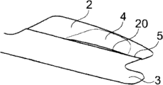
Fig. 3 to Fig. 9 is the block diagram of first kind of special form of implementation of car inside liner 1 of the present invention.Fig. 3 shows a section of the gauge panel on the copilot side, and the first lining member 2 and the second lining member 3 are arranged, these two lining members recline mutually and form one common, appreciiable, along the boundary line 5 of gauge panel longitudinal extension.
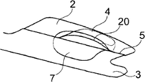
Fig. 4 illustrates when opening air bag 7 the appreciiable first step hardly, and wherein, air bag 7 is easy to extruding gasbag cover plate 4 up.This air bag cover plate 4 is made of the material that an energy plastic expansion that limits stretches, and a specified line of rupture that passes through the material separation formation of nature in 5 zones, boundary line is only arranged.Therefore on boundary line 5, formed a safety air bag clearance hole 20.Fig. 4 had shown the interspace on the boundary line 5 already, and the plastic deformation by air bag cover plate 4 among the Fig. 5 to Fig. 9 below of this gap develops into an enough big air bag clearance hole 20.
Fig. 5 had shown an air bag 7 that comes out from air bag clearance hole 20 already.For this reason, further plasticity is outstanding from remaining lining spare 2 for this air bag cover plate 4.Inflatable air bag 7 automatically obtains an injection channel that is used for to the automotive interior expansion in the zone of natural boundary line 5.
Be deployed into its given upperlimit at air bag described in Fig. 6 to Fig. 97.Wherein, described air bag cover plate 4 is distortion or plasticity stretching, extension fully, therefore, obtains the upperlimit of air bag clearance hole 20.
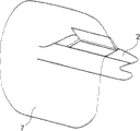
Second kind of special form of implementation of car inside liner 1 of the present invention has been shown in Figure 10 to Figure 17.The same with above-mentioned first kind of form of implementation, car inside liner 1 comprises the first lining member 2 and the second lining member 3.Air bag cover plate 4 is integrated in the first lining member 2, the specified fracture position on being located at end 23 (boundary line 5), also is formed with the perforation 15,16 of described air bag cover plate 4 from the below, so that they are easy to be torn when air bag 7 launches.The end 23 of createing clearance hole overlaps with boundary line 5, and the boundary line stretches out by end 23 in side direction, and the second lining member 2 and the second lining member 3 are separated.
Figure 11 illustrates the first step, and in this step, described air bag cover plate 4 separates with the first lining member 2 in perforation 15,16.
How figure 12 illustrates air bag cover plate 4 upwards opens along hinge axis 24 as airbag cover.Figure 13 to Figure 17 shows air bag 7 by the order of time and how to launch from car inside liner 1, and wherein, described air bag cover plate 4 upwards opens all the time, and farthest leans against on the Windshield shown in Fig. 1 26.
Especially with reference to diagram of the present invention, wherein, these accompanying drawings only schematically illustrate, and proportionally do not illustrate.
List of numerals
1 car inside liner
2 first lining members
3 second lining members
4 air bag cover plates
5 boundary lines
6 gauge panels
7 air bags
8 air bag modules
9 gas generators
10 automobile main cabins
12 hinge guipures
14 supports
15 perforation
16 perforation
17,18,19 clamping plate
20 air bag clearance holes
23 ends
24 hinge axis
26 Windshield
Claims (15)
1. one kind is used for one or morely being contained in automobile main cabin (10) or with the automobile component of described automobile main cabin adjacency, be particularly useful for the car inside liner (1) of automobile instrument panel (6), it has an air bag cover plate (6), below an air bag (7) is contained in the air bag module (8) that play supporting role at described air bag cover plate, it is characterized in that, described car inside liner (1) has at least two lining members (2 that separate, 3), described two lining member designs are used to cover each zone of one or more automobile components that install, be particularly useful for covering the gauge panel (6) of copilot side, wherein, the first lining member (2) comprises described air bag cover plate (4) at least in part, the second lining member (3) forms the boundary line that can see (5) with described air bag cover plate (4), wherein, in the process that described air bag (7) launches, in described car inside liner (1), in described boundary line (5) zone, form an air bag clearance hole (20) at least in part.
2. by the described car inside liner of claim 1 (1), it is characterized in that the described first and second lining members (2,3) are made by different materials, wherein, the described first and/or second lining member (2,3) has structure foaming and/or multilayer respectively.
3. by claim 1 or 2 described car inside liners (1), it is characterized in that described at least air bag cover plate (4) can produce plastic deformation and/or can stretch along an assigned direction at least in its plane under the gas filed effect of described air bag (7).
4. by one of claim 1 to 3 described car inside liner (1), it is characterized in that, described air bag cover plate (4) is designed to one centers on the valve that hinge axis (24) can be swung.
5. by one of claim 1 to 4 described car inside liner (1), it is characterized in that described boundary line (5) have the resistance that significantly reduces or be approximately zero as specified line of rupture when forming described air bag clearance hole (20).
6. by one of claim 1 to 5 described car inside liner (1), it is characterized in that described air bag cover plate (4) is connected with described first lining member (2) hinge, especially swing or be rotationally connected.
7. by one of claim 1 to 6 described car inside liner (1), it is characterized in that described hinge connection is designed to netted or has a netted reinforcing member.
8. by one of claim 1 to 7 described car inside liner (1), it is characterized in that, described air bag cover plate (4) has the specified fracture position or the perforation (15 of some other contiguous design at its periphery, 16), the specified fracture position of described some other contiguous design or perforation especially are arranged in the downside of described air bag cover plate (4).
9. by one of claim 1 to 8 described car inside liner (1), it is characterized in that described air bag cover plate (4) is connected with the described second lining member (3) by openable clip means (17 to 19) in described boundary line (5) zone at least.
10. by one of claim 1 to 8 described car inside liner (1), it is characterized in that the connection mode by groove-key links to each other the described first and second lining members (2,3) in described boundary line (5) zone at least.
11. by one of claim 1 to 10 described car inside liner (1), it is characterized in that the described second lining member (3) is designed to can be offset against the opening direction of described cover plate (4) or sink at least in described boundary line (5) zone in the process that described air bag (7) launches.
12. by one of claim 1 to 11 described car inside liner (1), it is characterized in that, laterally see along automobile, the support (14) of described air bag module (8) is designed to V-type or U type, a leg of described support links to each other directly or indirectly with described lining member (2), another leg of described support links to each other directly or indirectly with described lining member (3), thus, described air bag cover plate (4) is between described two legs or being connected and fixed between the position of they and described two lining member (2,3).
13., it is characterized in that described car inside liner (1) is bearing on the described air bag module (8) that is fixed on the crossbeam by one of claim 1 to 12 described car inside liner (1).
14. by one of claim 1 to 8 described car inside liner (1), it is characterized in that, described air bag cover plate (4) is designed to be made up of two parts, the each several part of described air bag cover plate (4) designs respectively at the described first lining member and the second lining member (2,3) on, described boundary line (5) are arranged between two parts of described air bag cover plate (4).
15., it is characterized in that at least one the lining member in the described lining member (2,3) is made by thermoplastic polyolefin (TPO) or thermoplastic elastomer (TEP) or polycarbonate by one of claim 1 to 14 described car inside liner (1).
Applications Claiming Priority (2)
| Application Number | Priority Date | Filing Date | Title |
|---|---|---|---|
| DE102009016217.8 | 2009-04-03 | ||
| DE102009016217.8A DE102009016217B4 (en) | 2009-04-03 | 2009-04-03 | Vehicle interior trim with an airbag cover |
Publications (2)
| Publication Number | Publication Date |
|---|---|
| CN101856997A true CN101856997A (en) | 2010-10-13 |
| CN101856997B CN101856997B (en) | 2014-08-13 |
Family
ID=42227986
Family Applications (1)
| Application Number | Title | Priority Date | Filing Date |
|---|---|---|---|
| CN201010155529.2A Expired - Fee Related CN101856997B (en) | 2009-04-03 | 2010-04-02 | Airbag cover which forms visible boundary line with interior cladding |
Country Status (4)
| Country | Link |
|---|---|
| US (1) | US8002306B2 (en) |
| CN (1) | CN101856997B (en) |
| DE (1) | DE102009016217B4 (en) |
| GB (1) | GB2469178B (en) |
Families Citing this family (1)
| Publication number | Priority date | Publication date | Assignee | Title |
|---|---|---|---|---|
| DE102018218212B4 (en) * | 2018-10-24 | 2025-09-25 | Audi Ag | Trim part for a vehicle interior |
Citations (5)
| Publication number | Priority date | Publication date | Assignee | Title |
|---|---|---|---|---|
| US5261692A (en) * | 1991-10-19 | 1993-11-16 | Dr. Ing. h.c.e. Porsche AG | Inflatable restraining device for motor vehicle occupants |
| US6435542B2 (en) * | 2000-05-12 | 2002-08-20 | Sanko Gosei Kabushiki Kaisha | Airbag apparatus for front passenger seat |
| US6460874B1 (en) * | 2000-11-20 | 2002-10-08 | Trw Vehicle Safety Systems Inc. | Air bag module deployment door with snap-in feature |
| US20060012153A1 (en) * | 2000-12-08 | 2006-01-19 | Acts Advanced Car Technology Systems Gmbh & Co. Kg | Airbag system for motor vehicle integrated in an inner trim piece |
| US20060214399A1 (en) * | 2005-03-22 | 2006-09-28 | Inoac Corporation | Molded member with foamed body |
Family Cites Families (26)
| Publication number | Priority date | Publication date | Assignee | Title |
|---|---|---|---|---|
| US3817552A (en) * | 1972-08-25 | 1974-06-18 | Gen Motors Corp | Occupant restraint system |
| US5342088A (en) * | 1993-10-05 | 1994-08-30 | Tip Engineering Group | Deployment door patterns for an air bag safety system |
| US5374079A (en) * | 1993-11-15 | 1994-12-20 | Davidson Textron Inc. | Closure for air bag assembly |
| US5460400A (en) * | 1994-05-20 | 1995-10-24 | Takata, Inc. | Passenger-side air bag module with improved assembly features |
| US6012735A (en) * | 1994-06-13 | 2000-01-11 | Textron Automotive Company | Trim panel having air bag door |
| US5445410A (en) * | 1994-06-13 | 1995-08-29 | Chrysler Corporation | Instrument panel assembly having hidden air bag door disposed laterally between vents |
| US5533748A (en) * | 1994-12-01 | 1996-07-09 | Morton International, Inc. | Invisible instrument panel or dashboard airbag cover door |
| US5603524A (en) * | 1995-12-01 | 1997-02-18 | General Motors Corporation | Releasable fastener for air bag deployment cover |
| US5676393A (en) * | 1996-08-06 | 1997-10-14 | Morton International, Inc. | Protective cover for airbag module |
| JP3321531B2 (en) * | 1996-08-26 | 2002-09-03 | 株式会社イノアックコーポレーション | Instrument panel with airbag door |
| DE19650195C1 (en) * | 1996-12-04 | 1997-11-06 | Daimler Benz Ag | Plastic panel bordering air bag cover in motor vehicle |
| JPH1134781A (en) * | 1997-07-16 | 1999-02-09 | Toyo Tire & Rubber Co Ltd | Instrument panel for airbag device and method of manufacturing the same |
| JP2998745B2 (en) * | 1997-10-09 | 2000-01-11 | トヨタ自動車株式会社 | Instrument panel with integrated airbag door |
| US6050595A (en) * | 1998-02-19 | 2000-04-18 | Textron Automotive Company Inc. | Peel back method and apparatus for deployably concealing an air bag behind an instrument panel |
| DE19935625C2 (en) * | 1999-07-29 | 2003-12-04 | Ruetgers Kunststofftechnik Gmb | Airbag cover |
| WO2001081126A1 (en) * | 2000-04-27 | 2001-11-01 | Volkswagen Ag | Airbag device and operating method for the same |
| DE10061438A1 (en) * | 2000-12-09 | 2002-06-27 | Eissmann Gmbh | Dashboard cover |
| DE10117938A1 (en) | 2001-04-10 | 2002-10-31 | Acts Gmbh & Co Kg | Inner trim section and especially dashboard of vehicle has unit to accommodate folded airbag with flat center section covered by single layer airbag fabric and on inner side is connected to airbag cover |
| DE10147547B4 (en) * | 2001-09-26 | 2007-07-19 | Peguform Gmbh | Component for motor vehicles with an airbag cover |
| DE10203407A1 (en) | 2002-01-28 | 2003-08-07 | Peguform Gmbh & Co Kg | Dashboard with integrated cover of airbag unit, comprising textile layer permanently joined to inner surface |
| DE10231131C5 (en) * | 2002-07-10 | 2020-01-09 | Lisa Dräxlmaier GmbH | Dashboard for a vehicle |
| DE10316272A1 (en) * | 2003-04-08 | 2004-11-25 | Johnson Controls Interiors Gmbh & Co. Kg | Paneling, in particular, dashboard for a motor vehicle with an airbag unit comprises an areal, single-piece protective lining which surrounds the entire periphery of the airbag exit opening |
| US7140636B2 (en) * | 2003-05-07 | 2006-11-28 | Lear Corporation | Airbag support assembly for a vehicle instrument panel |
| DE102004038314A1 (en) * | 2004-08-05 | 2006-03-16 | Eissmann Gmbh | Cover for the cover of an airbag |
| JP4113894B2 (en) * | 2006-01-25 | 2008-07-09 | トヨタ自動車株式会社 | Hood airbag device for vehicle |
| US20080007032A1 (en) * | 2006-07-07 | 2008-01-10 | Lear Corporation | Instrument panel assembly with airbag |
-
2009
- 2009-04-03 DE DE102009016217.8A patent/DE102009016217B4/en not_active Expired - Fee Related
-
2010
- 2010-03-19 GB GB1004595.3A patent/GB2469178B/en not_active Expired - Fee Related
- 2010-04-01 US US12/753,006 patent/US8002306B2/en not_active Expired - Fee Related
- 2010-04-02 CN CN201010155529.2A patent/CN101856997B/en not_active Expired - Fee Related
Patent Citations (5)
| Publication number | Priority date | Publication date | Assignee | Title |
|---|---|---|---|---|
| US5261692A (en) * | 1991-10-19 | 1993-11-16 | Dr. Ing. h.c.e. Porsche AG | Inflatable restraining device for motor vehicle occupants |
| US6435542B2 (en) * | 2000-05-12 | 2002-08-20 | Sanko Gosei Kabushiki Kaisha | Airbag apparatus for front passenger seat |
| US6460874B1 (en) * | 2000-11-20 | 2002-10-08 | Trw Vehicle Safety Systems Inc. | Air bag module deployment door with snap-in feature |
| US20060012153A1 (en) * | 2000-12-08 | 2006-01-19 | Acts Advanced Car Technology Systems Gmbh & Co. Kg | Airbag system for motor vehicle integrated in an inner trim piece |
| US20060214399A1 (en) * | 2005-03-22 | 2006-09-28 | Inoac Corporation | Molded member with foamed body |
Also Published As
| Publication number | Publication date |
|---|---|
| US20100253049A1 (en) | 2010-10-07 |
| DE102009016217B4 (en) | 2017-02-16 |
| US8002306B2 (en) | 2011-08-23 |
| GB2469178B (en) | 2014-03-19 |
| GB2469178A (en) | 2010-10-06 |
| GB201004595D0 (en) | 2010-05-05 |
| DE102009016217A1 (en) | 2010-10-07 |
| CN101856997B (en) | 2014-08-13 |
Similar Documents
| Publication | Publication Date | Title |
|---|---|---|
| KR101014124B1 (en) | Driver's seat airbag cushion structure | |
| JP4912416B2 (en) | Airbag guide with cover | |
| KR100516266B1 (en) | Roofliner for a motor vehicle | |
| US8360469B2 (en) | Airbag system | |
| US6832780B2 (en) | Passenger-seat airbag device | |
| JP5321581B2 (en) | Knee airbag device for vehicle | |
| US8167333B2 (en) | Secured force concentrator in a vehicular bolster for airbag retention and deployment | |
| CN100484806C (en) | Airbag cover and airbag device | |
| EP1892161A1 (en) | Occupant restraint device | |
| EP1738970A2 (en) | Airbag apparatus for vehicle and airbag cover | |
| EP1003652B1 (en) | Integral airbag door configuration | |
| US8172257B2 (en) | Safety device for a motor vehicle | |
| CN101856997B (en) | Airbag cover which forms visible boundary line with interior cladding | |
| EP3546298B1 (en) | A vehicle and a method of arranging a knee-airbag-device | |
| US8100431B2 (en) | Front passenger seat airbag apparatus | |
| KR101144544B1 (en) | Airbag module | |
| CN101374703A (en) | Hood airbag device used in a vehicle | |
| US8641084B2 (en) | Ageing-resistant mounting for inflatable airbag module | |
| KR20090019261A (en) | Mounting structure of the airbag module | |
| JP2010241192A (en) | Side airbag device for vehicle | |
| CN111936354A (en) | Exit channel of airbag for motor vehicle | |
| KR20250035869A (en) | Side airbag | |
| KR100698685B1 (en) | Air Bag Device | |
| KR100563831B1 (en) | Installation structure of airbag module | |
| JP2024073736A (en) | Passenger seat airbag device |
Legal Events
| Date | Code | Title | Description |
|---|---|---|---|
| C06 | Publication | ||
| PB01 | Publication | ||
| C10 | Entry into substantive examination | ||
| SE01 | Entry into force of request for substantive examination | ||
| C14 | Grant of patent or utility model | ||
| GR01 | Patent grant | ||
| CF01 | Termination of patent right due to non-payment of annual fee | ||
| CF01 | Termination of patent right due to non-payment of annual fee |
Granted publication date: 20140813 |