CN101885271A - Inkjet printer cartridge detection device - Google Patents
Inkjet printer cartridge detection device Download PDFInfo
- Publication number
- CN101885271A CN101885271A CN 201010148880 CN201010148880A CN101885271A CN 101885271 A CN101885271 A CN 101885271A CN 201010148880 CN201010148880 CN 201010148880 CN 201010148880 A CN201010148880 A CN 201010148880A CN 101885271 A CN101885271 A CN 101885271A
- Authority
- CN
- China
- Prior art keywords
- ink
- pipeline
- gravity
- socket
- valve
- Prior art date
- Legal status (The legal status is an assumption and is not a legal conclusion. Google has not performed a legal analysis and makes no representation as to the accuracy of the status listed.)
- Granted
Links
Images


Landscapes
- Ink Jet (AREA)
Abstract
本发明是喷墨打印机墨盒检测装置,包括支撑台、第一管路和第二管路。插口设置于支撑台上。第一管路和第二管路沿重力方向的上端部同插口连通。第一管路和第二管路沿重力方向的下端部均位于插口沿重力方向的下方。在重力方向上,第一管路沿重力方向的下端部介于插口和第二管路沿重力方向的下端部之间。第一管路和第二管路中分别设置有第一和第二阀门。自插口至第一管路由第一阀门控制的管段内部充有与墨盒内容墨水同效的液体。自插口至第二管路由第二阀门控制的管段内部充有与墨盒内容墨水同效的液体。该检测装置可准确测试墨盒的供墨性能,其结构简单,成本低廉。
The invention is an ink-jet printer ink box detection device, which includes a support table, a first pipeline and a second pipeline. The socket is arranged on the support platform. The upper ends of the first pipeline and the second pipeline along the direction of gravity communicate with the socket. The lower ends of the first pipeline and the second pipeline along the direction of gravity are located below the socket along the direction of gravity. In the direction of gravity, the lower end of the first pipeline in the direction of gravity is interposed between the socket and the lower end of the second pipeline in the direction of gravity. First and second valves are respectively arranged in the first pipeline and the second pipeline. The interior of the pipe section controlled by the first valve from the socket to the first pipe is filled with liquid having the same effect as the ink contained in the ink cartridge. The inside of the pipe section controlled by the second valve from the socket to the second pipe is filled with liquid having the same effect as the ink contained in the cartridge. The detection device can accurately test the ink supply performance of the ink cartridge, and has the advantages of simple structure and low cost.
Description
技术领域technical field
本发明涉及应用于喷墨打印机墨盒的检测装置,特别是其中以阀门作为墨盒中墨水流动控制机构的喷墨打印机墨盒的检测装置。The invention relates to a detection device for an ink-jet printer ink box, in particular to a detection device for an ink-jet printer ink box in which a valve is used as an ink flow control mechanism in the ink box.
背景技术Background technique
喷墨型打印机,其打印方式通常是由墨盒之类的墨水容器提供墨源,经由相应的墨水流动管道将墨水输运至记录头,在打印信号的驱动下将墨水自记录头上设置的喷嘴喷射至纸张等记录介质上,来完成字符或图形的记录。常见的市售喷墨打印机根据其喷嘴的结构形式,可以分为压电式喷墨打印机和气泡式喷墨打印机。For inkjet printers, the printing method is usually provided by an ink container such as an ink cartridge, and the ink is transported to the recording head through the corresponding ink flow channel, and the ink is sent from the nozzle set on the recording head under the drive of the printing signal. Spray onto recording media such as paper to complete the recording of characters or graphics. Common commercially available inkjet printers can be divided into piezoelectric inkjet printers and bubble inkjet printers according to the structure of their nozzles.
压电式喷墨打印机,是在其记录头喷嘴附近的墨水流动管道两侧各设置一块或多块压电晶体。压电晶体受到由数据调制的打印信号控制,产生收缩或膨胀变形,挤压喷嘴中的墨水自喷嘴射出后形成微细的液滴,溅落至记录介质例如纸张的页面上,形成一个记录点。Piezoelectric inkjet printers are equipped with one or more piezoelectric crystals on both sides of the ink flow channel near the nozzle of the recording head. The piezoelectric crystal is controlled by the printing signal modulated by the data to produce contraction or expansion deformation. The ink in the extrusion nozzle is ejected from the nozzle to form fine droplets, which splash onto the recording medium such as the page of paper to form a recording point.
气泡式喷墨打印机,其记录头结构与压电式喷墨打印机相似。它同压电式喷墨打印机的差别是,气泡式喷墨打印机在记录头喷嘴附近的墨水流动管道内壁或外壁上设置了加热电极。数据调制的电脉冲信号被送到喷嘴的加热电极上,加热电极快速升温,使喷嘴附近的墨水迅速汽化,形成汽泡。汽泡膨胀产生的压力使墨水自喷嘴射出后形成一个个微细的墨滴,溅落至纸张的页面上。电脉冲消失后,墨水蒸汽凝聚或收缩,喷嘴内的墨水填充至蒸汽凝聚或收缩后的空间并使其液面通过表面张力维持在与喷嘴外表面齐口的水平。记录头抽取墨水后形成的负压引导储墨腔内的墨水流入喷嘴所在的墨水流动管道。Bubble inkjet printers have a recording head structure similar to piezoelectric inkjet printers. The difference between it and the piezoelectric inkjet printer is that the bubble inkjet printer has a heating electrode on the inner or outer wall of the ink flow channel near the nozzle of the recording head. The electrical pulse signal modulated by the data is sent to the heating electrode of the nozzle, and the heating electrode heats up rapidly, so that the ink near the nozzle is rapidly vaporized to form bubbles. The pressure generated by the expansion of the bubbles causes the ink to form tiny ink droplets after being ejected from the nozzle, and splash onto the page of the paper. After the electric pulse disappears, the ink vapor condenses or shrinks, and the ink in the nozzle fills the space after the vapor condenses or shrinks, and the liquid level is maintained at the same level as the outer surface of the nozzle through surface tension. The negative pressure formed after the ink is drawn by the recording head guides the ink in the ink storage chamber to flow into the ink flow channel where the nozzle is located.
无论是压电式喷墨打印机,还是气泡式喷墨打印机,与其相匹配的墨水容器或墨盒均需要考虑以下问题,即墨盒的出墨口应当在有打印任务时处于开启状态,以适应喷墨打印机的需求向其喷嘴供应墨水,而在无打印任务时处于关闭状态,以及时地掐断墨水的流动和防止墨水外流。现有喷墨打印机使用的墨盒,较多地在其内部使用了阀门,其中大部分为单向阀,来实现前述墨水的流动状态的控制。Whether it is a piezoelectric inkjet printer or a bubble inkjet printer, the ink container or ink cartridge that matches it needs to consider the following issues, that is, the ink outlet of the ink cartridge should be open when there is a printing task, so as to adapt to the ink jet. The printer needs to supply ink to its nozzles, and it is closed when there is no printing task, so as to cut off the flow of ink in time and prevent the ink from flowing out. The ink cartridges used in existing inkjet printers mostly use valves inside, most of which are check valves, to realize the control of the flow state of the aforementioned ink.
墨盒单向阀之所以能实现上述功能,主要是因为单向阀由密封部件以及弹性部件,例如弹簧组成,或者是直接采用具有弹性特点的材料,例如橡胶制成。弹性部件或弹性材料的使用,均可保证在墨盒与打印头之间的压强差小于某个预定值时,能够依靠材料自身的弹性所产生的弹力,迫使单向阀处于关闭状态;而当墨盒与打印头之间的压强差超过某个预定值时,又能够依靠材料自身的弹性形变,迫使单向阀处于打开状态。The reason why the ink cartridge check valve can realize the above functions is mainly because the check valve is made of sealing parts and elastic parts, such as springs, or is directly made of materials with elastic properties, such as rubber. The use of elastic parts or elastic materials can ensure that when the pressure difference between the ink cartridge and the print head is less than a predetermined value, the elastic force generated by the elasticity of the material itself can be used to force the one-way valve to be in a closed state; and when the ink cartridge When the pressure difference with the print head exceeds a predetermined value, the one-way valve can be forced to open by relying on the elastic deformation of the material itself.
鉴于墨盒单向阀所必须具有的打开/关闭功能,要求作为其组成部分的弹簧或橡胶必须能够完成因压强差的不断变化而提供可靠和稳定的弹力或形变,并且不能因材料的长期老化、或与墨水溶液的化学反应、以及与其他部件的密封性配合等潜在隐患,造成其所提供的弹力或形变发生较大范围的变动,从而导致单向阀无法按预期的设定值进行打开或关闭动作。然而,由于生产设备、材料性能、装配过程等均存在不确定的变化因素,使得单向阀的调控能力往往难于保证良好的稳定性,影响墨盒的连续供墨性能。因此,在墨盒的生产过程中,检测墨盒的连续供墨性能,也就是检测单向阀的启闭功能,就成为控制其质量水平的必要手段。通常的检测方式是把墨盒放在打印机上进行打印检测,以验证其在打印过程中的连续供墨性能。这种方法能比较真实地反映墨盒的正常工作状态,但是缺点也是显而易见的:其一,每种墨盒都需要与之相适应的喷墨打印机,所需检测资源较多;其二,检测过程中需消耗大量纸张,浪费严重;其三,检测效率较低,用于检测的喷墨打印机占用较多的成本,对于有效利用有限的物质资源极为不利。In view of the opening/closing function that the check valve of the ink cartridge must have, it is required that the spring or rubber as its component must be able to provide reliable and stable elastic force or deformation due to the continuous change of the pressure difference, and it cannot be damaged due to long-term aging of the material, Potential hidden dangers such as chemical reactions with ink solutions, and sealing cooperation with other components, resulting in a wide range of changes in the elastic force or deformation provided by it, resulting in the one-way valve not being able to open or close according to the expected set value. Close action. However, due to uncertain factors such as production equipment, material performance, and assembly process, it is often difficult to ensure good stability in the control ability of the check valve, which affects the continuous ink supply performance of the ink cartridge. Therefore, in the production process of the ink cartridge, detecting the continuous ink supply performance of the ink cartridge, that is, detecting the opening and closing function of the one-way valve, has become a necessary means to control its quality level. The usual detection method is to put the ink cartridge on the printer for printing detection to verify its continuous ink supply performance during the printing process. This method can truly reflect the normal working status of the ink cartridges, but the disadvantages are also obvious: first, each ink cartridge requires an inkjet printer that is compatible with it, and requires more testing resources; A large amount of paper needs to be consumed, and the waste is serious; third, the detection efficiency is low, and the inkjet printer used for detection takes up a lot of cost, which is extremely unfavorable for the effective use of limited material resources.
发明内容Contents of the invention
针对上述问题,本发明目的是提供一种用于检测喷墨打印机墨盒供墨性能的检测装置。该检测装置可用于大部分使用单向阀作为其墨水流动调节机构的墨盒,而无需针对每种墨盒使用不同的打印机作为该墨盒的检测设备,且在检测过程中免却了因使用纸张等消耗性材料形成的浪费。In view of the above problems, the object of the present invention is to provide a detection device for detecting the ink supply performance of the ink cartridge of an inkjet printer. The detection device can be used for most ink cartridges that use a one-way valve as its ink flow adjustment mechanism, without using a different printer for each ink cartridge as the detection equipment for the ink cartridge, and avoids the consumption of paper and other wastes during the detection process. waste of permanent materials.
按照上述本发明目的设计的喷墨打印机墨盒检测装置,包括用于承载墨盒的支撑台、第一管路和第二管路。支撑台上设置有用于同墨盒的出墨口对接的插口。第一管路和第二管路沿重力方向的上端部分别同插口连通。第一管路和第二管路沿重力方向的下端部同时位于插口沿重力方向的下方。在重力方向上,第一管路沿重力方向的下端部的位置介于插口的位置和第二管路沿重力方向的下端部的位置之间。第一管路和第二管路中分别设置有用于控制该管路通断的第一阀门和第二阀门。自插口至第一管路由第一阀门控制的管段内部充满了与墨盒内容墨水使用功效相同的液体。自插口至第二管路由第二阀门控制的管段内部充满了与墨盒内容墨水使用功效相同的液体。The inkjet printer ink cartridge detection device designed according to the purpose of the present invention includes a support table for carrying the ink cartridge, a first pipeline and a second pipeline. A socket for docking with the ink outlet of the ink cartridge is arranged on the supporting platform. The upper ends of the first pipeline and the second pipeline along the direction of gravity communicate with the socket respectively. The lower ends of the first pipeline and the second pipeline along the direction of gravity are simultaneously located below the socket along the direction of gravity. In the direction of gravity, the position of the lower end of the first pipeline in the direction of gravity is between the position of the socket and the position of the lower end of the second pipeline in the direction of gravity. The first pipeline and the second pipeline are respectively provided with a first valve and a second valve for controlling the on-off of the pipeline. The interior of the pipe section controlled by the first valve from the socket to the first pipe is filled with liquid with the same use effect as the ink contained in the ink cartridge. The inside of the pipe section controlled by the second valve from the socket to the second pipe is filled with the liquid with the same use effect as the ink contained in the ink cartridge.
优选地,前述喷墨打印机墨盒检测装置,其插口沿重力方向的下端部与三通管的第一端口连通,第一管路和第二管路沿重力方向的上端部分别与三通管的第二端口和第三端口连通。Preferably, the lower end of the socket of the aforementioned inkjet printer cartridge detection device in the direction of gravity communicates with the first port of the three-way pipe, and the upper ends of the first pipeline and the second pipeline in the direction of gravity are respectively connected to the three-way pipe. The second port communicates with the third port.
择优地,前述喷墨打印机墨盒检测装置,其第一阀门位于第一管路沿重力方向的下端部附近,第二阀门位于第二管路沿重力方向的下端部附近。Preferably, the first valve is located near the lower end of the first pipeline in the direction of gravity, and the second valve is located near the lower end of the second pipeline in the direction of gravity.
较好地,前述喷墨打印机墨盒检测装置,在重力方向上,其第一管路和第二管路沿重力方向的下端部的下方设置有用于盛装液体的容器。Preferably, in the aforementioned inkjet printer cartridge detection device, in the direction of gravity, a container for containing liquid is provided below the lower ends of the first pipeline and the second pipeline along the direction of gravity.
更好地,前述喷墨打印机墨盒检测装置,自其插口至第二管路沿重力方向的下端部之间在重力方向上对应的压力不小于喷墨打印机对出墨口施加的抽吸压力,自插口至第一管路沿重力方向的下端部之间在重力方向上对应的压力小于喷墨打印机对出墨口施加的抽吸压力。Preferably, the aforementioned inkjet printer ink cartridge detection device, the corresponding pressure in the direction of gravity from its socket to the lower end of the second pipeline along the direction of gravity is not less than the suction pressure applied by the inkjet printer to the ink outlet, The corresponding pressure in the direction of gravity between the socket and the lower end of the first pipeline along the direction of gravity is smaller than the suction pressure exerted by the inkjet printer on the ink outlet.
本发明的喷墨打印机墨盒检测装置,是利用液位落差来测试单向阀的启闭功能,亦即墨盒的连续供墨性能。由于在该检测装置中使用了与墨盒内容墨水使用功效相同的液体,因而其模拟的检测环境几达至墨盒的实际工作环境,从而保证所检测的单向阀启闭功能更符合其在喷墨打印机上的实际工作需要,使得所检测的单向阀启闭功能与其在喷墨打印机上的实际工作环境之间具有更高的吻合度,从而获得较为准确、可靠的检测结果。另一方面,该检测装置仅需要几个简单的常用构件即可构成,其设备的生产和原料成本均极为低廉,但却具有极高的实用价值。The detection device of the ink cartridge of the inkjet printer of the present invention uses the liquid level drop to test the opening and closing function of the one-way valve, that is, the continuous ink supply performance of the ink cartridge. Since the detection device uses a liquid with the same effect as the ink contained in the ink cartridge, the simulated detection environment is almost the same as the actual working environment of the ink cartridge, thus ensuring that the detected opening and closing function of the one-way valve is more in line with its performance in inkjet. The actual work requirements on the printer make the detection of the opening and closing function of the one-way valve more consistent with the actual working environment on the inkjet printer, thereby obtaining more accurate and reliable detection results. On the other hand, the detection device only needs a few simple common components, and the production and raw material costs of the equipment are extremely low, but it has extremely high practical value.
附图说明Description of drawings
图1现有喷墨打印机墨盒剖视图。Fig. 1 is a sectional view of an existing inkjet printer ink cartridge.
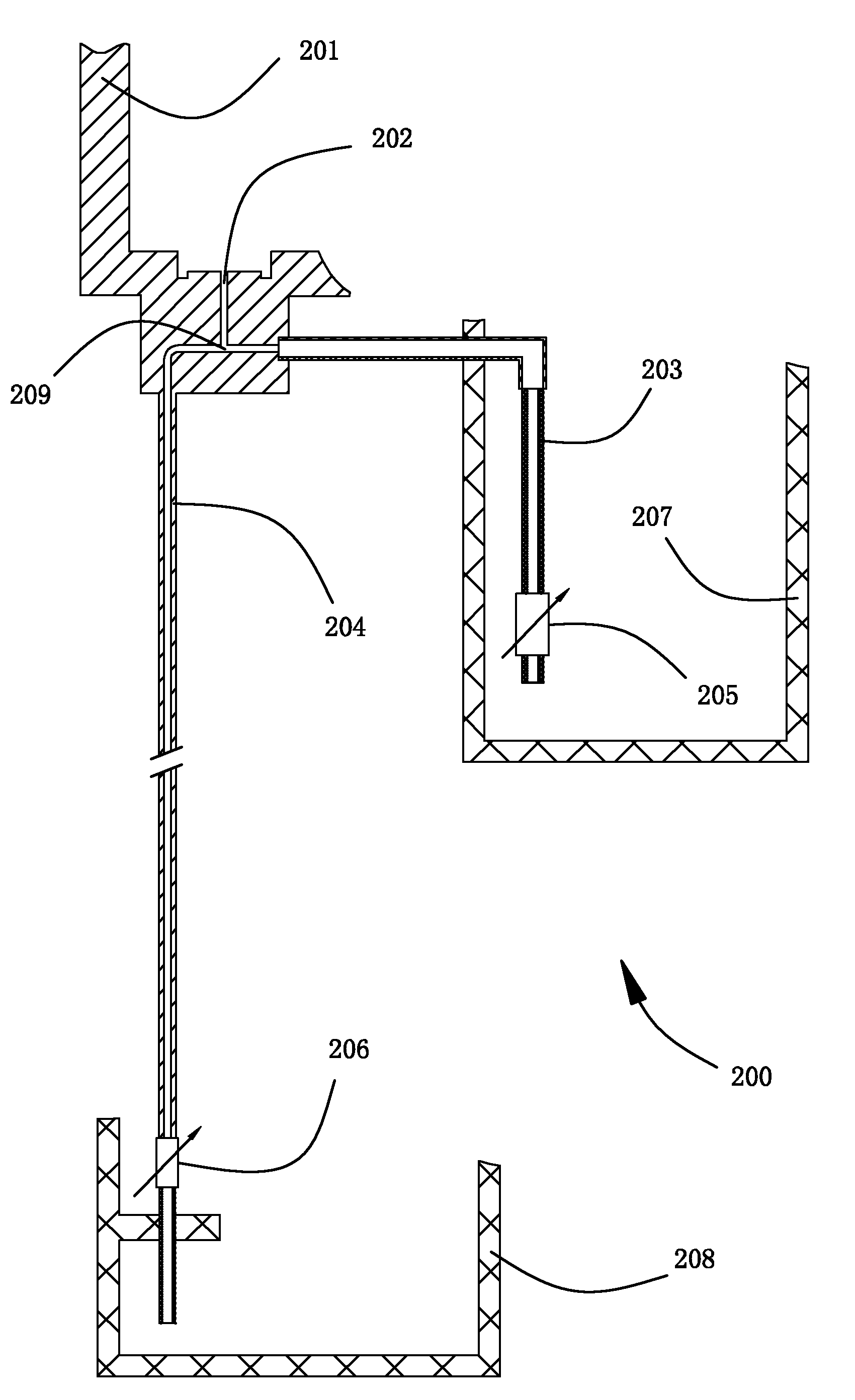
图2本发明喷墨打印机墨盒检测装置平面结构示意图。Fig. 2 is a schematic diagram of the planar structure of the inkjet printer ink cartridge detection device of the present invention.
图3本发明喷墨打印机墨盒检测装置工作状态平面结构示意图。Fig. 3 is a schematic plan view of the working state of the inkjet printer ink cartridge detection device of the present invention.
图4本发明喷墨打印机墨盒检测装置工作过程平面结构示意图一。Fig. 4 is a planar structural schematic diagram of the working process of the inkjet printer ink cartridge detection device of the present invention.
图5本发明喷墨打印机墨盒检测装置工作过程平面结构示意图二。Figure 5 is the second schematic diagram of the planar structure of the working process of the inkjet printer ink cartridge detection device of the present invention.
图6本发明喷墨打印机墨盒检测装置工作过程平面结构示意图三。Fig. 6 is the third schematic plan view of the working process of the inkjet printer ink cartridge detection device of the present invention.
图7本发明喷墨打印机墨盒检测装置工作过程平面结构示意图四。Fig. 7 is a schematic diagram of the planar structure of the working process of the inkjet printer ink cartridge detection device of the present invention (fourth).
具体实施方式Detailed ways
下面结合附图详细描述本发明喷墨打印机墨盒检测装置。The inkjet printer ink cartridge detection device of the present invention will be described in detail below in conjunction with the accompanying drawings.
在介绍本发明检测装置之前,先行描述喷墨打印机墨盒的基本构造。参见图1,示出了现有喷墨打印机墨盒100的剖视图。墨盒100上设置有用于容纳墨水的储墨腔106和用于向喷墨打印机供应墨水的出墨口102。在储墨腔106中贮存有墨水103。储墨腔106和出墨口102之间通过第一墨水通道107和第二墨水通道104保持连通,储墨腔106和出墨口102之间的其他部分保持隔绝状态。第一墨水通道107和第二墨水通道104上各设置有一个单向阀。设置于第一墨水通道107上的单向阀105,其开启方向从出墨口102指向储墨腔106,亦即在单向阀105开启的状态下,墨水将自出墨口102内灌入储墨腔106中,在单向阀105关闭的状态下,出墨口102内的墨水和储墨腔106中的墨水103相对于第一墨水通道107而言将保持相互隔断互不流通的状态。设置于第二墨水通道104上的单向阀101,其开启方向从储墨腔106指向出墨口102,亦即在单向阀101开启的状态下,墨水将自储墨腔106中流入出墨口102内,在单向阀101关闭的状态下,出墨口102内的墨水和储墨腔106中的墨水103相对于第二墨水通道104而言将保持相互隔断互不流通的状态。在这种构造方式下,单向阀105承担的角色是在出墨口102内墨水的压力高于储墨腔106中墨水103的压力时将出墨口102内的压力释放到储墨腔106中,亦即单向阀105承担的任务是释放压力,因此它承担的是泄压阀的角色;单向阀101承担的角色是在储墨腔106中墨水103的压力高于出墨口102内墨水的压力时将储墨腔106中的墨水103压入出墨口102内,以便向喷墨打印机供应墨水,亦即单向阀101承担的任务是供应墨水,因此它承担的是供墨阀的角色。Before introducing the detection device of the present invention, the basic structure of the ink-jet printer cartridge will be described first. Referring to FIG. 1 , a cross-sectional view of a conventional
以下介绍用于检测前述喷墨打印机墨盒100供墨性能的本发明检测装置200的构成状况和工作方式。The composition and working method of the
参见图2、3,示出了本发明喷墨打印机墨盒检测装置200的平面结构示意图和其处于工作状态时的平面结构示意图,同时结合图1。Referring to FIGS. 2 and 3 , there are shown a schematic plan view of the inkjet printer ink
该检测装置200的主要构件包括支撑台201、第一管路203和第二管路204。在支撑台201上设置有插口202。在检测墨盒100的供墨性能,也就是检测单向阀101的开关特性时,插口202用于同墨盒100的出墨口102对接,以便储墨腔106中的墨水能够被引流到插口202的管腔中。插口202沿重力方向的下端部与三通管209的第一端口连通。第一管路203和第二管路204沿重力方向的上端部分别与三通管209的第二端口和第三端口连通。第一管路203和第二管路204沿重力方向的下端部,它们的位置同时位于插口202沿重力方向的下方。在重力方向上,第一管路203沿重力方向的下端部,其位置介于插口202所处位置和第二管路204沿重力方向的下端部所处位置之间。在第一管路203和第二管路204中,分别设置有第一阀门205和第二阀门206。第一阀门205和第二阀门206分别用于控制第一管路203和第二管路204的通断。第一阀门205的位置靠近第一管路203沿重力方向的下端部。第二阀门206的位置靠近第二管路204沿重力方向的下端部。在自插口202至第一管路203的由第一阀门205控制的管段内部,充满了液体,该液体与墨盒100内容纳的墨水103具有相同的使用功效。在自插口202至第二管路204的由第二阀门206控制的管段内部,亦充满了液体,该液体与墨盒100内容纳的墨水103具有相同的使用功效。在应用检测装置200时,前述充入插口202、第一管路203和第二管路204中的液体一般使用与墨盒100内所容纳墨水103同质的液体。在重力方向上,自插口202至第一管路203沿重力方向的下端部之间,该段管路中所充填液体对应的压力小于喷墨打印机在实际工作状态下对出墨口102施加的抽吸压力。在重力方向上,自插口202至第二管路204沿重力方向的下端部之间,该段管路中所充填液体对应的压力不小于喷墨打印机在实际工作状态下对出墨口102施加的抽吸压力。在重力方向上,于第一管路203和第二管路204的沿重力方向的下端部的下方,分别设置有用于盛装液体的容器207、208。The main components of the
在检测单向阀101的开关特性时,如图3,把墨盒100放置于支撑台201上,并把墨盒100的出墨口102对接到设置在支撑台201上的插口202中。在此检测准备阶段,第一阀门205和第二阀门206保持关闭状态,并且,在自插口202至第一管路203由第一阀门205控制的管段内部,充满了与墨盒100内容纳的墨水103同质的液体。在自插口202至第二管路204由第二阀门206控制的管段内部,充满了与墨盒100内容纳的墨水103同质的液体。When detecting the switching characteristics of the one-
检测时,见图4,结合图1,首先,保持第一阀门205处于关闭状态,在此状态下开启第二阀门206,在容纳于插口202和第二管路204沿重力方向下端部之间的液体压力作用下,墨盒100中的单向阀101被迫开启,储墨腔106中的墨水103流入出墨口102,随即依次经插口202、第二管路204沿重力方向的下端部流入液体盛放容器208中。在该检测结果下,由于自插口202至第二管路204沿重力方向下端部之间所充填液体对应的压力不小于喷墨打印机在实际工作状态下对出墨口102施加的抽吸压力,表明在不小于喷墨打印机实际抽吸压力的状态下,单向阀101能够被顺利打开。During detection, see Fig. 4, in conjunction with Fig. 1, first, keep the
在图4对应的检测结果和状态的基础上,见图5,结合图1,关闭第二阀门206,之后开启第一阀门205,在容纳于插口202和第一管路203沿重力方向下端部之间的液体压力作用下,墨盒100中的单向阀101不能被开启,墨水103不会从墨盒100中流出。在该检测结果下,由于自插口202至第一管路203沿重力方向下端部之间所充填液体对应的压力小于喷墨打印机在实际工作状态下对出墨口102施加的抽吸压力,表明在小于喷墨打印机实际抽吸压力的状态下,单向阀101仍然处于关闭状态。On the basis of the detection results and states corresponding to FIG. 4, see FIG. 5, in conjunction with FIG. 1, close the
经过图4、5对应的两步检测后,单向阀101如果满足图4、5对应的两步检测所得的结果,表明单向阀101只能在不小于喷墨打印机实际抽吸压力的状态下被打开,而在小于喷墨打印机实际抽吸压力的状态下则处于关闭状态,该单向阀101功能符合要求,墨盒100合格。After the two-step detection corresponding to Figures 4 and 5, if the
对于墨盒100检测性能不合格的判定,参见图6,结合图1,首先,保持第一阀门205处于关闭状态,在此状态下开启第二阀门206,在容纳于插口202和第二管路204沿重力方向下端部之间的液体压力作用下,墨盒100中的单向阀101仍然处于关闭状态,储墨腔106中的墨水103以及出墨口102、插口202、第二管路204中的墨水不能流入液体盛放容器208中。在该检测结果下,由于自插口202至第二管路204沿重力方向下端部之间所充填液体对应的压力不小于喷墨打印机在实际工作状态下对出墨口102施加的抽吸压力,表明在不小于喷墨打印机实际抽吸压力的状态下,单向阀101仍然处于关闭状态,不能实现墨盒100对喷墨打印机的墨水供应,该墨盒100不合格。For the determination of the unqualified detection performance of the
对于墨盒100检测性能不合格的另一种判定情形,参见图7,结合图1,关闭第二阀门206,之后开启第一阀门205,在容纳于插口202和第一管路203沿重力方向下端部之间的液体压力作用下,墨盒100中的单向阀101被迫开启,储墨腔106中的墨水103流入出墨口102,随即依次经插口202、第一管路203沿重力方向的下端部流入液体盛放容器207中。在该检测结果下,由于自插口202至第一管路203沿重力方向下端部之间所充填液体对应的压力小于喷墨打印机在实际工作状态下对出墨口102施加的抽吸压力,表明在小于喷墨打印机实际抽吸压力的状态下,单向阀101仍然能够被打开。在此基础上,如果第一阀门205和第二阀门206逐个被打开时,墨盒100中的墨水103将非分别流入液体盛放容器207、208中。如此,实际应用中在小于喷墨打印机实际抽吸压力的状态下,墨盒100中的墨水103可能流出到墨盒100外部,单向阀101的关闭功能不能满足防止墨水103外流的要求,该墨盒100不合格。For another determination of the unqualified detection performance of the
Claims (5)
Priority Applications (1)
| Application Number | Priority Date | Filing Date | Title |
|---|---|---|---|
| CN2010101488809A CN101885271B (en) | 2010-04-17 | 2010-04-17 | Detecting device of ink box of ink jet printer |
Applications Claiming Priority (1)
| Application Number | Priority Date | Filing Date | Title |
|---|---|---|---|
| CN2010101488809A CN101885271B (en) | 2010-04-17 | 2010-04-17 | Detecting device of ink box of ink jet printer |
Publications (2)
| Publication Number | Publication Date |
|---|---|
| CN101885271A true CN101885271A (en) | 2010-11-17 |
| CN101885271B CN101885271B (en) | 2011-09-14 |
Family
ID=43071425
Family Applications (1)
| Application Number | Title | Priority Date | Filing Date |
|---|---|---|---|
| CN2010101488809A Expired - Fee Related CN101885271B (en) | 2010-04-17 | 2010-04-17 | Detecting device of ink box of ink jet printer |
Country Status (1)
| Country | Link |
|---|---|
| CN (1) | CN101885271B (en) |
Cited By (1)
| Publication number | Priority date | Publication date | Assignee | Title |
|---|---|---|---|---|
| CN102229286A (en) * | 2011-04-25 | 2011-11-02 | 珠海天威技术开发有限公司 | System and method for testing ink supplying container |
Citations (3)
| Publication number | Priority date | Publication date | Assignee | Title |
|---|---|---|---|---|
| JPH09193414A (en) * | 1996-01-16 | 1997-07-29 | Canon Inc | Liquid holding / supplying device and holding / supplying method thereof |
| CN2472927Y (en) * | 2001-04-16 | 2002-01-23 | 珠海飞马耗材有限公司 | Ink feeding and testing device for ink box |
| JP2005138580A (en) * | 2003-10-17 | 2005-06-02 | Seiko Epson Corp | Liquid pressure control device, liquid ejection device provided with the liquid pressure control device, and liquid pressure control program |
-
2010
- 2010-04-17 CN CN2010101488809A patent/CN101885271B/en not_active Expired - Fee Related
Patent Citations (3)
| Publication number | Priority date | Publication date | Assignee | Title |
|---|---|---|---|---|
| JPH09193414A (en) * | 1996-01-16 | 1997-07-29 | Canon Inc | Liquid holding / supplying device and holding / supplying method thereof |
| CN2472927Y (en) * | 2001-04-16 | 2002-01-23 | 珠海飞马耗材有限公司 | Ink feeding and testing device for ink box |
| JP2005138580A (en) * | 2003-10-17 | 2005-06-02 | Seiko Epson Corp | Liquid pressure control device, liquid ejection device provided with the liquid pressure control device, and liquid pressure control program |
Cited By (2)
| Publication number | Priority date | Publication date | Assignee | Title |
|---|---|---|---|---|
| CN102229286A (en) * | 2011-04-25 | 2011-11-02 | 珠海天威技术开发有限公司 | System and method for testing ink supplying container |
| CN102229286B (en) * | 2011-04-25 | 2013-08-21 | 珠海天威技术开发有限公司 | System and method for testing ink supplying container |
Also Published As
| Publication number | Publication date |
|---|---|
| CN101885271B (en) | 2011-09-14 |
Similar Documents
| Publication | Publication Date | Title |
|---|---|---|
| EP2857205B1 (en) | Liquid ejection device and liquid leakage suppression method | |
| US9327504B2 (en) | Liquid ejecting apparatus and liquid supply apparatus | |
| US9327514B2 (en) | Inkjet printing apparatus | |
| US9358801B2 (en) | Liquid supply device | |
| CN106853689A (en) | The positive/negative-pressure ink feeding system and its method of work of a kind of 3D printing equipment | |
| CN101117055A (en) | Apparatus and method for ink supply | |
| CN201703034U (en) | Ink cartridge of ink-jet printer | |
| CN102101386A (en) | Circulating ink supply device | |
| JPWO2009072656A1 (en) | Liquid storage container | |
| JP2009248513A (en) | Printing apparatus | |
| JP4125250B2 (en) | Liquid storage container and recording apparatus using the container | |
| CN201721130U (en) | Inkjet printer ink cartridge | |
| CN201677573U (en) | Ink box of ink-jet printer | |
| CN101332717A (en) | Ink box capable of automatically stopping ink supply | |
| CN201257801Y (en) | Ink cartridge for ink jet printer | |
| CN201659748U (en) | Ink box for ink-jet printer | |
| CN201128275Y (en) | Printer cartridge | |
| JP2019098545A (en) | Inkjet recording device | |
| CN201176028Y (en) | inkjet printer cartridge | |
| CN101885271B (en) | Detecting device of ink box of ink jet printer | |
| CN103895358A (en) | Printer ink box | |
| CN102139576A (en) | Method for filling ink into ink box of ink jet printer | |
| CN201816272U (en) | Ink cartridge of inkjet printer | |
| KR100732379B1 (en) | Ink level control device of large format printer | |
| CN102582270A (en) | Pressure dynamic compensation device and continuous ink supply system using pressure dynamic compensation |
Legal Events
| Date | Code | Title | Description |
|---|---|---|---|
| C06 | Publication | ||
| PB01 | Publication | ||
| C10 | Entry into substantive examination | ||
| SE01 | Entry into force of request for substantive examination | ||
| C14 | Grant of patent or utility model | ||
| GR01 | Patent grant | ||
| CF01 | Termination of patent right due to non-payment of annual fee |
Granted publication date: 20110914 |
|
| CF01 | Termination of patent right due to non-payment of annual fee |