CN101888024B - Cable connector assembly, manufacturing method thereof, conduction terminal and strip thereof - Google Patents
Cable connector assembly, manufacturing method thereof, conduction terminal and strip thereof Download PDFInfo
- Publication number
- CN101888024B CN101888024B CN2009103022980A CN200910302298A CN101888024B CN 101888024 B CN101888024 B CN 101888024B CN 2009103022980 A CN2009103022980 A CN 2009103022980A CN 200910302298 A CN200910302298 A CN 200910302298A CN 101888024 B CN101888024 B CN 101888024B
- Authority
- CN
- China
- Prior art keywords
- terminal
- strip
- crimping
- conductor
- conductive
- Prior art date
- Legal status (The legal status is an assumption and is not a legal conclusion. Google has not performed a legal analysis and makes no representation as to the accuracy of the status listed.)
- Expired - Fee Related
Links
Images


Landscapes
- Coupling Device And Connection With Printed Circuit (AREA)
- Multi-Conductor Connections (AREA)
- Manufacturing Of Electrical Connectors (AREA)
Abstract
一种线缆连接器组件,包括导电端子及与所述导电端子相连接的线缆,所述线缆包括导体及包覆导体的绝缘外层,所述导电端子包括主体部、自主体部向后延伸形成的与所述线缆的导体相压接的导体夹持部及自所述导体夹持部向后延伸的绝缘夹持部,所述导电端子的绝缘夹持部是通过切断端子料带的导引带而形成。
A cable connector assembly, including a conductive terminal and a cable connected to the conductive terminal, the cable includes a conductor and an insulating outer layer covering the conductor, the conductive terminal includes a main body, from the main body to the The conductor clamping part which is formed by extension and crimped with the conductor of the cable and the insulating clamping part extending backward from the conductor clamping part, the insulating clamping part of the conductive terminal is formed by cutting the terminal material The belt guide belt is formed.
Description
【技术领域】 【Technical field】
本发明涉及一种线缆连接器组件,尤其涉及所述线缆连接器组件中的导电端子的端子料带及所述端子料带的制造方法。The invention relates to a cable connector assembly, in particular to a terminal material strip of a conductive terminal in the cable connector assembly and a manufacturing method of the terminal material strip.
【背景技术】 【Background technique】
为适应现代电子工业生产的机械化、高速化,目前用于电连接器内的导电端子一般采用在一长条的料带上冲压制成。通常将长条的金属料带经过冲压形成导电端子,并在冲压成型时制出可将多根端子在适当位置加以连接的引导带。In order to adapt to the mechanization and high-speed production of modern electronics industry, the conductive terminals used in electrical connectors are generally stamped on a long strip of material. Usually, the long strip of metal material is stamped to form conductive terminals, and a guide strip that can connect multiple terminals at appropriate positions is produced during stamping.
在上述制造方法中,端子料带大致一半用来成型导电端子,另一半用作连接导电端子以协助导电端子的运输并实现制造及组装机械化的引导带,而用作连接导电端子的引导带在要求得到单个导电端子时即被切割成废料,因此上述制造方法大大增加了导电端子的制造成本,浪费制作导电端子的原材料。In the above-mentioned manufacturing method, roughly half of the terminal strip is used to form the conductive terminal, and the other half is used as a guide belt for connecting the conductive terminal to assist in the transportation of the conductive terminal and realize the mechanization of manufacturing and assembly. When it is required to obtain a single conductive terminal, it is cut into waste. Therefore, the above manufacturing method greatly increases the manufacturing cost of the conductive terminal and wastes raw materials for making the conductive terminal.
鉴于此,实有必要提供一种改进的端子料带及其制造方法,以克服上述端子料带及其制造方法的缺陷。In view of this, it is necessary to provide an improved terminal material strip and its manufacturing method to overcome the above-mentioned defects of the terminal material strip and its manufacturing method.
【发明内容】 【Content of invention】
本发明的目的在于提供一种降低导电端子制造成本的线缆连接器组件。The purpose of the present invention is to provide a cable connector assembly which reduces the manufacturing cost of the conductive terminal.
为了实现上述目的,本发明提供一种线缆连接器组件,包括导电端子及与所述导电端子相连接的线缆,所述线缆包括导体及包覆导体的绝缘外层,所述导电端子包括主体部、自主体部向后延伸形成的与所述线缆的导体相压接的导体夹持部及自所述导体夹持部向后延伸的绝缘夹持部,所述导电端子的绝缘夹持部是通过切断端子料带的导引带而形成。In order to achieve the above object, the present invention provides a cable connector assembly, including a conductive terminal and a cable connected to the conductive terminal, the cable includes a conductor and an insulating outer layer covering the conductor, the conductive terminal It includes a main body, a conductor clamping portion extended backward from the main body and crimped with the conductor of the cable, and an insulating clamping portion extending backward from the conductor clamping portion, the insulation of the conductive terminal The clamping portion is formed by cutting the guide tape of the terminal strip.
本发明还提供另外一种导电端子,其包括对接部、第一压接部和第二压接部,每一压接部具有一对压接时卷曲的臂部,所述第二压接部的一对臂部展开时形成一纵长条状结构,所述纵长条状结构是由端子料带的导引带直接切断而形成。The present invention also provides another conductive terminal, which includes a butt joint part, a first crimping part and a second crimping part, each crimping part has a pair of arms that are crimped when crimping, and the second crimping part When the pair of arm portions are unfolded, a longitudinal strip structure is formed by directly cutting the guide strip of the terminal strip.
本发明还提供另外一种线缆连接器组件的制造方法,其特征在于:所述制造方法包括如下步骤:The present invention also provides another manufacturing method of a cable connector assembly, characterized in that: the manufacturing method includes the following steps:
提供端子料带,为多排多列结构,所述端子料带中的每个端子包括主体部、第一压接部及第二压接部,每列料带间通过相邻两个端子的第二压接部相互连接,所述连接处形成有第一压痕,每排料带间通过前后两个端子的主体部和第二压接部首尾相连,所述连接处形成有第二压痕;Provide terminal strips, which are multi-row and multi-column structures, each terminal in the terminal strips includes a main body, a first crimping portion, and a second crimping portion, and each row of strips is passed between two adjacent terminals The second crimping parts are connected to each other, and the first indentation is formed at the connection. The main parts of the two front and rear terminals and the second crimping part are connected end-to-end between each discharge belt, and the second crimping part is formed at the connection. mark;
切断端子料带,通过切断第一压痕和第二压痕以得到单个导电端子;cutting the terminal strip, by cutting off the first indentation and the second indentation to obtain a single conductive terminal;
连接导电端子和线缆,所述线缆包括导体及包覆导体的绝缘外层,所述第一压接部与导体相压接,所述第二压接部与绝缘外层相压接。The conductive terminal is connected to the cable, the cable includes a conductor and an insulating outer layer covering the conductor, the first crimping part is crimped with the conductor, and the second crimping part is crimped with the insulating outer layer.
本发明还提供另外一种端子料带,其包括若干导电端子,所述导电端子包括主体部、用来与线缆导体相连接的第一压接部及用来与线缆绝缘层相连接的第二压接部,相邻端子间通过第二压接部直接相连以充当端子料带的导引带。The present invention also provides another terminal material strip, which includes a plurality of conductive terminals, the conductive terminals include a main body, a first crimping portion for connecting with a cable conductor, and a first crimping portion for connecting with a cable insulation layer. The second crimping part, through which the adjacent terminals are directly connected to serve as a guide strip for the terminal strip.
与现有技术相比,本发明有如下有益效果:本发明线缆连接器组件中的导电端子通过新型端子料带制成,所述端子料带中,前后方向形成的端子料带之间、左右方向形成的端子料带之间均由导电端子本身的结构来充当彼此的导引带,减少了另外成型导引带所产生的废料,降低成型导电端子的端子料带的制造成本。Compared with the prior art, the present invention has the following beneficial effects: the conductive terminal in the cable connector assembly of the present invention is made of a new type of terminal strip, and in the terminal strip, between the terminal strips formed in the front and rear directions, The structure of the conductive terminal itself acts as a guide strip between the terminal strips formed in the left and right directions, which reduces the waste generated by forming the guide strip and reduces the manufacturing cost of the terminal strip formed by the conductive terminal.
【附图说明】 【Description of drawings】
图1是本发明线缆连接器组件的立体分解示意图。FIG. 1 is an exploded perspective view of a cable connector assembly of the present invention.
图2是本发明线缆连接器组件中导电端子的立体示意图。Fig. 2 is a schematic perspective view of the conductive terminals in the cable connector assembly of the present invention.
图3是图2所示导电端子与线缆相压接的结构示意图。FIG. 3 is a structural schematic diagram of crimping the conductive terminal shown in FIG. 2 with the cable.
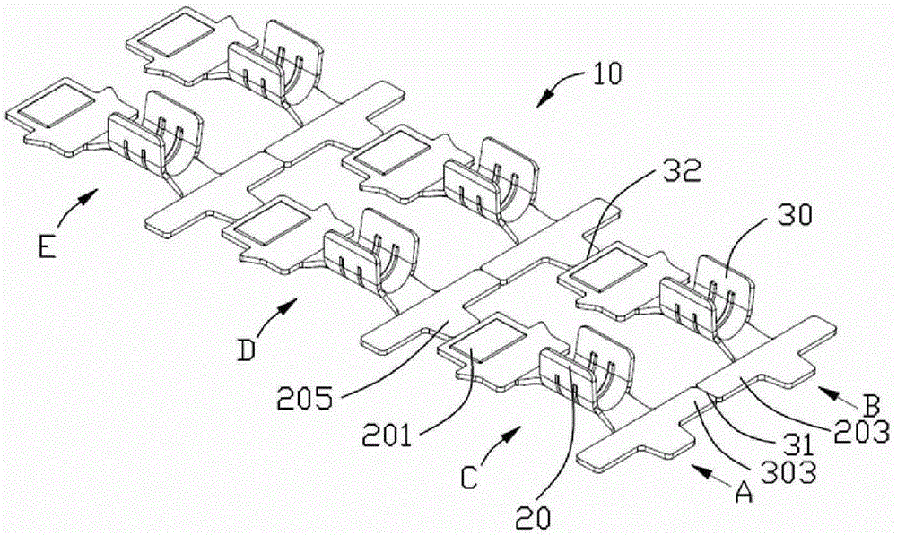
图4是图2所示导电端子的料带结构示意图。FIG. 4 is a schematic diagram of the strip structure of the conductive terminal shown in FIG. 2 .
【具体实施方式】 【Detailed ways】
请参照图1所示,本发明线缆连接器组件100包括导电端子20,30、线缆40、包覆所述导电端子20、30和线缆40的绝缘本体50及组装于绝缘本体50中且将所述组装好的导电端子20、30及线缆40卡固于所述绝缘本体50中的卡持块60。Referring to FIG. 1, the cable connector assembly 100 of the present invention includes
请参照图3所示,本发明端子料带10通过冲压成型步骤,在端子料带10上形成导电端子20,所述导电端子20包括主体部201(对接部)、自所述主体部201向后延伸形成的导体夹持部202(第一压接部)及自所述导体夹持部202向后延伸形成的绝缘夹持部203(第二压接部),所述绝缘夹持部203的中间部向后延伸形成有突出部205,所述主体部201上设有将所述导电端子20固定于连接器本体(未图示)中的倒刺204。Please refer to FIG. 3 , the
在冲压成型过程中,图3所示的端子料带10可包含多根不同的料带,为多排多列结构,端子料带10包括分别沿前后方向排列的两列料带A和B或者可看成分别沿横向排列的三排料带C、D、E。在这两列料带A和B上分别冲压形成若干导电端子20、30,所述导电端子30的结构与导电端子20的结构一致,位于同一料带C上的导电端子20、30的绝缘夹持部203、303相互连接,充当料带C的导引带。在本实施例中,以导电端子20为例,此时导电端子20又于前后方向上通过其主体部201与位于其前方导电端子的突出部205彼此相连于其纵向方向形成料带B,此时突出部205充当料带B的导引带。During the stamping and forming process, the
冲压完成后,所述冲压形成相邻的导电端子20、30之间相互连接,且彼此之间形成有第一压痕31、第二压痕32,沿所述第一压痕31、第二压痕32弯折可方便的将所述导电端子20、30彼此分离开。After the stamping is completed, the stamping forms the connection between the adjacent
请参照图2所示,以弯折分开后的导电端子20为例,所述导电端子20的导体夹持部202分别与相应的线缆40的导体400相压接以达到导电端子20与所述线缆40之间的电性连接,导电端子的绝缘夹持部203压接于线缆40的绝缘外层。组装完成后的导电端子20及线缆40组装到绝缘本体50中,且通过卡持块60的卡持可将所述组装好的导电端子20及线缆40卡持在所述卡持块60的侧槽601中,所述线缆连接器组件100的前端还设有一椭圆形本体70,以所述线缆连接器组件100为一圣诞灯为例,所述椭圆形本体70中安装有发光体(未图示),所述椭圆形本体70与所述发光体(未图示)组装完后一起组装到所述绝缘本体50中,且使得所述发光体(未图示)的后端与所述导电端子的主体部201相电性连接。Please refer to FIG. 2 , taking the
在上述所得到的线缆连接器组件主要涉及到以下制造步骤:第一步:提供端子料带,为多排多列结构,所述端子料带中的每个端子包括主体部、第一压接部及第二压接部,每列料带间通过相邻两个端子的第二压接部相互连接,所述连接处形成有第一压痕,每排料带间通过前后两个端子的主体部和第二压接部首尾相连,所述连接处形成有第二压痕;第二步:切断端子料带,通过切断第一压痕和第二压痕以得到单个导电端子;第三步:连接导电端子和线缆,所述线缆包括导体及包覆导体的绝缘外层,所述第一压接部与导体相压接,所述第二压接部与绝缘外层相压接。The cable connector assembly obtained above mainly involves the following manufacturing steps: Step 1: Provide terminal strips, which are multi-row and multi-column structures, and each terminal in the terminal strips includes a main body, a first press The connecting part and the second crimping part, each row of material strips are connected to each other through the second crimping part of two adjacent terminals, the first indentation is formed at the connection, and the front and rear terminals are passed between each row of material strips The main body and the second crimping part are connected end to end, and the connection is formed with a second indentation; the second step: cutting off the terminal strip, and obtaining a single conductive terminal by cutting off the first indentation and the second indentation; the second Three steps: connect the conductive terminal and the cable, the cable includes a conductor and an insulating outer layer covering the conductor, the first crimping part is crimped with the conductor, and the second crimping part is connected with the insulating outer layer Crimp.
本发明中由于端子料带10所冲压形成的导电端子20、30结构的特殊性,在冲压过程中,导电端子20、30的绝缘固持部203、303彼此相连形成端子沿横向排列的料带C、D、E,导电端子20及导电端子30分别沿前后方向首尾相连形成料带A和料带B,在本实施例中,由于料带A、B、C、D、E均由导电端子本身的结构来充当导引带,故减少了另外成型导引带所产生的废料,可以降低成型导电端子的端子料带的制造成本,符合现代生产的需求。In the present invention, due to the particularity of the structure of the
以上仅为本发明所举的一种导电端子的具体实施方案,其他利用本发明的方法所制造出的其它导电端子也应当不脱离本发明的技术方案。The above is only a specific embodiment of a conductive terminal in the present invention, and other conductive terminals manufactured by the method of the present invention should not deviate from the technical solution of the present invention.
Claims (6)
Priority Applications (1)
| Application Number | Priority Date | Filing Date | Title |
|---|---|---|---|
| CN2009103022980A CN101888024B (en) | 2009-05-14 | 2009-05-14 | Cable connector assembly, manufacturing method thereof, conduction terminal and strip thereof |
Applications Claiming Priority (1)
| Application Number | Priority Date | Filing Date | Title |
|---|---|---|---|
| CN2009103022980A CN101888024B (en) | 2009-05-14 | 2009-05-14 | Cable connector assembly, manufacturing method thereof, conduction terminal and strip thereof |
Publications (2)
| Publication Number | Publication Date |
|---|---|
| CN101888024A CN101888024A (en) | 2010-11-17 |
| CN101888024B true CN101888024B (en) | 2012-11-28 |
Family
ID=43073807
Family Applications (1)
| Application Number | Title | Priority Date | Filing Date |
|---|---|---|---|
| CN2009103022980A Expired - Fee Related CN101888024B (en) | 2009-05-14 | 2009-05-14 | Cable connector assembly, manufacturing method thereof, conduction terminal and strip thereof |
Country Status (1)
| Country | Link |
|---|---|
| CN (1) | CN101888024B (en) |
Families Citing this family (3)
| Publication number | Priority date | Publication date | Assignee | Title |
|---|---|---|---|---|
| CN103972721B (en) * | 2013-02-05 | 2016-03-09 | 凡甲电子(苏州)有限公司 | cable connector |
| JP5579341B1 (en) | 2013-02-22 | 2014-08-27 | 古河電気工業株式会社 | Terminal connection band, crimp terminal manufacturing method, wire crimping device, and wire crimping method |
| CN110190445A (en) * | 2018-02-23 | 2019-08-30 | 泰科电子(上海)有限公司 | Housings and electrical protectors for electronic components |
-
2009
- 2009-05-14 CN CN2009103022980A patent/CN101888024B/en not_active Expired - Fee Related
Non-Patent Citations (6)
| Title |
|---|
| JP昭55-157883A 1980.12.08 |
| JP昭55-30160A 1980.03.03 |
| JP特开2008-103140A 2008.05.01 |
| JP特开2008-123841A 2008.05.29 |
| JP特开2008-84630A 2008.04.10 |
| JP特开平6-36817A 1994.02.10 |
Also Published As
| Publication number | Publication date |
|---|---|
| CN101888024A (en) | 2010-11-17 |
Similar Documents
| Publication | Publication Date | Title |
|---|---|---|
| US7833045B2 (en) | Insulation displacement connector (IDC) | |
| CN105229859B (en) | Band terminal wires | |
| CN111384611B (en) | Electrical connector and manufacturing method thereof | |
| US3867005A (en) | Insulation-piercing contact member and electrical connector | |
| JP5244427B2 (en) | Electronic component mounting / insulator-integrated inner conductor terminals and coaxial connectors | |
| JP6820290B2 (en) | Connection terminal and terminal connection structure | |
| US20110250783A1 (en) | Cable assembly with improved terminating means and method of making the same | |
| JP2015167225A5 (en) | ||
| JP2018147828A (en) | Crimp connection terminal and method of connecting the crimp connection terminal | |
| JP2020071920A (en) | Crimp connection terminal | |
| US6453552B1 (en) | Method of manufacturing electrical terminals and terminal modules | |
| CN101888024B (en) | Cable connector assembly, manufacturing method thereof, conduction terminal and strip thereof | |
| CN201667396U (en) | Cable Connector Assembly | |
| CN102148430A (en) | Cable connector assembly and manufacturing method thereof | |
| JP5798840B2 (en) | Connecting terminal | |
| TWM332290U (en) | Electrical connector | |
| JP6744975B1 (en) | Crimp connection terminal | |
| CN204376028U (en) | Idc connector male head | |
| TWI426669B (en) | Cable connector assembly and the manufacturing method thereof, contacts and carrier thereof | |
| CN107591664A (en) | The manufacture method of conducting terminal | |
| US7001203B2 (en) | Piercing terminal for coaxial cable | |
| US10680394B2 (en) | Electrical connector having a contact with upper and lower contacting portions | |
| JP3900473B2 (en) | Piercing terminal connection structure | |
| JP6506876B1 (en) | Crimp connection terminal | |
| CN106329220B (en) | Manufacturing method of flat cable connecting terminal |
Legal Events
| Date | Code | Title | Description |
|---|---|---|---|
| C06 | Publication | ||
| PB01 | Publication | ||
| C10 | Entry into substantive examination | ||
| SE01 | Entry into force of request for substantive examination | ||
| C14 | Grant of patent or utility model | ||
| GR01 | Patent grant | ||
| C17 | Cessation of patent right | ||
| CF01 | Termination of patent right due to non-payment of annual fee |
Granted publication date: 20121128 Termination date: 20130514 |