CN101902004A - Lamp socket and the contact that is used for described socket - Google Patents
Lamp socket and the contact that is used for described socket Download PDFInfo
- Publication number
- CN101902004A CN101902004A CN2010101317699A CN201010131769A CN101902004A CN 101902004 A CN101902004 A CN 101902004A CN 2010101317699 A CN2010101317699 A CN 2010101317699A CN 201010131769 A CN201010131769 A CN 201010131769A CN 101902004 A CN101902004 A CN 101902004A
- Authority
- CN
- China
- Prior art keywords
- contact
- socket
- lead
- lamp
- longitudinal axis
- Prior art date
- Legal status (The legal status is an assumption and is not a legal conclusion. Google has not performed a legal analysis and makes no representation as to the accuracy of the status listed.)
- Pending
Links
- PXHVJJICTQNCMI-UHFFFAOYSA-N Nickel Chemical group [Ni] PXHVJJICTQNCMI-UHFFFAOYSA-N 0.000 claims description 4
- 239000000463 material Substances 0.000 claims description 4
- 229910052759 nickel Inorganic materials 0.000 claims description 2
- 229910001220 stainless steel Inorganic materials 0.000 claims description 2
- 239000010935 stainless steel Substances 0.000 claims description 2
- 230000005611 electricity Effects 0.000 description 4
- 238000009434 installation Methods 0.000 description 3
- 239000000919 ceramic Substances 0.000 description 2
- 229910010293 ceramic material Inorganic materials 0.000 description 2
- 230000007812 deficiency Effects 0.000 description 1
- 230000004048 modification Effects 0.000 description 1
- 238000012986 modification Methods 0.000 description 1
- 230000002787 reinforcement Effects 0.000 description 1
- 229910052623 talc Inorganic materials 0.000 description 1
- 235000012222 talc Nutrition 0.000 description 1
- 239000000454 talc Substances 0.000 description 1
Images


Classifications
-
- H—ELECTRICITY
- H01—ELECTRIC ELEMENTS
- H01R—ELECTRICALLY-CONDUCTIVE CONNECTIONS; STRUCTURAL ASSOCIATIONS OF A PLURALITY OF MUTUALLY-INSULATED ELECTRICAL CONNECTING ELEMENTS; COUPLING DEVICES; CURRENT COLLECTORS
- H01R33/00—Coupling devices specially adapted for supporting apparatus and having one part acting as a holder providing support and electrical connection via a counterpart which is structurally associated with the apparatus, e.g. lamp holders; Separate parts thereof
- H01R33/05—Two-pole devices
-
- H—ELECTRICITY
- H01—ELECTRIC ELEMENTS
- H01R—ELECTRICALLY-CONDUCTIVE CONNECTIONS; STRUCTURAL ASSOCIATIONS OF A PLURALITY OF MUTUALLY-INSULATED ELECTRICAL CONNECTING ELEMENTS; COUPLING DEVICES; CURRENT COLLECTORS
- H01R13/00—Details of coupling devices of the kinds covered by groups H01R12/70 or H01R24/00 - H01R33/00
- H01R13/02—Contact members
- H01R13/10—Sockets for co-operation with pins or blades
- H01R13/11—Resilient sockets
- H01R13/112—Resilient sockets forked sockets having two legs
-
- H—ELECTRICITY
- H01—ELECTRIC ELEMENTS
- H01R—ELECTRICALLY-CONDUCTIVE CONNECTIONS; STRUCTURAL ASSOCIATIONS OF A PLURALITY OF MUTUALLY-INSULATED ELECTRICAL CONNECTING ELEMENTS; COUPLING DEVICES; CURRENT COLLECTORS
- H01R13/00—Details of coupling devices of the kinds covered by groups H01R12/70 or H01R24/00 - H01R33/00
- H01R13/02—Contact members
- H01R13/15—Pins, blades or sockets having separate spring member for producing or increasing contact pressure
- H01R13/18—Pins, blades or sockets having separate spring member for producing or increasing contact pressure with the spring member surrounding the socket
-
- H—ELECTRICITY
- H01—ELECTRIC ELEMENTS
- H01R—ELECTRICALLY-CONDUCTIVE CONNECTIONS; STRUCTURAL ASSOCIATIONS OF A PLURALITY OF MUTUALLY-INSULATED ELECTRICAL CONNECTING ELEMENTS; COUPLING DEVICES; CURRENT COLLECTORS
- H01R13/00—Details of coupling devices of the kinds covered by groups H01R12/70 or H01R24/00 - H01R33/00
- H01R13/46—Bases; Cases
- H01R13/502—Bases; Cases composed of different pieces
-
- H—ELECTRICITY
- H01—ELECTRIC ELEMENTS
- H01R—ELECTRICALLY-CONDUCTIVE CONNECTIONS; STRUCTURAL ASSOCIATIONS OF A PLURALITY OF MUTUALLY-INSULATED ELECTRICAL CONNECTING ELEMENTS; COUPLING DEVICES; CURRENT COLLECTORS
- H01R33/00—Coupling devices specially adapted for supporting apparatus and having one part acting as a holder providing support and electrical connection via a counterpart which is structurally associated with the apparatus, e.g. lamp holders; Separate parts thereof
- H01R33/05—Two-pole devices
- H01R33/46—Two-pole devices for bayonet type base
-
- H—ELECTRICITY
- H01—ELECTRIC ELEMENTS
- H01R—ELECTRICALLY-CONDUCTIVE CONNECTIONS; STRUCTURAL ASSOCIATIONS OF A PLURALITY OF MUTUALLY-INSULATED ELECTRICAL CONNECTING ELEMENTS; COUPLING DEVICES; CURRENT COLLECTORS
- H01R4/00—Electrically-conductive connections between two or more conductive members in direct contact, i.e. touching one another; Means for effecting or maintaining such contact; Electrically-conductive connections having two or more spaced connecting locations for conductors and using contact members penetrating insulation
- H01R4/28—Clamped connections, spring connections
- H01R4/30—Clamped connections, spring connections utilising a screw or nut clamping member
- H01R4/36—Conductive members located under tip of screw
Landscapes
- Connecting Device With Holders (AREA)
- Fastening Of Light Sources Or Lamp Holders (AREA)
- Non-Portable Lighting Devices Or Systems Thereof (AREA)
Abstract
本发明涉及灯插座和用于所述插座的触头。插座用于收容和保持灯且提供电连接到灯的电引入件上,电引入件从灯沿与纵轴线正交的方向伸出。插座包括第一本体部分,其围绕纵轴线布置且包括与纵轴线对准用于收容灯的一部分的收容部。引入件收容部形成在插座本体中,相对于纵轴线横向地设置。电引入触头接收部形成为邻近引入件收容部。径向间隔开的触头保持部与触头接收部相关联。电触头定位在各触头接收部中,包括由弓形部连结的间隔开的第一和第二接合体。一突出部从第一接合体远端延伸且限定在触头保持部中,且另一突出部从第二接合体近端延伸。第二本体部分附连到第一本体部分上,且触头保持弹簧定位在第二本体部分的内表面与第一引入件接合体之间。
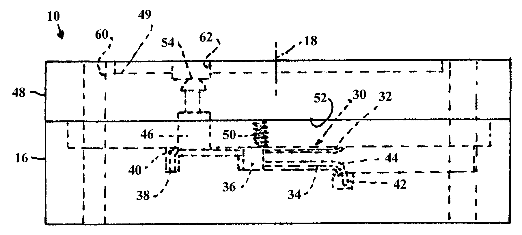
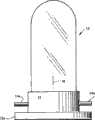
The invention relates to lamp sockets and contacts for said sockets. A socket is used to receive and hold the lamp and to provide electrical connection to an electrical lead-in of the lamp, which projects from the lamp in a direction orthogonal to the longitudinal axis. The socket includes a first body portion disposed about the longitudinal axis and including a receptacle aligned with the longitudinal axis for receiving a portion of the lamp. A lead-in receptacle is formed in the socket body disposed transversely with respect to the longitudinal axis. An electrical lead-in contact receiving portion is formed adjacent to the lead-in receiving portion. Radially spaced apart contact holders are associated with the contact receivers. An electrical contact is positioned within each contact-receiving portion and includes first and second spaced apart engagement bodies joined by an arcuate portion. A protrusion extends from the distal end of the first engagement body and is defined in the contact holding portion, and another protrusion extends from the proximal end of the second engagement body. The second body portion is attached to the first body portion, and the contact retaining spring is positioned between the inner surface of the second body portion and the first lead-in engagement body.
Description
Claims (4)
Applications Claiming Priority (2)
| Application Number | Priority Date | Filing Date | Title |
|---|---|---|---|
| US12/380,218 US7731545B1 (en) | 2009-02-25 | 2009-02-25 | Lamp socket and contact for said socket |
| US12/380218 | 2009-02-25 |
Publications (1)
| Publication Number | Publication Date |
|---|---|
| CN101902004A true CN101902004A (en) | 2010-12-01 |
Family
ID=42101286
Family Applications (1)
| Application Number | Title | Priority Date | Filing Date |
|---|---|---|---|
| CN2010101317699A Pending CN101902004A (en) | 2009-02-25 | 2010-02-23 | Lamp socket and the contact that is used for described socket |
Country Status (4)
| Country | Link |
|---|---|
| US (1) | US7731545B1 (en) |
| EP (1) | EP2224555B1 (en) |
| CN (1) | CN101902004A (en) |
| AT (1) | ATE525774T1 (en) |
Families Citing this family (4)
| Publication number | Priority date | Publication date | Assignee | Title |
|---|---|---|---|---|
| US7993162B1 (en) | 2010-05-06 | 2011-08-09 | Osram Sylvania Inc. | Lamp socket having contact and backup spring |
| US9306327B1 (en) * | 2015-04-17 | 2016-04-05 | Osram Sylvania Inc. | Clip for wire harness |
| US10431907B2 (en) * | 2017-12-22 | 2019-10-01 | Eaton Intelligent Power Limited | Connection apparatus and electrical receptacle |
| US12224541B2 (en) * | 2021-06-08 | 2025-02-11 | International Business Machines Corporation | Structure for fastening verification |
Citations (22)
| Publication number | Priority date | Publication date | Assignee | Title |
|---|---|---|---|---|
| GB528943A (en) * | 1939-05-17 | 1940-11-11 | Vickers Train Lighting Company | Improvements in or relating to electric lamp fittings with lamp locking devices |
| GB707506A (en) * | 1951-05-28 | 1954-04-21 | Philips Electrical Ind Ltd | Improvements in or relating to bayonet type electric lamp holders |
| GB850069A (en) * | 1958-12-15 | 1960-09-28 | Hubbell Inc Harvey | Electrical plug and socket connector device |
| JPS5780655A (en) * | 1980-10-31 | 1982-05-20 | Duro Test Corp | Baseless incandescent lamp |
| US4899266A (en) * | 1984-10-24 | 1990-02-06 | Ahroni Joseph M | Miniature light sets and lampholders and method for making them |
| US5924882A (en) * | 1998-01-05 | 1999-07-20 | Slazakowski; Kenneth A. | Front mounting socket for a gas light tube |
| CN1238582A (en) * | 1998-02-25 | 1999-12-15 | 住友电装株式会社 | Connecting structure for bulb socket and electric wire |
| US6045387A (en) * | 1997-04-11 | 2000-04-04 | Bender & Wirth Gmbh & Co. | Socket for two-pin lamps |
| JP3159740B2 (en) * | 1990-09-26 | 2001-04-23 | コーニンクレッカ フィリップス エレクトロニクス エヌ ヴィ | High pressure discharge lamp with cap |
| JP3272758B2 (en) * | 1991-02-28 | 2002-04-08 | コーニンクレッカ フィリップス エレクトロニクス エヌ ヴィ | Lamp with cap working at home supply voltage and unit suitable for use with this lamp |
| CN1358322A (en) * | 1999-12-17 | 2002-07-10 | 皇家菲利浦电子有限公司 | Combination of lamp base, wick and lamp base, and fixing method of lamp |
| CN1419644A (en) * | 2001-01-30 | 2003-05-21 | 皇家菲利浦电子有限公司 | Electric lamp provided with a lamp cap |
| US20040032738A1 (en) * | 2000-08-09 | 2004-02-19 | Friedhelm Harnischmacher | Lamp |
| CN1612992A (en) * | 2002-01-02 | 2005-05-04 | 皇家飞利浦电子股份有限公司 | Easy-to-install lamps and headlamps |
| US7025634B1 (en) * | 2005-05-16 | 2006-04-11 | Osram Sylvania Inc. | Lamp socket |
| US7080923B2 (en) * | 2002-11-30 | 2006-07-25 | Genlyte Thomas Group, Llc | Surface mount fluorescent strip light fixture retrofit kit and method |
| US7097489B2 (en) * | 2004-02-20 | 2006-08-29 | Tekcon Electronics Corp. | HID lamp socket |
| CN1849731A (en) * | 2003-09-05 | 2006-10-18 | 皇家飞利浦电子股份有限公司 | Lighting unit, holder, lamp and luminaire |
| US7222987B2 (en) * | 2005-05-13 | 2007-05-29 | Wei-Jen Tseng | Connector for connecting light strings |
| CN101015098A (en) * | 2004-09-10 | 2007-08-08 | E.M.C.科洛西奥股份公司 | Lamp holding device |
| JP2008103338A (en) * | 2006-10-19 | 2008-05-01 | Osram Sylvania Inc | Front or rear mounting socket system |
| US7399191B1 (en) * | 2007-11-06 | 2008-07-15 | Osram Sylvania Inc. | Socket body |
Family Cites Families (5)
| Publication number | Priority date | Publication date | Assignee | Title |
|---|---|---|---|---|
| US4256989A (en) | 1978-09-22 | 1981-03-17 | Duro Test Corporation | Incandescent lamp with filament mounting means and socket adaptor |
| DE3371840D1 (en) | 1982-08-09 | 1987-07-02 | Kudos Lighting Ltd | Lampholder |
| DE9010572U1 (en) * | 1990-07-13 | 1990-10-04 | Patent-Treuhand-Gesellschaft für elektrische Glühlampen mbH, 81543 München | Socket for a single-ended high-pressure discharge lamp |
| US6162079A (en) | 1998-01-05 | 2000-12-19 | Slazakowski; Kenneth A. | Front mounting socket for a gas tube light |
| US7637649B2 (en) | 2006-10-19 | 2009-12-29 | Osram Sylvania Inc. | Reversible lamp |
-
2009
- 2009-02-25 US US12/380,218 patent/US7731545B1/en active Active
-
2010
- 2010-02-03 EP EP10152492A patent/EP2224555B1/en not_active Not-in-force
- 2010-02-03 AT AT10152492T patent/ATE525774T1/en not_active IP Right Cessation
- 2010-02-23 CN CN2010101317699A patent/CN101902004A/en active Pending
Patent Citations (22)
| Publication number | Priority date | Publication date | Assignee | Title |
|---|---|---|---|---|
| GB528943A (en) * | 1939-05-17 | 1940-11-11 | Vickers Train Lighting Company | Improvements in or relating to electric lamp fittings with lamp locking devices |
| GB707506A (en) * | 1951-05-28 | 1954-04-21 | Philips Electrical Ind Ltd | Improvements in or relating to bayonet type electric lamp holders |
| GB850069A (en) * | 1958-12-15 | 1960-09-28 | Hubbell Inc Harvey | Electrical plug and socket connector device |
| JPS5780655A (en) * | 1980-10-31 | 1982-05-20 | Duro Test Corp | Baseless incandescent lamp |
| US4899266A (en) * | 1984-10-24 | 1990-02-06 | Ahroni Joseph M | Miniature light sets and lampholders and method for making them |
| JP3159740B2 (en) * | 1990-09-26 | 2001-04-23 | コーニンクレッカ フィリップス エレクトロニクス エヌ ヴィ | High pressure discharge lamp with cap |
| JP3272758B2 (en) * | 1991-02-28 | 2002-04-08 | コーニンクレッカ フィリップス エレクトロニクス エヌ ヴィ | Lamp with cap working at home supply voltage and unit suitable for use with this lamp |
| US6045387A (en) * | 1997-04-11 | 2000-04-04 | Bender & Wirth Gmbh & Co. | Socket for two-pin lamps |
| US5924882A (en) * | 1998-01-05 | 1999-07-20 | Slazakowski; Kenneth A. | Front mounting socket for a gas light tube |
| CN1238582A (en) * | 1998-02-25 | 1999-12-15 | 住友电装株式会社 | Connecting structure for bulb socket and electric wire |
| CN1358322A (en) * | 1999-12-17 | 2002-07-10 | 皇家菲利浦电子有限公司 | Combination of lamp base, wick and lamp base, and fixing method of lamp |
| US20040032738A1 (en) * | 2000-08-09 | 2004-02-19 | Friedhelm Harnischmacher | Lamp |
| CN1419644A (en) * | 2001-01-30 | 2003-05-21 | 皇家菲利浦电子有限公司 | Electric lamp provided with a lamp cap |
| CN1612992A (en) * | 2002-01-02 | 2005-05-04 | 皇家飞利浦电子股份有限公司 | Easy-to-install lamps and headlamps |
| US7080923B2 (en) * | 2002-11-30 | 2006-07-25 | Genlyte Thomas Group, Llc | Surface mount fluorescent strip light fixture retrofit kit and method |
| CN1849731A (en) * | 2003-09-05 | 2006-10-18 | 皇家飞利浦电子股份有限公司 | Lighting unit, holder, lamp and luminaire |
| US7097489B2 (en) * | 2004-02-20 | 2006-08-29 | Tekcon Electronics Corp. | HID lamp socket |
| CN101015098A (en) * | 2004-09-10 | 2007-08-08 | E.M.C.科洛西奥股份公司 | Lamp holding device |
| US7222987B2 (en) * | 2005-05-13 | 2007-05-29 | Wei-Jen Tseng | Connector for connecting light strings |
| US7025634B1 (en) * | 2005-05-16 | 2006-04-11 | Osram Sylvania Inc. | Lamp socket |
| JP2008103338A (en) * | 2006-10-19 | 2008-05-01 | Osram Sylvania Inc | Front or rear mounting socket system |
| US7399191B1 (en) * | 2007-11-06 | 2008-07-15 | Osram Sylvania Inc. | Socket body |
Also Published As
| Publication number | Publication date |
|---|---|
| US7731545B1 (en) | 2010-06-08 |
| ATE525774T1 (en) | 2011-10-15 |
| EP2224555B1 (en) | 2011-09-21 |
| EP2224555A1 (en) | 2010-09-01 |
Similar Documents
| Publication | Publication Date | Title |
|---|---|---|
| CN203810108U (en) | Straight lamp and lighting device | |
| US10243292B2 (en) | Holder assembly | |
| US20220013945A1 (en) | Connector | |
| TWI463741B (en) | Power receptacle for portable electronic device | |
| TW200941849A (en) | Right-angle connector | |
| CN101902004A (en) | Lamp socket and the contact that is used for described socket | |
| CN103782093A (en) | Light-emitting means and use | |
| US20150244090A1 (en) | Circuit board connector | |
| DK2345840T3 (en) | LAMP CONNECTION CLIPS | |
| US10938126B2 (en) | Wire connector | |
| CN105990715A (en) | Power connector | |
| CN210443684U (en) | Electric contact device and electric power track | |
| US8167663B1 (en) | Laterally-plugged power connector | |
| CN216354907U (en) | Handheld electric connector | |
| CN201112607Y (en) | connector structure | |
| JP2015011891A (en) | Socket and lighting fixture employing the same | |
| CN206595530U (en) | An electrical connection device between linear light modules | |
| JP5579486B2 (en) | Screw tightening method for one electric wire using one combination terminal | |
| KR20120002276U (en) | Outlet with pressure port | |
| EP3826117A1 (en) | Replacement contact-tip for an electrical contact of a connector | |
| JP5757623B2 (en) | Terminal fittings and valve sockets | |
| CN114156669B (en) | Power connector and its support base | |
| TW200929746A (en) | Lamp socket, discharge lamp unit and luminescent device | |
| CN101782227B (en) | LED socket connector and LED module | |
| TWI543497B (en) | Plug-in carbon brush holder and conductor terminal assembly |
Legal Events
| Date | Code | Title | Description |
|---|---|---|---|
| C06 | Publication | ||
| PB01 | Publication | ||
| C10 | Entry into substantive examination | ||
| SE01 | Entry into force of request for substantive examination | ||
| AD01 | Patent right deemed abandoned | ||
| AD01 | Patent right deemed abandoned |
Effective date of abandoning: 20101201 |