CN101968367A - Multifunctional networking digital shaft angle converter and converting method thereof - Google Patents
Multifunctional networking digital shaft angle converter and converting method thereof Download PDFInfo
- Publication number
- CN101968367A CN101968367A CN2010101490669A CN201010149066A CN101968367A CN 101968367 A CN101968367 A CN 101968367A CN 2010101490669 A CN2010101490669 A CN 2010101490669A CN 201010149066 A CN201010149066 A CN 201010149066A CN 101968367 A CN101968367 A CN 101968367A
- Authority
- CN
- China
- Prior art keywords
- interface
- circuit
- conversion
- angle
- bus
- Prior art date
- Legal status (The legal status is an assumption and is not a legal conclusion. Google has not performed a legal analysis and makes no representation as to the accuracy of the status listed.)
- Pending
Links
- 238000000034 method Methods 0.000 title claims abstract description 12
- 230000006855 networking Effects 0.000 title abstract description 3
- 238000006243 chemical reaction Methods 0.000 claims abstract description 55
- 238000004891 communication Methods 0.000 claims description 12
- 238000012545 processing Methods 0.000 claims description 10
- 230000005284 excitation Effects 0.000 claims description 9
- 238000005259 measurement Methods 0.000 claims description 6
- 230000010354 integration Effects 0.000 claims description 5
- 230000009466 transformation Effects 0.000 claims description 5
- 230000008569 process Effects 0.000 claims description 4
- 238000011426 transformation method Methods 0.000 claims description 2
- 230000006870 function Effects 0.000 abstract description 9
- 230000006698 induction Effects 0.000 abstract description 3
- 230000008571 general function Effects 0.000 abstract description 2
- 238000010586 diagram Methods 0.000 description 6
- 238000013461 design Methods 0.000 description 5
- 239000003990 capacitor Substances 0.000 description 4
- 238000001514 detection method Methods 0.000 description 3
- 230000005540 biological transmission Effects 0.000 description 2
- 230000003139 buffering effect Effects 0.000 description 2
- 238000005516 engineering process Methods 0.000 description 2
- 238000001914 filtration Methods 0.000 description 2
- 230000010365 information processing Effects 0.000 description 2
- 230000002093 peripheral effect Effects 0.000 description 2
- 230000008901 benefit Effects 0.000 description 1
- 239000000919 ceramic Substances 0.000 description 1
- 239000013078 crystal Substances 0.000 description 1
- 230000007274 generation of a signal involved in cell-cell signaling Effects 0.000 description 1
- 230000001939 inductive effect Effects 0.000 description 1
- 238000012986 modification Methods 0.000 description 1
- 230000004048 modification Effects 0.000 description 1
- 230000010355 oscillation Effects 0.000 description 1
- 239000010453 quartz Substances 0.000 description 1
- 238000011160 research Methods 0.000 description 1
- 238000005070 sampling Methods 0.000 description 1
- VYPSYNLAJGMNEJ-UHFFFAOYSA-N silicon dioxide Inorganic materials O=[Si]=O VYPSYNLAJGMNEJ-UHFFFAOYSA-N 0.000 description 1
- 238000012360 testing method Methods 0.000 description 1
Images



Classifications
-
- Y—GENERAL TAGGING OF NEW TECHNOLOGICAL DEVELOPMENTS; GENERAL TAGGING OF CROSS-SECTIONAL TECHNOLOGIES SPANNING OVER SEVERAL SECTIONS OF THE IPC; TECHNICAL SUBJECTS COVERED BY FORMER USPC CROSS-REFERENCE ART COLLECTIONS [XRACs] AND DIGESTS
- Y02—TECHNOLOGIES OR APPLICATIONS FOR MITIGATION OR ADAPTATION AGAINST CLIMATE CHANGE
- Y02P—CLIMATE CHANGE MITIGATION TECHNOLOGIES IN THE PRODUCTION OR PROCESSING OF GOODS
- Y02P90/00—Enabling technologies with a potential contribution to greenhouse gas [GHG] emissions mitigation
- Y02P90/02—Total factory control, e.g. smart factories, flexible manufacturing systems [FMS] or integrated manufacturing systems [IMS]
Landscapes
- Arrangements For Transmission Of Measured Signals (AREA)
- Transmission And Conversion Of Sensor Element Output (AREA)
Abstract
本发明提供的是多功能网络化数字轴角变换器及变换方法。PC机通过串口电平转换电路与TMS320F2808数字控制器连接,通过上位机软件完成初始硬件及软件设定;完成初始定并连接好硬件之后,角位置传感器和TMS320F2808数字控制器通过传感器接口及缓冲电路传递信息,并在TMS320F2808数字控制器中完成轴角转换运算,运算得到的结果由并行数据输出电路传给控制电路板、或通过485及CAN总线接口作为工业控制网络节点传递到工业总线上。本发明能够简化装置结构,降低成本;具有通用功能,能够实现多种轴角传感器接口,通过功能选择软件可以实现感应同步器、旋转变压器以及光电码盘的接口与转换;可以实现基于常用工业现场总线的接口,具备多功能网络化的特点。

The invention provides a multifunctional networked digital shaft-angle converter and a conversion method. The PC is connected to the TMS320F2808 digital controller through the serial port level conversion circuit, and the initial hardware and software settings are completed through the host computer software; Transfer information, and complete the axis angle conversion operation in the TMS320F2808 digital controller. The result obtained by the operation is transmitted to the control circuit board by the parallel data output circuit, or transmitted to the industrial bus as an industrial control network node through the 485 and CAN bus interface. The invention can simplify the structure of the device and reduce the cost; it has general functions and can realize a variety of shaft angle sensor interfaces, and can realize the interface and conversion of the induction synchronizer, the rotary transformer and the photoelectric code disc through the function selection software; The interface of the bus has the characteristics of multi-functional networking.
Description
技术领域technical field
本发明涉及传感器处理及检测技术,特别是基于数字处理器实现的旋转编码器及正余弦编码器的数字转化技术。The invention relates to a sensor processing and detection technology, in particular to a digital conversion technology of a rotary encoder and a sine-cosine encoder realized based on a digital processor.
背景技术Background technique
在工业控制及检测中,角位置是一个非常重要的参数,常采用感应同步器、旋转变压器、自整角机以及光电码盘等作为角度传感元件,结合轴角变换器组成测角系统。In industrial control and detection, angular position is a very important parameter. Inductive synchronizers, resolvers, synchros, and photoelectric code discs are often used as angle sensing elements, combined with shaft-angle converters to form an angle measurement system.
轴角变换器的核心是如何对角度传感器信号进行处理,将传感器的信息转换为便于计算机及其它系统处理的数字量值。在测角系统中,以往大都采用模拟电路和数字电路结合的方式实现轴角变换器的设计。如采用专用芯片结合外部模拟电路,例如AD公司的AD2S8X,DDC公司的RDC-19220系列,它们将两路正交感应信号转换成数字角度值。采用采用模拟电路和数字电路结合的方式的优点是能达到高分辨率要求,缺点是外围元件较多、使用复杂其价格昂贵,如果模拟器件配置不对测角电路不能正常工作,极大地限制了它的应用范围。The core of the shaft-angle converter is how to process the angle sensor signal and convert the sensor information into a digital value that is easy for computers and other systems to process. In the angle measurement system, in the past, the design of the shaft-angle converter was mostly realized by combining the analog circuit and the digital circuit. For example, special-purpose chips combined with external analog circuits, such as AD2S8X of AD Company and RDC-19220 series of DDC Company, convert two quadrature induction signals into digital angle values. The advantage of using the combination of analog circuit and digital circuit is that it can meet the high-resolution requirements. The disadvantage is that there are many peripheral components, complex use and expensive price. If the analog device configuration is wrong, the angle measurement circuit cannot work normally, which greatly limits it. scope of application.
目前,工业现场智能化要求将网络功能集成到传感器中,使传感器能够作为一个相对独立并具有一定智能的单元通过网络传送检测信息并接收上位机的控制信息,成为网络化智能传感器。由于测试对象的复杂性和应用场合的实时性要求,系统要求轴角变换器具有较强的信息处理与传输能力。At present, the intelligentization of industrial sites requires the integration of network functions into sensors, so that sensors can be used as a relatively independent and intelligent unit to transmit detection information through the network and receive control information from the host computer, becoming a networked intelligent sensor. Due to the complexity of the test object and the real-time requirements of the application, the system requires the shaft-angle converter to have strong information processing and transmission capabilities.
为了满足轴角变化器网络化、智能化的要求,解决模拟电路和数字电路结合的方式应用限制,采用高性能处理器TMS320F2808实现具有电路简单、功能可以方便选择的具有多重网络接口能力的全数字轴角变换装置。In order to meet the networked and intelligent requirements of the shaft angle changer and solve the application limitations of the combination of analog circuits and digital circuits, the high-performance processor TMS320F2808 is used to realize the all-digital with simple circuit and multiple network interface capabilities that can be easily selected. Shaft angle conversion device.
经对现有的技术文献检索发现,CNKI数据库中有一篇与本发明主题相同或类似的文献报道,名为《永磁无刷直流电机直接转矩控制系统的设计研究》(湖南大学硕士论文,发表日2009.3.2),该文采用专用芯片结合外部模拟电路方式,与多功能网络化数字轴角变换器方式不同。Find through searching existing technical documents, there is a bibliographical report identical or similar with the subject of the present invention in the CNKI database, called " the design research of permanent magnet brushless DC motor direct torque control system " (Master's thesis of Hunan University, Published on March 2, 2009), this article uses a dedicated chip combined with an external analog circuit, which is different from the multi-functional networked digital axis-angle converter.
发明内容Contents of the invention
本发明的目的在于提供一种能够简化装置结构,降低成本;可以实现基于常用工业现场总线的接口,具备多功能网络化的多功能网络化数字轴角变换器。本发明的目的还在于提供一种多功能网络化数字轴角变换方法。The purpose of the present invention is to provide a multifunctional networked digital axis-angle converter capable of simplifying the structure of the device and reducing costs; capable of realizing interfaces based on common industrial field buses and having multifunctional networking. The object of the present invention is also to provide a multifunctional networked digital axis-angle transformation method.
本发明的目的是这样实现的:The purpose of the present invention is achieved like this:
多功能网络化数字轴角变换装置组成主要包括传感器接口缓冲电路2、TMS320F2808数字控制器3及串并型数据接口;串并型数据接口进一步包括并行数据输出电路4、串口电平转换电路5和485及CAN总线接口6;PC机8通过串口电平转换电路5与TMS320F2808数字控制器3连接,通过上位机8软件完成初始硬件及软件设定,包括设定轴角转换方式及硬件连接设定;完成初始定并连接好硬件之后,角位置传感器1和TMS320F2808数字控制器3通过传感器接口及缓冲电路2传递信息,并在TMS320F2808数字控制器3中完成轴角转换运算,运算得到的结果由并行数据输出电路4传给控制电路板7,或通过485及CAN总线接口6作为工业控制网络节点传递到工业总线9上,也可以通过串口电平转换电路5由上位PC机8监控程序读出。The multifunctional networked digital axis-angle conversion device mainly includes sensor
多功能网络化数字轴角变换方法为:上位PC机8进行硬件连接选择开关23完成硬件连接选择,同时进行CPU中央处理器16中的轴角转换方式选择;由TMS320F2808自带的PWM发生模块15产生高频脉冲信号经过滤波及缓冲电路22产生高频正弦波信号,高频正弦波信号输入到旋转变压器10中作为励磁信号使得旋转变压器10开始工作,正余弦编码器或旋转变压器10输出两路正交电压信号由差动接收器11引入装置,经比较器12处理形成粗测脉冲给TMS320F2808自带的QEP模块13进行积分,积分的结果给TMS320F2808的CPU模块16;模拟信号经过TMS320F2808白带的ADC模块14进行采样保持及转换处理形成数字电压信号给CPU模块16,CPU模块16进行轴角变换算法运算,得到实时的角位置与角速度信息,由多路接口向外部传递信息;CPU模块16通过自带的I/O模块17以并行数据接口方式或通过自带的SPI模块18完成通外部控制电路板类型电路连接,CPU模块16通过自带的通用异步串行接口A19以通用串口方式向上位PC机8的监控软件输出转换结果;对于总线类接口需求,先有上位PC机8通过软件设置网络地址,然后由白带的通用异步串行接口B20或自带的CAN通讯接口21经过485及CAN接口电平转换电路6完成电平接口转换,得到的结果放到工业总线9,由主站读取。The multifunctional networked digital axis angle conversion method is as follows: the
本发明提供了一套全数字轴角变换装置及方法,取代模拟和数字混合方案,能够简化装置结构,降低成本;该轴角变换装置具有通用功能,能够实现多种轴角传感器接口,通过功能选择软件可以实现感应同步器、旋转变压器以及光电码盘的接口与转换;带有智能网络处理功能,可以实现基于常用工业现场总线的接口,具备多功能网络化的特点。The invention provides a set of all-digital shaft-angle conversion device and method, which replaces the analog and digital mixed scheme, can simplify the structure of the device, and reduce costs; the shaft-angle conversion device has general functions, and can realize various shaft-angle sensor interfaces. Selecting software can realize the interface and conversion of induction synchronizer, resolver and photoelectric code disc; with intelligent network processing function, it can realize the interface based on common industrial field bus, and has the characteristics of multi-functional network.
本发明的主要特点体现在:Main features of the present invention are reflected in:
1、TMS320F2808芯片在电机的数字化控制方面具有处理性能更好、外设集成度更高、程序存储器更大、A/D转换速度更快等特点,是数字化信息处理理想的升级产品且具有低成本、低功耗、高性能的特点。1. The TMS320F2808 chip has the characteristics of better processing performance, higher peripheral integration, larger program memory, and faster A/D conversion speed in the digital control of the motor. It is an ideal upgrade product for digital information processing and has low cost. , low power consumption, high performance characteristics.
2、硬件连接规格型号同一连接方便,留有多种功能接口供选择,对于不同编码器可以共用同一类型的接插件。2. The same hardware connection specifications and models are convenient for connection, and there are multiple functional interfaces for selection, and the same type of connectors can be used for different encoders.
3、带有智能网络处理功能,可以实现基于常用工业现场总线的接口,具备多功能网络化的特点。3. With intelligent network processing function, it can realize the interface based on common industrial field bus, and has the characteristics of multi-functional network.
4、可以通过PC机进行功能选择,无需硬件上修改,完成多重功能的重新配置,通过I/O口控制模拟多路开关,进而选择外部复用电路如何连接。4. The function can be selected through the PC without modification on the hardware, the reconfiguration of multiple functions can be completed, the analog multi-channel switch can be controlled through the I/O port, and then how to connect the external multiplexing circuit can be selected.
5、可以作为工业网路节点,通过PC机设置地址,构成基于MODBUS或CAN总线的网路节点。5. It can be used as an industrial network node, and the address can be set through a PC to form a network node based on MODBUS or CAN bus.
6、可以升级TMS320F2808芯片的软件,增加装置的功能,或根据需要进行软件功能修订。6. The software of the TMS320F2808 chip can be upgraded, the functions of the device can be increased, or the software functions can be revised according to the needs.
附图说明Description of drawings
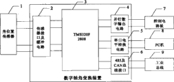
图1为多功能网络化数字轴角变换装置组成图;Figure 1 is a composition diagram of a multifunctional networked digital axis-angle conversion device;
图2为多功能网络化数字轴角变换装置运行原理图;Figure 2 is a schematic diagram of the operation of a multifunctional networked digital axis-angle conversion device;
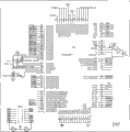
图3为多功能网络化数字轴角变换装置的TMS320F2808最小系统电路图;Fig. 3 is the minimum system circuit diagram of the TMS320F2808 of the multifunctional networked digital axis-angle conversion device;
图4为多功能网络化数字轴角变换装置的轴角变换部分的电路图;Fig. 4 is the circuit diagram of the shaft-angle transformation part of the multifunctional networked digital shaft-angle transformation device;
图5为多功能网络化数字轴角变换装置的外界通信接口的电路图。Fig. 5 is a circuit diagram of the external communication interface of the multifunctional networked digital axis-angle conversion device.
具体实施方式Detailed ways
下面结合附图举例对本发明做更详细地描述:The present invention is described in more detail below in conjunction with accompanying drawing example:
结合图1,本发明的为多功能网络化数字轴角变换装置组成包括:1-角位置传感器;2-传感器接口缓冲电路;3-TMS320F2808数字控制器;4-并行数字输出电路;5-串行接口电平转换电路;6-485及CAN接口电平转换电路;7-外部控制电路板;8-上位PC机;9-工业总线。In conjunction with Fig. 1, the composition of the present invention is a multifunctional networked digital shaft-angle conversion device comprising: 1-angular position sensor; 2-sensor interface buffer circuit; 3-TMS320F2808 digital controller; 4-parallel digital output circuit; 5-serial Line interface level conversion circuit; 6-485 and CAN interface level conversion circuit; 7-external control circuit board; 8-upper PC; 9-industrial bus.
图2为多功能网络化数字轴角变换装置运行原理,其中:10-正余弦编码器或旋转变压器等传感器;11-差动接收器;12-比较器;13-TMS320F2808自带的QEP模块;14-TMS320F2808自带的ADC模块;15-TMS320F2808自带的PWM发生模块;16-TMS320F2808的CPU模块;17-TMS320F2808白带的I/O模块;18-TMS320F2808自带的SPI接口;19-TMS320F2808自带的通用异步串行接口A;20-TMS320F2808自带的通用异步串行接口B;21-TMS320F2808自带的CAN通讯接口;22-滤波及缓冲电路;23-硬件连接选择开关。Figure 2 shows the operating principle of the multifunctional networked digital axis-angle conversion device, in which: 10-sensors such as sine-cosine encoder or resolver; 11-differential receiver; 12-comparator; 13-QEP module that comes with TMS320F2808; 14-ADC module of TMS320F2808; 15-PWM generation module of TMS320F2808; 16-CPU module of TMS320F2808; 17-I/O module of TMS320F2808 white belt; 18-SPI interface of TMS320F2808; 20-TMS320F2808’s own universal asynchronous serial interface B; 21-TMS320F2808’s own CAN communication interface; 22-filtering and buffering circuit; 23-hardware connection selection switch.
结合图1,多功能网络化数字轴角变换装置组成图主要由传感器接口缓冲电路2、TMS320F2808数字控制器3及串并型数据接口组成。串并型数据接口又由并行数据输出电路4、串口电平转换电路5和485及CAN总线接口6组成。PC机8通过串口电平转换电路5与TMS320F2808数字控制器3连接,通过上位机8软件完成初始硬件及软件设定,包括设定轴角转换方式及硬件连接等设定。完成初始定并连接好硬件之后,角位置传感器1和TMS320F2808数字控制器3通过传感器接口及缓冲电路2传递信息,并在TMS320F2808数字控制器3中完成轴角转换运算,运算得到的结果可以由并行数据输出电路4传给控制电路板7,或通过485及CAN总线接口6作为工业控制网络节点传递到工业总线9上,也可以通过串口电平转换电路5由上位PC机8监控程序读出。Combined with Figure 1, the composition diagram of the multifunctional networked digital axis-angle conversion device is mainly composed of sensor
结合图2,上位PC机8进行硬件连接选择开关23完成硬件连接选择,同时进行CPU中央处理器16中的轴角转换方式选择。由TMS320F2808白带的PWM发生模块15产生高频脉冲信号经过滤波及缓冲电路22产生高频正弦波信号,高频正弦波信号输入到旋转变压器10中作为励磁信号使得旋转变压器10开始工作,正余弦编码器或旋转变压器10输出两路正交电压信号由差动接收器11引入装置,经比较器12处理形成粗测脉冲给TMS320F2808自带的QEP模块13进行积分,积分的结果给TMS320F2808的CPU模块16。模拟信号经过TMS320F2808自带的ADC模块14进行采样保持及转换处理形成数字电压信号给CPU模块16,CPU模块16进行轴角变换算法运算,得到实时的角位置与角速度信息,由多路接口向外部传递信息。CPU模块16通过自带的I/O模块17以并行数据接口方式或通过自带的SPI模块18完成通外部控制电路板类型电路连接,CPU模块16通过自带的通用异步串行接口A19以通用串口方式向上位PC机8的监控软件输出转换结果。对于总线类接口需求,先有上位PC机8通过软件设置网络地址,然后由自带的通用异步串行接口B20或自带的CAN通讯接口21经过485及CAN接口电平转换电路6完成电平接口转换,得到的结果放到工业总线9,由主站读取。With reference to FIG. 2 , the host PC 8 performs the hardware
结合图3,最小系统板硬件电路主要包括为TMS320F2808的电源接口电路、时钟电路、复位电路、外中断电路、JTAG接口电路。在电源接口电路设计上,电源管脚上需要安装一个为大容量电解电容器(此处为10μF)为整个系统提供大容量电荷存储,同时应在离MCU电源管脚尽可能近的地方安装若干个0.1μF的陶瓷旁路电容器来抑制高频噪音;在时钟电路设计上,本发明采用外部时钟方式,在EXTAL、XTAL引脚外接12MHz石英晶振和电容组成自激震荡;复位电路和外中断相仿,通过增加一个到地的按钮开关产生一个脉冲信号到相应管脚以实现手动复位或外中断;JTAG接口单元电路即一个14脚的插头,用于插接后台调试器。Combined with Figure 3, the minimum system board hardware circuit mainly includes the power interface circuit, clock circuit, reset circuit, external interrupt circuit, and JTAG interface circuit of TMS320F2808. In the design of the power interface circuit, a large-capacity electrolytic capacitor (10μF here) needs to be installed on the power pin to provide large-capacity charge storage for the entire system, and several capacitors should be installed as close as possible to the MCU power pin. A 0.1μF ceramic bypass capacitor is used to suppress high-frequency noise; in clock circuit design, the present invention adopts an external clock mode, and a 12MHz quartz crystal oscillator and capacitor are connected to the EXTAL and XTAL pins to form a self-excited oscillation; the reset circuit is similar to the external interrupt, Generate a pulse signal to the corresponding pin by adding a button switch to the ground to realize manual reset or external interrupt; the JTAG interface unit circuit is a 14-pin plug for plugging in the background debugger.
结合图4,轴角变换部分主要完成励磁信号生成及旋变信号处理功能,如果传感器为正余弦编码器,则不需要励磁部分,可以不接励磁端口。旋变需要10KHz左右的励磁信号才能正常工作,励磁信号的产生是由PWM信号滤波加缓冲实现的,首先由PWM发生器PWM1和PWM2联合产生双极性PWM信号,PWM信号经过有源滤波及缓冲电路,还原成高频正弦波信号,高频正弦波信号通过端子输入到旋转变压器作为励磁信号。旋转变压器产生的模拟信号为双极性信号,不能直接由DSP处理,经过电平转化及处理映射到DSP可以处理单极性电平信号,分别输入到ADC模块管脚ADCINA0和ADCINB0。Combined with Figure 4, the shaft-angle conversion part mainly completes the excitation signal generation and resolver signal processing functions. If the sensor is a sin-cosine encoder, the excitation part is not needed, and the excitation port may not be connected. The resolver needs an excitation signal of about 10KHz to work normally. The generation of the excitation signal is realized by PWM signal filtering and buffering. First, the PWM generator PWM1 and PWM2 jointly generate a bipolar PWM signal. The PWM signal is actively filtered and buffered. The circuit is restored to a high-frequency sine wave signal, and the high-frequency sine wave signal is input to the resolver through the terminal as an excitation signal. The analog signal generated by the resolver is a bipolar signal, which cannot be directly processed by the DSP. After level conversion and processing, it can be mapped to the DSP to process the unipolar level signal, and input to the ADC module pins ADCINA0 and ADCINB0 respectively.
结合图5,数据通信单元采用MAX485芯片作为RS-485驱动端和RS-485接收端来设计数据通信单元。匹配电阻选择为120欧姆。U1作为RS-485驱动端,其RE,DE接高电平。U2作为RS-485接收端,其RE,DE接地。TMS320F2808芯片配有串行通信接口SCI模块。SCI接收器和发送器是双缓冲的,通过一个16位的波特率选择寄存器,数据的传输速度可以被编程为65535种不同的方式,该电路采用了符合RS-232标准的驱动芯片MAX232进行串行通信,实现PC机与多功能网络化数字轴角变换装置之间的异步通信。采用TMS320F2808处理器实现CAN总线的节点,需要在CAN总线与处理器之间增加变换器电路,以便能够实现兼容的电平转换,本系统采用TI公司的SN65HVD230转换器(符合ISO11898)实现高速CAN总线网络。SN65HVD230是3.3V的CAN收发器,适用于较高通讯速率、良好抗干扰能力和高可靠性的CAN总线的串行通信。它具有差分收发能力,最高速率可达1Mb/s;低电流等待模式,典型电流370μA。它具有高速、斜率和等待3种不同的工作模式,其工作模式可通过Rs控制引脚来选择,为了减少因电平快速上升而引起的电磁干扰,将Rs通过一个10kΩ的电阻接地,选择为斜率控制模式。Combined with Figure 5, the data communication unit uses the MAX485 chip as the RS-485 driver and RS-485 receiver to design the data communication unit. The matching resistance is selected as 120 ohms. U1 is used as the RS-485 drive terminal, and its RE and DE are connected to high level. U2 is used as the RS-485 receiving end, and its RE and DE are grounded. The TMS320F2808 chip is equipped with a serial communication interface SCI module. The SCI receiver and transmitter are double-buffered. Through a 16-bit baud rate selection register, the data transmission speed can be programmed in 65535 different ways. The circuit uses the driver chip MAX232 that complies with the RS-232 standard. Serial communication realizes the asynchronous communication between the PC and the multifunctional networked digital axis-angle conversion device. Using the TMS320F2808 processor to realize the node of the CAN bus, it is necessary to add a converter circuit between the CAN bus and the processor in order to achieve compatible level conversion. This system uses TI's SN65HVD230 converter (conforming to ISO11898) to realize the high-speed CAN bus network. SN65HVD230 is a 3.3V CAN transceiver, suitable for serial communication of CAN bus with higher communication rate, good anti-interference ability and high reliability. It has differential transceiver capability, the highest rate can reach 1Mb/s; low current waiting mode, typical current 370μA. It has 3 different working modes of high speed, slope and waiting. Its working mode can be selected through the Rs control pin. In order to reduce the electromagnetic interference caused by the rapid rise of the level, Rs is grounded through a 10kΩ resistor, which is selected as Slope control mode.
Claims (2)
Priority Applications (1)
| Application Number | Priority Date | Filing Date | Title |
|---|---|---|---|
| CN2010101490669A CN101968367A (en) | 2010-04-19 | 2010-04-19 | Multifunctional networking digital shaft angle converter and converting method thereof |
Applications Claiming Priority (1)
| Application Number | Priority Date | Filing Date | Title |
|---|---|---|---|
| CN2010101490669A CN101968367A (en) | 2010-04-19 | 2010-04-19 | Multifunctional networking digital shaft angle converter and converting method thereof |
Publications (1)
| Publication Number | Publication Date |
|---|---|
| CN101968367A true CN101968367A (en) | 2011-02-09 |
Family
ID=43547555
Family Applications (1)
| Application Number | Title | Priority Date | Filing Date |
|---|---|---|---|
| CN2010101490669A Pending CN101968367A (en) | 2010-04-19 | 2010-04-19 | Multifunctional networking digital shaft angle converter and converting method thereof |
Country Status (1)
| Country | Link |
|---|---|
| CN (1) | CN101968367A (en) |
Cited By (2)
| Publication number | Priority date | Publication date | Assignee | Title |
|---|---|---|---|---|
| CN102629845A (en) * | 2012-03-30 | 2012-08-08 | 清华大学 | Position detection circuit of three-phase motor rotor based on rotary transformer |
| CN115017065A (en) * | 2022-06-07 | 2022-09-06 | 北京紫光芯能科技有限公司 | RDC resolving processing method and device |
Citations (5)
| Publication number | Priority date | Publication date | Assignee | Title |
|---|---|---|---|---|
| WO2006073378A1 (en) * | 2005-01-07 | 2006-07-13 | Ronald De Four | A self starting method and an apparatus for sensorless commutation of brushless dc motors |
| CN1825054A (en) * | 2006-02-20 | 2006-08-30 | 连云港杰瑞电子有限公司 | Double speed angle-digital converter |
| KR20070014347A (en) * | 2005-07-28 | 2007-02-01 | 삼성중공업 주식회사 | Symmetrical PPM Drive Motor Current Synchronizer |
| CN101319915A (en) * | 2008-06-25 | 2008-12-10 | 连云港杰瑞电子有限公司 | A Resolver Signal-to-Digital Conversion Method |
| CN101398313A (en) * | 2007-09-25 | 2009-04-01 | 奇瑞汽车股份有限公司 | Motor rotor position sensor and method for measuring position of motor rotor |
-
2010
- 2010-04-19 CN CN2010101490669A patent/CN101968367A/en active Pending
Patent Citations (5)
| Publication number | Priority date | Publication date | Assignee | Title |
|---|---|---|---|---|
| WO2006073378A1 (en) * | 2005-01-07 | 2006-07-13 | Ronald De Four | A self starting method and an apparatus for sensorless commutation of brushless dc motors |
| KR20070014347A (en) * | 2005-07-28 | 2007-02-01 | 삼성중공업 주식회사 | Symmetrical PPM Drive Motor Current Synchronizer |
| CN1825054A (en) * | 2006-02-20 | 2006-08-30 | 连云港杰瑞电子有限公司 | Double speed angle-digital converter |
| CN101398313A (en) * | 2007-09-25 | 2009-04-01 | 奇瑞汽车股份有限公司 | Motor rotor position sensor and method for measuring position of motor rotor |
| CN101319915A (en) * | 2008-06-25 | 2008-12-10 | 连云港杰瑞电子有限公司 | A Resolver Signal-to-Digital Conversion Method |
Non-Patent Citations (3)
| Title |
|---|
| 《中国优秀硕士学位论文全文数据库-工程科技Ⅱ辑》 20100115 丁祥 永磁无刷直流电机直接转矩控制系统的设计研究 C042-26 , 第1期 2 * |
| 《微电机》 20091231 徐大林等 一种高精度全数字跟踪型轴角-数字转换系统 32-35页 第42卷, 第1期 2 * |
| 《控制工程》 20100131 杜春洋等 基于DSP的快速轴角变换方法 35-37 第17卷, 第1期 2 * |
Cited By (2)
| Publication number | Priority date | Publication date | Assignee | Title |
|---|---|---|---|---|
| CN102629845A (en) * | 2012-03-30 | 2012-08-08 | 清华大学 | Position detection circuit of three-phase motor rotor based on rotary transformer |
| CN115017065A (en) * | 2022-06-07 | 2022-09-06 | 北京紫光芯能科技有限公司 | RDC resolving processing method and device |
Similar Documents
| Publication | Publication Date | Title |
|---|---|---|
| CN201174041Y (en) | Full-digital general AC servo positioning control driver | |
| CN201869158U (en) | Alternating current servo drive being compatible with multiple position feedbacks and supporting multiple bus protocols | |
| CN102624375B (en) | The signal processing apparatus of compatible with multiple encoder and resolver interface | |
| CN201489356U (en) | Servo driver of alternating current asynchronous motor | |
| CN105136276B (en) | A kind of contactless ball mill rotary barrel vibration signal acquisition system | |
| CN105809882B (en) | A kind of data acquisition warning device of crash bearer wireless monitoring-alarming system | |
| CN103776366A (en) | Exciting-resolving integrated device of sine-cosine resolver | |
| CN203422097U (en) | Multifunctional networking digital shaft angle converter | |
| CN103324116B (en) | Endat signal acquisition card based on three-connection mode | |
| CN206171361U (en) | Road train's wheel quick test volume and transmission system | |
| CN206224181U (en) | A kind of multiple-axis servo drive system position feedback data interface card based on FPGA | |
| CN101968367A (en) | Multifunctional networking digital shaft angle converter and converting method thereof | |
| CN203587134U (en) | Tester with detection function of various position sensor signals | |
| CN203241752U (en) | Digital analog conversion CAN bus control transmit-receive system connected with multipath-sensor | |
| CN207937846U (en) | A multi-channel vibration dynamic parameter acquisition control sequence device | |
| CN202694083U (en) | Signal processing apparatus compatible with a plurality of encoder and rotary transformer interface | |
| CN106802781B (en) | Multichannel sound signal collection system based on ARM | |
| CN207816478U (en) | Temperature measuring circuit | |
| CN102042802B (en) | An interface card for inductive synchronizer angle measurement | |
| CN211930788U (en) | A master-slave configurable Hart interface circuit | |
| CN208606703U (en) | A kind of Hall angle sensor data transmission device | |
| CN107942913A (en) | A kind of multichannel vibrational state parameter acquisition control sequential device | |
| CN221446485U (en) | Servo control device and system | |
| Haifeng et al. | The design of RF data acquisition system based on STM32 and FPGA | |
| CN203457124U (en) | Low-frequency function signal generator |
Legal Events
| Date | Code | Title | Description |
|---|---|---|---|
| C06 | Publication | ||
| PB01 | Publication | ||
| C10 | Entry into substantive examination | ||
| SE01 | Entry into force of request for substantive examination | ||
| C02 | Deemed withdrawal of patent application after publication (patent law 2001) | ||
| WD01 | Invention patent application deemed withdrawn after publication |
Open date: 20110209 |