Directly drive home lift
Technical field
The invention belongs to wireless lifting field, just wireless elevator is specifically related to a kind of home lift that directly drives.
Background technology
Elevator is the important transportation link of all kinds of buildings, and the structure that conventional lift is used is the top that the Machine Room is installed in gig, the rotating machine head roll, and steel rope one end that is wrapped on the cylinder is connected in car, and the other end is connected in a counterweight.And for low-rise buildings such as dwelling houses, adopting has the rope elevator not only to take many spaces, also has problems such as difficult in maintenance.
In order to overcome the problems referred to above; Do not require that the steel rope and the wireless gig of linear electric motors of independent Machine Room have proposed for a long time; I have also designed related art scheme, and have applied for patent, number of patent application: 200910064738.3,200910064740.0; Be primarily aimed at skyscraper and mine, but all there are problem more or less in cost and reliability.In the prior art, motor-driven home lift of small linear little about hoisting force, that hoisting depth is not high or low floor elevator almost do not have and relate to.
Summary of the invention
The objective of the invention is to disclose a kind of home lift that directly drives, can be widely used in the miniature direct-drive home lift of family, low floor building elevator.
The present invention is achieved in that and directly drives home lift, comprises the bound fraction of fixed part, motion parts and fixed part and motion parts; Fixed part comprises base 1, supports girder steel assembly 2; Motion parts comprises car 4; The bound fraction of fixed part and motion parts comprises linear motor driver, locating guide device, brake equipment; Safety tongs speed-limiting protection device is characterized in that: said safety tongs speed-limiting protection device is made up of wireless speed measuring device and safety tongs, wireless speed measuring device control safety tongs.
Wireless speed measuring device by gear 11, tooth bar 12, get rid of ball mechanism 13, swing-bar mechanism 14, torsion spring 20 and form; Tooth bar 12 vertically is arranged in a side supporting girder steel assembly 2; Get rid of ball mechanism 13 and 11 coaxial connections of gear, and be connected, get rid of ball mechanism 13 and be connected with the bottom of the car floor 4c of car 4 with swing rod structure connecting panel 14a through getting rid of the connecting panel 13a of ball mechanism respectively with swing rod structure 14 with swing-bar mechanism 14; Torsion spring 20 is installed on the swing-bar mechanism 14; Gear 11 moves with speed along tooth bar 12 and car 4, and gear 11 drives the coaxial ball mechanism 13 of getting rid of and rotates, and gets rid of 13 control safety tongss, 15 actions of ball mechanism; Safety tongs 15 acts on the braking rail 10, and car 4 is stuck on the guide rail.
Linear motor driver is made up of linear motor stator electric 6, linear motor rotor 5, the slide block 8 that is installed on the linear motor rotor; Linear motor stator electric 6 lays fixing along the front of whole support girder steel assembly 2; Linear motor rotor 5 and linear motor stator electric 6 surfaces are parallel and keep a fixing air gap, and making between linear motor rotor 5 and the linear motor stator electric 6 can contactless relative motion; Mover 5 is made up of mover adapter plate 5a, mover back iron 5b, rotor permanent magnet 5c, slide block 8; Rotor permanent magnet 5c is cemented in mover back iron 5b, and upward the formation linear electric motors are secondary; Be fixed on then on the mover adapter plate 5a, slide block 8 is arranged at four jiaos of mover adapter plate 5a; Mover adapter plate 5a links to each other with car.
Supporting girder steel assembly 2 is strip, vertically is installed in the pit shaft, and the bottom links to each other with the base that fixes on the ground 1, and top is fixed on the shaft in wall through last support 3, and the topmost that supports girder steel assembly 2 is provided with block 17; Energy disperser 16 is installed in the top of base 1.
Brake equipment is that caliper brake 9 is fixed on mover or the car, and is arranged on the braking rail 10 that supports on the girder steel assembly 2 and cooperates, and said braking rail is positioned at a side or the both sides of support girder steel assembly 2.
The locating guide device of linear motor rotor 5 is cooperated with the line slideway 7 that is arranged on the support girder steel assembly 2 by the slide block 8 that is fixed on the mover 5.
The locating guide device of linear motor rotor adopts the location wheels; Location wheels 18 are made up of locating wheel shelf 18a, main positioning and guiding wheel 18b, side positioning and guiding wheel 18c; Wheel carrier 18a links to each other with mover adapter plate 5a through the location; Be arranged at four jiaos of mover adapter plate 5a, support the front of girder steel assembly 2, the both sides of linear motor stator electric 6 vertically are provided with two matrix strip slots 19; Opening is outside; Two madial walls of matrix strip slot 19 contact with the wheel face of the main positioning and guiding wheel 18b of guide-localization wheels 18, and the external diameter of main positioning and guiding wheel 18b is suitable with the A/F of matrix strip slot 19, keep main positioning and guiding wheel 18b in matrix strip slot 19 about vertical motion; The lateral register track adjusting wheel 18c of guide-localization wheels 18 is along spill strip slot 19 1 side end faces vertical motion up and down.
The elementary mover that is set to of the linear electric motors of linear motor driver, the secondary stator that is set to.
Linear motor driver is divided into two into two linear electric motors; Two braking rail unite two into one, and braking rail 9 is arranged between these two linear motor stator electrics, and braking rail only is provided with one; Braking rail is a T shape; The braking rail bottom surface vertically is arranged on the front of support girder steel assembly 2, and drg and safety tongs are separately fixed at car floor or mover top or mover bottom or mover top and the bottom, are provided with 1 pair at least.
The present invention is applicable to the not high occasions of use, hoisting depth such as family, low floor building elevator, reduces cost, and highly high floor uses in conjunction with the patent of having applied for.Locating guide device, brake equipment are set, and safety tongs speed-limiting protection device has increased reliability greatly; Reach and take requirement; Especially safety tongs speed-limiting protection device has solved the defective of safety rope fender guard, safeguard use more convenient; The present invention also is applicable to multi-storied garage, the occasion of vertical transport such as stereo warehouse.
Description of drawings
Fig. 1 is embodiments of the invention 1 perspective view;
Fig. 2 (A) is the birds-eye view of embodiments of the invention 1;
Fig. 2 (B) is the birds-eye view after embodiments of the invention 1 remove car;
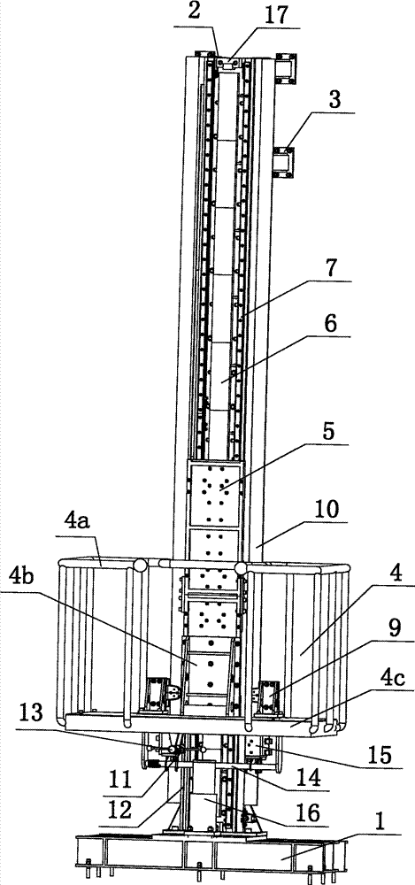
Fig. 3 is the front elevation of embodiments of the invention 1;
Fig. 4 is the lateral plan of embodiments of the invention 1;
Fig. 5 is the motion parts perspective view of embodiments of the invention 1;
Fig. 6 is the speed limiting mechanism perspective view of embodiments of the invention 1;
Fig. 7 is embodiments of the invention 2 perspective view;
Fig. 8 (A) is the birds-eye view of embodiments of the invention 2;
Fig. 8 (B) is the birds-eye view after embodiments of the invention 2 remove car;
Fig. 9 is the front elevation of embodiments of the invention 1;
Figure 10 is the lateral plan of embodiments of the invention 1;
Figure 11 (A) is the motion parts perspective view of embodiments of the invention 2;
Figure 11 (B) is the motion parts birds-eye view of embodiments of the invention 2;
Figure 12 (A) is mover 5 perspective view of embodiments of the invention 2;
Figure 12 (B) is mover 5 birds-eye vieies of embodiments of the invention 2;
In the accompanying drawing: 1. base, 2. support the girder steel assembly, support on 3., 4. car, the 4a. guardrail, 4b. strengthens gusset, 4c. car floor; 5. linear motor rotor, 5a. mover adapter plate, 5b. mover back iron, 5c. rotor permanent magnet, 6. linear motor stator electric, 7. line slideway; 8. slide block, 9. caliper brake, 10. braking rail, 11. gears, 12. tooth bars, 13. get rid of ball mechanism; 13a. get rid of ball mechanism connecting panel, 14. swing-bar mechanisms, 14a. rocker mechanism connecting panel, 15. safety tongss, 16. energy dispersers, 17. blocks; 18. the location wheels, 18a. location opinion wheel shelf, 18b. master's positioning and guiding wheel, 18c. side positioning and guiding wheel, 19. matrix strip slots, 20. torsion springs.
The specific embodiment
Following content is the detailed description that combines accompanying drawing that the present invention is done, and should not be understood that it is to qualification of the present invention.
The home lift embodiment 1 that directly drives of the present invention; Like Fig. 1, Fig. 2, Fig. 3, shown in Figure 4; Mainly comprise base 1, support girder steel assembly 2, on support 3, linear motor driver, car 4, locating guide device, brake equipment, safety tongs speed-limiting protection device, energy disperser 16.
Supporting girder steel assembly 2 is strip; Vertically be installed in the pit shaft; The bottom links to each other with the base that fixes on the ground 1, and top is fixed on the shaft in wall through last support 3, its positive linear motor stator electric 6 and line slideway 7 that linear motor driver is installed.Two sides supporting girder steel assembly 2 vertically respectively are provided with a braking rail 10, as the braking rail of drg 9 and safety tongs 15.Energy disperser 16 is installed in the top of base 1.The topmost that supports girder steel assembly 2 is provided with block 17, is used for spacingly, prevents overshoot.
For the linear electric motors of well known, General Definition: there have a side of armature loop to be called linear electric motors to be elementary, and there have a side of magnet to be called linear electric motors to be secondary, and also definition: motion parts is a linear motor rotor, and fixed part is a linear motor stator electric.The principle of work of linear electric motors is: feed electric current in the linear electric motors primary winding, produce a travelling-magnetic-field of magnet movement relatively, this travelling-magnetic-field and secondary magnet are synchronized with the movement, and then the drive linear motor rotor is done straight-line motion.
Linear motor driver of the present invention slide block 8 moving 5 by linear motor stator electric 6, linear electric motors, that be installed on the linear motor rotor is formed.Linear motor stator electric 6 lays fixing along the front of whole support girder steel assembly 2; Linear motor rotor 5 and linear motor stator electric 6 surfaces are parallel and keep a fixing air gap, and making can contactless relative motion between linear motor rotor 5 and the linear motor stator electric 6.The locating guide device of linear motor rotor 5 is accomplished by slide block 8 and line slideway 7, and slide block 8 moves along line slideway 7, guarantees the motion air gap between linear motor rotor 5 and the linear motor stator electric 6.
The home lift that directly drives of the present invention, described linear motor driver adopts the arrangement of linear electric motors collateral motion, primary fixed, perhaps adopts the arrangement of the elementary motion of linear electric motors, secondary fixed.
The motion parts that directly drives home lift of the present invention mainly is made up of car 4, mover 5, caliper brake 9.The motion parts schematic perspective view is as shown in Figure 5.Car 4 is made up of guardrail 4a, reinforcement gusset 4b, car floor 4c.Mover 5 is made up of mover adapter plate 5a, mover back iron 5b, rotor permanent magnet 5c, slide block 8; Rotor permanent magnet 5c sticks on mover back iron 5b, and upward the formation linear electric motors are secondary; Be fixed on then on the mover adapter plate 5a, slide block 8 is arranged at four jiaos of mover adapter plate 5a.Mover adapter plate 5a links to each other with car floor 4c, and reinforces through strengthening gusset 4b.Caliper brake 9 is fixed on the car floor 4c, acts on braking rail 10.
The home lift that directly drives of the present invention is provided with safety tongs speed-limiting protection device, and is by gear 11, tooth bar 12, get rid of ball mechanism 13, swing-bar mechanism 14, torsion spring 20, safety tongs 15 and form, as shown in Figure 6.Tooth bar 12 vertically is arranged in a side supporting girder steel assembly 2; Get rid of ball mechanism 13 and 11 coaxial connections of gear; And be connected with swing-bar mechanism 14, get rid of ball mechanism 13 and be connected with the bottom of the car floor 4c of car 4 with swing rod structure connecting panel 14a through getting rid of the connecting panel 13a of ball mechanism respectively with swing rod structure 14.Torsion spring 20 is installed on the swing-bar mechanism 14, through pretension qualification speed is set, and qualification speed is generally 115% of command speed.When car movement, with the speed operation, gear 11 drives the coaxial ball mechanism 13 of getting rid of and rotates gear 11 along tooth bar 12 and car 4, and the centnifugal force that gets rid of ball mechanism 13 raises along with the increase of cage operation speed.When speed reaches or surpass qualification speed; Get rid of the predetermincd tension of the centnifugal force conversion back of ball mechanism 13, then get rid of ball mechanism 13 and overcome the predetermincd tension of torsion spring 20, make safety tongs 15 actions through swing-bar mechanism 14 greater than torsion spring 20; Safety tongs 15 acts on the braking rail 10, and car 4 is stuck on the guide rail.
The home lift that directly drives of the present invention provides the linear electric motors of wireless gig, the power supply of car 4 through supply cable, power rail contact or the power rail no touch mode that is fixed on the vertical shaft in wall.
Fig. 7, Fig. 8, Fig. 9, Figure 10 are the scheme drawing that directly drives home lift embodiment 2 of the present invention, and it is the distortion on embodiment 1 basis, and the locating guide device of linear motor rotor adopts the location wheels to realize.
Figure 11 and shown in Figure 12 is respectively the said scheme drawing that directly drives home lift motion parts and mover 5.Location wheels 18 are made up of locating wheel shelf 18a, main positioning and guiding wheel 18b, side positioning and guiding wheel 18c, and wheel carrier 18a links to each other with mover adapter plate 5a through the location, is arranged at four jiaos of mover adapter plate 5a.
Support the front of girder steel assembly 2, the both sides of linear motor stator electric 6 vertically are provided with two matrix strip slots 19, and opening is outside.Two madial walls of matrix strip slot 19 contact with the wheel face of the main positioning and guiding wheel 18b of guide-localization wheels 18; The external diameter of main positioning and guiding wheel 18b is suitable with the A/F of matrix strip slot 19, keep main positioning and guiding wheel 18b in matrix strip slot 19 about vertical motion; The lateral register track adjusting wheel 18c of guide-localization wheels 18 is along spill strip slot 19 1 side end faces vertical motion up and down.
The said linear motor driver that directly drives in the home lift can be divided into two into two linear electric motors; Two braking rail unite two into one, and braking rail 9 is arranged between these two linear motor stator electrics, and braking rail only is provided with one; Braking rail is a T shape; The braking rail bottom surface vertically is arranged on the front of support girder steel assembly 2, and drg and safety tongs are separately fixed at car floor or mover top or mover top and the bottom, can respectively be provided with 1 pair or 2 pairs.All the other are with embodiment 1 or embodiment 2.
The foregoing description only is explanation technical conceive of the present invention and characteristics, and its purpose is to let the personage who is familiar with this technology can understand content of the present invention and enforcement according to this, can not limit protection scope of the present invention with this.All equivalences that spirit is done according to the present invention change or modify, and all should be encompassed within protection scope of the present invention.