A kind of two-stage plasma gasification fusion cleavage method and device thereof that contains organic discarded object
Technical field
The present invention relates to a kind of contain organic discarded object processing method, be specifically related to a kind of two-stage plasma gasification fusion cleavage method and device thereof that contains organic discarded object, belong to gasification and melting cracking technique field.
Background technology
Decomposing process and the organic matter rubbish thermal decomposer of people CN 1935399A organic matter rubbish such as Chinese invention patent Taketa Shigeshi, introduced and released electric material and discharge electronics at a certain temperature and do irregular movement, around under the permanent-magnetic field effect of She Zhiing, screw is accelerated in excitation, follow mutual bump, the bombardment organic substance produces cation and electronics, brings out the corona plasma reaction, extremely unstable electric field occurs.And new cation and the electronics that produces, the corona plasma reaction is brought out in multiplication randomly again, makes to close on organic cation and the electronics of producing, thereby produces chain type corona heat plasma precursor reactant.And then organic matter gasification is decomposed into steam, has the gas of anion and has the ashes of anion on a small quantity.Through the air magnetizer, have the air of anion, enter the corona plasma conversion zone, under the common excitation of the original magnetic field that is subjected to disturbance and unstable electric field, produce turbulent flow, promote chain type corona plasma reflection diffusion to come, accelerate organic gasification, obtained effect preferably.But one of problem that occurs is, is not easy to handle contain a large amount of inanimate matters especially pottery and metal waste, particularly danger wastes can not be handled; Two of problem is because reaction temperature generally at 150~650 ℃, can inevitably produce tar with bioxin; Three of problem is to use the gas magnetizing device of having leisure, and does not change the component of air, and a large amount of nitrogen are brought into, only can increase the weight of the burden of follow-up exhaust treatment system; Four air magnetizer magnetic of problem a little less than, make a little less than the air ionization that pyrolysis rate organic in the reactor is slow; Five of problem is that the high energy product permanent magnet does not arrange cooling system, and obviously permanent magnet can demagnetize because the Curie-point temperature effect is under the higher temperature for a long time, directly can cause the decline of magnetic controlled plasma effect; Six of problem, the essential extra process of the lime-ash that produces, particularly enrichment toxicity lime-ash more needs specially treated.
The WO 2009/084631 of international monopoly Yamamoto positive, the spy that people's such as the blue or green wooden large will of Japan Patent spy opens people such as the military history of 2010-58103 and riverhead opens 2008-175511, the CN201069309Y of Chinese patent Hirakui Kenzo and people's such as Harada Yoshikazu CN2860646Y basic principle is similar to people CN 1935399A such as Chinese invention patent Taketa Shigeshi, just have any different on the structure of reactor, still all there are above-mentioned six big problems, even improve through on the structure, can handle the discarded object that some have small number inorganic substances component, but obtain contain metal, mixed ash such as pottery still need subsequent technique to handle especially.
Island and also wait people's spy to open and introduced a kind of magnetic fluid and magnetic cell processor among the 2007-105703 in the Japan Patent, mainly utilized the high field intensity magnetic field of the high energy product permanent magnet assembly inner passage formation of HALBACH array, the fluid of this passage of flowing through is magnetized, obtain containing the active fluid of ion characteristic.Such as, this fluid is air, then can obtain and the active high air of other substance reaction, but constituent of air does not change.If be applied to the pyrolysis aspect of organic substance, nearly 3/4 the nitrogen that then occupies air does not almost play effective function, bring unnecessary burden can on the contrary follow-up vent gas treatment.
What pay attention among my Chinese patent CN 101088581, CN 101648200 and the CN 201496973U is that the fusion cracking of plasma arcs district is gone in the direct stepping of discarded object, though can a step reclaim metal, vitreum and synthesis gas, but power consumption is higher, and the flying dust amount is bigger, if follow-up fuel gas generation, the electric power that may send can not be self-sufficient.
Summary of the invention
The objective of the invention is for overcoming above-mentioned the deficiencies in the prior art part, a kind of two-stage plasma gasification fusion cleavage method and device thereof that contains organic discarded object is provided, it is big to handle the energy consumption that contains organic waste matter with solution plasma arcs fusion cracking, the wretched insufficiency that flying dust is many, thereby thoroughly reach maximized organic matter mass-energy and the treatment effeciency of utilizing, thorough pyrolysis fuel oil, reduce the generation probability of bioxin, as much as possiblely obtain high-quality high heating value synthesis gas, be follow-up gasifying electricity generation, Hydrogen Energy reclaims or the production of green liquid fuel provides safeguard, finish a step simultaneously and reclaim precious metal and the vitreum that can directly utilize building materials field, lay the first stone for containing the large-scale commercial development of organic discarded object mass-energy and application, solve simultaneously thoroughly the particularly emission problem of possible pollutant in the danger wastes gasification of organic matter gasification.
The present invention realizes with following technical scheme: a kind of two-stage plasma gasification fusion cleavage method and device thereof that contains organic discarded object, it is characterized in that: described method comprises that magnetic controlled plasma gasifies, pulse is strengthened the whirlwind effect and independently caught flying dust vitrifying and plasma arcs fusion cracking, generates synthesis gas, reclaims precious metal and vitreum; The gasification of described magnetic controlled plasma be the inner space at three layers of furnace shell of magnetic controlled plasma vaporizer arrange pyroelectricity mineral material such as tourmaline and or material such as amethyst and water-cooled high energy product permanent magnet set up original magnetic field, feed the oxygen-enriched air that contains the low-density plasma simultaneously, pyroelectricity mineral material emission electronics, bombardment is organic, bring out and or multiplication bring out the reaction of chain type corona plasma; The reaction of chain type corona plasma is strengthened in the oxygen-enriched air input that contains the low-density plasma, interval 150 ℃~950 ℃ of gasification temperature; Described pulse is strengthened the whirlwind effect and is independently caught interval 950 ℃~1250 ℃ of flying dust vitrifying regional temperature; Interval 1250 ℃~1550 ℃ of described plasma arcs fusion cracking temperature, material evenly enters in the magnetic controlled plasma vaporizer by controlled fabric type feed bin, the gasification gas that gasification obtains and residue pass multifunctional pulse and strengthen the whirlwind effect compartment, catch the flying dust vitrifying, enter plasma arcs fusion cracking room at last, the melten glass body and the liquid metal that obtain excrete by passage, the synthesis gas that obtains passes passage and enters the synthesis gas water cooler, enter the quill shaft that to vert, and then under air-proof condition, introduce synthetic gas cleaning system and recycle.
The described oxygen-enriched air that contains the low-density plasma is to be produced by the oxygen-enriched air generator that contains the low-density plasma, described oxygen-enriched air generator be by the magnetic field processor and or multistage magnetic field processor be in series, each magnetic field processor is again by 4 magnetic field processing unit M
1, M
2, M
3, M
4Form according to the spiral layout serial connection in magnetic field, have the diamagnetism division board to isolate mutually again between each magnetic field processing unit: each magnetic field processing unit is arranged according to the HALBACH mode by the high energy product permanent magnet of 8 two kinds of dimensions, and the chevron magnetic pole head that arranges in the internal gas passage has N
2Overflow channel has N on the diamagnetism chevron structure
2Overflow channel has a N on the high energy product permanent magnet
2The overflow channel hole, the N of the diamagnetic material square tube of outside
2Overflow channel, the corresponding perforation.
Described magnetic controlled plasma vaporizer arranges the pyroelectricity mineral material and vertical bar shape water-cooled high energy product permanent magnet is set up original magnetic field at the inner space of furnace shell, described internal layer furnace bladder material adopts magnetism-free stainless steel, it is provided with perpendicular strip grid shape hole, grid shape hole length 10CM-30CM, grid shape hole width 0.1CM-1CM, per two grid shape pitch of holes 1CM-10CM; Water-cooled high energy product permanent magnet is extremely alternate and establish by S, N, and adjacent S, the N utmost point are at a distance of 20-40CM; A through hole is set between adjacent S, the N utmost point, and is connected with the oxygen-enriched air generator that contains the low-density plasma of furnace shell outside.
Described multifunctional pulse is strengthened the whirlwind effect compartment and is provided with rotatable gear wheel in the portion top within it, and rotatable gear wheel is attached with fire grate; Be provided with a plurality of Venturi nozzles in the exterior airbag, it is layer hollow steam generator that whirlwind effect compartment shell is strengthened in the function pulse, also be provided with left hollow rotating shaft, right hollow rotating shaft on the multifunctional pulse reinforcement whirlwind effect compartment shell, form the synthesis gas passing away.
At least 1 direct-current plasma arc generator and dragging system thereof are set on the shell of described plasma arcs fusion cracking room, the synthesis gas of the described plasma arcs fusion cracking room passage of coming out of the stove is strengthened the right hollow rotating shaft that arranges on the whirlwind effect compartment by come out of the stove synthesis gas water cooler and multifunctional pulse and is sealed and dock, and the synthesis gas that plasma arcs fusion cracking room is produced is externally exported reliably; Metal bath and or the melten glass body excrete smoothly through passage; The flying dust that follow-up purified synthesis gas obtains can return and carry out plasma arcs fusion cracking again, reclaims vitreum.
Described magnetic controlled plasma room area is subjected to bottom plasma arcs fusion cracking heat radiation, for contain organic less danger wastes such as incineration of refuse flyash and or the purified synthesis gas flying dust, granulate through making ball, enter 100 ℃~500 ℃ of the indoor preheatings of magnetic controlled plasma, regulation and control are handled through the revolving burner grate, enter plasma arcs fusion cracking zone vitrifying and metal melting thereof.
Advantage of the present invention is: (1) two-stage plasma gasification fusion cracking, make that containing waste of organic matter, carbonaceous material etc. is thoroughly gasified, energy consumption minimized, the maximization of synthesis gas production capacity, reclaim vitreum and the precious metal that can supply building materials field directly to utilize simultaneously, make the best use of everything, thoroughly non-pollutant discharge and transfer, can satisfy the environmental protection standard of any strictness, be the Environmentally-sound technology of a non-burning.
(2) magnetic controlled plasma gasification reflection operation design continuously, the particularly feeding of low-density plasma oxygen-enriched air makes gasification reaction reach high efficiency.
(3) descending being rapidly heated of gasification gas continue to be decomposed, and the design of whirlwind effect is strengthened in pulsation, makes flying dust class in the flue gas stay and finishes vitrifying in the stove, does not finish gasification substance, intermediate product comprises that tar class material continues to decompose.
(4) all above-mentioned two steps are handled not material completely, thoroughly are cracked into the micro-molecular gas to the environment friendliness, melten glassization, and Metal Melting is melted, and carbon residue thoroughly gasifies, and can both be satisfactorily resolved in high-temperature plasma arc fusion cracking zone, bottom; And then make the synthesis gas energy maximization that obtains, improve organic gasification efficiency substantially.It needs to be noted the HCl, the SO that are obtained by the raw material cracking in the synthesis gas at this
2Deng the sour gas molecule, can in follow-up purified synthesis gas, be converted into salt by alkaline neutralisation treatment very easily and reclaim; The flying dust that follow-up purification synthesis gas produces can return the cracking of plasma arcs second melting, thereby thoroughly reaches zero release of pollutant.
(5) the entire reaction device need not to add auxiliary fuel, can realize that quick startup stops fast; Scale is changeable, does not influence efficient.
(6) resource utilization degree height, effluent all are valuable products.
(7) project implementation cycle weak point makes things convenient for addressing, is easy to large-scale commercialization and popularizes.
(8) application is wide, but extensive treatments: living beings, carbonaceous material comprise energy substance, contain organic discarded object and danger wastes etc., big to relative humidity, material source complexity or all kinds of high-risk such as medical waste and the difficult discarded object that decomposes can efficiently be handled equally as containing the discarded object of 12 kinds of persistence organic pollutants (POPs).
Description of drawings
Fig. 1 is two-stage plasma gasification fusion cracker structural representation;
Fig. 2 and Fig. 3 are that controlled fabric type feed bin is faced and the plan structure schematic diagram;
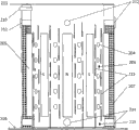
Fig. 4 and Fig. 5 are magnetic controlled plasma vaporizer cross section and vertical section structure schematic diagram;
Fig. 6 contains low-density plasma oxygen-enriched air generator magnetic field processing unit cross-sectional structure schematic diagram:
Fig. 7 contains low-density plasma oxygen-enriched air generator magnetic field processor structure schematic diagram;
Fig. 8 is 4 magnetic field processing unit M that contain low-density plasma oxygen-enriched air generator magnetic field processor
1, M
2, M
3, M
4Spiral magnetic field arrange schematic diagram;
Fig. 9 contains the multistage magnetic field of low-density plasma oxygen-enriched air generator processor series connection schematic diagram;
Figure 10 and Figure 11 multifunctional pulse are strengthened the whirlwind effect compartment and are faced the plan structure schematic diagram;
Figure 12 and Figure 13 plasma arcs fusion cracking room are faced and the plan structure schematic diagram;
Among Fig. 1,1, controlled fabric type feed bin, 2, the magnetic controlled plasma vaporizer, 3, multifunctional pulse is strengthened the whirlwind effect compartment, 4-1 and 4-2 are respectively the single unit system left and right sides quill shaft bearings that can vert, 5, plasma arcs fusion cracking room, and 6-1 and 6-2 are respectively the single unit system pillars.
Among Fig. 2 and Fig. 3,101, air-introduced machine, 102, distribute roll, 10201, star arrangement combination material toggling tooth, 10202, the universal joint shaft coupling, 10203, frequency conversion reductor and drive motors thereof.
Among Fig. 4 and Fig. 5,201, hollow shell, 202, inner bag, 203, contain low-density plasma oxygen-enriched air generator, 204, low-density plasma oxygen-enriched air air inlet pipe, 205, water-cooled permanent magnet, 206, thermocouple, 207, release electric mineral material, 208, magnetic controlled plasma gasification gasification zone, 209, magnetic controlled plasma vaporizer base flange, 210, gasifying agent supply mouth, 211, magnetic controlled plasma vaporizer top flange, 212, Mi Feng Shi lookout window, 213, grid shape hole, 214, sealed manhole, 215, thermocouple.
Among Fig. 6,7,8,9,20301, the atresia permanent magnet, 20302, porose (N
2Overflow channel) permanent magnet, 203021, N
2Overflow channel, 20303, diamagnetic porose (N
2Overfolw hole) square tube, 203031, N
2Overfolw hole, 20304, diamagnetic square tube, 20305, porose (N
2Overflow channel) chevron magnetic pole head, 203051, N
2Overflow channel, 20306, porose (N
2Overflow channel) diamagnetism chevron structure, 203061N
2Overflow channel, 20307, the diamagnetism air inlet pipe, 20308, porose (N
2Overflow channel) diamagnetism shutoff plate, 203081, N
2Overflow channel, 20309, the diamagnetism division board, 20310, air valve, 20311, the diamagnetism bridge piece, 20312, the diamagnetism escape pipe.
Among Figure 10 and Figure 11,301, hollow water-cooled cross gear support, 302, gear bearing wheel (totally 4), 303, gear wheel, 304, the gear centre alignment pin, 305, pinion, 306, the steam outlet pipe, 307, double-deck hollow steam generator, 308, air bag, 309, pulse electric Venturi nozzle (4 cover), 310, the quill shaft flange, 311, right quill shaft (synthesis gas passage), 312, the vertical synthesis gas passage of water-cooled, 313, flange, 314, liquid level gauge, 315, thermocouple, 316, left side quill shaft, 317, pinion drives reducing motor, 318, gasification gas reformation gas entrance, 319, cold water is mended entrance, 320, fire grate, 321, the hot water outlet.
Among Figure 12 and Figure 13,501, direct-current plasma arc generator, 50101, direct-current plasma arc generator dragging system, 502, the synthesis gas water cooler of coming out of the stove, 50201, synthesis gas water cooler seal cover, 50202, synthesis gas water cooler delivery port, 50203, synthesis gas water cooler water inlet, 503, furnace bottom potential test extraction pole, 504, manhole, 50401, the manhole seal cover, 505, the synthesis gas passage of coming out of the stove, 506, the peephole passage, 50601, the peephole seal cover, 507, the high temperature camera system, 508, the mouth of a river/cinder notch passage, 509, water/slag is chewed, 510, synthesis gas water cooler abutted flange, 511, refractory material, 512, the molten bath, 513, temperature thermocouple, 514, temperature thermocouple.
The specific embodiment
Below in conjunction with accompanying drawing the present invention is described in further detail:
As shown in Figure 1, this contrive equipment comprises that 4 main unit have controlled fabric type feed bin 1, magnetic controlled plasma vaporizer 2, the multifunctional pulse at top to strengthen whirlwind effect compartment 3, plasma arcs fusion cracking room 5, with 1 auxiliary unit supporting construction that is single unit system, it comprises again and can reliably connect by flange seal between 4 main unit for single unit system can vert bearing 4-1 and 4-2, single unit system pillar 6-1 and the 6-2 of left and right sides quill shaft.
Fig. 2, Fig. 3 are respectively facing of controlled fabric type feed bin 1 and plan structure schematic diagram thereof.Side, top at controlled fabric type feed bin 1,1 air-introduced machine 101 is set, its function is that the waste gas and the dust that occur during with controlled fabric type feed bin 1 charging and blanking suck air-introduced machine 101, and it is sent in the magnetic controlled plasma vaporizer 2, pile up organic discarded object that contains to be processed in the middle and upper part of controlled fabric type feed bin 1, bottom at controlled fabric type feed bin 1, be provided with the distribute roll 102 of controlled speed, it is provided with star arrangement combination material toggling tooth 10201, be used for the packing of packed discarded object is colluded the thorn broken bag, have concurrently simultaneously to tear up and loose function and finish uniform distribution.Because distribute roll 102 is according to the difference of material, require it to have certain yielding and visit stuck function, therefore 102 liang of proper supporting bearing base of distribute roll can be able to be designed to make a concession structure, in order to satisfy its relative flexibility running, between distribute roll 102 and frequency conversion reductor and drive motors system 10203 thereof, universal joint shaft coupling 10202 is set especially.
Fig. 4 and Fig. 5 are magnetic controlled plasma vaporizer 2 cross sections and vertical section structure schematic diagram.Hollow shell 201 and three layers of furnace shell of inner bag 202 common compositions, between hollow shell 201 and inner bag 202, be filled with and release electric mineral material 207, inner bag 202 arranges grid shape hole 213 releasing the following position of electric mineral material 207 packed heights, is convenient to release the electronics that electric mineral material 207 overflows and enters magnetic controlled plasma gasification gasification zone 208.The water-cooled permanent magnet 205 of high energy product is set between hollow shell 201 and inner bag 202, and water-cooled permanent magnet 205 is at the inboard N of inner bag 202, S is extremely alternate and establish, N, S die opening 20~40CM, thereby make the ion that enters field region, electronics is under Lorentz force action, formula motion in the shape of a spiral, be convenient to repeatedly bombard organic matter, organic at ion, under the bombardment of electronics, just producing, anion and electronics, simultaneously these are being just, anion and electronics, under the control of magnetic field, continue again under Lorentz force action, formula motion in the shape of a spiral, bombardment is organic again, just producing again, anion and electronics form multiplication and bring out the corona plasma reaction.Magnetic controlled plasma vaporizer 2, strengthen whirlwind effect compartment 3 with multifunctional pulse respectively by magnetic controlled plasma vaporizer base flange 209, magnetic controlled plasma vaporizer top flange 211 usefulness bolts and be connected with controlled fabric type feed bin 1, the junction guarantees good sealing effectiveness.Upper side at magnetic controlled plasma vaporizer 2 arranges gasifying agent supply mouth 210, adds gasifying agent as required, and gasifying agent can make oxygen, water vapour and or air etc.Middle part and bottom at magnetic controlled plasma vaporizer 2 arrange thermocouple 206 and 215 respectively, so that the diverse location to magnetic controlled plasma gasification zone carries out temperature detection monitoring, and then addition and or adding height and the charging rate of discarded object that can regulate gasifying agent.Be provided with close envelope formula lookout window 212, sealed manhole 214 respectively in the upper and lower part of magnetic controlled plasma vaporizer 2, all played important function for plant maintenance and the observation of waste gasification situation.
In the magnetic controlled plasma gasification zone, gasification temperature can be controlled from top to bottom in ℃ scope of room temperature~950.
Be connected with and contain low-density plasma oxygen-enriched air generator 203 being formed three layers of furnace shell jointly by hollow shell 201 and inner bag 202, this generator can be shown in Fig. 6 as required, it also can be the processor of multistage magnetic field shown in Fig. 9, each magnetic field processor is arranged and is formed according to Fig. 7, the spiral shape magnetic field of advancing shown in Figure 8 by 4 magnetic field processing unit M1, M2, M3, M4 again.Fig. 6 contains low-density plasma oxygen-enriched air generator magnetic field processing unit cross-sectional structure schematic diagram, Fig. 7 contains low-density plasma oxygen-enriched air generator magnetic field processor structure schematic diagram, and Fig. 8 contains 4 magnetic field processing unit M of low-density plasma oxygen-enriched air generator magnetic field processor
1, M
2, M
3, M
4Spiral magnetic field arrange schematic diagram, Fig. 9 contains the multistage magnetic field of low-density plasma oxygen-enriched air generator processor series connection schematic diagram.As shown in Figure 7, each magnetic field processing unit magnetic pole is formed by two kinds of high energy product permanent magnet combinations, is respectively atresia permanent magnet 20301, porose (N
2Overflow channel) permanent magnet 20302, and atresia permanent magnet 20301 is distributed in 4 bights of magnetic field processing unit, porose (N
2Overflow channel) permanent magnet 20302 is distributed in the middle part on foursquare 4 limits, but these porose (N
2Overflow channel) magnetizing direction of permanent magnet 20302 is relevant with residing position, and the magnetizing direction of the atresia permanent magnet 20301 in same 4 bights and layout thereof are not careless yet, and 8 permanent magnets combinations are arranged according to the HALBACH mode.Magnetic field reaches the strongest in the magnetic field units processor inner passage in order to make, and generally makes the internal air passageway magnetic field intensity increase to 1.5~3 times than conventional spread mode magnetic field intensity, and porose (N is set in this passage
2Overflow channel) chevron magnetic pole head 20305 and porose (N
2Overflow channel) diamagnetism chevron structure 20306 has increased this regional magnetic field gradient value more, gradient magnetic effect herein, and paramagnetism oxygen is gathered among the passage, and diamagnetism nitrogen is then by being arranged on N on the permanent magnet
2The aperture N that overflow channel 203021 and magnetic pole head run through
2 Overflow channel 203051 and porose (N
2Overflow channel) aperture N on the diamagnetism chevron structure 20306
2 Overflow channel 203061 overflows smoothly, thereby finishes the gathering of oxygen; The nitrogen that overflows compiles by porose (N
2Overflow channel) N of diamagnetism shutoff plate 20308
2 Overflow channel 203081 overflows the magnetic field processor.4 magnetic field processing units present cyclone mode according to inner air and are combined as the magnetic field processor, adopt diamagnetism division board 20309 to isolate between each magnetic field processing unit, avoid the phase mutual interference in each magnetic field, unit as far as possible.The diamagnetic square tube 20304 of the employing shell of magnetic field processor, inner casing adopts diamagnetic porose (N
2Overfolw hole) square tube 20303, and 203031N is arranged on it
2Overfolw hole, these designs all are the structural assurances that efflux smoothly for nitrogen.In order to obtain treatment effect preferably, we can also interconnect a plurality of magnetic fields processor with diamagnetism escape pipe 20312 and diamagnetism bridge piece 20311, form multistage magnetic field processor.Multistage magnetic field processor diamagnetism air inlet pipe 20307 is connected with air valve 20310, can effectively control the inlet of air.
Because the diamagnetism of gases such as oxygen paramagnetism and nitrogen in gradient magnetic, is assembled oxygen, repel nitrogen, and magnetic field is more strong, magnetic field gradient is more big, more is conducive to the gathering of oxygen, and scientific and technological circle have become common recognition, no longer repeat to introduce its mechanism at this.But in magnetic field, can make oxygen obtain activation, produce the low-density plasma, also rarely known by the people.With the high energy product permanent magnet according to HALBACH arrayed squarely pipeline section shape magnetic field processing unit M1, M2, M3, M4, make the internal air passageway magnetic field intensity increase to 1.5~3 times than conventional spread mode magnetic field intensity, chevron magnetic pole head is set in this passage, has increased this regional magnetic field gradient value more; 4 magnetic field processing units present cyclone mode according to inner air and are combined as the magnetic field processor, adopt diamagnetism division board 20309 to isolate between each magnetic field processing unit, avoid the phase mutual interference in each magnetic field, unit as far as possible.In order to obtain treatment effect preferably, we can also form multistage magnetic field processor with the series connection of a plurality of magnetic fields processor.
Because the elementary particle of constitute---electron spin (reporting certainly) motion, cause spinning electron to produce electromagnetism ether spiral and form magnetic dipole and magnetic moment, therefore the atom of all chemical elements enters in the magnetic field of certain intensity, when the direction of electron spin magnetic pole and external magnetic field is opposite, when the magneticaction effect meets or exceeds the ionization energy of this element, electronics just can be shaken off nuclear attraction becomes photoelectron, namely produces the quantum transition phenomenon.Electronics is stimulated and makes the ground state of atom enter excitation state, has realized from magnetic energy to the ionization transformation of energy, and obviously, the ionisation effect of magnetic and the penetration of magnetic have close contacting.
The computing formula of magnetic field magnetic energy is
Wherein W represents magnetic field magnetic energy, and H, B are respectively magnetic field intensity and magnetic induction intensity, and integration spreads all over the space that magnetic field exists, and this shows and the space that magnetic field exists can be divided into countless volume elements that namely the magnetic energy of each volume element is
Total magnetic energy then is their summation (integration).Magnetic field energy density
Because the high energy product NdFeB material, along with the content increase of neodymium metal, magnetic energy product is from 260kJ/M
3Can increase to 500kJ/M
3More than, add the particularity of HALBACH array, the magnetic field energy density in the magnetic field processing unit passage here can be up to 650kJ/M
3More than.Again because first ionization energy of oxygen element and nitrogen element is respectively 13.618eV and 14.53eV, first ionization energy that conversion can get oxygen element and nitrogen element is respectively 1313.95kJ/mol and 1401.95kJ/mol, as not considering other factors, first ionization energy of oxygen element and nitrogen element can be scaled 58685.5kJ/NM respectively again
3And 62486.4kJ/NM
3Obviously can provide enough magnetic energy for oxygen in the air and nitrogen ionization in this magnetic field processing unit passage, that is to say, air that can ionization about 1% in this magnetic field processing unit passage, wherein the oxygen ionizing power is 1.07 times of nitrogen ionizing power.If the consideration multistep treatment increases at the numerical quantity that contains step by step that adds oxygen, low-density plasma and active oxygen have appearred in the oxygen-enriched air after the fraction ionization.
Assurance as the basic heat of gasification reaction, the oxygen-enriched air generator that contains the low-density plasma by original creation, for the reaction of chain type corona plasma provides the oxygen-enriched air that contains the low-density plasma, negative ions in the low-density plasma in the oxygen-enriched air, free electron are after entering magnetic field, under the Lorentz force effect, make screw movement, bombardment is organic, has strengthened existing corona plasma reaction; Active oxygen in the oxygen-enriched air of low-density plasma, as singlet oxygen (singlet oxygen), it is that ground state oxygen has been accepted magnetic energy and is transformed into.Singlet oxygen has two kinds:
1Δ gO
2State exceeds 93.7kJ (22.4kcal) than the energy of ground state oxygen; 1 ∑ g
+State then more active energy than ground state oxygen exceeds 156.9kJ (37.5kcal), thereby more makes the plasma gasification process accelerate speed.
Generally speaking, this magnetic field processor can enrichment increase nearly 1~3 percentage point of oxygen, and 1 percentage point of oxygen of every increase in the air is reacted in participation in the combustion reaction, just can increase about 50 ℃ of reaction temperature, so according to the required control temperature of gasification reaction, select the series connection progression of magnetic field processor, this just arranges the main cause of multistage magnetic field processor herein as required.
Figure 10 and Figure 11 are that multifunctional pulse reinforcement whirlwind effect compartment 3 is faced the plan structure schematic diagram.Why be referred to as multi-functional, be because here as " furnace bosh ", it not only plays the effect of forming a connecting link to magnetic controlled plasma vaporizer 2 and the bottom plasma arcs fusion cracking room 5 on top, and also finished other 3 functions in this zone, specify as follows:
The double-deck hollow steam generator 307 of shell of strengthening whirlwind effect compartment 3 at multifunctional pulse is provided with the hollow water-cooled cross gear support 301 that connects with it, on this hollow water-cooled cross gear support 301, by being set, 4 gear bearing wheels 302 supporting rotatable gear wheel 303, drive at pinion under the driving of reducing motor 317 and pinion 305, gear wheel 302 is rotated.The spoke of gear wheel 302 is provided with and has fire grate 320.On gear centre alignment pin 304, as required, the setting gauge that rotates synchronously with gear wheel 302 can be set, lump in gasification to prevent the top discarded object.The gasification gas that magnetic controlled plasma vaporizer 2 produces is descending under the negative pressure traction in bottom plasma arcs fusion cracking room 5, inorganic matters such as ashes and other metal are by fire grate 320, fall into bottom plasma arcs fusion cracking room 5, thoroughly be not gasificated into the residual thing of micromolecular organic matter and middle long-chain tar, carbon residue also enters plasma arcs fusion cracking room 5 thereupon, this is the important fire grate buffer action of forming a connecting link that plays as " furnace bosh ".
On the air bag 308 that arranges on the double-deck hollow steam generator 307, be furnished with pulse electric Venturi nozzle (4 cover) 309, pulse gas can adopt nitrogen, steam and or air, under the pulse gas effect, make multifunctional pulse strengthen and present pulse reinforcement whirlwind effect in the whirlwind effect compartment 3, the a large amount of dust that make gasification gas carry are stranded on the refractory material furnace wall, increased the stop path of gasification gas in device simultaneously, reach certain thickness or fusing, softening point, flow down along the furnace wall and enter plasma arcs fusion cracking room 5 molten baths 512.This is referred to as pulse strengthens the whirlwind effect and finishes that the interception flying dust mainly acts in the stove, prolongs the residing time in furnace of gasification gas simultaneously.
The gasification gas that top magnetic controlled plasma vaporizer produces often needs to reform, the generation of using overheated steam as reforming is just 307 li of double-deck hollow steam generators, so necessary liquid level gauge 314, steam outlet pipe 306, cold water benefit entrance 319 are set on it, adjust gas production hot water outlet 321, gasification is reformed and is used steam entry 318.
Because this device is come out of the stove smooth and easy in order to make metal bath and vitreum in plasma arcs fusion cracking room 5 molten baths 512, whole device arranges rotating mechanism, rotating shaft just is arranged on multifunctional pulse to be strengthened on the double-deck hollow steam generator 307 of shell of whirlwind effect compartment 3, for synthesis gas is docked with synthetic gas cleaning system smoothly, again because docking location is static relatively, syngas outlet is arranged in the hollow rotating shaft, and the end of left and right sides quill shaft is equipped with quill shaft flange 310.In the quill shaft 316 of a left side thermocouple 315 is set, be used for measuring multifunctional pulse and strengthen temperature in the whirlwind effect compartment 3, as the vertical synthesis gas passage 312 of water-cooled being set again near the right quill shaft 311 of synthesis gas passage and connecting with it, and the synthesis gas water cooler 502 of coming out of the stove that arranges on the vertical synthesis gas passage of water-cooled 312 belows and the plasma arcs fusion cracking room 5 is realized sealing and is docked.
Figure 12 and Figure 13 are that plasma arcs fusion cracking room 5 is faced and the plan structure schematic diagram, and be indoor at this, the metal remelting, and other inorganic matter vitrifyings, organic matter tar etc. thoroughly was cracked into micro-molecular gas CO, the H to the environment friendliness in the middle of remaining organic matter comprised
2, HCl etc., carbon residue under the effect of water vapor plasma arc, finish thorough conversion and or coal gasification reaction, obtain callable precious metal, can be directly used in the vitreum of building materials field, rich hydrogen high energy synthesis gas, this also is one of basic point of the present invention.
Plasma arcs fusion cracking room 5 is provided with direct-current plasma arc generator 501 and dragging system 50101 thereof, 3000 ℃~10000 ℃ plasma arcs high-temperature region is provided for indoor reaction, ensure plasma arcs fusion cracking room 5 " burner hearth " temperature at 1250 ℃~1550 ℃, guarantee that the synthesis gas tapping temperature is 1250 ℃.Direct-current plasma arc generator 501 can use the graphite electrode of carrier gas such as center feeding water vapour with holes, also can use transferred arc or untransferable arc water-cooled metal plasma arcs torch, at least 1 of direct-current plasma arc generator 501 quantity, in order to regulate the distance in a plurality of direct-current plasma arc generators and molten bath, furnace bottom potential test extraction pole 503 is set in bottom refractory, is used for taking out electric potential signal.The synthesis gas passage 505 of coming out of the stove is arranged on refractory material 511 furnace walls, side, molten bath top, the synthesis gas water cooler 502 of coming out of the stove that is of sealing butt joint which is provided with synthesis gas water cooler seal cover 50201, synthesis gas water cooler delivery port 50202, synthesis gas water cooler water inlet 50203, synthesis gas water cooler abutted flange 510 with it.Be convenient to control when moving for equipment, on plasma arcs fusion cracking room 5, also be respectively arranged with peephole passage 506, peephole seal cover 50601, high temperature camera system 507.Vitreum and metal bath are chewed 509 by 508 mouths of a river/cinder notch passage and water/slag and are allowed the cast of coming out of the stove of slags gold cocurrent flows in the molten bath 512, finish natural layering in ingot mould, also cinder notch and the mouth of a river can be set respectively, pour into a mould respectively.Temperature thermocouple 513 can accurately feed back plasma arc chamber mean temperature, and temperature thermocouple 514 can accurately feed back the tapping temperature of synthesis gas.For the ease of maintenance, on plasma arcs fusion cracking room 5, also be provided with manhole 504, carry out positiver sealing by manhole seal cover 50401 on it.
Specify, because bottom plasma arcs heat radiation and conduction, material at the magnetic controlled plasma vaporizer on top can also be accepted preheating, therefore for contain organic less danger wastes such as incineration of refuse flyash and or the purified synthesis gas flying dust, granulate through making ball, can the access to plant preheating 100 ℃~500 ℃, through revolving burner grate regulation and control processing speed, enter plasma arcs fusion cracking zone vitrifying and metal melting thereof.
Embodiment 1,
Biohazard Waste, calorific value HHV (higher calorific value) 15MJ/kg, treating capacity 500kg/hr, composition (%wt): 50C, 7H, 25.7O, 1N, 0.5S, 0.8Cl, 15ASH (ash content), 35Moisture (humidity); Direct-current plasma arc power 100kW; Obtain the stripped about 75kg/hr of glass; Produce 1200 ℃ of synthesis gas, 1550NM
3/ hr, synthesis gas chemical heat butt HHV4.14MJ/NM
3, wet basis HHV3.39MJ/NM
3, sensible heat 2932MJ/hr; Synthesis gas mol ratio (%mol): 0.01CH
4, 0.00C
2H
2, 0.00C
2H
4, 13.76CO, 7.82CO
2, 15.17H
2, 0.12HCl, 18.19H
2O, 0.08H
2S, 44.87N
2Tail gas bioxin discharge capacity<0.1ng I-TEQ/NM after the purified synthesis gas utilization
3
Embodiment 2,
Rice husk, calorific value HHV (higher calorific value) 10.2MJ/kg, treating capacity, 1000kg/hr, composition (%wt): 32.4C, 4.6H, 38.5O, 0.6N, 0.2S, 23.7ASH, 15Moisture; Direct-current plasma arc power 200kW; Obtain the about 240kg/hr of vitreum; Produce 1200 ℃ of synthesis gas, 2211NM
3/ hr, synthesis gas chemical heat butt HHV (higher calorific value) 3.72MJ/NM
3, wet basis HHV3.02MJ/NM
3, sensible heat 4329MJ/hr; Synthesis gas mol ratio (%mol): 0.01CH
4, 0.00C
2H
2, 0.00C
2H
4, 14.33CO, 11.02CO
2, 11.57H
2, 0.00HCl, 18.83H
2O, 0.04H
2S, 44.20N
2
Embodiment 3,
The discarded computer main board of band components and parts, organic matter mainly is brominated epoxy resin 40%wt, inorganic oxide 30%wt, metal 30%wt handles through two-stage plasma gasification fusion cracking, and direct-current plasma arc power consumption is about 750kWh/T, can obtain mixed-metal ingot 295kg/T, metal recovery rate 98.5%, the about 320kg/T of vitreum, need about 40kg/T contain K with or the carbonate shoddye agent of Na.
Embodiment 4,
Domestic garbage incineration flyash, through granulation 3-10mm, add during granulation the appropriate bases metal and or the agent of alkaline earth metal compounds shoddye, after this device processing, De dioxin organic matter cracking clearance 99.9999% in the flying dust, the about 650kWh/T of power consumption.
In sum, only be preferable embodiment of the present invention and embodiment, can not limit the scope of the present invention with this, the equivalence of doing according to technical scheme of the present invention and description changes and modification, all belongs to the scope that the present invention is contained.