CN102000856A - General drill jig - Google Patents

General drill jig Download PDF

Info

Publication number
CN102000856A
CN102000856A CN 201010589509 CN201010589509A CN102000856A CN 102000856 A CN102000856 A CN 102000856A CN 201010589509 CN201010589509 CN 201010589509 CN 201010589509 A CN201010589509 A CN 201010589509A CN 102000856 A CN102000856 A CN 102000856A
Authority
CN
China
Prior art keywords
base
groove
base groove
positioning component
workpiece
Prior art date
Legal status (The legal status is an assumption and is not a legal conclusion. Google has not performed a legal analysis and makes no representation as to the accuracy of the status listed.)
Granted
Application number
CN 201010589509
Other languages
Chinese (zh)
Other versions
CN102000856B (en
Inventor
刘益琼
黄兴刚
游卯熠
宋拥军
高云
冯超
Current Assignee (The listed assignees may be inaccurate. Google has not performed a legal analysis and makes no representation or warranty as to the accuracy of the list.)
Chongqing Dajiang Axle Co ltd
Original Assignee
Chongqing Dajiang Industry Co Ltd
Priority date (The priority date is an assumption and is not a legal conclusion. Google has not performed a legal analysis and makes no representation as to the accuracy of the date listed.)
Filing date
Publication date
Application filed by Chongqing Dajiang Industry Co Ltd filed Critical Chongqing Dajiang Industry Co Ltd
Priority to CN 201010589509 priority Critical patent/CN102000856B/en
Publication of CN102000856A publication Critical patent/CN102000856A/en
Application granted granted Critical
Publication of CN102000856B publication Critical patent/CN102000856B/en
Expired - Fee Related legal-status Critical Current
Anticipated expiration legal-status Critical

Links

Images

Landscapes

  • Jigs For Machine Tools (AREA)

Abstract

The invention discloses a general drill jig. The general drill jig comprises a jig base, a workpiece first positioning component, a workpiece second positioning component, a first bush plate positioning component and a second bush plate positioning component, wherein the workpiece first positioning component and the workpiece second positioning component are arranged on the upper sides of the left part and the right part of the jig base respectively; and the first bush plate positioning component and the second bush plate positioning component are arranged on the upper sides of the middle left part and the middle right part of the jig base respectively. The general drill jig is characterized in that: two bush plates are connected with the upper ends of the first bush plate positioning component and the second bush plate positioning component in a positioning way respectively. The general base and the corresponding drill plates are used for machining, production and management costs can be saved, and design and manufacturing costs for tools can be reduced by exchanging the general drill plates so as to break through the conventional design method for designing a set of jigs by using one product.

Description

A kind of general boring grab
Technical field
The present invention relates to machining fixture, be specifically related to a kind of general boring grab.
Background technology
Along with development of market economy, user's demand is constantly changing, and the speed of model change is accelerated day by day, kind is also more and more, therefore, the batch of order is little, the diversification of product is more and more obvious, causes many kinds, small batch production model outstanding day by day.In order to satisfy the production model of many kinds, small lot, just need multiple frock and mould routinely, cause production cost to increase.But examine and summary is not difficult to find, with small lot, the heavy-duty car production of many kinds is that the structure of main some products is always similar, and its positioning principle is also basic identical.As: the processing in each hole of leaf spring face of series casting I-beam axis body, when boring the leaf spring face, with in the kingpin bore cylindrical shape branch and technical face (bottom surface) location, just can adopt general base to add corresponding drill jig for the technology establishment of this series products and frock design processes, by exchanging drill jig, not only can save the production management cost, satisfy the needs of lean production, and can reduce the design and the manufacturing cost of frock.
Summary of the invention
The purpose of this invention is to provide a kind of general boring grab, the parts that it can the be applicable to multiple structural similarity processing of holing not only can be saved the production management cost, and can be reduced the design and the manufacturing cost of frock.
A kind of general boring grab of the present invention, comprise clamp base, be located at clamp base left part and workpiece first positioning component above the right part with workpiece second positioning component, be located at left part in the clamp base and the first bushing plate positioning component and the second bushing plate positioning component (two modular constructions are consistent) above the middle right part respectively respectively, it is characterized in that: two bushing plates are located by connecting with the upper end of the first bushing plate positioning component and the second bushing plate positioning component respectively.
Described a kind of general boring grab, the supplemental support that its described workpiece first positioning component is located at fixed pedestal upper end left part and right part by fixed pedestal, respectively and upper guide plate, be located at below the upper guide plate V-block with pass the handle that supplemental support is connected with V-block and form, its fixed pedestal is located by connecting by pin and screw and clamp base;
Described workpiece second positioning component by regulate pedestal, respectively be located at the upper guide plate of regulating pedestal upper end left part and right part and supplemental support, be located at below the upper guide plate V-block with pass the handle that supplemental support is connected with V-block and form, the both sides of regulating base bottom surface by T type bolt be located at that corresponding T type groove is connected on the clamp base, be located at the gathering sill of regulating the base bottom surface middle part and cooperate with first guide pad above being located at clamp base, the adjusting pedestal can horizontally slip along first guide pad.
Described a kind of general boring grab, it is characterized in that: the described first bushing plate positioning component is made up of left base seat groove, the cylinder latch and the rhombus latch that are located on the left base seat groove oral area edge, the both sides of base seat groove bottom surface, a left side by T type bolt be located at that corresponding T type groove is connected on the clamp base, be located at the gathering sill at left base seat groove bottom surface middle part and cooperate with second guide pad above being located at clamp base, left base seat groove can horizontally slip along second guide pad;
The described second bushing plate positioning component is made up of right base seat groove, the cylinder latch and the rhombus latch that are located on the right base seat groove oral area edge, the both sides of right base seat groove bottom surface by T type bolt be located at that corresponding T type groove is connected on the clamp base, be located at the gathering sill at right base seat groove bottom surface middle part and cooperate with the 3rd guide pad above being located at clamp base, right base seat groove can horizontally slip along the 3rd guide pad.
Described a kind of general boring grab, the two ends of its described bushing plate be respectively equipped with handle, middle part be provided with respectively with left base seat groove and right base seat groove on two cylinder latches and two locating hole and a plurality of fabrication holes that the rhombus latch is corresponding; Bushing plate is located by two cylinder latches and two rhombus latches on four locating holes on it and left base seat groove and the right base seat groove, and fixes by the bolt and the nuts and washers that are located on left base seat groove and the right base seat groove.
Described a kind of general boring grab also is provided with the heel post that is located by connecting on the clamp base between left base seat groove and right base seat groove.
Described a kind of general boring grab also is provided with the pressing plate combination that is located by connecting on the clamp base between left base seat groove and right base seat groove, be respectively equipped with location-plate in the inboard of left base seat groove and right base seat groove bottom surface.
Described a kind of general boring grab, it is described to be located at two cylinder latches on left base seat groove and the right base seat groove notch edge and two rhombus latches and to cooperate with latch lining in the dowel hole that is located at left base seat groove and right base seat groove respectively.
The positioning principle of this sleeve clamp all adopts the relevant anchor clamps standard design of country, and mainly the generalization to anchor clamps designs, and promptly a chuck body is exchanged the needs that satisfy the processing of different product leaf spring face with many cover bushing plates.
The base of chuck body is cast iron structure and planar design thereon and adjustable v-type localization part and the corresponding T type of drill jig positioning pedestal groove, be equipped with the guide pad guiding again, satisfy the demand of different product so that V-type localization part and drill jig positioning pedestal slide arbitrarily; The V-type localization part is designed to Welding Structure+screw and connects, and V-block can be adjusted; The drill jig positioning pedestal is designed to Welding Structure, on the drill jig positioning pedestal, then design the dowel hole and the screwed hole of two fixed center distances and latch lining, being convenient to bushing plate is connected with the rhombus latch with the cylinder latch with positioning pedestal, interchangeability is good, has also guaranteed the reliability of connection, use simultaneously.The drill jig that exchanges then designs and dowel hole corresponding above the drill jig positioning pedestal and screw thread via hole, is convenient to connect.
The general base of the present invention adds corresponding drill jig to be processed, and by exchanging drill jig, not only can save the production management cost, and can reduce the design and the manufacturing cost of frock, thereby break a traditional product design one sleeve clamp design.
Description of drawings
Fig. 1 is a structural representation of the present invention;
Fig. 2 is the vertical view of Fig. 1;
Fig. 3 is the B-B view of Fig. 1;
Fig. 4 is that the K of Fig. 1 is to view;
Fig. 5 is the structural representation of bushing plate;
Fig. 6 is the A-A cutaway view of Fig. 5;
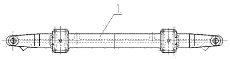
Fig. 7 is integrated main pin-and-hole axis body master's a view;
Fig. 8 is the vertical view of Fig. 7;
Fig. 9 is the front view of split type kingpin bore axis body;
Figure 10 is the vertical view of Fig. 9.
The specific embodiment
The present invention is further illustrated below in conjunction with accompanying drawing.
Referring to Fig. 1, Fig. 2, Fig. 3, Fig. 4, Fig. 5 and a kind of general boring grab shown in Figure 6, comprise clamp base 3, be located at clamp base left part and workpiece first positioning component above the right part with workpiece second positioning component, be located at left part in the clamp base and the first bushing plate positioning component and the second bushing plate positioning component (two modular constructions are consistent) above the middle right part respectively respectively, two bushing plates 11 are located by connecting with the upper end of the first bushing plate positioning component and the second bushing plate positioning component respectively.
The supplemental support 5 that described workpiece first positioning component is located at fixed pedestal upper end left part and right part by fixed pedestal 20, respectively and upper guide plate 6, be located at below the upper guide plate V-block 7 with pass the handle 4 that supplemental support 5 is connected with V-block 7 and form, its fixed pedestal 20 is located by connecting by pin and screw and clamp base 3;
Described workpiece second positioning component by regulate pedestal 23, respectively be located at the upper guide plate 6 of regulating pedestal upper end left part and right part and supplemental support 5, be located at below the upper guide plate V-block 7 with pass the handle 4 that supplemental support 5 is connected with V-block 7 and form, the both sides of regulating pedestal 23 bottom surfaces by T type bolt be located at that corresponding T type groove is connected on the clamp base 3, be located at the gathering sill of regulating middle part, pedestal 23 bottom surfaces and cooperate with first guide pad 18 above being located at clamp base 3, adjusting pedestal 23 can horizontally slip along first guide pad.
The described first bushing plate positioning component is made up of left base seat groove 24, the cylinder latch 9 and the rhombus latch 15 that are located on the left base seat groove 24 oral area edges, the both sides of base seat groove 24 bottom surfaces, a left side by T type bolt be located at that corresponding T type groove is connected on the clamp base 3, the gathering sill that is located at left base seat groove 24 bottom surfaces middle parts second guide pad 8 top with being located at clamp base 3 cooperates, and left base seat groove 24 can horizontally slip along second guide pad;
The described second bushing plate positioning component is made up of right base seat groove 16, the cylinder latch 9 and the rhombus latch 15 that are located on the right base seat groove 16 oral area edges, the both sides of right base seat groove 16 bottom surfaces by T type bolt be located at that corresponding T type groove is connected on the clamp base 3, the gathering sill that is located at right base seat groove 16 bottom surfaces middle parts three guide pad 17 top with being located at clamp base 3 cooperates, and right base seat groove can horizontally slip along the 3rd guide pad.
The two ends of described bushing plate 11 be respectively equipped with handle 25, middle part be provided with respectively with left base seat groove 24 and right base seat groove 16 on two cylinder latches 9 and corresponding locating hole 26 and a plurality of fabrication hole 27 of two rhombus latches 15; Bushing plate 11 is by two cylinder latches 9 and two rhombus latches 15 location on four locating holes on it 26 and left base seat groove 24 and the right base seat groove 16, and fixing by being located at bolt 12 on left base seat groove 24 and the right base seat groove 16 and nut 13 and packing ring 14.
Between left base seat groove 24 and right base seat groove 16, also be provided with the heel post 10 that is located by connecting on the clamp base 3; Heel post 10 is as product size C(dowel hole centre-to-centre spacing) indirect measuring basis B, when reality is used, because the size of measuring basis B is (the carrying out in the anchor clamps manufacturing) of fixing indirectly, according to product size A difference, guarantee that by slide left base seat groove 24 and right base seat groove 16 product size C gets final product, because A, B, C three's pass is: A=C+2B.
Between left base seat groove 24 and right base seat groove 16, also be provided with the pressing plate combination 21 that is located by connecting on the clamp base 3, be respectively equipped with location-plate 22 in the inboard of left base seat groove 24 and right base seat groove 16 bottom surfaces.
Described two cylinder latches 9 on left base seat groove 24 and the right base seat groove 16 notch edges and two the rhombus latches of being located at cooperates with latch lining 19 in the dowel hole that is located at left base seat groove 24 and right base seat groove 16 respectively.
Add man-hour, at first, unclamp the nut of pressing plate combination 21, product is lain on the location-plate 22 of anchor clamps, with the distance of tape measure drill jig positioning pedestal to the product two-end-point, fix the drill jig positioning pedestal on the left side after in roughly dividing with respect to V-type, the slide calliper rule of using 15000mm again are according to the size C that surveys between the column 10, adjust product leaf spring face centre-to-centre spacing A size like this, that is to say drill jig center size, fix the drill jig positioning pedestal on the right again, the V-type pedestal on fixing at last the right can be finely tuned V-type according to different products and to be made product size satisfy drawing to require back clamping platen combination, with cylinder latch 9 and rhombus latch 15 corresponding bushing plate 11 is navigated on the drill jig positioning pedestal, with two bolts, nuts and washers is fastening, at this moment just can process this kind product.Certainly, according to the product type difference, selected bushing plate 11 is also inequality, but basic principle all is consistent.
Embodiment one: referring to Fig. 1, Fig. 7 and Fig. 8, processed workpiece 1 is placed in left base seat groove 24 and the right base seat groove 16, the left end of workpiece 1 contacts with the V-block 7 of the first workpiece positioning component, the V-block 7 of right-hand member and the second workpiece positioning component) near; The bottom surface guarantees processed workpiece 1 level with location-plate 22 location, and fixing by pressing plate combination 21, can process.
Embodiment two: referring to Fig. 1, Fig. 9 and Figure 10, processed workpiece 2 is placed in left base seat groove 24 and the right base seat groove 16, the left end of workpiece 2 contacts with the V-block 7 of the first workpiece positioning component, the V-block 7 of right-hand member and the second workpiece positioning component near; The bottom surface guarantees processed workpiece 2 levels with location-plate 22 location, and fixing by pressing plate combination 21, can process.

Claims (7)

1.一种通用的钻孔夹具,包括夹具底座(3)、分别设在夹具底座左部和右部上面的工件第一定位组件和工件第二定位组件、分别设在夹具底座中左部和中右部上面的第一钻模板定位组件和第二钻模板定位组件,其特征是:两块钻模板(11)分别与第一钻模板定位组件和第二钻模板定位组件的上端定位连接。1. A general-purpose drilling jig, comprising a jig base (3), a workpiece first positioning assembly and a workpiece second positioning assembly respectively arranged on the left and right parts of the jig base, and respectively arranged on the left and right parts of the jig base. The first template positioning assembly and the second template positioning assembly on the middle right are characterized in that: two templates (11) are respectively connected to the upper ends of the first template positioning assembly and the second template positioning assembly. 2.根据权利要求1所述的一种通用的钻孔夹具,其特征是:所述工件第一定位组件由固定基座(20)、分别设在固定基座上端左部和右部的辅助支撑(5)和上导板(6)、设在上导板下面的V型块(7)和穿过辅助支撑(5)与V型块(7)连接的手柄(4)组成,其固定基座(20)通过销子和螺钉与夹具底座(3)定位连接;2. A universal drilling jig according to claim 1, characterized in that: the first positioning assembly of the workpiece is composed of a fixed base (20) and auxiliary parts respectively arranged on the left and right parts of the upper end of the fixed base. The support (5) is composed of the upper guide plate (6), the V-shaped block (7) arranged under the upper guide plate and the handle (4) connected to the V-shaped block (7) through the auxiliary support (5), and its fixed base (20) Position and connect with the fixture base (3) through pins and screws; 所述工件第二定位组件由调节基座(23)、分别设在调节基座上端左部和右部的上导板(6)和辅助支撑(5)、设在上导板下面的V型块(7)和穿过辅助支撑(5)与V型块(7)连接的手柄(4)组成,调节基座(23)底面的两侧通过T型螺栓与设在夹具底座(3)上相对应的T型槽配合连接,设在调节基座(23)底面中部的导向槽与设在夹具底座(3)上面的第一导向块(18)配合,调节基座(23)可以沿第一导向块左右滑动。The workpiece second positioning assembly consists of an adjustment base (23), an upper guide plate (6) and an auxiliary support (5) respectively arranged on the left and right parts of the upper end of the adjustment base, and a V-shaped block ( 7) and the handle (4) connected to the V-shaped block (7) through the auxiliary support (5), and the two sides of the bottom surface of the adjustment base (23) correspond to the fixture base (3) through T-bolts The T-shaped slots of the adjustment base (23) are matched with the first guide block (18) on the bottom surface of the adjustment base (23), and the adjustment base (23) can be guided along the first guide Blocks slide left and right. 3.根据权利要求1或2所述的一种通用的钻孔夹具,其特征是:所述第一钻模板定位组件由左基座槽(24)、设在左基座槽(24)口部边缘上的圆柱插销(9)和菱形插销(15)组成,左基座槽(24)底面的两侧通过T型螺栓与设在夹具底座(3)上相对应的T型槽配合连接,设在左基座槽(24)底面中部的导向槽与设在夹具底座(3)上面的第二导向块(8)配合,左基座槽(24)可以沿第二导向块左右滑动;3. A universal drilling jig according to claim 1 or 2, characterized in that: the first drilling template positioning component consists of a left base groove (24), and is located at the mouth of the left base groove (24). The cylindrical pin (9) and the rhombus pin (15) on the upper edge are composed, and the two sides of the bottom surface of the left base groove (24) are connected with the corresponding T-groove on the fixture base (3) through T-shaped bolts. The guide groove located in the middle of the bottom surface of the left base groove (24) cooperates with the second guide block (8) arranged on the fixture base (3), and the left base groove (24) can slide left and right along the second guide block; 所述第二钻模板定位组件由右基座槽(16)、设在右基座槽(16)口部边缘上的圆柱插销(9)和菱形插销(15)组成,右基座槽(16)底面的两侧通过T型螺栓与设在夹具底座(3)上相对应的T型槽配合连接,设在右基座槽(16)底面中部的导向槽与设在夹具底座(3)上面的第三导向块(17)配合,右基座槽可以沿第三导向块左右滑动。The second drilling template positioning assembly is composed of a right base groove (16), a cylindrical pin (9) and a rhombus pin (15) arranged on the mouth edge of the right base groove (16), and the right base groove (16) ) The two sides of the bottom surface are matched and connected with the corresponding T-shaped grooves on the fixture base (3) through T-shaped bolts, and the guide groove set in the middle of the bottom surface of the right base groove (16) is connected Cooperate with the third guide block (17), the right base groove can slide left and right along the third guide block. 4.根据权利要求1或2所述的一种通用的钻孔夹具,其特征是:所述钻模板(11)的两端分别设有把手(25)、中部设有分别与左基座槽(24)和右基座槽(16)上的两个圆柱插销(9)和两个菱形插销(15)对应的定位孔(26)、和多个工艺孔(27);钻模板(11)通过其上的四个定位孔(26)与左基座槽(24)和右基座槽(16)上的两个圆柱插销(9)和两个菱形插销(15)定位,并通过设在左基座槽(24)和右基座槽(16)上的螺栓(12)及螺母(13)和垫圈(14)固定。4. A universal drilling jig according to claim 1 or 2, characterized in that: the two ends of the drilling template (11) are respectively provided with handles (25), and the middle part is respectively provided with the left base groove (24) and the positioning holes (26) corresponding to the two cylindrical pins (9) and the two rhombic pins (15) on the right base groove (16), and a plurality of process holes (27); drilling template (11) Through the four positioning holes (26) on it and the two cylinder pins (9) and two rhombic pins (15) on the left base groove (24) and the right base groove (16) to locate, and through the The bolts (12), nuts (13) and washers (14) on the left base groove (24) and the right base groove (16) are fixed. 5.根据权利要求3所述的一种通用的钻孔夹具,其特征是:在左基座槽(24)和右基座槽(16)之间还设有定位连接在夹具底座(3)上的侧立柱(10)。5. A universal drilling jig according to claim 3, characterized in that: between the left base groove (24) and the right base groove (16), there is also a positioning connection on the jig base (3) Upper side column (10). 6.根据权利要求3所述的一种通用的钻孔夹具,其特征是:在左基座槽(24)和右基座槽(16)之间还设有定位连接在夹具底座(3)上的压板组合(21),在左基座槽(24)和右基座槽(16)底面的内侧分别设有定位板(22)。6. A universal drilling jig according to claim 3, characterized in that: between the left base groove (24) and the right base groove (16), there is also a positioning connection on the jig base (3) The pressing plate combination (21) on the top is respectively provided with a positioning plate (22) on the inner side of the bottom surface of the left base groove (24) and the right base groove (16). 7.根据权利要求3所述的一种通用的钻孔夹具,其特征是:所述设在左基座槽(24)和右基座槽(16)槽口部边缘上的两个圆柱插销(9)和两个菱形插销分别与设在左基座槽(24)和右基座槽(16)的定位销孔内的插销衬套(19)配合 7. A universal drilling jig according to claim 3, characterized in that: the two cylindrical pins arranged on the edge of the notches of the left base groove (24) and the right base groove (16) (9) and two rhombic bolts are respectively matched with the bolt bushings (19) located in the positioning pin holes of the left base groove (24) and the right base groove (16) .
CN 201010589509 2010-12-15 2010-12-15 General drill jig Expired - Fee Related CN102000856B (en)

Priority Applications (1)

Application Number Priority Date Filing Date Title
CN 201010589509 CN102000856B (en) 2010-12-15 2010-12-15 General drill jig

Applications Claiming Priority (1)

Application Number Priority Date Filing Date Title
CN 201010589509 CN102000856B (en) 2010-12-15 2010-12-15 General drill jig

Publications (2)

Publication Number Publication Date
CN102000856A true CN102000856A (en) 2011-04-06
CN102000856B CN102000856B (en) 2012-08-15

Family

ID=43808700

Family Applications (1)

Application Number Title Priority Date Filing Date
CN 201010589509 Expired - Fee Related CN102000856B (en) 2010-12-15 2010-12-15 General drill jig

Country Status (1)

Country Link
CN (1) CN102000856B (en)

Cited By (17)

* Cited by examiner, † Cited by third party
Publication number Priority date Publication date Assignee Title
CN102672495A (en) * 2012-05-28 2012-09-19 重庆大江工业有限责任公司 Universal fixture for processing plate spring inclined hole of heavy-duty automobile front axle
CN102689200A (en) * 2012-06-06 2012-09-26 沈阳飞机工业(集团)有限公司 Combined clamp for drilling hole of torque tube assembling unit product
CN102773728A (en) * 2012-07-02 2012-11-14 王庆 Device of drill front shaft master pin hole
CN102806373A (en) * 2012-08-30 2012-12-05 芜湖通和汽车管路系统有限公司 Drilling device for automobile pipeline and method for using drilling device
CN102950490A (en) * 2011-08-26 2013-03-06 吴江市海鑫机械有限公司 Adjustable gun barrel clamp
CN102990434A (en) * 2012-11-26 2013-03-27 无锡市航鹄科技有限公司 Multifunctional milling and cutting locating device
CN103658756A (en) * 2013-11-29 2014-03-26 无锡市航鹄科技有限公司 Fixture for drilling of complex workpieces
CN103737405A (en) * 2013-12-27 2014-04-23 柳江县龙满机械部件有限责任公司 Sleeve machining combination fixture
CN103753308A (en) * 2014-01-21 2014-04-30 重庆大江工业有限责任公司 Method for machining main pin holes of front axle of automobile
CN105057743A (en) * 2015-07-31 2015-11-18 重庆大江工业有限责任公司 Universal drilling clamp
CN105312627A (en) * 2014-08-01 2016-02-10 广东富华重工制造有限公司 Drilling clamp of axle-housing spring press plate
CN106735454A (en) * 2017-02-28 2017-05-31 成都航行机械制造有限公司 A kind of brill of heavy truck front axle attacks fixture
CN107097084A (en) * 2017-02-14 2017-08-29 江西昌河航空工业有限公司 A kind of quick positioning and processing method of long strut auricle joint
CN107671333A (en) * 2017-10-31 2018-02-09 重庆纵翼机械制造有限公司 Boring grab for balance shaft locating hole
CN110064948A (en) * 2019-05-30 2019-07-30 霍山嘉远智能制造有限公司 A kind of milling fixture with cylinder finger setting
CN114749999A (en) * 2022-04-18 2022-07-15 中航西安飞机工业集团股份有限公司 Distance measuring guide sleeve of automatic feeding drill and using method
CN114799284A (en) * 2021-11-26 2022-07-29 沪东中华造船(集团)有限公司 Adjustable right-angle oil hole drill jig and application method thereof

Citations (9)

* Cited by examiner, † Cited by third party
Publication number Priority date Publication date Assignee Title
JPH0215909A (en) * 1988-07-04 1990-01-19 Adachi Kensetsu Kogyo Kk Operation equipment for inside of circular pipe and working method with the operation equipment
CN2694252Y (en) * 2004-04-23 2005-04-20 中国重型汽车集团有限公司 Detecting instrument of automobile front axle
CN201183185Y (en) * 2007-09-03 2009-01-21 重庆长安金陵汽车零部件有限公司 Special fixture for welding automobile rear axle assembly
CN201192761Y (en) * 2008-04-14 2009-02-11 柳州五菱汽车工业有限公司 Follow-up fixture
CN101659014A (en) * 2009-07-07 2010-03-03 无锡动力工程股份有限公司 Prestressed boring bar clamp for processing camshaft holes of diesel engine
CN201470930U (en) * 2009-04-27 2010-05-19 福建畅丰车桥制造有限公司 Front axle leaf spring hole processing equipment
CN201618758U (en) * 2009-12-30 2010-11-03 上海和达汽车配件有限公司 Fixture for manufacturing mathematical model of automobile instrument panel transverse beam assembly
CN201618759U (en) * 2009-12-30 2010-11-03 上海和达汽车配件有限公司 Fixture for manufacturing left support and right support of automobile instrument panel transverse beam
CN201880967U (en) * 2010-12-15 2011-06-29 重庆大江工业有限责任公司 Universal drilling jig

Patent Citations (9)

* Cited by examiner, † Cited by third party
Publication number Priority date Publication date Assignee Title
JPH0215909A (en) * 1988-07-04 1990-01-19 Adachi Kensetsu Kogyo Kk Operation equipment for inside of circular pipe and working method with the operation equipment
CN2694252Y (en) * 2004-04-23 2005-04-20 中国重型汽车集团有限公司 Detecting instrument of automobile front axle
CN201183185Y (en) * 2007-09-03 2009-01-21 重庆长安金陵汽车零部件有限公司 Special fixture for welding automobile rear axle assembly
CN201192761Y (en) * 2008-04-14 2009-02-11 柳州五菱汽车工业有限公司 Follow-up fixture
CN201470930U (en) * 2009-04-27 2010-05-19 福建畅丰车桥制造有限公司 Front axle leaf spring hole processing equipment
CN101659014A (en) * 2009-07-07 2010-03-03 无锡动力工程股份有限公司 Prestressed boring bar clamp for processing camshaft holes of diesel engine
CN201618758U (en) * 2009-12-30 2010-11-03 上海和达汽车配件有限公司 Fixture for manufacturing mathematical model of automobile instrument panel transverse beam assembly
CN201618759U (en) * 2009-12-30 2010-11-03 上海和达汽车配件有限公司 Fixture for manufacturing left support and right support of automobile instrument panel transverse beam
CN201880967U (en) * 2010-12-15 2011-06-29 重庆大江工业有限责任公司 Universal drilling jig

Non-Patent Citations (2)

* Cited by examiner, † Cited by third party
Title
《机械制造》 20040531 华健等 派力奥轿车后横梁与轴头焊接夹具设计及焊枪与夹具的干涉运动检验 第42卷, 第477期 2 *
《轻型汽车技术》 20020228 王顺国等 可调错模角的汽车前轴铣削夹具及设备的研制 第19-22页 , 第2期 2 *

Cited By (25)

* Cited by examiner, † Cited by third party
Publication number Priority date Publication date Assignee Title
CN102950490A (en) * 2011-08-26 2013-03-06 吴江市海鑫机械有限公司 Adjustable gun barrel clamp
CN102672495A (en) * 2012-05-28 2012-09-19 重庆大江工业有限责任公司 Universal fixture for processing plate spring inclined hole of heavy-duty automobile front axle
CN102672495B (en) * 2012-05-28 2014-03-05 重庆大江工业有限责任公司 A Universal Fixture for Machining Inclined Holes of Front Axle Springs of Heavy Vehicles
CN102689200A (en) * 2012-06-06 2012-09-26 沈阳飞机工业(集团)有限公司 Combined clamp for drilling hole of torque tube assembling unit product
CN102689200B (en) * 2012-06-06 2014-02-26 沈阳飞机工业(集团)有限公司 Combined clamp for drilling hole of torque tube assembling unit product
CN102773728A (en) * 2012-07-02 2012-11-14 王庆 Device of drill front shaft master pin hole
CN102806373B (en) * 2012-08-30 2015-08-26 芜湖通和汽车管路系统有限公司 A kind of drilling equipment being used for automobile pipeline that utilizes carries out the method for holing
CN102806373A (en) * 2012-08-30 2012-12-05 芜湖通和汽车管路系统有限公司 Drilling device for automobile pipeline and method for using drilling device
CN102990434A (en) * 2012-11-26 2013-03-27 无锡市航鹄科技有限公司 Multifunctional milling and cutting locating device
CN103658756A (en) * 2013-11-29 2014-03-26 无锡市航鹄科技有限公司 Fixture for drilling of complex workpieces
CN103737405A (en) * 2013-12-27 2014-04-23 柳江县龙满机械部件有限责任公司 Sleeve machining combination fixture
CN103737405B (en) * 2013-12-27 2016-06-29 柳江县龙满机械部件有限责任公司 One kind set class modular fixture
CN103753308A (en) * 2014-01-21 2014-04-30 重庆大江工业有限责任公司 Method for machining main pin holes of front axle of automobile
CN103753308B (en) * 2014-01-21 2016-01-20 重庆大江工业有限责任公司 A kind of processing method of automobile front axle kingpin bore
CN105312627B (en) * 2014-08-01 2018-04-03 广东富华重工制造有限公司 Axle housing spring bearer plate boring grab
CN105312627A (en) * 2014-08-01 2016-02-10 广东富华重工制造有限公司 Drilling clamp of axle-housing spring press plate
CN105057743A (en) * 2015-07-31 2015-11-18 重庆大江工业有限责任公司 Universal drilling clamp
CN107097084A (en) * 2017-02-14 2017-08-29 江西昌河航空工业有限公司 A kind of quick positioning and processing method of long strut auricle joint
CN106735454A (en) * 2017-02-28 2017-05-31 成都航行机械制造有限公司 A kind of brill of heavy truck front axle attacks fixture
CN107671333A (en) * 2017-10-31 2018-02-09 重庆纵翼机械制造有限公司 Boring grab for balance shaft locating hole
CN107671333B (en) * 2017-10-31 2019-03-26 重庆纵翼机械制造有限公司 Drilling fixture for balanced axis positioning holes
CN110064948A (en) * 2019-05-30 2019-07-30 霍山嘉远智能制造有限公司 A kind of milling fixture with cylinder finger setting
CN114799284A (en) * 2021-11-26 2022-07-29 沪东中华造船(集团)有限公司 Adjustable right-angle oil hole drill jig and application method thereof
CN114749999A (en) * 2022-04-18 2022-07-15 中航西安飞机工业集团股份有限公司 Distance measuring guide sleeve of automatic feeding drill and using method
CN114749999B (en) * 2022-04-18 2023-06-23 中航西安飞机工业集团股份有限公司 Distance measuring guide sleeve of automatic feeding drill and use method

Also Published As

Publication number Publication date
CN102000856B (en) 2012-08-15

Similar Documents

Publication Publication Date Title
CN102000856A (en) General drill jig
CN201880967U (en) Universal drilling jig
CN203578858U (en) Drilling fixture
CN203045361U (en) Spring supporting rotation-clamping floating fixture
CN205147887U (en) Bearing retainer's machining anchor clamps
CN206982231U (en) Numerical control end-face milling drill centres machine tool clamp floating click-on mechanism
CN205020874U (en) But graduation bores mechanism in radial hole
CN202894837U (en) Clamp for machining phi-30mm auxiliary hole of rear leaf spring shackle
CN201128071Y (en) Clamping structure for processing slant hole
CN213592345U (en) A jig for lathe machining of tee joint
CN206484064U (en) A kind of clamping device of the brill circumferential apertures of workpiece
CN218284640U (en) Machining device for special-shaped floating thrust tile characteristic inclined plane
CN216656463U (en) Simple mould for drilling multiple holes in sunken arc-shaped sheet
CN208083908U (en) A kind of 5-axis machining center special fixture
CN207255758U (en) A four-axis vacuum fixture
CN215393844U (en) Boring machine fixture for machining two holes of support shell
CN206425841U (en) A high-precision carving fixture
CN204235234U (en) A kind of cylinder bore finishing fixture
CN204711287U (en) Cross recess gear batch machining drilling jig device
CN113909536A (en) Simple mould for drilling multiple holes in sunken arc-shaped sheet
CN204546050U (en) The universal milling machine frock clamp of aviation part
CN202428206U (en) Clamp
CN214977835U (en) Machine tool chuck used for mechanical manufacturing and accurate in positioning
CN107914031B (en) Drill jig for processing high-precision inclined hole
CN224169271U (en) Go up guide wheel frame location frock

Legal Events

Date Code Title Description
C06 Publication
PB01 Publication
C10 Entry into substantive examination
SE01 Entry into force of request for substantive examination
C14 Grant of patent or utility model
GR01 Patent grant
EE01 Entry into force of recordation of patent licensing contract

Application publication date: 20110406

Assignee: CHONGQING DAJIANG XINDA VEHICLE Ltd.

Assignor: CHONGQING DAJIANG INDUSTRY Co.,Ltd.

Contract record no.: 2013500000004

Denomination of invention: General drill jig

Granted publication date: 20120815

License type: Exclusive License

Record date: 20130320

LICC Enforcement, change and cancellation of record of contracts on the licence for exploitation of a patent or utility model
TR01 Transfer of patent right

Effective date of registration: 20190515

Address after: 401321 Fenghua Road, Yudong, Banan District, Chongqing, 901

Patentee after: CHONGQING DAJIANG AXLE Co.,Ltd.

Address before: 401321 Chongqing Banan District Chongqing Dajiang Industrial Co., Ltd. Technology Department

Patentee before: CHONGQING DAJIANG INDUSTRY Co.,Ltd.

TR01 Transfer of patent right
CF01 Termination of patent right due to non-payment of annual fee

Granted publication date: 20120815

CF01 Termination of patent right due to non-payment of annual fee