CN102000947A - Method for milling two half bushes - Google Patents
Method for milling two half bushes Download PDFInfo
- Publication number
- CN102000947A CN102000947A CN 201010506832 CN201010506832A CN102000947A CN 102000947 A CN102000947 A CN 102000947A CN 201010506832 CN201010506832 CN 201010506832 CN 201010506832 A CN201010506832 A CN 201010506832A CN 102000947 A CN102000947 A CN 102000947A
- Authority
- CN
- China
- Prior art keywords
- milling
- bearing shell
- bush
- tubular blank
- processing
- Prior art date
- Legal status (The legal status is an assumption and is not a legal conclusion. Google has not performed a legal analysis and makes no representation as to the accuracy of the status listed.)
- Granted
Links
- 238000003801 milling Methods 0.000 title claims abstract description 67
- 238000000034 method Methods 0.000 title claims abstract description 10
- 239000000463 material Substances 0.000 abstract description 4
- 230000002708 enhancing effect Effects 0.000 abstract 1
- 238000004519 manufacturing process Methods 0.000 abstract 1
- 238000010586 diagram Methods 0.000 description 5
- 238000003754 machining Methods 0.000 description 4
- 239000002699 waste material Substances 0.000 description 3
- 238000005516 engineering process Methods 0.000 description 1
- 238000000227 grinding Methods 0.000 description 1
- 238000003672 processing method Methods 0.000 description 1
Images




Landscapes
- Milling Processes (AREA)
Abstract
The invention relates to a method for milling two half bushes. The method comprises the following steps of: 1) processing a bush inner hole and an outer circle with a bar stock; 2) performing a first bush milling step, namely, arranging a bush of which the inner hole and the outer diameter are processed on a central spindle, arranging the bush on a milling machine table and aligning the right side of a milling blade over against the center of a tubular blank of the bush for milling; 3) performing a second bush milling step, namely, moving a transverse milling machine table backward by S and rotating the tubular blank of the bush clockwise by an angle of alpha for milling; 4) performing a third bush milling step, namely, moving the transverse milling machine table forward by a half B of the opening size value of the tubular blank of the bush and rotating the tubular blank of the bush clockwise by 180 degree-alpha for milling; and 5) performing a fourth bush milling step, namely, moving the transverse milling machine table backward by 2B-S and rotating the tubular blank of the bush clockwise by an angle of alpha for milling. The method has the advantages of saving materials, lowering production cost and enhancing the processing accuracy of a main spindle bush.
Description
Technical field:
The present invention is the method for the two halves formula main shaft bearing shell used of processing excircles grinding machine.
Background technology:
The main shaft bearing shell of cylindrical grinder is two semicircular structures, divide top bearing shell and lower bearing, by top bearing shell and lower bearing is one group of main shaft bearing shell, when repairing, need process two semicircular main shaft bearing shell top bearing shells and lower bearing again, change the main shaft bearing shell of wearing and tearing, the processing method that adopted of machining spindle bearing shell was just can be processed into one group of main shaft bearing shell with two round bars in the past, become the bearing shell tubular blank behind endoporus by the roughing bearing shell and the cylindrical, on milling machine, the bearing shell tubular blank is cut with milling cutter, half that will meet the requirement of bearing shell design drawing stays, with do not meet the requirement of bearing shell design drawing second half as waste disposal, reprocess second half main shaft bearing shell with another root bar again, constitute one group of main shaft bearing shell, so waste material, waste time and energy the endoporus of the main shaft bearing shell that is processed into two bars again, cylindrical and length all can be prone to error, influence the machining accuracy of bearing shell.
Summary of the invention:
The milling method that the purpose of this invention is to provide a kind of two halves bearing shell of energy economical with materials; The objective of the invention is to realize by following technical scheme: the milling method of two halves bearing shell, its step is as follows:
1), processing bearing shell endoporus and cylindrical: with the endoporus and the external diameter of bar processing bearing shell;
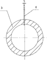
2), bearing shell milling first step processing: the bearing shell tubular blank that will process endoporus and external diameter is contained on the mandrel, and is contained on the milling machine table, and the cutter blade right flank aligns bearing shell tubular blank center, the thick S of cutter blade, milling processing;
3), bearing shell milling second step processing: with the mobile backward S of milling machine horizontal work level, the bearing shell tubular blank is clockwise rotated the α angle, milling processing;
4), bearing shell milling the 3rd step processing: the milling machine horizontal work level is moved forward half B of bearing shell tubular blank opening size value, the bearing shell tubular blank is clockwise rotated 180 °-α, milling processing;
5), bearing shell milling the 4th step processing: with the mobile backward 2B-S of milling machine horizontal work level, the bearing shell tubular blank is clockwise rotated the α angle, milling processing.
Advantage of the present invention: be the main shaft bearing shell that adopts cylindrical grinder that a round bar can be processed into two semicircular structures to use, saved material, reduced the generation cost, and improved the machining accuracy of main shaft bearing shell.
Description of drawings:
Fig. 1 is one group of main shaft bearing shell of cylindrical grinder combining structure cross-sectional schematic;
Fig. 2 is the A-A cross-sectional schematic of Fig. 1;
Fig. 3 is the B-B cross-sectional schematic of Fig. 1;
Fig. 4 is that the bearing shell tubular blank is installed in and treats the milling schematic diagram on the milling machine;
Fig. 5 is a bearing shell tubular blank milling first step processing schematic diagram;
Fig. 6 is bearing shell tubular blank milling second step processing schematic diagram;
Fig. 7 is bearing shell tubular blank milling the 3rd a step processing schematic diagram;
Fig. 8 is bearing shell tubular blank milling the 4th a step processing schematic diagram;
Fig. 9 is one group of main shaft bearing shell of the cylindrical grinder combining structure cross-sectional schematic that machines.
Among the figure: 1, in top bearing shell 2, lower bearing 3, bearing shell tubular blank 4, cutter blade D, bearing shell outside diameter d, the bearing shell 1/2 A/F B=3mm α after circular diameter B, the bearing shell milling, bearing shell milling second step processing intermediate bushing tubular blank clockwise rotate angle [alpha] S, cutter blade thickness 6, cutter shaft 7, common horizontal milling machine 8, horizontal work level 9, part dextrorotation veer 10, horizontal work level backward directions 11, horizontal work level forwards to
The specific embodiment:
With one group of main shaft bearing shell of cylindrical grinder diameter of bore d=74.5mm, main shaft bearing shell outside diameter D=101.1mm is an example:
The milling method of two halves bearing shell, its step is as follows:
1), processing bearing shell endoporus and cylindrical: diameter of bore d=74.5mm and outside diameter D=101.1mm with bar processing bearing shell become the bearing shell tubular blank;
2), bearing shell milling first step processing: the bearing shell tubular blank that will process endoporus and cylindrical is contained on the mandrel, the external diameter of mandrel is H7/f7 with cooperating of the endoporus of bearing shell, and be contained on the milling machine table, the cutter blade right flank aligns bearing shell tubular blank center, the thick S=2mm of cutter blade, milling processing;
3), bearing shell milling second step processing:, the bearing shell tubular blank is clockwise rotated α angle α=2DarcSin2B/D ÷ (D+d)=3 ° 55 ', milling processing with the mobile backward S=2mm of milling machine horizontal work level;
4), the processing of bearing shell milling the 3rd step: the milling machine horizontal work level is moved forward half B=3mm of bearing shell tubular blank opening size value, the bearing shell tubular blank is clockwise rotated 180 °-α, promptly 180 °-3 ° 55 '=176 ° 05 ', milling processing;
5), the processing of bearing shell milling the 4th step: with the horizontal backward mobile 2B-S of milling machine table, promptly 2 * 3mm-2mm=4mm clockwise rotates the α angle with the bearing shell tubular blank, promptly rotate 3 ° 55 ', milling processing.
The 4th the step process top bearing shell is rotated counterclockwise 3 ° 55 ', two common faces of bearing shell are fitted, making in addition, the distance on two planes becomes 2B=6mm, satisfied the requirement of bearing shell design drawing, saved material, reduce the generation cost, eliminated the error of endoporus, cylindrical and the length processing appearance of main shaft bearing shell, improved the machining accuracy of main shaft bearing shell.
Claims (1)
1. the milling method of two halves bearing shell, its step is as follows:
1), processing bearing shell endoporus and cylindrical: with the endoporus and the external diameter of bar processing bearing shell;
2), bearing shell milling first step processing: the bearing shell tubular blank that will process endoporus and external diameter is contained on the mandrel, and is contained on the milling machine table, and the cutter blade right flank aligns bearing shell tubular blank center, the thick S of cutter blade, milling processing;
3), bearing shell milling second step processing: with the mobile backward S of milling machine horizontal work level, the bearing shell tubular blank is clockwise rotated the α angle, milling processing;
4), bearing shell milling the 3rd step processing: the milling machine horizontal work level is moved forward half B of bearing shell tubular blank opening size value, the bearing shell tubular blank is clockwise rotated 180 °-α, milling processing;
5), bearing shell milling the 4th step processing: with the mobile backward 2B-S of milling machine horizontal work level, the bearing shell tubular blank is clockwise rotated the α angle, milling processing.
Priority Applications (1)
| Application Number | Priority Date | Filing Date | Title |
|---|---|---|---|
| CN2010105068322A CN102000947B (en) | 2010-10-14 | 2010-10-14 | Method for milling two half bushes |
Applications Claiming Priority (1)
| Application Number | Priority Date | Filing Date | Title |
|---|---|---|---|
| CN2010105068322A CN102000947B (en) | 2010-10-14 | 2010-10-14 | Method for milling two half bushes |
Publications (2)
| Publication Number | Publication Date |
|---|---|
| CN102000947A true CN102000947A (en) | 2011-04-06 |
| CN102000947B CN102000947B (en) | 2012-06-06 |
Family
ID=43808788
Family Applications (1)
| Application Number | Title | Priority Date | Filing Date |
|---|---|---|---|
| CN2010105068322A Expired - Fee Related CN102000947B (en) | 2010-10-14 | 2010-10-14 | Method for milling two half bushes |
Country Status (1)
| Country | Link |
|---|---|
| CN (1) | CN102000947B (en) |
Cited By (1)
| Publication number | Priority date | Publication date | Assignee | Title |
|---|---|---|---|---|
| TWI707692B (en) * | 2014-05-13 | 2020-10-21 | 英商梅迪繆思有限公司 | Anti-b7-h1 and anti-ctla-4 antibodies for treating non-small cell lung cancer |
Citations (4)
| Publication number | Priority date | Publication date | Assignee | Title |
|---|---|---|---|---|
| CN1243922A (en) * | 1999-08-18 | 2000-02-09 | 张世平 | Technology for manufacturing new-type bush dedicated to main bearing of ball grinding mill |
| JP2001070813A (en) * | 1999-09-06 | 2001-03-21 | Kurimoto Ltd | Structure for supporting roller of vertical mill |
| CN101021233A (en) * | 2006-11-02 | 2007-08-22 | 湘潭市岳塘区兴盛液压机械配件加工厂 | Processing technology for deformed tiltable bush |
| CN201442192U (en) * | 2009-04-10 | 2010-04-28 | 沈阳黎航发石化机械设备制造有限公司 | Device for processing tilting pad |
-
2010
- 2010-10-14 CN CN2010105068322A patent/CN102000947B/en not_active Expired - Fee Related
Patent Citations (4)
| Publication number | Priority date | Publication date | Assignee | Title |
|---|---|---|---|---|
| CN1243922A (en) * | 1999-08-18 | 2000-02-09 | 张世平 | Technology for manufacturing new-type bush dedicated to main bearing of ball grinding mill |
| JP2001070813A (en) * | 1999-09-06 | 2001-03-21 | Kurimoto Ltd | Structure for supporting roller of vertical mill |
| CN101021233A (en) * | 2006-11-02 | 2007-08-22 | 湘潭市岳塘区兴盛液压机械配件加工厂 | Processing technology for deformed tiltable bush |
| CN201442192U (en) * | 2009-04-10 | 2010-04-28 | 沈阳黎航发石化机械设备制造有限公司 | Device for processing tilting pad |
Cited By (1)
| Publication number | Priority date | Publication date | Assignee | Title |
|---|---|---|---|---|
| TWI707692B (en) * | 2014-05-13 | 2020-10-21 | 英商梅迪繆思有限公司 | Anti-b7-h1 and anti-ctla-4 antibodies for treating non-small cell lung cancer |
Also Published As
| Publication number | Publication date |
|---|---|
| CN102000947B (en) | 2012-06-06 |
Similar Documents
| Publication | Publication Date | Title |
|---|---|---|
| CN103008741B (en) | Machining process of middle-long thin-wall blades | |
| CN101596608A (en) | A kind of grooving cutter device that is used to process cannelure | |
| CN101722420A (en) | Manufacturing method of split-type gear case body | |
| CN102615362A (en) | Internal screw thread processing method | |
| CN104259778A (en) | Machining method of bearing shell of turbocharger | |
| CN204673092U (en) | High-accuracy high-efficiency herringbone bear machining tool | |
| CN203636106U (en) | High-precision gear and rack tooth milling machine | |
| CN201295781Y (en) | Boring and milling mechanism for spherical inner bores | |
| CN201291308Y (en) | Finish-boring hole scudding knife | |
| CN102000947A (en) | Method for milling two half bushes | |
| CN204018752U (en) | Fine-tuning sphere swings boring cutter | |
| CN202539720U (en) | Internal thread machining device | |
| CN202045426U (en) | Bore slot scraping knife | |
| CN201895131U (en) | Three-blade end mill | |
| CN202684235U (en) | Numerical-control gulleting machine tool rest mechanism of large-sized cylindrical gear | |
| CN205816834U (en) | A kind of compound tool | |
| CN104889461A (en) | All-metal screw pump rotor milling method and device | |
| CN201609783U (en) | Device for processing long inner bore keyway of roller | |
| CN204711219U (en) | A kind of double-headstock numerically controlled lathe adjustable blade holders | |
| CN101972862B (en) | Bearing bush finely-bored inside diameter skiving process | |
| CN201711625U (en) | S-shaped internal thread ball end mill | |
| CN204122777U (en) | A kind of arc profile automatic imitation is harnessed an animal to a cart boring cutter | |
| CN205764064U (en) | A kind of boring cutter body for deep hole machining stepped hole tapering arc transition | |
| CN201807754U (en) | Processing tool for boring high-precision multi-gear shaft holes | |
| CN102009196A (en) | Back spot facing machining cutter and application method thereof |
Legal Events
| Date | Code | Title | Description |
|---|---|---|---|
| C06 | Publication | ||
| PB01 | Publication | ||
| C10 | Entry into substantive examination | ||
| SE01 | Entry into force of request for substantive examination | ||
| C14 | Grant of patent or utility model | ||
| GR01 | Patent grant | ||
| CF01 | Termination of patent right due to non-payment of annual fee |
Granted publication date: 20120606 Termination date: 20141014 |
|
| EXPY | Termination of patent right or utility model |