CN102012307A - Supersonic speed boundary layer wind tunnel - Google Patents
Supersonic speed boundary layer wind tunnel Download PDFInfo
- Publication number
- CN102012307A CN102012307A CN 201010551282 CN201010551282A CN102012307A CN 102012307 A CN102012307 A CN 102012307A CN 201010551282 CN201010551282 CN 201010551282 CN 201010551282 A CN201010551282 A CN 201010551282A CN 102012307 A CN102012307 A CN 102012307A
- Authority
- CN
- China
- Prior art keywords
- boundary layer
- wind tunnel
- supersonic speed
- section
- tunnel according
- Prior art date
- Legal status (The legal status is an assumption and is not a legal conclusion. Google has not performed a legal analysis and makes no representation as to the accuracy of the status listed.)
- Granted
Links
- 230000002093 peripheral effect Effects 0.000 claims abstract description 23
- 238000002474 experimental method Methods 0.000 claims abstract description 22
- 230000007704 transition Effects 0.000 claims abstract description 18
- 238000011144 upstream manufacturing Methods 0.000 claims description 27
- 239000005304 optical glass Substances 0.000 claims description 8
- 238000012360 testing method Methods 0.000 abstract description 38
- 230000003287 optical effect Effects 0.000 abstract description 12
- 238000005516 engineering process Methods 0.000 abstract description 10
- 239000012530 fluid Substances 0.000 abstract description 5
- 230000006641 stabilisation Effects 0.000 abstract description 3
- 238000011105 stabilization Methods 0.000 abstract description 3
- 238000011160 research Methods 0.000 description 13
- 230000000087 stabilizing effect Effects 0.000 description 7
- 238000000034 method Methods 0.000 description 6
- 230000000694 effects Effects 0.000 description 5
- 230000035939 shock Effects 0.000 description 5
- 230000009286 beneficial effect Effects 0.000 description 4
- 239000007789 gas Substances 0.000 description 4
- 230000007246 mechanism Effects 0.000 description 4
- 230000001133 acceleration Effects 0.000 description 3
- 238000010586 diagram Methods 0.000 description 3
- 230000006872 improvement Effects 0.000 description 3
- 239000004576 sand Substances 0.000 description 3
- 230000015572 biosynthetic process Effects 0.000 description 2
- 238000007664 blowing Methods 0.000 description 2
- 238000011161 development Methods 0.000 description 2
- 239000000463 material Substances 0.000 description 2
- 238000012986 modification Methods 0.000 description 2
- 230000004048 modification Effects 0.000 description 2
- 230000008569 process Effects 0.000 description 2
- 238000000926 separation method Methods 0.000 description 2
- 230000003746 surface roughness Effects 0.000 description 2
- 229910000831 Steel Inorganic materials 0.000 description 1
- 230000008602 contraction Effects 0.000 description 1
- 230000023077 detection of light stimulus Effects 0.000 description 1
- 230000008030 elimination Effects 0.000 description 1
- 238000003379 elimination reaction Methods 0.000 description 1
- 238000003384 imaging method Methods 0.000 description 1
- 238000005259 measurement Methods 0.000 description 1
- 239000002245 particle Substances 0.000 description 1
- 230000010349 pulsation Effects 0.000 description 1
- 230000009467 reduction Effects 0.000 description 1
- 239000010959 steel Substances 0.000 description 1
- 230000001629 suppression Effects 0.000 description 1
- 238000012800 visualization Methods 0.000 description 1
Images

Landscapes
- Aerodynamic Tests, Hydrodynamic Tests, Wind Tunnels, And Water Tanks (AREA)
Abstract
本发明提供了一种超声速边界层风洞,包括过渡段(1),用于引入气流,并对气流进行第一级整流;稳定段(2),连接在所述过渡段(1)的下游,用于对气流进行第二级整流;以及喷管实验段(3),连接在所述稳定段(2)的下游,包括:喷管部(31),构造成单边膨胀喷管结构,实验部(32),所述实验部(32)的周壁形成有透明窗口,以及边界层平板(33),设置在所述喷管实验段(3)的内腔中,从所述喷管部(31)延伸到所述实验部(32)中,能够实现边界层流态控制,并且便于光学非接触测试技术的实施。
The invention provides a supersonic boundary layer wind tunnel, comprising a transition section (1), used to introduce airflow, and perform first-stage rectification to the airflow; a stabilization section (2), connected downstream of the transition section (1) , for carrying out second-stage rectification to the airflow; and the nozzle experiment section (3), connected downstream of the stable section (2), including: nozzle part (31), configured as a unilateral expansion nozzle structure, Experiment part (32), the peripheral wall of described experiment part (32) is formed with transparent window, and boundary layer plate (33), is arranged in the inner chamber of described nozzle experiment section (3), from described nozzle part (31) extending into the experiment part (32), can realize boundary layer fluid state control, and facilitate the implementation of optical non-contact testing technology.
Description
技术领域technical field
本发明涉及一种风洞,尤其涉及一种超声速边界层风洞。The invention relates to a wind tunnel, in particular to a supersonic boundary layer wind tunnel.
背景技术Background technique
随着现代空气动力学技术的发展,空气动力学机理问题研究越来越重要,作为典型的可压缩剪切流动,超声速边界层研究不仅具有广泛的应用背景而且具有重要理论意义。可压缩性对边界层流场精细结构的影响规律还存在争论,边界层流场精细结构与边界层动力学特征之间的关系还有待深入研究。一百多年的边界层研究表明,边界层尤其是超声速边界层中仍然存在大量未被认清的问题,这些问题困扰流体力学科研人员的同时,也对边界层的工程应用提出了越来越严峻的挑战。超声速边界层的实验研究亟待深入开展。With the development of modern aerodynamic technology, the study of aerodynamic mechanism is becoming more and more important. As a typical compressible shear flow, the study of supersonic boundary layer not only has a wide application background but also has important theoretical significance. The influence of compressibility on the fine structure of the boundary layer flow field is still controversial, and the relationship between the fine structure of the boundary layer flow field and the dynamic characteristics of the boundary layer needs to be further studied. More than 100 years of boundary layer research has shown that there are still a large number of unrecognized problems in the boundary layer, especially in the supersonic boundary layer. Serious challenges. Experimental research on the supersonic boundary layer needs to be carried out in depth.
超声速边界层具有三维、非定常和多尺度的特征,定量流动成像技术是研究这些特征的重要手段,它需要边界层风洞具有良好的光学测量环境,相应的风洞光学窗口需要针对研究对象的特点进行设计。The supersonic boundary layer has three-dimensional, unsteady and multi-scale characteristics. Quantitative flow imaging technology is an important means to study these characteristics. It requires a good optical measurement environment in the boundary layer wind tunnel, and the corresponding wind tunnel optical window needs to be specific to the research object. Features are designed.
从边界层生成的方法来看,现有边界层实验模型主要有两大类:一类是将产生边界层的平板或圆锥等模型放到风洞实验段中进行研究,另一类是直接对风洞壁面自身产生的边界层进行研究。From the perspective of boundary layer generation methods, there are two main types of existing boundary layer experimental models: one is to put the flat plate or cone model that generates the boundary layer into the wind tunnel experiment section for research, and the other is to directly The boundary layer generated by the wind tunnel wall itself is studied.
文章“M.Yoda,J.Westerweel,Particle image velocimetry studies of a boundary layer perturbed by localized suction,Experiments in Fluids.30:239-245,2001.”设计了一个用于流动控制研究的200mm×60mm低速边界层平板模型,安装在低速风洞实验段中,模型下表面距风洞壁面70mm,采用两个底座固定支撑。The article "M.Yoda, J.Westerweel, Particle image velocity studies of a boundary layer perturbed by localized suction, Experiments in Fluids.30: 239-245, 2001." designed a 200mm×60mm low-velocity boundary for flow control research The layered slab model is installed in the low-speed wind tunnel test section. The lower surface of the model is 70mm away from the wind tunnel wall, and it is supported by two bases.
文章“M.W.Smith,A.J.Smits,Visualization of the structure of supersonic turbulent boundary layers.Experiments in Fluids18:288-302,1995”开展了两组超声速边界层实验研究。第一组研究是在Princeton大学200mm×200mm的下吹式超声速风洞壁面上进行的,实验区域距离喷管出口1.9m,当地边界层厚度28mm,基于动量损失厚度的雷诺数为81900,速度为580m/s,马赫数2.82。另外一组直接研究实验段截面为13mm×26mm的超声速风洞壁面边界层,在观察区域的四壁开有光学窗口,以便于光学测试技术的实施,观察区域处边界层厚度为4.2mm,基于动量损失厚度定义的雷诺数为25000。The article "M.W.Smith, A.J.Smits, Visualization of the structure of supersonic turbulent boundary layers. Experiments in Fluids18: 288-302, 1995" carried out two sets of supersonic boundary layer experimental studies. The first group of research was carried out on the wall of a 200mm×200mm down-blowing supersonic wind tunnel at Princeton University. The experimental area was 1.9m away from the nozzle exit, and the local boundary layer thickness was 28mm. The Reynolds number based on the momentum loss thickness was 81900, and the velocity was 580m/s, Mach number 2.82. Another group of direct research experiment section is the supersonic wind tunnel wall boundary layer with a section of 13 mm × 26 mm. Optical windows are opened on the four walls of the observation area to facilitate the implementation of optical testing techniques. The thickness of the boundary layer in the observation area is 4.2 mm. Based on The Reynolds number defined by the momentum loss thickness is 25000.
文章“D.Heitmann et al.,Non-intrusive generation of instability waves in a planar hypersonic boundary layer.Experiments in Fluids,Published online:05 August 2010.”开展了高超声速边界层流场的研究,其边界层模型为630mm×200mm的钢制平板,前缘斜切角为10°,模型前端两侧安装330mm×70mm的侧翼,以抑制三维效应对边界层的影响,整个边界层模型安装在HBL高超声速风洞的实验段中。The article "D.Heitmann et al., Non-intrusive generation of instability waves in a planar hypersonic boundary layer. Experiments in Fluids, Published online: 05 August 2010." carried out research on hypersonic boundary layer flow field, and its boundary layer model It is a 630mm×200mm steel flat plate with a chamfer angle of 10° at the front edge, and 330mm×70mm flanks are installed on both sides of the front end of the model to suppress the influence of the three-dimensional effect on the boundary layer. The entire boundary layer model is installed in the HBL hypersonic wind tunnel in the experimental section.
基于模型的边界层实验研究方法的主要问题在于:一、超声速流场中边界层前缘不可避免的产生激波,该激波经过壁面或自由射流边界反射后会与边界层相互作用,产生复杂的流场结构,不利于边界层自身精细结构的研究;二、因为风洞并不是针对边界层研究所设计的,相应的实验舱一般较大,不利于采用光学非接触测试技术对边界层精细结构进行观测;三、某些下吹式风洞雷诺数较大,流场未经降噪处理,严重影响边界层的转捩与失稳特性,不利于机理研究。The main problems of the model-based boundary layer experimental research method are as follows: 1. The front edge of the boundary layer in the supersonic flow field inevitably produces shock waves, which will interact with the boundary layer after being reflected by the wall or free jet boundary, resulting in complex The flow field structure is not conducive to the study of the fine structure of the boundary layer; second, because the wind tunnel is not designed for the study of the boundary layer, the corresponding experimental chamber is generally large, which is not conducive to the use of optical non-contact testing technology to study the fine structure of the boundary layer. Third, the Reynolds number of some down-blowing wind tunnels is relatively large, and the flow field has not been treated for noise reduction, which seriously affects the transition and instability characteristics of the boundary layer, which is not conducive to mechanism research.
直接采用风洞壁面产生边界层进行研究,虽然克服了激波干扰的问题,但难以采用光学手段观测喷管内部边界层,这对研究上游流场结构对边界层的影响是十分不利的。除此之外,现有风洞的宽高比接近1,两侧壁边界层的发展严重干扰边界层的流场结构,同样不利于机理研究。Although the problem of shock wave interference is overcome by directly using the boundary layer generated by the wall of the wind tunnel, it is difficult to observe the boundary layer inside the nozzle by optical means, which is very unfavorable for the study of the influence of the upstream flow field structure on the boundary layer. In addition, the aspect ratio of the existing wind tunnel is close to 1, and the development of the boundary layer on both side walls seriously interferes with the flow field structure of the boundary layer, which is also unfavorable for mechanism research.
发明内容Contents of the invention
本发明要解决的技术问题是提供一种超声速边界层风洞,用于超声速边界层机理研究,其中的边界层流态可控,并且便于光学非接触测试技术的实施。The technical problem to be solved by the present invention is to provide a supersonic boundary layer wind tunnel for studying the mechanism of the supersonic boundary layer, in which the flow state of the boundary layer is controllable and facilitates the implementation of optical non-contact testing technology.
为解决上述技术问题,本发明提供了一种超声速边界层风洞,其特征在于,包括:过渡段,用于引入气流,并对气流进行第一级整流;稳定段,连接在过渡段的下游,用于对气流进行第二级整流;以及喷管实验段,连接在稳定段的下游,喷管实验段的周壁形成有透明窗口包括:喷管部,构造成单边膨胀喷管结构,实验部,位于喷管部的下游,以及边界层平板,设置在喷管实验段的内腔中,从喷管部延伸到实验部中。In order to solve the above-mentioned technical problems, the present invention provides a supersonic boundary layer wind tunnel, which is characterized in that it includes: a transition section for introducing airflow and performing first-stage rectification on the airflow; a stabilization section connected downstream of the transition section , used to carry out the second-stage rectification of the airflow; and the nozzle test section, which is connected to the downstream of the stable section, and the peripheral wall of the nozzle test section is formed with a transparent window, including: the nozzle part, which is constructed as a single-sided expansion nozzle structure, and the experiment section, located downstream of the nozzle section, and a boundary layer plate, set in the inner cavity of the nozzle test section, extending from the nozzle section into the experiment section.
进一步地,上述超声速边界层风洞还包括扩压段,具有沿朝向下游方向收缩的内腔结构。Further, the above-mentioned supersonic boundary layer wind tunnel also includes a diffuser section, which has an inner chamber structure that shrinks toward the downstream direction.
进一步地,边界层平板为可拆卸地设置在喷管实验段中。Furthermore, the boundary layer plate is detachably set in the nozzle test section.
进一步地,过渡段的横截面从上游端向下游端呈由圆形轮廓向矩形轮廓过渡的变化形态。Further, the cross-section of the transition section changes from a circular profile to a rectangular profile from the upstream end to the downstream end.
进一步地,稳定段的横截面呈矩形,包括相平行的上周壁和下周壁以及连接上周壁和下周壁的两个侧壁。Further, the cross section of the stabilizing section is rectangular, including parallel upper and lower peripheral walls and two side walls connecting the upper and lower peripheral walls.
进一步地,喷管实验段的横截面呈矩形,包括上周壁和下周壁以及连接上周壁和下周壁的两个侧壁,上周壁的内表面形成一体的连续喷管型面曲线。Further, the cross-section of the nozzle test section is rectangular, including the upper and lower walls and two side walls connecting the upper and lower walls, and the inner surface of the upper wall forms an integrated continuous nozzle profile curve.
进一步地,边界层平板通过支撑件设置在喷管实验段中,并位于下周壁上方预定高度处。Further, the boundary layer plate is arranged in the test section of the nozzle through a support member, and is located at a predetermined height above the lower peripheral wall.
进一步地,在边界层平板的上侧形成一上腔,下侧形成一下腔。Further, an upper cavity is formed on the upper side of the boundary layer plate, and a lower cavity is formed on the lower side.
进一步地,边界层平板的上游端延伸经过喷管部的喉部而进入亚声速区域中。Further, the upstream end of the boundary layer plate extends past the throat of the nozzle section into the subsonic region.
进一步地,边界层平板的上游端适应于该处对应的喷管型面曲线的流线形状而形成向上弯曲的导流带。Further, the upstream end of the boundary layer plate adapts to the streamline shape of the corresponding nozzle profile curve to form an upwardly curved guide zone.
进一步地,导流带具有呈弧面或平面状向上游外侧倾斜的过渡表面及位于上游端的尖端边缘。Further, the guide belt has an arcuate or planar transition surface inclined to the upstream side and a sharp edge at the upstream end.
进一步地,在喷管实验段的下周壁上设置有边界层抽吸出口,边界层抽吸出口设置在与喷管部的喉部之前对应的位置。Further, a boundary layer suction outlet is provided on the lower peripheral wall of the nozzle test section, and the boundary layer suction outlet is arranged at a position corresponding to the front of the throat of the nozzle part.
进一步地,边界层抽吸出口向前延伸到与导流部对应的位置。Further, the boundary layer suction outlet extends forward to a position corresponding to the deflector.
进一步地,喷管实验段的宽高比大于4。Further, the aspect ratio of the nozzle test section is greater than 4.
进一步地,喷管实验段的实验部的四个周壁均形成有透明窗口。Further, transparent windows are formed on the four surrounding walls of the experimental part of the experimental section of the nozzle.
进一步地,透明窗口向前延伸到边界层平板的上游端所在区域。Further, the transparent window extends forward to the area where the upstream end of the boundary layer plate is located.
进一步地,稳定段中包括整流装置,整流装置包括蜂窝器和沙网。Further, the stabilizing section includes a rectifying device, and the rectifying device includes a honeycomb and a sand net.
进一步地,边界层平板采用光学玻璃制成。Further, the boundary layer plate is made of optical glass.
本发明具有以下技术效果:The present invention has the following technical effects:
1.通过在风洞的喷管实验段内腔中设置边界层平板,并将喷管实验段的喷管部构造成单边膨胀喷管结构,从而在边界层平板上可以生成所需的边界层。由于边界层平板的形状便于设置,通过改变边界层平板的形状和/或表面纹理(包括整体区域或局部区域的表面纹理,例如粗糙度、是否有条纹或其他形状的表面图案、条纹或其他图案的延伸方向等)就可以实现边界层流态可控,以便于对超声速边界层层的流场特性进行研究。另外,通过设置边界层平板来生成边界层,可以使得实验段内部尽可能减少或者没有激波。1. By setting a boundary layer plate in the inner cavity of the nozzle test section of the wind tunnel, and constructing the nozzle part of the nozzle test section into a single-sided expansion nozzle structure, the required boundary can be generated on the boundary layer plate layer. Since the shape of the boundary layer slab is easy to set, by changing the shape and/or surface texture of the boundary layer slab (including the surface texture of the whole area or local area, such as roughness, whether there are stripes or other shapes of the surface pattern, stripes or other patterns The extension direction of the supersonic boundary layer, etc.) can realize the controllable flow state of the boundary layer, so as to study the flow field characteristics of the supersonic boundary layer layer. In addition, by setting the boundary layer plate to generate the boundary layer, the shock wave inside the experimental section can be reduced or eliminated as much as possible.
2.由于喷管实验段的周壁形成有透明窗口,特别是可以在其四个周壁均形成透明窗口,因而便于光学非接触测试技术实施,便于观察边界层流场形态。另外,边界层平板优选由光学玻璃制成,这样,透明的边界层平板有利于光学非接触测试技术的实施。2. Since there are transparent windows formed on the peripheral wall of the nozzle test section, especially transparent windows can be formed on the four peripheral walls, which facilitates the implementation of optical non-contact testing technology and facilitates the observation of the boundary layer flow field shape. In addition, the boundary layer plate is preferably made of optical glass, so that the transparent boundary layer plate is beneficial to the implementation of optical non-contact testing technology.
3.将喷管实验段的宽高比设置为大于4,优选大于5,可以有效地消除左右连接侧壁的边界层对目标边界层流场的影响,以获得理想的流场流态。3. Setting the aspect ratio of the nozzle test section to be greater than 4, preferably greater than 5, can effectively eliminate the influence of the boundary layer connecting the left and right side walls on the target boundary layer flow field to obtain an ideal flow field flow pattern.
4.喷管实验段上周壁的内表面形成一体的连续喷管型面曲线,这样,单边膨胀喷管结构的一侧是连续喷管型面曲线,另一侧是可控的边界层平板表面,因而整个喷管壁面曲率连续,有利于全流场消波。4. The inner surface of the upper wall of the nozzle test section forms an integrated continuous nozzle profile curve, so that one side of the unilateral expansion nozzle structure is a continuous nozzle profile curve, and the other side is a controllable boundary layer The surface of the flat plate, so the curvature of the entire nozzle wall is continuous, which is conducive to wave suppression in the entire flow field.
5.边界层平板的上游端适应于该处对应的喷管型面曲线的流线形状而形成向上弯曲的导流带,有利于避免前缘边界层出现分离泡,可以实现可控制的流场流态,边界层流场品质好,二维特性好。通过使导流带具有呈弧面或平面状向上游外侧倾斜的过渡表面及位于上游端的尖端边缘,进一步改善了导流特性。边界层平板从亚声速段开始产生边界层,避免了超声速平板绕流的前缘激波。5. The upstream end of the boundary layer plate is adapted to the streamline shape of the corresponding nozzle profile curve to form an upwardly curved diversion zone, which is beneficial to avoid separation bubbles in the front boundary layer and can achieve a controllable flow field The flow state, the boundary layer flow field is of good quality, and the two-dimensional characteristics are good. The flow-guiding characteristics are further improved by making the flow-guiding belt have an arcuate or planar transition surface inclined to the upstream outer side and a sharp edge at the upstream end. The boundary layer plate starts to generate a boundary layer from the subsonic section, which avoids the leading edge shock wave of the flow around the supersonic plate.
6.在所述喷管实验段的下周壁上设置有边界层抽吸出口,所述边界层抽吸出口设置在与喷管部的喉部对应的位置,通过喉部抽吸以及气流在该处的收缩加速,可以尽可能地降低上游来流边界层的影响。6. The lower peripheral wall of the nozzle test section is provided with a boundary layer suction outlet, and the boundary layer suction outlet is arranged at a position corresponding to the throat of the nozzle part, and the throat is sucked and the airflow passes through the nozzle. The contraction acceleration at , can reduce the influence of the upstream boundary layer as much as possible.
7.将透明窗口向前延伸到所述边界层平板的上游端所在区域,这样可以全面地观察和研究边界层流场的形成前后演变过程。7. The transparent window is extended forward to the area where the upstream end of the boundary layer plate is located, so that the evolution process before and after the formation of the boundary layer flow field can be observed and studied comprehensively.
除了上面所描述的目的、特征和优点之外,本发明还有其它的目的、特征和优点。下面将参照图,对本发明作进一步详细的说明。In addition to the objects, features and advantages described above, the present invention has other objects, features and advantages. Hereinafter, the present invention will be described in further detail with reference to the drawings.
附图说明Description of drawings
附图用来提供对本发明的进一步理解,构成本申请的一部分,本发明的示意性实施例及其说明用于解释本发明,并不构成对本发明的不当限定。在附图中:The accompanying drawings are used to provide a further understanding of the present invention, and constitute a part of the application. The schematic embodiments of the present invention and their descriptions are used to explain the present invention, and do not constitute improper limitations to the present invention. In the attached picture:
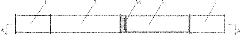
图1示出了本发明的超声速边界层风洞的整体上视结构示意图;Fig. 1 shows the overall top view structure schematic diagram of supersonic boundary layer wind tunnel of the present invention;
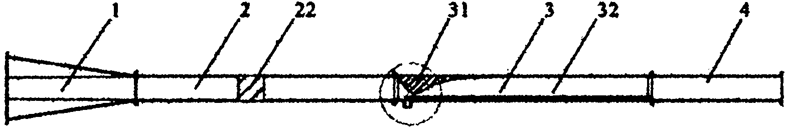
图2为图1中的超声速边界层风洞沿A-A位置的主视剖视结构示意图;以及Fig. 2 is a front view sectional structural schematic diagram of the supersonic boundary layer wind tunnel along A-A position in Fig. 1; and
图3为图2中B部的局部放大结构示意图。FIG. 3 is a schematic diagram of a partially enlarged structure of part B in FIG. 2 .
具体实施方式Detailed ways
以下结合附图对本发明的实施例进行详细说明,但是本发明可以由权利要求限定和覆盖的多种不同方式实施。The embodiments of the present invention will be described in detail below with reference to the accompanying drawings, but the present invention can be implemented in many different ways defined and covered by the claims.
参见图1,图2,根据本发明的一种超声速边界层风洞,包括:位于风洞最前端的过渡段1,用于引入气流(气流可以是空气流,根据实验目的、领域、要求等的不同,也可以采用其他气体),并对气流进行第一级整流,使进入其中的气流形成需要的流动形态(平流形态);稳定段2,连接在过渡段1的下游,用于对气流进行第二级整流,使进入其中的气流具有稳定的流动特性;喷管实验段3,连接在稳定段2的下游,包括:喷管部31,构造成单边膨胀喷管结构,对从稳定段2中流入的气流进行加速,使风洞实验部入口气流达到超声速状态;实验部32,位于所述喷管部的下游,用于对形成的超声速边界层流场的时空结构进行观测等实验研究,实验部32的周壁形成有透明窗口;以及边界层平板(例如光学玻璃材质的平板)33,设置在所述喷管实验段3的内腔中,从喷管部31延伸到实验部32中,用于与喷管部和实验部的周壁相配合,形成超声速边界层流场。Referring to Fig. 1, Fig. 2, according to a kind of supersonic boundary layer wind tunnel of the present invention, comprise: be positioned at the transition section 1 of front end of wind tunnel, be used for introducing airflow (airflow can be air flow, according to experimental purpose, field, requirement etc. different, other gases can also be used), and the first-stage rectification is performed on the airflow, so that the airflow entering it forms the required flow form (advection form); the stable section 2 is connected downstream of the transition section 1, and is used to adjust the airflow Carry out second stage rectification, make the air-flow that enters therein have stable flow characteristic; Nozzle test section 3, be connected in the downstream of stable section 2, comprise: Nozzle part 31, be constructed as the unilateral expansion nozzle structure, to from stable The airflow flowing in section 2 is accelerated to make the airflow at the inlet of the wind tunnel experiment section reach a supersonic state; the experiment section 32, located downstream of the nozzle section, is used to observe the space-time structure of the formed supersonic boundary layer flow field and other experiments Research, the peripheral wall of the experimental part 32 is formed with a transparent window; and the boundary layer flat plate (such as a flat plate of optical glass material) 33 is arranged in the inner cavity of the nozzle experimental section 3 and extends from the nozzle part 31 to the experimental part 32 In it, it is used to cooperate with the surrounding walls of the nozzle part and the experimental part to form a supersonic boundary layer flow field.
通过在风洞的喷管实验段3内腔中设置边界层平板33,并将喷管实验段3的喷管部31构造成单边膨胀喷管结构,从而在边界层平板33上可以生成所需的边界层。由于边界层平板33的表面纹理便于设置,通过改变边界层平板33的形状和/或表面纹理(包括整体区域或局部区域的表面纹理,例如粗糙度、是否有条纹或其他形状的表面图案、条纹或其他图案的延伸方向等)就可以实现边界层流态可控,以便于对超声速边界层的流场特性进行研究。By setting the
实验部3的周壁上的透明窗口至少要形成在实验部区域。优选地,可以在四个周壁均形成透明窗口,这样可以很方便地观察边界层流场形态。优选地,透明窗口的材料为光学玻璃,而且光学玻璃也可以设置在喷管部31的上下周壁和侧壁上,以便于进行光学非接触测试技术的实施。优选地,透明窗口向前延伸到边界层平板33的上游端所在区域,这样可以全面地观察和研究边界层流场的形成前后演变过程。在混合实验部32的下游还连接有扩压段4,具有沿朝向下游方向收缩的内腔结构。The transparent window on the peripheral wall of the experimental part 3 should be formed at least in the experimental part area. Preferably, transparent windows can be formed on the four surrounding walls, so that the shape of the boundary layer flow field can be observed conveniently. Preferably, the material of the transparent window is optical glass, and the optical glass can also be arranged on the upper and lower peripheral walls and side walls of the
进入过渡段1的气流经过稳定段2的稳定处理,然后送入喷管实验段3中,稳定的气流经过喷管部31进行加速,并在边界层平板33上形成超声速边界层,使整个喷管实验段内的流场满足边界层实验研究需要,在边界层平板33的下游气流入扩压段4中,扩压段4为收缩管道,起到扩压节能的作用,以提高风洞的启动性能。The airflow entering the transition section 1 is stabilized by the stabilization section 2, and then sent to the nozzle experiment section 3. The stable airflow is accelerated through the
边界层平板33优选为可拆卸地设置在喷管实验段3中,当为了满足不同实验需要而对边界层平板33的相关形状结构进行调整时,可以很方便地将已安装的边界层平板33拆除,并换装已经调整为所需结构的边界层平板33,从而可以实现对流体流动的控制,能够有效地提高实验效率,节约时间。另外,边界层平板优选采用光学玻璃制成,一是可以降低表面粗糙度,二是便于探测光线照明流场。The
本实施例中,超声速边界层风洞的过渡段1的横截面从上游端向下游端呈由圆形轮廓向矩形轮廓过渡的变化形态。入口处圆形轮廓可以方便地与外部送风设备的圆形出风口相连接。如果外部送风设备的出风口为矩形,则过渡段上游端只需要配置相应的矩形轮廓即可。过渡段1与稳定段2的连接端为矩形轮廓,能够实现与稳定段2的良好衔接。In this embodiment, the cross-section of the transition section 1 of the supersonic boundary layer wind tunnel changes from a circular profile to a rectangular profile from the upstream end to the downstream end. The circular profile of the inlet can be easily connected with the circular air outlet of the external air supply equipment. If the air outlet of the external air supply device is rectangular, the upstream end of the transition section only needs to be configured with a corresponding rectangular outline. The connecting end of the transition section 1 and the stabilizing section 2 has a rectangular profile, which can achieve a good connection with the stabilizing section 2 .
稳定段2的横截面呈矩形,包括相平行的上周壁和下周壁以及连接上周壁和下周壁的两个侧壁,可以对过渡段1中的气流进行调整,使从过渡段1进入的气体在其中稳定的流动。喷管实验段3的横截面呈矩形,包括上周壁和下周壁以及连接上周壁和下周壁的两个侧壁,上周壁和下周壁形成一体的连续喷管型面曲线,这样,单边膨胀喷管结构的一侧是连续喷管型面曲线,另一侧是可控的边界层平板表面,因而整个喷管壁面曲率连续,有利于全流场消波。The cross section of the stable section 2 is rectangular, including the parallel upper and lower peripheral walls and two side walls connecting the upper and lower peripheral walls. The gas flows in it stably. The cross-section of the nozzle test section 3 is rectangular, including the upper wall and the lower wall and two side walls connecting the upper wall and the lower wall, and the upper wall and the lower wall form an integral continuous nozzle profile curve, like this, One side of the unilateral expansion nozzle structure is a continuous nozzle profile curve, and the other side is a controllable boundary layer flat surface, so the curvature of the entire nozzle wall is continuous, which is conducive to wave elimination in the entire flow field.
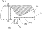
如图3所示,根据本发明的超声速边界层风洞的实施例,边界层平板23通过支撑件332设置在喷管实验段3中,并位于下周壁上方预定高度处。支撑件332设置在边界层平板23的前端,起到支撑边界层平板23并使其处于预定高度的作用。由于边界层平板23悬空设置在喷管实验段3的内腔中,从喷管部31延伸到所述实验部32中,这样,边界层仅由边界层平板来决定,可以尽可能地避免下周壁内表面对生成气流的流场的影响。在边界层平板23的上侧形成一个上腔301,下侧形成一个下腔302。优选地,本实施例中边界层平板23的上游端延伸经过所述喷管部31的喉部而进入亚声速区域303中,喷管平面壁在亚声速段内根据该段地流线形状,略向上弯。边界层平板23的上游端适应于该处对应的喷管型面曲线的流线形状而形成向上弯曲的导流带331,有利于避免前缘边界层出现分离泡,可以更有利于实现可控制的流场流态,边界层流场品质好,二维特性好。导流带331具有呈弧面或平面状向上游外侧倾斜的过渡表面及位于上游端的尖端边缘,当气流从稳定段2进入喷管实验段3中时,进一步改善了导流特性,有利于避免传统平板边界层中,平板前缘激波反射带来的干扰。As shown in FIG. 3 , according to the embodiment of the supersonic boundary layer wind tunnel of the present invention, the boundary layer plate 23 is set in the nozzle test section 3 through the
作为对本发明实施例的一个重要改进(这是本发明的关键技术之一),喷管实验段3的下周壁上设置有边界层抽吸出口34,边界层抽吸出口34设置在与喷管部31的喉部对应的位置,通过喉部抽吸以及气流在该处的收缩加速,可以尽可能地降低上游来流边界层的影响。作为更进一步的改进,边界层抽吸出口34向前延伸到喷管部31的喉部中与导流部331对应的位置(已过了喉部中通道最窄的位置到了亚声速区域),可以使气流在进入导流部331时获得更好的加速效果,更重要的是,还可以更好地减少上游来流边界层的影响。As an important improvement to the embodiment of the present invention (this is one of the key technologies of the present invention), the lower peripheral wall of the nozzle test section 3 is provided with a boundary layer suction outlet 34, and the boundary layer suction outlet 34 is arranged on the nozzle pipe. The position corresponding to the throat of
在本实施例中,喷管实验段3的宽高比(系指喷管实验段中通道的宽高比,可以按照左右侧壁之间的距离与上下周壁之间的距离之比来计算)大于4,优选地,其宽高比大于5,由此所形成的喷管实验段3,可以有效地消除左右连接侧壁的边界层对平板边界层流场的影响,以获得理想的流场流态。In this embodiment, the aspect ratio of the nozzle test section 3 (referring to the aspect ratio of the channel in the nozzle test section, can be calculated according to the ratio of the distance between the left and right side walls and the distance between the upper and lower peripheral walls) greater than 4, preferably, its aspect ratio is greater than 5, the nozzle test section 3 thus formed can effectively eliminate the influence of the boundary layer connecting the left and right side walls on the flow field of the flat plate boundary layer, so as to obtain an ideal flow field fluid state.
为了使稳定段2中的气流具有较好的稳定流动效果,在稳定段2的下游设置有整流装置22,整流装置22包括蜂窝器和沙网。蜂窝器可有效的抑制来流的横向脉动,沙网可使大尺度旋涡碎裂为小尺度旋涡。整流装置22的存在,可以使流入稳定端2内的气流更加平稳,降低了湍流度,使气流能够获得更加稳定的流动性能,可以使进入喷管实验段3内的流动气体所受到的干扰降到最小,使实验取得较为准确的效果。In order to make the airflow in the stabilizing section 2 have a better effect of stabilizing the flow, a rectifying
本实施例中的喷管部31和实验段32整体加工构成喷管实验段3,为二维构型,可通过调整喷管部31长度控制流态为层流或湍流。In this embodiment, the
由上述描述可知,根据本发明的超声速边界层风洞,通过改变边界层平板的形状和表面纹理(包括表面粗糙度和纹理形态等)实现边界层流态可控,便于对超声速边界层层的流场特性进行研究,可以有效地消除左右连接侧壁边界层对平板边界层流场的影响,以获得理想的流场流态,通过在实验部32四周均设置光学玻璃构成的周壁,使其便于实施光学非接触测试技术,便于观察边界层流场形态。As can be seen from the above description, according to the supersonic boundary layer wind tunnel of the present invention, the boundary layer flow state can be controlled by changing the shape and surface texture (including surface roughness and texture morphology, etc.) The study of the flow field characteristics can effectively eliminate the influence of the left and right connecting side wall boundary layers on the flow field of the flat plate boundary layer, so as to obtain an ideal flow field flow state. By setting the surrounding walls made of optical glass around the
以上所述仅为本发明的优选实施例而已,并不用于限制本发明,对于本领域的技术人员来说,本发明可以有各种更改和变化。凡在本发明的精神和原则之内,所作的任何修改、等同替换、改进等,均应包含在本发明的保护范围之内。The above descriptions are only preferred embodiments of the present invention, and are not intended to limit the present invention. For those skilled in the art, the present invention may have various modifications and changes. Any modifications, equivalent replacements, improvements, etc. made within the spirit and principles of the present invention shall be included within the protection scope of the present invention.
Claims (18)
Priority Applications (1)
| Application Number | Priority Date | Filing Date | Title |
|---|---|---|---|
| CN2010105512826A CN102012307B (en) | 2010-11-18 | 2010-11-18 | supersonic boundary layer wind tunnel |
Applications Claiming Priority (1)
| Application Number | Priority Date | Filing Date | Title |
|---|---|---|---|
| CN2010105512826A CN102012307B (en) | 2010-11-18 | 2010-11-18 | supersonic boundary layer wind tunnel |
Publications (2)
| Publication Number | Publication Date |
|---|---|
| CN102012307A true CN102012307A (en) | 2011-04-13 |
| CN102012307B CN102012307B (en) | 2012-03-28 |
Family
ID=43842554
Family Applications (1)
| Application Number | Title | Priority Date | Filing Date |
|---|---|---|---|
| CN2010105512826A Expired - Fee Related CN102012307B (en) | 2010-11-18 | 2010-11-18 | supersonic boundary layer wind tunnel |
Country Status (1)
| Country | Link |
|---|---|
| CN (1) | CN102012307B (en) |
Cited By (14)
| Publication number | Priority date | Publication date | Assignee | Title |
|---|---|---|---|---|
| CN102840960A (en) * | 2012-08-30 | 2012-12-26 | 华南理工大学 | Method for equalizing wind field of wind tunnel by using Rafah tube |
| CN103234941A (en) * | 2013-04-17 | 2013-08-07 | 中国工程物理研究院流体物理研究所 | Dynamic measurement device and method of material laser reflectivity under subsonic tangential airflow |
| CN103954424A (en) * | 2014-04-30 | 2014-07-30 | 北京大学 | Method for expanding silent test area of hypersonic-velocity silent spray pipe and hypersonic-velocity spray pipe |
| CN104280205A (en) * | 2014-10-24 | 2015-01-14 | 中国人民解放军国防科学技术大学 | Supersonic velocity laminar flow spraying pipe and supersonic velocity quiet wind tunnel thereof |
| CN104359646B (en) * | 2014-10-17 | 2016-09-14 | 北京航天益森风洞工程技术有限公司 | Suction method is used to control the hypersonic nozzle of boundary layer thickness |
| CN106354903A (en) * | 2016-08-18 | 2017-01-25 | 中国人民解放军国防科学技术大学 | Determination method of the computational domain outer boundary for solving the steady circumfluence value of flying objects |
| CN107870076A (en) * | 2016-09-27 | 2018-04-03 | 中国空气动力研究与发展中心高速空气动力研究所 | A kind of variable boundary thickness degree experimental provision and its application method suitable for Cavity Flow wind- tunnel investigation |
| CN107869498A (en) * | 2016-09-26 | 2018-04-03 | 中国空气动力研究与发展中心高速空气动力研究所 | A kind of supersonic speed Cavity Flow control method based on disturbed motion shock wave |
| CN108168831A (en) * | 2017-12-15 | 2018-06-15 | 中国航空工业集团公司沈阳空气动力研究所 | A kind of continuous change Mach number experiment supersonic wind tunnel |
| CN108303227A (en) * | 2018-02-14 | 2018-07-20 | 中国空气动力研究与发展中心高速空气动力研究所 | Aeroelastic effect wind tunnel test half model system and test method |
| CN109827743A (en) * | 2019-04-02 | 2019-05-31 | 重庆科技学院 | A kind of multiple spot multistage adjusting flow-disturbing wedge |
| CN110009979A (en) * | 2019-05-07 | 2019-07-12 | 中国人民解放军国防科技大学 | Laval Nozzle Demonstration Device and System |
| CN115248103A (en) * | 2022-06-22 | 2022-10-28 | 中国人民解放军国防科技大学 | Internal flow channel wind tunnel with boundary layer suction and back pressure controllable |
| CN116499686A (en) * | 2023-06-29 | 2023-07-28 | 中国航空工业集团公司沈阳空气动力研究所 | Ground high-speed ejection simulation system and simulation method for wind tunnel test |
Families Citing this family (1)
| Publication number | Priority date | Publication date | Assignee | Title |
|---|---|---|---|---|
| CN108240898A (en) * | 2016-12-23 | 2018-07-03 | 中国航空工业集团公司沈阳空气动力研究所 | A kind of impulse type wind-tunnel tandem jet pipe |
Citations (2)
| Publication number | Priority date | Publication date | Assignee | Title |
|---|---|---|---|---|
| US5713212A (en) * | 1997-02-07 | 1998-02-03 | Mcdonnell Douglas Corporation | Apparatus and method for generating air stream |
| WO2000071956A1 (en) * | 1999-05-21 | 2000-11-30 | Aero Systems Engineering, Inc. | Wind tunnel and heat exchanger therefor |
-
2010
- 2010-11-18 CN CN2010105512826A patent/CN102012307B/en not_active Expired - Fee Related
Patent Citations (2)
| Publication number | Priority date | Publication date | Assignee | Title |
|---|---|---|---|---|
| US5713212A (en) * | 1997-02-07 | 1998-02-03 | Mcdonnell Douglas Corporation | Apparatus and method for generating air stream |
| WO2000071956A1 (en) * | 1999-05-21 | 2000-11-30 | Aero Systems Engineering, Inc. | Wind tunnel and heat exchanger therefor |
Non-Patent Citations (2)
| Title |
|---|
| 《中国博士学位论文全文数据库》 20090715 赵玉新 超声速混合层时空结构的实验研究 全文 1-18 , 第07期 2 * |
| 《西安建筑科技大学学报》 19970930 王元等 风工程学与大气边界层风洞 第344-348页 1-18 第29卷, 第3期 2 * |
Cited By (21)
| Publication number | Priority date | Publication date | Assignee | Title |
|---|---|---|---|---|
| CN102840960A (en) * | 2012-08-30 | 2012-12-26 | 华南理工大学 | Method for equalizing wind field of wind tunnel by using Rafah tube |
| CN102840960B (en) * | 2012-08-30 | 2015-07-01 | 华南理工大学 | Method for equalizing wind field of wind tunnel by using Rafah tube |
| CN103234941A (en) * | 2013-04-17 | 2013-08-07 | 中国工程物理研究院流体物理研究所 | Dynamic measurement device and method of material laser reflectivity under subsonic tangential airflow |
| CN103234941B (en) * | 2013-04-17 | 2015-09-16 | 中国工程物理研究院流体物理研究所 | Material laser reflectivity dynamic measurement device and method under subsonic speed tangential gas flow |
| CN103954424A (en) * | 2014-04-30 | 2014-07-30 | 北京大学 | Method for expanding silent test area of hypersonic-velocity silent spray pipe and hypersonic-velocity spray pipe |
| CN103954424B (en) * | 2014-04-30 | 2016-05-04 | 北京大学 | Expand method and the hypersonic nozzle in hypersonic quiet jet pipe static test district |
| CN104359646B (en) * | 2014-10-17 | 2016-09-14 | 北京航天益森风洞工程技术有限公司 | Suction method is used to control the hypersonic nozzle of boundary layer thickness |
| CN104280205A (en) * | 2014-10-24 | 2015-01-14 | 中国人民解放军国防科学技术大学 | Supersonic velocity laminar flow spraying pipe and supersonic velocity quiet wind tunnel thereof |
| CN106354903A (en) * | 2016-08-18 | 2017-01-25 | 中国人民解放军国防科学技术大学 | Determination method of the computational domain outer boundary for solving the steady circumfluence value of flying objects |
| CN106354903B (en) * | 2016-08-18 | 2019-04-26 | 中国人民解放军国防科学技术大学 | A method for determining outer boundary of computational domain for numerical solution of steady flow around aircraft |
| CN107869498A (en) * | 2016-09-26 | 2018-04-03 | 中国空气动力研究与发展中心高速空气动力研究所 | A kind of supersonic speed Cavity Flow control method based on disturbed motion shock wave |
| CN107869498B (en) * | 2016-09-26 | 2019-04-16 | 中国空气动力研究与发展中心高速空气动力研究所 | A kind of supersonic speed Cavity Flow control method based on disturbed motion shock wave |
| CN107870076A (en) * | 2016-09-27 | 2018-04-03 | 中国空气动力研究与发展中心高速空气动力研究所 | A kind of variable boundary thickness degree experimental provision and its application method suitable for Cavity Flow wind- tunnel investigation |
| CN108168831A (en) * | 2017-12-15 | 2018-06-15 | 中国航空工业集团公司沈阳空气动力研究所 | A kind of continuous change Mach number experiment supersonic wind tunnel |
| CN108303227A (en) * | 2018-02-14 | 2018-07-20 | 中国空气动力研究与发展中心高速空气动力研究所 | Aeroelastic effect wind tunnel test half model system and test method |
| CN108303227B (en) * | 2018-02-14 | 2024-04-05 | 中国空气动力研究与发展中心高速空气动力研究所 | Static aeroelastic wind tunnel test semi-model system and test method |
| CN109827743A (en) * | 2019-04-02 | 2019-05-31 | 重庆科技学院 | A kind of multiple spot multistage adjusting flow-disturbing wedge |
| CN110009979A (en) * | 2019-05-07 | 2019-07-12 | 中国人民解放军国防科技大学 | Laval Nozzle Demonstration Device and System |
| CN115248103A (en) * | 2022-06-22 | 2022-10-28 | 中国人民解放军国防科技大学 | Internal flow channel wind tunnel with boundary layer suction and back pressure controllable |
| CN116499686A (en) * | 2023-06-29 | 2023-07-28 | 中国航空工业集团公司沈阳空气动力研究所 | Ground high-speed ejection simulation system and simulation method for wind tunnel test |
| CN116499686B (en) * | 2023-06-29 | 2023-08-22 | 中国航空工业集团公司沈阳空气动力研究所 | Ground high-speed ejection simulation system and simulation method for wind tunnel test |
Also Published As
| Publication number | Publication date |
|---|---|
| CN102012307B (en) | 2012-03-28 |
Similar Documents
| Publication | Publication Date | Title |
|---|---|---|
| CN102012307A (en) | Supersonic speed boundary layer wind tunnel | |
| CN102023078B (en) | Supersonic Planar Mixed Layer Wind Tunnel | |
| CN101975652B (en) | Ultrasonic-velocity free vortex wind tunnel | |
| CN102023077B (en) | Supersonic Axisymmetric Boundary Layer Wind Tunnel | |
| CN101975653B (en) | Supersonic-speed axisymmetric mixing layer wind tunnel | |
| CN102023079B (en) | Supersonic free vortex mixing layer wind tunnel | |
| CN102998085B (en) | Mixing jet tube runner wall defining method, mixing jet tube and mixed supersonic wind-tunnel | |
| CN110160734B (en) | Wind tunnel spray pipe based on porous medium, active noise reduction device and method | |
| CN104280205A (en) | Supersonic velocity laminar flow spraying pipe and supersonic velocity quiet wind tunnel thereof | |
| Dong et al. | Flow past a trapezoidal tab | |
| CN103678774B (en) | Designing method for supersonic velocity thrust exhaust nozzle considering inlet parameter unevenness | |
| CN101813027A (en) | Bump air inlet method for realizing integration of unequal-strength wave system with forebody | |
| CN104908957B (en) | Ridge type scans vortex generator and generation method | |
| CN103939216A (en) | Embedded type air inlet channel using combined opening surface vortex control method | |
| Xu et al. | Experimental and numerical investigations on the unsteady flow and film cooling characteristics of the trailing edge cutback | |
| CN211650472U (en) | Air deflector assembly, air conditioner indoor unit and air conditioner | |
| CN106596038A (en) | Calculating method of supersonic-speed and hypersonic-speed mute wind tunnel spray pipe suction flow | |
| Li et al. | Numerical and experimental research on the outlet flow field for the air multiplier | |
| Clement et al. | Characteristics of sonic jets with tabs | |
| Lengani et al. | Application of a synthetic jet to control boundary layer separation under ultra-high-lift turbine pressure distribution | |
| Zeng et al. | Experimental Study on Controlling Flow Separation of Compressor Cascades With Self-Excited Sweeping Jet Actuator | |
| Isaev et al. | Flow control of the semicircular airfoil with a vortex cell at slot suction of air and its blowout into the near wake | |
| CN108267295B (en) | A flow control nozzle | |
| CN211650682U (en) | Air deflector assembly and air conditioner | |
| CN211476252U (en) | Air deflector assembly and air conditioner |
Legal Events
| Date | Code | Title | Description |
|---|---|---|---|
| C06 | Publication | ||
| PB01 | Publication | ||
| C10 | Entry into substantive examination | ||
| SE01 | Entry into force of request for substantive examination | ||
| C14 | Grant of patent or utility model | ||
| GR01 | Patent grant | ||
| CF01 | Termination of patent right due to non-payment of annual fee |
Granted publication date: 20120328 |
|
| CF01 | Termination of patent right due to non-payment of annual fee |