CN102024923B - Fixing structure - Google Patents
Fixing structure Download PDFInfo
- Publication number
- CN102024923B CN102024923B CN200910306969.0A CN200910306969A CN102024923B CN 102024923 B CN102024923 B CN 102024923B CN 200910306969 A CN200910306969 A CN 200910306969A CN 102024923 B CN102024923 B CN 102024923B
- Authority
- CN
- China
- Prior art keywords
- engaging
- fixed
- introduction part
- protrusion
- fixed structure
- Prior art date
- Legal status (The legal status is an assumption and is not a legal conclusion. Google has not performed a legal analysis and makes no representation as to the accuracy of the status listed.)
- Expired - Fee Related
Links
Images


Classifications
-
- H—ELECTRICITY
- H01—ELECTRIC ELEMENTS
- H01M—PROCESSES OR MEANS, e.g. BATTERIES, FOR THE DIRECT CONVERSION OF CHEMICAL ENERGY INTO ELECTRICAL ENERGY
- H01M50/00—Constructional details or processes of manufacture of the non-active parts of electrochemical cells other than fuel cells, e.g. hybrid cells
- H01M50/20—Mountings; Secondary casings or frames; Racks, modules or packs; Suspension devices; Shock absorbers; Transport or carrying devices; Holders
- H01M50/204—Racks, modules or packs for multiple batteries or multiple cells
- H01M50/207—Racks, modules or packs for multiple batteries or multiple cells characterised by their shape
- H01M50/213—Racks, modules or packs for multiple batteries or multiple cells characterised by their shape adapted for cells having curved cross-section, e.g. round or elliptic
-
- H—ELECTRICITY
- H01—ELECTRIC ELEMENTS
- H01M—PROCESSES OR MEANS, e.g. BATTERIES, FOR THE DIRECT CONVERSION OF CHEMICAL ENERGY INTO ELECTRICAL ENERGY
- H01M50/00—Constructional details or processes of manufacture of the non-active parts of electrochemical cells other than fuel cells, e.g. hybrid cells
- H01M50/20—Mountings; Secondary casings or frames; Racks, modules or packs; Suspension devices; Shock absorbers; Transport or carrying devices; Holders
- H01M50/204—Racks, modules or packs for multiple batteries or multiple cells
- H01M50/207—Racks, modules or packs for multiple batteries or multiple cells characterised by their shape
- H01M50/216—Racks, modules or packs for multiple batteries or multiple cells characterised by their shape adapted for button or coin cells
-
- Y—GENERAL TAGGING OF NEW TECHNOLOGICAL DEVELOPMENTS; GENERAL TAGGING OF CROSS-SECTIONAL TECHNOLOGIES SPANNING OVER SEVERAL SECTIONS OF THE IPC; TECHNICAL SUBJECTS COVERED BY FORMER USPC CROSS-REFERENCE ART COLLECTIONS [XRACs] AND DIGESTS
- Y02—TECHNOLOGIES OR APPLICATIONS FOR MITIGATION OR ADAPTATION AGAINST CLIMATE CHANGE
- Y02E—REDUCTION OF GREENHOUSE GAS [GHG] EMISSIONS, RELATED TO ENERGY GENERATION, TRANSMISSION OR DISTRIBUTION
- Y02E60/00—Enabling technologies; Technologies with a potential or indirect contribution to GHG emissions mitigation
- Y02E60/10—Energy storage using batteries
Landscapes
- Chemical & Material Sciences (AREA)
- Chemical Kinetics & Catalysis (AREA)
- Electrochemistry (AREA)
- General Chemical & Material Sciences (AREA)
- Battery Mounting, Suspending (AREA)
Abstract
一种固定结构,其包括筒体、设于筒体开口端的固定盖及固定于固定盖上的卡合件,卡合件上设有卡持凸起及与卡持凸起相邻近的限位凸起,筒体的内壁上靠近开口端处设有限位部、导入部及与该导入部相连通的卡合部,限位部设置在靠近导入部的边缘位置,卡合部为沿筒体内壁的周向延伸的环形卡合槽,卡持凸起能够从导入部滑动至该卡合部,限位凸起能够沿导入部滑动,卡合件在该筒体内可转动,使卡持凸起沿该卡合部滑动且可分离地与卡合部卡持,当该卡持凸起与该卡合部卡持时,限位凸起与限位部相配合,以限制卡合件转动。上述固定结构固定或拆卸电池较方便且结构简单。
A fixed structure, which includes a cylinder body, a fixed cover arranged at the opening end of the cylinder body, and an engaging piece fixed on the fixed cover. The engaging piece is provided with a locking protrusion and a limiter adjacent to the locking protrusion. position protrusion, the inner wall of the cylinder near the opening end is provided with a limit part, an introduction part and a locking part connected with the introduction part, the limit part is set at the edge position close to the introduction part, and the locking part is along the cylinder The circumferentially extending annular engaging groove of the inner wall, the engaging protrusion can slide from the introduction part to the engaging part, the position-limiting protrusion can slide along the introducing part, and the engaging part can rotate in the cylinder, so that the engaging part The protrusion slides along the engaging part and is detachably engaged with the engaging part. When the engaging protrusion is engaged with the engaging part, the limiting protrusion cooperates with the limiting part to limit the engaging part. turn. The above-mentioned fixing structure is more convenient to fix or remove the battery and has a simple structure.
Description
技术领域technical field
本发明涉及一种固定结构,特别涉及一种电池固定结构。The invention relates to a fixing structure, in particular to a battery fixing structure.
背景技术Background technique
一些常用的电子装置,如无线键盘、无线触摸板、遥控器等,需要电池为其供电。这些电子装置通常采用固定结构将电池固定。Some commonly used electronic devices, such as wireless keyboards, wireless touch panels, remote controls, etc., require batteries to power them. These electronic devices usually use a fixed structure to fix the battery.
一种固定结构,其用于将电池固定于电子装置内,该固定结构包括筒体及将电池固定于该筒体内的固定盖。筒体内壁上形成有第一螺纹,固定盖大致为圆柱状,其外表面形成有与第一螺纹相螺合的第二螺纹。固定电池时,先将电池装入筒体内,再将固定盖装入筒体并通过其上的第二螺纹与筒体上的第一螺纹螺合以固定电池于筒体内。A fixing structure is used for fixing a battery in an electronic device. The fixing structure includes a barrel and a fixing cover for fixing the battery in the barrel. A first thread is formed on the inner wall of the barrel, and the fixed cover is roughly cylindrical, and a second thread which is screwed with the first thread is formed on the outer surface of the fixed cover. When fixing the battery, first put the battery into the barrel, then put the fixing cover into the barrel and screw the second thread on it with the first thread on the barrel to fix the battery in the barrel.
上述固定结构利用筒体上的第一螺纹与固定盖上的第二螺纹配合而固定电池,其固定或拆卸电池较为繁琐。The above-mentioned fixing structure fixes the battery by cooperating with the first screw thread on the barrel body and the second screw thread on the fixing cover, and the fixing or dismounting of the battery is cumbersome.
发明内容Contents of the invention
鉴于上述状况,有必要提供一种固定或拆卸电池较方便的固定结构。In view of the above situation, it is necessary to provide a fixing structure which is more convenient for fixing or removing the battery.
一种固定结构,其包括筒体、设于筒体开口端的固定盖及固定于固定盖上的卡合件,卡合件上设有卡持凸起及与卡持凸起相邻近的限位凸起,筒体的内壁上靠近开口端处设有限位部、导入部及与导入部相连通的卡合部,限位部设置在靠近导入部的边缘位置,卡合部为沿筒体内壁的周向延伸的环形卡合槽,且位于限位部远离该筒体开口端的一侧,卡持凸起能够从导入部滑动至卡合部,限位凸起能够沿导入部滑动,卡合件在该筒体内可转动,使卡持凸起沿该卡合部滑动且可分离地与卡合部卡持,当该卡持凸起与该卡合部卡持时,限位凸起与限位部相配合,以限制卡合件转动。A fixed structure, which includes a cylinder body, a fixed cover arranged at the opening end of the cylinder body, and an engaging piece fixed on the fixed cover. The engaging piece is provided with a clamping protrusion and a limiter adjacent to the clamping protrusion. The position is raised, and the inner wall of the cylinder near the opening end is provided with a limit part, an introduction part and a locking part connected with the introduction part. The circumferentially extending annular engaging groove of the wall is located on the side of the limiting portion away from the opening end of the cylinder, the locking protrusion can slide from the introducing portion to the engaging portion, the limiting protrusion can slide along the introducing portion, and the engaging The fitting is rotatable in the barrel, so that the holding protrusion slides along the engaging portion and is detachably engaged with the engaging portion. When the engaging protrusion is engaged with the engaging portion, the position-limiting protrusion Cooperate with the limiting part to limit the rotation of the engaging part.
上述固定结构通过卡合件的卡持凸起与筒体的卡合部可分离地卡持,并且利用卡合件的限位凸起与筒体的限位部相配合,以限制卡合件转动,从而将电池固定于筒体内,其结构简单且固定或拆卸电池较方便。The above-mentioned fixing structure is detachably held by the clamping protrusion of the engaging part and the engaging part of the cylinder, and the limiting protrusion of the engaging part cooperates with the limiting part of the cylinder to limit the clamping part. Rotate to fix the battery in the barrel, the structure is simple and it is more convenient to fix or disassemble the battery.
附图说明Description of drawings
图1是本发明实施方式的固定结构的部分立体图。Fig. 1 is a partial perspective view of a fixing structure according to an embodiment of the present invention.
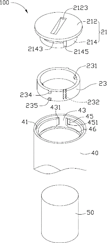
图2是图1所示的固定结构的立体分解图。FIG. 2 is an exploded perspective view of the fixing structure shown in FIG. 1 .
图3是图1沿III-III方向的剖面示意图。Fig. 3 is a schematic cross-sectional view along III-III direction of Fig. 1 .
图4是图1沿IV-IV方向的剖面示意图。FIG. 4 is a schematic cross-sectional view along IV-IV direction of FIG. 1 .
具体实施方式Detailed ways
下面结合附图及实施方式对本发明的固定结构作进一步详细说明。The fixing structure of the present invention will be described in further detail below in conjunction with the accompanying drawings and embodiments.
请参阅图1及图2,本发明较佳实施方式的固定结构100包括筒体40、固定于筒体40开口端的固定盖21及固定于固定盖21上的卡合件23。电池50可容置于筒体40内,且与固定盖21相抵持。卡合件23与筒体40相卡合,从而将固定盖21固定于筒体40上。固定结构100可应用于无线键盘、无线触摸板、遥控器等电子装置。Please refer to FIG. 1 and FIG. 2 , a
固定盖21包括圆形的盖体212及设于盖体212一侧的圆柱形的固定部214。盖体212的直径略大于固定部214的直径,以致于盖体212被抵挡于筒体40外。为方便装配操作,盖体212上沿其径向还开设有“一”字形的操作槽2123,可用螺丝刀等工具(图未示)卡持该操作槽2123,以将固定盖21装配在筒体40一端。固定部214的侧壁上开设有两个的卡合槽2143及一个连通其中一个卡合槽214的导向槽2145。两个卡合槽2143相对于固定部214的中心轴对称设置,且其延伸方向平行于盖体212所在的平面。导向槽2145沿平行于固定部214的中心轴的方向延伸。固定盖21可由导电金属材料制成。The
卡合件23大致呈圆环状,其包括两个弹性卡钩231、一个导向凸起232、两个限位凸起234及两个卡持凸起235。两个弹性卡钩231间隔地设置于卡合件23的内侧壁上靠近其端部的位置。两个弹性卡钩231可分别卡设于固定盖21的两个卡合槽2143内。导向凸起232设于卡合件23内侧壁上,且可在固定盖21的导向槽2145滑动。两个限位凸起234相对于卡合件23的中心轴对称地设于卡合件23的外侧壁上靠近其一端的位置。两个卡持凸起235设于卡合件23外侧壁上靠近另一端的位置。每个卡持凸起235对应一个限位凸起234。相邻的卡持凸起235和限位凸起234沿平行于卡合件23的中心轴的方向排列。卡合件23可由弹性塑料制成。The
筒体40的内壁上设有一个环形台阶部41、两个导入部43、两个限位部45及一个卡合部46。台阶部41位于筒体40的开口端,且沿筒体40内壁的周向延伸。固定盖21的盖体212被台阶部41所抵挡。限位部45设于筒体40的内壁上靠近导入部43的边缘的位置。卡合部46设于筒体40的内壁上,且位于限位部45远离筒体40开口端的一侧。导入部43设于成于筒体40的内壁上,且与卡合部46及台阶部41相贯通。卡合件23的限位凸起234可从导入部43滑动至限位部45,且与限位部45相配合。卡合件23的卡持凸起234可从导入部43滑动至卡合部46,且可与卡合部46相卡持。具体在本实施方式中,导入部43为平行于筒体40的中心轴的方向延伸的导入槽,且其具有两个弧形侧壁431,以便于卡合件23的卡持凸起235从导入部43滑入限位部45内;限位部45为平行于筒体40的中心轴的方向延伸的限位槽,其具有基本垂直于底部的侧壁451,侧壁451可限制该限位凸起沿平行于该筒体的中心轴的方向向该筒体内部滑动;卡合部46为沿筒体40内壁的周向延伸的卡合槽。An annular
请同时参阅图2及图3,组装固定盖21时,首先,将卡合件23的导向凸起232对应于固定盖21的导向槽2145。然后,用力推动卡合件23,使卡合件23的导向凸起232在固定盖21的导向槽2145内滑动,直至卡合件23的弹性卡钩231卡合于固定盖21的卡合槽2143内。最终,将卡合件23固定于固定盖21上。Please refer to FIG. 2 and FIG. 3 at the same time. When assembling the
请同时参阅图2及图4,固定结构100固定电池50时,首先,将电池50装入筒体40内。然后,将固定盖21的卡合件23的两个限位凸起234及两个卡持凸起235对应滑入筒体40的导入部43中。最后,旋转固定盖21,卡合件23的卡持凸起235卡持于筒体40的卡合部46内,直至卡合件23的限位凸起234滑入限位部45内,最终将电池50固定于筒体40内。Please refer to FIG. 2 and FIG. 4 at the same time. When the
拆卸电池50时,首先,反向旋转固定盖21,卡合件23的限位凸起235从筒体40的限位部45滑入导入部43内,同时,卡合件23的卡持凸起235对应于导入部43。接着,取出固定盖21,使卡合件23的限位凸起234及卡持凸起235脱离筒体40的导入部43。最后,从筒体40内取出电池50。When dismounting the
上述固定结构100通过固定盖21的卡持凸起235与筒体40的卡合部46可分离地卡持,并利用固定盖21的限位凸起234与筒体40的限位部45相配合,以限制固定盖21转动,从而将电池50固定于筒体40内,其结构简单且固定或拆卸电池较方便。另外,卡合件23采用弹性塑料制成,其可避免固定盖21与筒体40硬性摩擦,从而提高固定结构100的使用寿命。The above-mentioned
可以理解,卡合件23与固定盖21不限于利用弹性卡钩231与卡合槽2143相配合,而将卡合件23固定于固定盖21上,其也可利用其它方式,例如,卡合件23与固定盖21一体成型,或者采用胶水将卡合件23固定于固定盖21上。筒体40的导入部43不限于为平行于筒体40的中心轴的方向延伸的导入槽,其也可为平行于筒体40的中心轴的方向延伸的肋条。筒体40的限位部45不限于为平行于筒体40的中心轴的方向延伸的限位槽,其也可为“ㄈ”型卡合肋条;筒体40的卡合部46不限于为沿筒体40的内壁的周向延伸的卡合槽,其也可为沿筒体40的内壁的周向延伸凸缘。It can be understood that the engaging
另外,本领域技术人员还可在本发明精神内做其它变化,当然,这些依据本发明精神所做的变化,都应包含在本发明所要求保护的范围内。In addition, those skilled in the art can also make other changes within the spirit of the present invention. Of course, these changes made according to the spirit of the present invention should be included in the scope of protection claimed by the present invention.
Claims (9)
Priority Applications (2)
| Application Number | Priority Date | Filing Date | Title |
|---|---|---|---|
| CN200910306969.0A CN102024923B (en) | 2009-09-14 | 2009-09-14 | Fixing structure |
| US12/607,228 US20110064982A1 (en) | 2009-09-14 | 2009-10-28 | Fixing mechanism |
Applications Claiming Priority (1)
| Application Number | Priority Date | Filing Date | Title |
|---|---|---|---|
| CN200910306969.0A CN102024923B (en) | 2009-09-14 | 2009-09-14 | Fixing structure |
Publications (2)
| Publication Number | Publication Date |
|---|---|
| CN102024923A CN102024923A (en) | 2011-04-20 |
| CN102024923B true CN102024923B (en) | 2014-02-26 |
Family
ID=43730886
Family Applications (1)
| Application Number | Title | Priority Date | Filing Date |
|---|---|---|---|
| CN200910306969.0A Expired - Fee Related CN102024923B (en) | 2009-09-14 | 2009-09-14 | Fixing structure |
Country Status (2)
| Country | Link |
|---|---|
| US (1) | US20110064982A1 (en) |
| CN (1) | CN102024923B (en) |
Families Citing this family (5)
| Publication number | Priority date | Publication date | Assignee | Title |
|---|---|---|---|---|
| CN102044643B (en) * | 2009-10-19 | 2013-11-06 | 鸿富锦精密工业(深圳)有限公司 | Fixing structure |
| US9901115B2 (en) * | 2013-08-30 | 2018-02-27 | Huizhou Kimree Technology Co., Ltd. Shenzhen Branch | Battery component and electronic cigarette |
| CN104681760B (en) * | 2015-02-12 | 2017-05-10 | 实联长宜淮安科技有限公司 | Fixing device for internal structure winding body of lithium ion power battery |
| CA2997725C (en) * | 2017-03-10 | 2021-08-03 | Evolution Engineering Inc. | Battery coil engaging members for downhole tools |
| CN112265752A (en) * | 2020-11-03 | 2021-01-26 | 上海鸿研物流技术有限公司 | Lining bag and filling opening assembly thereof |
Citations (3)
| Publication number | Priority date | Publication date | Assignee | Title |
|---|---|---|---|---|
| US1676945A (en) * | 1928-07-10 | Laurence victor ellis | ||
| US2385624A (en) * | 1944-05-22 | 1945-09-25 | George R Godber | Closure means for container filling openings |
| US20070003825A1 (en) * | 2005-07-01 | 2007-01-04 | Perimeter Technologies Incorporated | Battery pack assembly |
Family Cites Families (1)
| Publication number | Priority date | Publication date | Assignee | Title |
|---|---|---|---|---|
| US2427914A (en) * | 1943-08-21 | 1947-09-23 | Bright Star Battery Company | Flashlight battery with plastic casing |
-
2009
- 2009-09-14 CN CN200910306969.0A patent/CN102024923B/en not_active Expired - Fee Related
- 2009-10-28 US US12/607,228 patent/US20110064982A1/en not_active Abandoned
Patent Citations (3)
| Publication number | Priority date | Publication date | Assignee | Title |
|---|---|---|---|---|
| US1676945A (en) * | 1928-07-10 | Laurence victor ellis | ||
| US2385624A (en) * | 1944-05-22 | 1945-09-25 | George R Godber | Closure means for container filling openings |
| US20070003825A1 (en) * | 2005-07-01 | 2007-01-04 | Perimeter Technologies Incorporated | Battery pack assembly |
Also Published As
| Publication number | Publication date |
|---|---|
| CN102024923A (en) | 2011-04-20 |
| US20110064982A1 (en) | 2011-03-17 |
Similar Documents
| Publication | Publication Date | Title |
|---|---|---|
| CN102024923B (en) | Fixing structure | |
| CN101887951B (en) | fixed structure | |
| CN101944577B (en) | Fixing structure | |
| CN101393039B (en) | Gage enclosure with cover removal mechanism | |
| JPWO2017145642A1 (en) | Rotor and centrifuge | |
| CN113661133B (en) | replacement container | |
| US9682472B2 (en) | Apparatus for accommodating screws and a screw driver | |
| CN206290467U (en) | The base structure of the tower fan and the tower fan | |
| CN215070290U (en) | Battery cover locking structure | |
| CN102493984B (en) | Connecting piece | |
| CN103807263A (en) | Locking mechanism | |
| WO2020110670A1 (en) | Connector for vehicle | |
| WO2023233687A1 (en) | Pressure relief valve for power storage devices | |
| JP2018158754A (en) | Chemical supply equipment | |
| TWI428514B (en) | Fixing mechanism | |
| WO2020056971A1 (en) | Tower fan mounting assembly and tower fan | |
| CN101931065B (en) | Electronic device | |
| JP6791683B2 (en) | Battery spacer | |
| KR20110000856U (en) | Socket safety cover | |
| JP2005335793A (en) | Cap for refueling port | |
| CN101969106B (en) | Fixing structure | |
| CN102044643B (en) | Fixing structure | |
| CN215418452U (en) | A battery cover locking structure | |
| TWI428516B (en) | Fixing structure | |
| CN210901687U (en) | Detachable rotating clamp |
Legal Events
| Date | Code | Title | Description |
|---|---|---|---|
| C06 | Publication | ||
| PB01 | Publication | ||
| C10 | Entry into substantive examination | ||
| SE01 | Entry into force of request for substantive examination | ||
| C14 | Grant of patent or utility model | ||
| GR01 | Patent grant | ||
| ASS | Succession or assignment of patent right |
Free format text: FORMER OWNER: HONGFUJIN PRECISE INDUSTRY CO., LTD. Effective date: 20141124 Owner name: NANTONG SHUNSHENG CONSTRUCTION ENGINEERING CO., LT Free format text: FORMER OWNER: BEIJING ZHONGCAI WYSE EDUCATION TECHNOLOGY CO., LTD. Effective date: 20141124 Owner name: BEIJING ZHONGCAI WYSE EDUCATION TECHNOLOGY CO., LT Free format text: FORMER OWNER: HONGFUJIN PRECISE INDUSTRY (SHENZHEN) CO., LTD. Effective date: 20141124 |
|
| C41 | Transfer of patent application or patent right or utility model | ||
| COR | Change of bibliographic data |
Free format text: CORRECT: ADDRESS; FROM: 518109 SHENZHEN, GUANGDONG PROVINCE TO: 100083 HAIDIAN, BEIJING Free format text: CORRECT: ADDRESS; FROM: 100083 HAIDIAN, BEIJING TO: 226311 NANTONG, JIANGSU PROVINCE |
|
| TR01 | Transfer of patent right |
Effective date of registration: 20141124 Address after: 226311, Jiangsu Province, Tongzhou District, Nantong Zhang Zhen Town, Tong Kai Bridge Village forty-three groups Patentee after: Nantong Shun Saint Construction Engineering Co.,Ltd. Address before: 100083 Beijing Haidian District Zhongguancun Road No. 18 smartfortune International Building B706 Patentee before: Beijing Zhongcai Wyse Education Technology Co.,Ltd. Effective date of registration: 20141124 Address after: 100083 Beijing Haidian District Zhongguancun Road No. 18 smartfortune International Building B706 Patentee after: Beijing Zhongcai Wyse Education Technology Co.,Ltd. Address before: 518109 Guangdong city of Shenzhen province Baoan District Longhua Town Industrial Zone tabulaeformis tenth East Ring Road No. 2 two Patentee before: HONG FU JIN PRECISION INDUSTRY (SHENZHEN) Co.,Ltd. Patentee before: HON HAI PRECISION INDUSTRY Co.,Ltd. |
|
| CF01 | Termination of patent right due to non-payment of annual fee |
Granted publication date: 20140226 Termination date: 20190914 |
|
| CF01 | Termination of patent right due to non-payment of annual fee |