CN102036614A - System for stabilizing at least three vertebrae - Google Patents
System for stabilizing at least three vertebrae Download PDFInfo
- Publication number
- CN102036614A CN102036614A CN2009801181976A CN200980118197A CN102036614A CN 102036614 A CN102036614 A CN 102036614A CN 2009801181976 A CN2009801181976 A CN 2009801181976A CN 200980118197 A CN200980118197 A CN 200980118197A CN 102036614 A CN102036614 A CN 102036614A
- Authority
- CN
- China
- Prior art keywords
- strap
- divider
- partition
- vertebrae
- parts
- Prior art date
- Legal status (The legal status is an assumption and is not a legal conclusion. Google has not performed a legal analysis and makes no representation as to the accuracy of the status listed.)
- Granted
Links
Images




Classifications
-
- A—HUMAN NECESSITIES
- A61—MEDICAL OR VETERINARY SCIENCE; HYGIENE
- A61B—DIAGNOSIS; SURGERY; IDENTIFICATION
- A61B17/00—Surgical instruments, devices or methods
- A61B17/56—Surgical instruments or methods for treatment of bones or joints; Devices specially adapted therefor
- A61B17/58—Surgical instruments or methods for treatment of bones or joints; Devices specially adapted therefor for osteosynthesis, e.g. bone plates, screws or setting implements
- A61B17/68—Internal fixation devices, including fasteners and spinal fixators, even if a part thereof projects from the skin
- A61B17/70—Spinal positioners or stabilisers, e.g. stabilisers comprising fluid filler in an implant
- A61B17/7053—Spinal positioners or stabilisers, e.g. stabilisers comprising fluid filler in an implant with parts attached to bones or to each other by flexible wires, straps, sutures or cables
-
- A—HUMAN NECESSITIES
- A61—MEDICAL OR VETERINARY SCIENCE; HYGIENE
- A61B—DIAGNOSIS; SURGERY; IDENTIFICATION
- A61B17/00—Surgical instruments, devices or methods
- A61B17/56—Surgical instruments or methods for treatment of bones or joints; Devices specially adapted therefor
- A61B17/58—Surgical instruments or methods for treatment of bones or joints; Devices specially adapted therefor for osteosynthesis, e.g. bone plates, screws or setting implements
- A61B17/68—Internal fixation devices, including fasteners and spinal fixators, even if a part thereof projects from the skin
- A61B17/70—Spinal positioners or stabilisers, e.g. stabilisers comprising fluid filler in an implant
- A61B17/7062—Devices acting on, attached to, or simulating the effect of, vertebral processes, vertebral facets or ribs ; Tools for such devices
-
- A—HUMAN NECESSITIES
- A61—MEDICAL OR VETERINARY SCIENCE; HYGIENE
- A61B—DIAGNOSIS; SURGERY; IDENTIFICATION
- A61B17/00—Surgical instruments, devices or methods
- A61B17/56—Surgical instruments or methods for treatment of bones or joints; Devices specially adapted therefor
- A61B17/58—Surgical instruments or methods for treatment of bones or joints; Devices specially adapted therefor for osteosynthesis, e.g. bone plates, screws or setting implements
- A61B17/68—Internal fixation devices, including fasteners and spinal fixators, even if a part thereof projects from the skin
- A61B17/70—Spinal positioners or stabilisers, e.g. stabilisers comprising fluid filler in an implant
- A61B17/7062—Devices acting on, attached to, or simulating the effect of, vertebral processes, vertebral facets or ribs ; Tools for such devices
- A61B17/7068—Devices comprising separate rigid parts, assembled in situ, to bear on each side of spinous processes; Tools therefor
-
- A—HUMAN NECESSITIES
- A61—MEDICAL OR VETERINARY SCIENCE; HYGIENE
- A61B—DIAGNOSIS; SURGERY; IDENTIFICATION
- A61B17/00—Surgical instruments, devices or methods
- A61B17/56—Surgical instruments or methods for treatment of bones or joints; Devices specially adapted therefor
- A61B17/58—Surgical instruments or methods for treatment of bones or joints; Devices specially adapted therefor for osteosynthesis, e.g. bone plates, screws or setting implements
- A61B17/68—Internal fixation devices, including fasteners and spinal fixators, even if a part thereof projects from the skin
- A61B17/82—Internal fixation devices, including fasteners and spinal fixators, even if a part thereof projects from the skin for bone cerclage
Landscapes
- Health & Medical Sciences (AREA)
- Orthopedic Medicine & Surgery (AREA)
- Life Sciences & Earth Sciences (AREA)
- Neurology (AREA)
- Surgery (AREA)
- Heart & Thoracic Surgery (AREA)
- Engineering & Computer Science (AREA)
- Biomedical Technology (AREA)
- Nuclear Medicine, Radiotherapy & Molecular Imaging (AREA)
- Medical Informatics (AREA)
- Molecular Biology (AREA)
- Animal Behavior & Ethology (AREA)
- General Health & Medical Sciences (AREA)
- Public Health (AREA)
- Veterinary Medicine (AREA)
- Prostheses (AREA)
- Surgical Instruments (AREA)
Abstract
Description
技术领域technical field
本发明涉及一种用于稳固至少三个椎骨的系统,即,将至少三个椎骨保持在一起的系统。更具体地,本发明涉及一种在将椎骨保持在一起的同时还允许椎骨之间能够有限程度地进行相对运动从而形成所谓的“动态稳固”的系统。The present invention relates to a system for stabilizing at least three vertebrae, ie holding together at least three vertebrae. More specifically, the present invention relates to a system that holds vertebrae together while allowing a limited degree of relative motion between the vertebrae, creating what is known as "dynamic stabilization."
背景技术Background technique
当仅需要稳固两个椎骨时,已知的方法是:在两个椎骨之间放置椎骨间植入物以及织带或绑带,所述椎骨间植入物由通常设置在椎骨的两个棘突之间的分隔件构成,所述织带或绑带围绕棘突以将分隔件保持在椎骨之间。When only two vertebrae need to be stabilized, it is known to place an intervertebral implant between the two vertebrae and a webbing or strap, said intervertebral implant consisting of two spinous processes normally placed on the vertebrae The webbing or band wraps around the spinous processes to hold the spacer between the vertebrae.
例如,已知使用一种绑带,该绑带的两个自由端部在自锁系统的帮助下固定到分隔件,所述自锁系统是PCT专利申请WO 2005/120277中所描述的类型。For example, it is known to use a strap whose two free ends are fixed to the partition with the help of a self-locking system of the type described in PCT patent application WO 2005/120277.
在美国专利申请US 2006/0235387中还已知使用一个分隔件和两个绑带,各个绑带插入穿过分隔件中制成的中部管道并围绕两个椎骨中一个椎骨的棘突,绑带的两个自由端部借助于止挡件系在一起。It is also known in US patent application US 2006/0235387 to use a spacer and two straps, each strap being inserted through a central canal made in the spacer and surrounding the spinous process of one of the two vertebrae, the strap The two free ends of are tied together by means of stoppers.
然而,根据脊柱的特定病症,外科医生可能需要执行外科手术来稳固两个以上的椎骨,也就是说,将至少三个椎骨固定在一起(例如,三个或四个椎骨)。However, depending on the particular condition of the spine, the surgeon may need to perform surgery to stabilize more than two vertebrae, that is, to secure at least three vertebrae together (eg, three or four vertebrae).
发明内容Contents of the invention
本发明的第一目的是提供一种用于稳固至少三个椎骨的稳固系统。A first object of the present invention is to provide a stabilization system for the stabilization of at least three vertebrae.
本发明的另一目的是提供一种稳固系统,该稳固系统使外科医生能够在改进的状态下对绑带系统的自由端部施加所需程度的牵引力,而不管待稳固的椎骨的数量。Another object of the present invention is to provide a stabilization system that enables the surgeon to apply the desired degree of traction to the free ends of the strap system in an improved state, irrespective of the number of vertebrae to be stabilized.
为了实现这些目的,根据本发明的一个方面,提供一种用于稳固至少三个椎骨的稳固系统,包括:To achieve these objects, according to one aspect of the present invention, there is provided a stabilization system for stabilizing at least three vertebrae comprising:
——单个柔性绑带,该柔性绑带具有两个自由端部以及其间的中间部分,所述绑带适于围绕所述(至少三个)椎骨的棘突形成单个圈;以及- a single flexible strap having two free ends and an intermediate portion therebetween, said strap being adapted to form a single loop around the spinous processes of said (at least three) vertebrae; and
——至少两个分隔件的分隔件组,各个分隔件适于插入到两个相邻的椎骨的棘突之间,所述分隔件组至少包括:- a set of spacers of at least two spacers, each spacer adapted to be inserted between the spinous processes of two adjacent vertebrae, said set of spacers comprising at least:
——第一分隔件,该第一分隔件具有用于引导绑带的两个中间部分的引导装置;以及- a first divider with guide means for guiding the two intermediate parts of the strap; and
——具有绑带固定系统的第二分隔件,绑带的两个自由端部经由绑带固定系统插入和拉出,绑带固定系统允许所述自由端部牢固地固定到第二分隔件。- A second partition with a strap fixing system, via which the two free ends of the strap are inserted and pulled out, which allows said free ends to be securely fixed to the second partition.
虽然这种稳固系统的部件数量非常有限且结构简单,但是这种稳固系统可用于将三个或三个以上的椎骨保持在一起。Although this stabilization system has a very limited number of parts and a simple structure, it can be used to hold three or more vertebrae together.
由于所述绑带围绕待稳固的三个或三个以上的椎骨的棘突而形成单个圈,而且由于仅有两个适于施加牵引力的自由端部,所以外科医生能够容易地施加所述牵引力。Since the strap forms a single loop around the spinous processes of three or more vertebrae to be stabilized, and since there are only two free ends adapted to apply traction, the surgeon can easily apply the traction .
借助于所述引导装置和固定系统,稳固系统的每个部件都与该系统的另一部件配合,从而允许外科医生容易且准确地将这些部件相对于彼此加以定位。By means of said guide means and fixation system, each part of the stabilization system cooperates with another part of the system, allowing the surgeon to easily and accurately position these parts relative to each other.
固定到第二分隔件的绑带固定系统可形成为分隔件的一体部分或者可拆式地安装在分隔件上。The strap securing system secured to the second divider may be formed as an integral part of the divider or be detachably mounted on the divider.
在一个实施例中,第一分隔件不具有任何绑带固定系统。In one embodiment, the first divider does not have any strap securing system.
在一个实施例中,第二分隔件除绑带固定系统以外,还具有用于引导绑带的一个中间部分的引导装置。In one embodiment, the second partition has, in addition to the strap fixing system, guide means for guiding an intermediate portion of the strap.
在另一实施例中,第一分隔件具有绑带固定系统。但在这种情况下,第一分隔件的绑带固定系统不是用于固定绑带的两个自由端部,而是用于引导绑带的一个中间部分。因此,在这种情况下,第一分隔件的绑带固定系统形成用于引导绑带的第一中间部分的引导装置,并且第一分隔件还包括用于引导绑带的第二中间部分的另一引导装置。In another embodiment, the first divider has a strap securing system. In this case, however, the strap fixing system of the first spacer is not used for fixing the two free ends of the strap, but for guiding a central part of the strap. Thus, in this case, the strap fixing system of the first partition forms guide means for guiding the first intermediate portion of the strap, and the first partition also comprises means for guiding the second intermediate portion of the strap. Another guiding device.
在另一实施例中,第一分隔件与第二分隔件相同,都包括绑带固定系统和用于引导绑带的一个中间部分的引导装置。在这种情况下,如上所述,第一分隔件的绑带固定系统在功能上相当于用于引导绑带的一个中间部分的引导装置。In another embodiment, the first spacer is identical to the second spacer, both comprising a strap fixing system and guide means for guiding an intermediate portion of the strap. In this case, as mentioned above, the strap fixing system of the first partition is functionally equivalent to the guide means for guiding an intermediate portion of the strap.
根据本发明的另一方面,提供一种用于稳固至少三个椎骨的系统,包括:According to another aspect of the present invention, there is provided a system for stabilizing at least three vertebrae comprising:
——至少两个柔性绑带,所述柔性绑带适于围绕所述(至少三个)椎骨的棘突而共同形成单个圈,各个绑带具有两个自由端部以及其间的中间部分;以及- at least two flexible straps adapted to collectively form a single loop around the spinous processes of said (at least three) vertebrae, each strap having two free ends and an intermediate portion therebetween; and
——至少两个分隔件,各个分隔件适于插入到两个相邻的椎骨的棘突之间,并且各个分隔件包括:- at least two spacers, each spacer being adapted to be inserted between the spinous processes of two adjacent vertebrae, and each spacer comprising:
——引导装置,该引导装置用于引导所述绑带中的一个绑带的中间部分;以及- guiding means for guiding the middle part of one of the straps; and
——绑带固定系统,所述两个绑带中的每一个绑带的一个自由端部可经由所述绑带固定系统插入和拉出,所述绑带固定系统允许这两个自由端部牢固地固定到分隔件。- a strap fixing system, via which one free end of each of said two straps can be inserted and pulled out, said strap fixing system allowing both free ends Fastens securely to divider.
虽然这种稳固系统的部件数量非常有限且结构简单,但是这种稳固系统可用于将三个或三个以上的椎骨保持在一起。Although this stabilization system has a very limited number of parts and a simple structure, it can be used to hold three or more vertebrae together.
由于所述两个绑带围绕待稳固的三个或三个以上的椎骨的棘突而共同形成单个圈,所以即使实际上有两对自由端部,但功能上仅具有两个适于施加牵引力的自由端部,而且外科医生能够容易地施加所述牵引力。外科医生甚至可以选择更容易接触的自由端部对。Since the two straps together form a single loop around the spinous processes of three or more vertebrae to be stabilized, there are functionally only two pairs of free ends suitable for applying traction even though there are actually two pairs of free ends. and the surgeon can easily apply the traction force. Surgeons can even choose free end pairs for easier access.
借助于所述引导装置和固定系统,稳固系统的每个部件都与该系统的另一部件配合,从而允许外科医生容易且准确地将这些部件相对于彼此加以定位。By means of said guide means and fixation system, each part of the stabilization system cooperates with another part of the system, allowing the surgeon to easily and accurately position these parts relative to each other.
固定到各个分隔件的绑带固定系统可形成为分隔件的一体部分或者可拆式地安装在分隔件上。The strap fastening system secured to each divider may be formed as an integral part of the divider or be detachably mounted on the divider.
在所有的上述实施例中,无论所使用的绑带或织带的数量如何,各个绑带都由具有一定程度弹性的材料制成,从而即使在外科医生拉动并锁住(多个)绑带的自由端部之后,各个绑带也可在达到稳固效果的同时,允许三个或三个以上的椎骨进行有限程度的相对运动,从而形成动态稳固。In all of the above embodiments, regardless of the number of straps or webbing used, each strap is made of a material that has some degree of elasticity so that even when the surgeon pulls and locks the strap(s) After the free end, each strap can also achieve a stabilization effect while allowing three or more vertebrae to perform a limited degree of relative movement, thereby forming a dynamic stabilization.
下面将详细描述本发明的上述特征和优点以及其它特征。接下来的详细描述仅是示例性和说明性的,并不是对所要求的本发明进行限制。这些详细描述参照附图。The above-mentioned features and advantages as well as other features of the present invention will be described in detail below. The ensuing detailed description is exemplary and explanatory only, and not restrictive of the invention as claimed. These detailed descriptions refer to the accompanying drawings.
附图说明Description of drawings
在附图中,不同视图中相同的附图标记通常表示相同的部件。In the drawings, like reference numerals generally identify like parts throughout the different views.
图1是用于稳固三个椎骨的系统的实例的总体图,该系统具有简单分隔件和设有绑带固定系统的分隔件。Figure 1 is a general view of an example of a system for stabilizing three vertebrae with a simple divider and a divider with a strap fixation system.
图2是利用两个简单分隔件和一个设有绑带固定系统的分隔件来稳固四个椎骨的系统的实例的总体图;Figure 2 is a general view of an example of a system for stabilizing four vertebrae using two simple dividers and one divider with strap fixation system;
图3是设有第一型式绑带固定系统的分隔件的立体图;Figure 3 is a perspective view of a divider provided with a first type of strap fixing system;
图4是图3的分隔件的下侧的视图;Figure 4 is a view of the underside of the divider of Figure 3;
图5是图4的分隔件沿平面A-A剖开的纵向剖视图;Fig. 5 is a longitudinal sectional view of the separator of Fig. 4 cut along the plane A-A;
图6是装配有第二型式绑带固定系统的分隔件的立体图;Figure 6 is a perspective view of a divider fitted with a second type of strap securing system;
图7、图8以及图9示出了图6所示的分隔件的各种部件;Figures 7, 8 and 9 illustrate various components of the divider shown in Figure 6;
图10是装配有第三型式绑带固定系统的分隔件的立体图;Figure 10 is a perspective view of a divider fitted with a third type of strap securing system;
图11是图10所示的分隔件的分解图;Figure 11 is an exploded view of the divider shown in Figure 10;
图12是在图11的分隔件沿平面C-C剖开的纵向剖视图;Figure 12 is a longitudinal sectional view taken along the plane C-C of the separator in Figure 11;
图13是设有第四型式绑带固定系统的分隔件的立体图;Fig. 13 is a perspective view of a divider provided with a fourth type strap securing system;
图14是沿图13的平面B-B剖开的剖视图;Fig. 14 is a sectional view cut along the plane B-B of Fig. 13;
图15是设有第五型式绑带固定系统的分隔件的立体图;Figure 15 is a perspective view of a divider provided with a fifth type strap fixing system;
图16是图15的分隔件的纵向剖视图;Figure 16 is a longitudinal sectional view of the separator of Figure 15;
图17是沿图16的平面A-A剖开的剖视图;Fig. 17 is a sectional view cut along the plane A-A of Fig. 16;
图18是利用装配有第六型式绑带固定系统的其它型式的分隔件来稳固四个椎骨的系统的实例的总体图;Figure 18 is a general view of an example of a system for stabilizing four vertebrae using other types of spacers equipped with a sixth type of strap fixation system;
图19和图20是用在图18的稳固系统中的分隔件的立体图;Figures 19 and 20 are perspective views of dividers used in the stabilization system of Figure 18;
图21是图19和图20所示的分隔件的绑带固定系统的纵向剖视图;Fig. 21 is a longitudinal sectional view of the strap fixing system of the divider shown in Fig. 19 and Fig. 20;
图22是示出用于稳固三个椎骨的系统的另一实例的总体图;Figure 22 is a general view showing another example of a system for stabilizing three vertebrae;
图23是示出用于稳固四个椎骨的系统的另一实例的总体图;Figure 23 is a general view showing another example of a system for stabilizing four vertebrae;
图24示出了图22的稳固系统的变型;Figure 24 shows a variant of the stabilization system of Figure 22;
图25和图26示出了稳固系统的两个其它实例;Figures 25 and 26 show two other examples of stabilization systems;
图27示出了简单分隔件的实例。Figure 27 shows an example of a simple divider.
具体实施方式Detailed ways
在所有的附图中,使用附图标记V1、V2、V3、V4表示椎骨,并通过具有阴影线的椭圆形以剖面形式示意性地表示这些椎骨V1、V2、V3、V4的棘突。In all figures, the vertebrae are designated with the reference numerals V1 , V2 , V3 , V4 and the spinous processes of these vertebrae V1 , V2 , V3 , V4 are schematically represented in section by hatched ellipses.
在本发明中,当分隔件未装配绑带固定系统时,将该分隔件称作“简单分隔件”。In the present invention, a divider is referred to as a "simple divider" when it is not equipped with a strap fixing system.
更确切地,图27中示出了简单分隔件的实例。该分隔件12具有上部12a和下部12b,在上部12a和下部12b的端面(即,分隔件12的上端面和下端面)上设有凹部14a和14b,所述凹部14a和14b分别用于容纳两个相邻的椎骨V1和V2的两个棘突。More precisely, an example of a simple divider is shown in FIG. 27 . The
各个凹部14a、14b限定于两个突部之间,即远端突部16(在图27的左侧)与近端突部18(在图27的右侧)之间。因此,在分隔件12的相对的侧部(即,左侧和右侧)分别具有一对远端突部16和一对近端突部18。远端突部16的高度比近端突部18的高度小很多。已知的是,突部的这种不对称布置使得可采用侧向接入方式将分隔件12放入椎骨V1与V2的棘突之间的适合位置(见PCT专利申请WO 2007/099258)。Each
分隔件的终止于突部16和18的侧部20和22设有内部通道24和26,所述内部通道24和26延伸贯穿侧部20和22的整个长度,从而允许固定用织带或绑带28畅通地穿过。两个通道24、26大体平行地定位在分隔件12的中间平面M的两侧(当分隔件12就位时,其中间平面相应于脊椎的中间平面)。各个通道24、26开口至分隔件12的上端面和下端面。两个通道24、26共同形成用于引导绑带28的两个中间部分28c、28d的引导装置,每个通道引导一个中间部分。因此,简单分隔件12对于绑带28仅仅起到引导作用,这种引导是通过内部通道24、26来实现的。The
应该理解的是:由于简单分隔件12本身不包括任何绑带固定系统,所以简单分隔件12的结构非常简单。It should be understood that the structure of the
图1示出了用于稳固三个相邻的椎骨V1、V2和V3的稳固系统的实施例。Figure 1 shows an embodiment of a stabilization system for stabilizing three adjacent vertebrae VI, V2 and V3.
这种稳固系统包括:This stabilization system includes:
——绑带28;- straps 28;
——简单分隔件12,其定位在椎骨V2与V3之间,且与上述图27的简单分隔件相似;以及- a
——分隔件110,其定位在椎骨V1与V2之间,具有用于夹持和固定绑带28的自由端部的系统。- The
为了实现期望的动态稳固效果,绑带28由具有一定程度柔性以及还可能具有一定程度弹性的材料制成。In order to achieve the desired dynamic stabilization effect, the
绑带28具有两个自由端部28e、28f以及其间的中间部分28a、28b、28b’、28c、28d。绑带28适于围绕椎骨V1、V2、V3的棘突而形成单个圈,并且绑带的两个中间部分28b、28b’分别置于端部椎骨V1和V3的棘突上。绑带28的其它中间部分28c、28d接合在分隔件12的内部通道24、26中。各个中间部分28c、28d沿所述内部通道24、26的其中之一畅通地穿过。The
现参照图3、图4以及图5,接下来描述的是结合有绑带固定系统的分隔件110。Referring now to FIGS. 3 , 4 and 5 , the
在该实施例中,用于固定绑带28的自由端部28e、28f的系统(也称作锁定系统)形成分隔件110的一体部分。这种锁定系统由固定部和移动部122构成,所述固定部由分隔件110的本体120形成。In this embodiment, the system for securing the free ends 28 e , 28 f of the
移动部122安装在壳体或腔室124中,所述壳体或腔室124形成于本体120中并开口至本体120的下表面120a(见图4)。如图5所示,移动部122具有倾斜上表面126,该倾斜上表面与壳体124的倾斜下表面128配合。通过使表面126抵靠表面128滑动,移动部122的端部130可朝向壳体124的前壁132移动。分隔件本体120还具有用于使绑带28穿过的两个槽134和136,绑带28因而能够穿入到壳体124内部。移动部122的前表面130限定两个夹持表面130a和130b,所述夹持表面130a、130b与由壳体124的前壁132限定的夹持表面132a、132b配合。由于绑带28置于这两对夹持表面之间,所以移动部122朝向前壁132的移动起到夹持绑带28的作用。The moving
在图5中,可看到壳体124的前壁132设有槽139,该槽139定位在夹持表面132a与132b之间且向外部开口,而且该槽139使绑带28的自由端部28e和28f在穿过夹持表面130a、132a,130b、132b之间以后能够从该槽139中穿过。In FIG. 5, it can be seen that the
移动部122优选在螺栓138的帮助下相对于固定的本体120移动,该螺栓138的螺纹部分138a与形成于移动部122中的内螺纹孔141配合。另外,使螺栓138的螺栓头138b保持按压在分隔件110的本体120的上表面120b上。参照图5,可以理解的是:通过旋拧螺栓138,使螺栓138沿上下方向移动,由此驱动移动部122沿左右方向移动,即,使移动部122移离或移近本体120的前壁132。The moving
在前壁132的相对侧(相对于分隔件的中间平面),分隔件本体120具有延伸贯穿其厚度的内部通道140,该内部通道140适于容纳绑带28的中间部分28a(见图1和图5),并且该中间部分28a可经由内部通道140畅通地滑动。On the opposite side of the front wall 132 (with respect to the median plane of the divider), the
应该注意到,如同简单分隔件12那样,分隔件110具有两个相对的凹部以容纳两个相邻的椎骨V1和V2的棘突。各个凹部限定在两个突部之间、即:远端突部(在图1的左侧)与近端突部(在图1的右侧)之间。远端突部的高度比近端突部的高度小,从而使得分隔件110的远端的横向高度较小,而分隔件110的近端的横向高度较大(因为分隔件110的近端无需插入到椎骨V1与V2之间)。分隔件110的这种不对称布置使得可采用侧向接入方式将分隔件110放到椎骨V1与V2的棘突之间的适合位置。It should be noted that, like the
图2示出了稳固系统的另一实施例,该稳固系统涉及稳固四个相邻的椎骨V1、V2、V3和V4。Fig. 2 shows another embodiment of a stabilization system involving the stabilization of four adjacent vertebrae VI, V2, V3 and V4.
这种稳固系统包括:This stabilization system includes:
——绑带28;- straps 28;
——如上所述的两个简单分隔件12、12’;- two
——如上所述的分隔件110,该分隔件110具有用于夹持和固定绑带28的自由端部28e、28f的系统。- a
分隔件12设置在相邻的椎骨V1与V2之间。分隔件110定位在相邻的椎骨V2与V3之间。分隔件12’定位在相邻的椎骨V3与V4之间。简单分隔件12与简单分隔件12’完全相同。A
关于图1的实施例,以及图2的实施例,可采用侧向接入方式插入椎骨间的分隔件12、12’、110,并可对绑带28的端部施加侧向牵引。在这些实施例中,简单分隔件12和12’仅执行引导绑带28的功能。With respect to the embodiment of FIG. 1 , as well as the embodiment of FIG. 2 , the
图6至图17示出了分隔件110的其它实施例。这些不同的实施例的区别之处主要在于绑带固定系统的实施例不同,更具体地,主要在于夹持绑带28的端部28e和28f的移动部的实施例不同。6 to 17 illustrate other embodiments of the
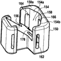
图6至图9示出的分隔件110与图3至图5中所示的分隔件大体相同。分隔件本体150构成固定系统的固定部,部件152构成移动部。分隔件本体150设有腔室或壳体154,该腔室或壳体具有倾斜端面156和内部前表面158。腔室154开口至本体150的上表面150a。移动部152具有下表面160,所述下表面160可抵靠腔室154的倾斜端面156滑动。如同图3至图5所示的实施例,分隔件本体150具有两个侧向槽162和164以及用于使绑带28的端部28e、28f穿过的一个轴向槽166。腔室154的内部前表面限定两个夹持表面154a和154b。移动部152具有前表面168,该前表面168本身限定有两个夹持表面168a和168b,这两个夹持表面168a和168b适于与分隔件本体150的夹持表面154a和154b配合。The
如同图3至图5所示的实施例,通过使移动部152在腔室154中相对于固定部150移动,使得两对夹持表面154a、168a以及154b、168b相互靠近或相互远离地移动。优选地,这种运动在螺栓170的帮助下实现,该螺栓的螺栓头172顶靠在移动部152的上表面152a上,该螺栓170的螺纹部分174畅通地穿过形成于移动部152的椭圆孔176,同时与形成于分隔件本体150的端壁中的内螺纹178配合。通过旋拧螺栓170,借助螺栓头172对移动部152的上表面152a的顶靠,促使移动部152相对于固定部150移动,由此将绑带28固定到分隔件110。As in the embodiment shown in FIGS. 3-5 , the two pairs of clamping
参照图10至图12,接下来描述的是装配有绑带固定系统的分隔件110的另一实施例。与图3至图7的其它分隔件相同,分隔件110包括:本体180和移动部182,该本体180构成绑带固定系统的固定部,该移动部182安装成在腔室或壳体184中滑动,该腔室或壳体184形成于分隔件的本体180中并开口至分隔件本体180的近端表面180a。参照图12,腔室184的底部由大体水平的底壁186限定,该底壁186限定有滑动表面186a,移动部182的大体水平的底壁188的同样的滑动表面182a可在该滑动表面186a上滑动。Referring to FIGS. 10 to 12 , another embodiment of a
移动部182在其水平底壁188的上方具有在两个凸缘192与194之间限定的轴向通路190。如图12较佳所示,轴向通路190的下表面196具有大体水平的部分196a和倾斜的部分196b。移动部182的凸缘192和194设有各自的内部通道198和200,以使绑带28的一部分穿过,所述通道198和200平行于移动部182的移动方向延伸。分隔件本体180在其顶壁187中包括适于与螺栓204配合的内螺纹孔202。内螺纹孔202开口至壳体184。如图10中更清楚所示,分隔件本体180还具有侧部槽206、207以使绑带28的一部分穿过。如图10所示,绑带28的端部28e、28f经由侧部槽206、207穿入到壳体184中,并穿过移动部182的槽198和200,以使绑带28的端部28e和28f从移动部182穿出。移动部182的凸缘192和194的远端表面192a和194a限定夹持表面,所述夹持表面适于与壳体184的远端竖向夹持表面184a配合(见图12)。The moving part 182 has above its horizontal bottom wall 188 an axial passage 190 defined between two flanges 192 and 194 . As best shown in FIG. 12, the lower surface 196 of the axial passageway 190 has a generally horizontal portion 196a and a sloped portion 196b. The flanges 192 and 194 of the moving part 182 are provided with respective
分隔件110的远端208具有用于绑带28的畅通的通道210。The distal end 208 of the
如图12所示,螺栓204的底端204a与通路190的下表面196的倾斜部分196b配合。因此,通过旋拧螺栓204,可使移动部182在一个方向或另一个方向上相对于本体180移动。这起到将绑带28的一部分夹持在固定部180的夹持表面184a与移动部182的夹持表面192a、194a之间的作用。As shown in FIG. 12 , the bottom end 204a of the bolt 204 engages the sloped portion 196b of the lower surface 196 of the passageway 190 . Thus, by turning the bolt 204, the moving part 182 can be moved relative to the
参照图13和图14,接下来描述的是装配有绑带固定系统的分隔件110的另一实施例,该实施例与图6至图9的实施例非常相似。该实施例与图6至图9的实施例的不同之处主要在于:移动部细分为两个独立的移动部,其分别由附图标记210和212指定。这两个移动部210和212可在形成于分隔件本体216中的壳体214内平移式移动。各个半移动部210和212装配有用于控制其移动的螺栓218和219,每个螺栓都具有与图6至图9所示的分隔件110中的螺栓172完全相同的功能。通过半移动部210和212的近端所限定的夹持表面210a和212a中的每一个夹持表面与构成壳体214的本体的近端壁的一部分所限定的共用夹持表面220a之间配合,将绑带28夹持并由此固定到分隔件110。该实施例的优点在于:使得绑带28的每个端部28e、28f都能够单独地固定到分隔件110,由此允许在特定的情况下,外科医生能够进行特定的调整。Referring to Figures 13 and 14, described next is another embodiment of a
在图15至图17中,示出了设有固定系统的分隔件110的另一实施例。In FIGS. 15 to 17 another embodiment of a
在该实施例中,固定系统的固定部由分隔件本体270构成。在分隔件本体的近端部270a中,设有用于容纳移动部274的壳体272。壳体272的底壁构成用于绑带28的第一夹持表面276。移动部274的下表面构成第二夹持表面278。控制螺栓280使移动部274沿方向XX’(见图16)平移式移动,该控制螺栓280的螺纹部分280a与形成于分隔件本体270中的内螺纹282配合。螺栓280的螺栓头280b顶靠在形成于移动部274中的沉孔284的底面上。In this embodiment, the fixing part of the fixing system is constituted by the
绑带28的端部28e、28f插入夹持表面276与278之间,并经由形成于移动部274中的槽288从移动部274中拉出。通过作用于螺栓280,夹持表面276和278可相互远离或相互靠近地移动。The ends 28e, 28f of the
应该注意到,上述绑带固定系统都具有相同的总体结构。这些绑带固定系统包括相对于彼此可移动的两个部件,而且绑带28的自由端部28e、28f插入到这两个部件之间。机械构件(通常为螺栓)起到促使两个部件相互靠近或相互远离地移动的作用。当两个部件相互靠近地移动时,两个绑带部分因受到夹持或挤压而固定到分隔件。It should be noted that the strap securing systems described above all have the same general structure. These strap fixing systems comprise two parts that are movable relative to each other and between which the
图18示出了根据本发明的稳固系统的另一实施例。Figure 18 shows another embodiment of the stabilization system according to the invention.
图18的稳固系统与图2所示的稳固系统的不同之处在于:设有绑带固定系统的分隔件为不同的型式。The securing system of Figure 18 differs from the securing system shown in Figure 2 in that the partitions provided with the strap fixing system are of a different type.
总的来说,这种稳固系统采用的是与图2所示完全相同的形式,包括简单分隔件12、12’和绑带28,所述简单分隔件12、12’插入到椎骨V1与V2之间以及椎骨V3与V4之间,所述绑带28与分隔件12、12’配合。这种稳固系统还包括带有绑带固定系统的分隔件220。In general, this stabilization system takes exactly the same form as that shown in Figure 2, comprising
分隔件220与分隔件110的不同之处主要在于:与分隔件220相连以将绑带28固定到该分隔件220的绑带固定系统222可拆离分隔件220的本体224。更确切地,优选通过下述夹合系统将绑带固定系统固定到分隔件本体224。The
图19至图21示出了分隔件220及其固定系统222。PCT专利申请WO 2007/099258中已经详细地描述了这种优选适于侧向插入的分隔件220。因此,在此仅对分隔件220进行简要描述。19 to 21 show a
通过夹合紧固系统将固定系统222紧固到分隔件本体224的近端226,该夹合紧固系统由诸如两个钉扣228构成,所述钉扣228由绑带固定系统222的两个侧面支承,而且适于与形成于分隔件本体224的近端226的相对侧壁中、可弹性变形的缺口230配合。如图21中更清楚地所示,通过在绑带固定系统222的本体232中制出的狭槽系统,将绑带28固定到分隔件220。The
在PCT专利申请WO 2007/120277中更详细地描述了这种包括两个自锁式狭槽系统的绑带固定系统222。其中具有两个倾斜的侧部槽234和236以及轴向槽238。侧部槽234和236与固定系统222的本体232的内表面232a配合而限定边缘240和242。图21示出了绑带28在固定系统222的本体232内顺沿的路径。绑带28的自由端部28e和28f穿过槽234、236、238。由于绑带28沿蜿蜒的路径穿过狭槽系统,所以通过锁住绑带28而将绑带的各个自由端部28e、28f固定到绑带固定系统(并因而固定到分隔件220),由此确保对绑带28的中间部分施加牵引力时通过摩擦力使绑带自锁。Such a
当固定系统222已经夹合到分隔件本体224上时,并当外科医生对绑带的自由端部28e和28f施加适当的牵引力时(通常利用外科工具),特别是由于存在边缘240和242,使绑带28挤压在固定系统的本体232中。When the
如同上述其它的分隔件那样,分隔件220的本体224的远端具有用于容纳绑带28的中间部分的内部通道244。内部通道244相对于分隔件220的中间平面M’定位在绑带固定系统222的相对侧(见图19)。As with the other dividers described above, the distal end of the
图22至图26示出了根据本发明的稳固系统的其它实例。Figures 22 to 26 show other examples of stabilization systems according to the invention.
图22所示的第一实例与图1所示的实施例非常相似。区别在于:图22所示的第一实例不具有简单分隔件12,简单分隔件12由具有绑带固定系统的分隔件115取代。分隔件115可具有与分隔件110相同的结构,但分隔件115的使用方法不同。分隔件115不是用于固定绑带的自由端部28e、28f,而是用于引导绑带的一个中间部分28d。绑带28经由槽134’(相当于图3和图4所示的槽134)进入,并经由类似的第二槽136’(相当于图3和图4的槽136)离开。The first example shown in FIG. 22 is very similar to the embodiment shown in FIG. 1 . The difference is that the first example shown in Figure 22 does not have a
分隔件115并非仅仅具有引导绑带28的中间部分28d的功能,还具有夹持该中间部分28d的功能。因此,分隔件115不仅执行引导功能,还通过使分隔件的移动部(相当于图4和图5所示的移动部122)相对于分隔件的固定部(相当于图4和图5所示的固定部120)移动而执行夹持绑带28的中间部分的功能。The
分隔件115还具有内部通道140’(相当于图3和图5所示的内部通道140),该内部通道140’延伸穿过分隔件的固定部的远端部,以引导绑带28的另一中间部分28c。The
因此,分隔件115具有用于引导绑带28的两个中间部分28c、28d的引导装置,但是不具有固定绑带28的自由端部28e、28f的功能,固定绑带28的自由端部28e、28f的功能由分隔件110执行。Thus, the
在图23中,示出了稳固系统的另一实例。在该实例中,具有三个分隔件110、115、115’。这些分隔件中的每一个分隔件都具有绑带固定系统,但仅仅分隔件110的绑带固定系统用于容纳和固定绑带28的自由端部28e、28f。分隔件115、115’的每一个分隔件用于引导绑带28的两个中间部分28c、28d、28c’、28d’。可选择地,分隔件115和/或115’可用于夹持所述两个中间部分28d、28d’的其中之一。In Fig. 23, another example of a stabilization system is shown. In this example, there are three
图22和图23中示出的分隔件100、115以及115’与图3至图5中示出的分隔件110相似,当然,图22和图23中示出的分隔件100、115以及115’可以与图6至图17中示出的分隔件110的其它实例相似。The
当然,可以使用下面的稳固系统,包括:Of course, the following stabilization systems are available, including:
——分隔件110,该分隔件110设有用于固定绑带28的自由端部28e、28f的绑带固定系统;以及- a
——至少一个简单分隔件,例如,图27所示的、仅用于引导绑带28的两个中间部分的分隔件12,和/或至少一个分隔件,例如,用于引导绑带28的两个中间部分、并且可能用于夹持这两个中间部分的其中之一的分隔件115。- at least one simple divider, such as the
图24示出了图22的变型,该变型与图22的不同之处在于:采用不同的侧向接入方式将分隔件110和115插入到椎骨V1、V2以及V3的棘突之间。换言之,从椎骨的一侧将分隔件110侧向插入到椎骨V2与V3之间,而从椎骨的另一侧将分隔件115侧向插入到椎骨V1与V2之间。因此,分隔件115的远端与分隔件110的近端在竖直方向上对齐。Fig. 24 shows a variation of Fig. 22, which differs from Fig. 22 in that the
图25示出了根据本发明的稳固系统的另一变型。在该变型中,稳固系统包括两个柔性绑带27、29,这两个柔性绑带27、29适于围绕三个椎骨V1、V2、V3的棘突而共同形成单个圈。各个绑带27(29)具有两个自由端部27e、27f(29e、29f)以及其间的中间部分27a(29a)。稳固系统还包括两个分隔件300和302,各个分隔件300(302)设有:Figure 25 shows another variant of the stabilization system according to the invention. In this variant, the stabilization system comprises two
——绑带固定系统304(306),该绑带固定系统适于将所述两个绑带27、29的每一个绑带的一个自由端部27e、29e(27f、29f)固定到分隔件300(302);以及- a strap fixing system 304 (306) adapted to fix one
——引导装置,该引导装置用于引导所述绑带的其中之一的中间部分29a(27a)。- Guiding means for guiding the
因此,如图25所示,分隔件300用于固定绑带27的自由端部27e和绑带29的自由端部29e,并用于引导绑带29的中间部分29a;分隔件302用于固定绑带27的自由端部27f和绑带29的自由端部29f,并用于引导绑带27的中间部分27a。Therefore, as shown in Figure 25, the
分隔件300和302与图3至图17中所示的分隔件110的其中一个实例相似。
应该注意到,分隔件300、302的其中之一首先用于将两个绑带27和29固定在一起,而另一分隔件用于在外科医生对绑带的两个剩余的自由端部施加适量的牵引力之后固定这些剩余的自由端部,这些剩余的自由端部从所述另一分隔件中穿出。It should be noted that one of the
作为容易实现的功能,该方案可通过分隔件300、302中的一个分隔件或另一分隔件对绑带27、29施加牵引力,或者通过其中一个分隔件对绑带27、29的自由端部施加牵引力而开始,通过另一分隔件对绑带施加牵引力而结束。As an easy-to-implement function, this solution can apply traction to the
在图25中,从椎骨的一侧将分隔件300侧向插入到椎骨V1与V2之间,而从椎骨的另一侧将分隔件302侧向插入到椎骨V2与V3之间。在图26的变型中,从椎骨V1、V2、V3的同一侧侧向插入两个分隔件300和302。在图26的变型中,两个绑带27、29中的一个绑带比另一绑带长。In Fig. 25,
Claims (11)
Applications Claiming Priority (3)
| Application Number | Priority Date | Filing Date | Title |
|---|---|---|---|
| EP08305183.9 | 2008-05-20 | ||
| EP08305183 | 2008-05-20 | ||
| PCT/EP2009/056168 WO2009141393A1 (en) | 2008-05-20 | 2009-05-20 | System for stabilizing at least three vertebrae |
Publications (2)
| Publication Number | Publication Date |
|---|---|
| CN102036614A true CN102036614A (en) | 2011-04-27 |
| CN102036614B CN102036614B (en) | 2013-03-27 |
Family
ID=39846969
Family Applications (1)
| Application Number | Title | Priority Date | Filing Date |
|---|---|---|---|
| CN200980118197.6A Expired - Fee Related CN102036614B (en) | 2008-05-20 | 2009-05-20 | System for stabilizing at least three vertebrae |
Country Status (8)
| Country | Link |
|---|---|
| US (1) | US8663283B2 (en) |
| EP (1) | EP2303163B1 (en) |
| CN (1) | CN102036614B (en) |
| AT (1) | ATE534339T1 (en) |
| AU (1) | AU2009248781A1 (en) |
| CA (1) | CA2722966C (en) |
| ES (1) | ES2378142T3 (en) |
| WO (1) | WO2009141393A1 (en) |
Cited By (3)
| Publication number | Priority date | Publication date | Assignee | Title |
|---|---|---|---|---|
| CN109069195A (en) * | 2016-02-15 | 2018-12-21 | 巴克博恩公司 | Dynamic stability vertebral implant and surgical operation packet including the dynamic stability vertebral implant |
| CN109069193A (en) * | 2016-02-15 | 2018-12-21 | 巴克博恩公司 | Dynamic stability intervertebral implant and the tool for placing the dynamic stability intervertebral implant |
| CN110507402A (en) * | 2019-07-23 | 2019-11-29 | 苏州麦禾生物科技有限公司 | A kind of safety-type orthopedic instrument |
Families Citing this family (44)
| Publication number | Priority date | Publication date | Assignee | Title |
|---|---|---|---|---|
| US8241330B2 (en) | 2007-01-11 | 2012-08-14 | Lanx, Inc. | Spinous process implants and associated methods |
| US9055981B2 (en) | 2004-10-25 | 2015-06-16 | Lanx, Inc. | Spinal implants and methods |
| FR2890851B1 (en) | 2005-09-21 | 2008-06-20 | Abbott Spine Sa | ANCILLARY TO TENSION A FLEXIBLE LINK. |
| US9265532B2 (en) | 2007-01-11 | 2016-02-23 | Lanx, Inc. | Interspinous implants and methods |
| US20110172708A1 (en) * | 2007-06-22 | 2011-07-14 | Simpirica Spine, Inc. | Methods and systems for increasing the bending stiffness of a spinal segment with elongation limit |
| FR2921248A1 (en) | 2007-09-25 | 2009-03-27 | Abbott Spine Sa | DEVICE FOR TIGHTENING TWO PORTIONS OF A BRAID AND INTERVERTEBRAL IMPLANT COMPRISING A BILGE, A BRAID AND A SUCH TIGHTENING DEVICE |
| US8128635B2 (en) | 2007-10-23 | 2012-03-06 | Zimmer Spine S.A.S. | Bone fixation tensioning tool and method |
| ATE515239T1 (en) | 2008-04-24 | 2011-07-15 | Zimmer Spine | SYSTEM FOR STABILIZING AT LEAST ONE SECTION OF THE SPINE |
| WO2009141393A1 (en) | 2008-05-20 | 2009-11-26 | Zimmer Spine | System for stabilizing at least three vertebrae |
| WO2009149407A1 (en) * | 2008-06-06 | 2009-12-10 | Simpirica Spine, Inc. | Methods and apparatus for locking a band |
| WO2010014119A1 (en) | 2008-07-29 | 2010-02-04 | Synthes (U.S.A) | Crimp with an insert to hold a cable |
| MX2011010375A (en) | 2009-03-31 | 2012-02-23 | Lanx Inc | Spinous process implants and associated methods. |
| FR2954905B1 (en) | 2010-01-06 | 2012-12-28 | Implanet | DEVICE FOR FIXING VERTEBRAL |
| US8740949B2 (en) | 2011-02-24 | 2014-06-03 | Spinal Elements, Inc. | Methods and apparatus for stabilizing bone |
| AU2012308347C1 (en) | 2011-09-14 | 2018-07-19 | Orthopediatrics Corp. | Tether clamp and implantation system |
| JP2014533136A (en) | 2011-10-05 | 2014-12-11 | マーク・エイ・ドッドソン | Module retractor and related methods |
| US11812923B2 (en) | 2011-10-07 | 2023-11-14 | Alan Villavicencio | Spinal fixation device |
| US20130110173A1 (en) * | 2011-10-28 | 2013-05-02 | Warsaw Orthopedic, Inc. | Attachment mechanism for material and bone |
| KR101121667B1 (en) * | 2012-01-17 | 2012-03-09 | 김창국 | Interspinous spinal spacer |
| US10548644B2 (en) | 2013-03-05 | 2020-02-04 | Globus Medical, Inc. | Elastic member clamps |
| AU2014201336B2 (en) | 2013-03-11 | 2018-04-19 | K2M, Inc. | Flexible Fastening System |
| US9421044B2 (en) * | 2013-03-14 | 2016-08-23 | Spinal Elements, Inc. | Apparatus for bone stabilization and distraction and methods of use |
| US10154861B2 (en) * | 2013-03-15 | 2018-12-18 | Jcbd, Llc | Spinal stabilization system |
| US11213325B2 (en) * | 2013-03-15 | 2022-01-04 | Jcbd, Llc | Spinal stabilization system with adjustable interlaminar devices |
| US9839450B2 (en) | 2013-09-27 | 2017-12-12 | Spinal Elements, Inc. | Device and method for reinforcement of a facet |
| FR3012032B1 (en) | 2013-10-18 | 2015-12-11 | Implanet | DEVICE AND SYSTEM FOR VERTICAL FASTENING FOR HOLDING A VERTEBRA ON A ROD, METHOD OF BLOCKING A LOOP WITH SUCH A DEVICE. |
| US9402666B2 (en) * | 2014-04-30 | 2016-08-02 | King Faisal Specialist Hospital & Research Centre | Vertebral fixation device |
| WO2016044432A1 (en) | 2014-09-17 | 2016-03-24 | Spinal Elements, Inc. | Flexible fastening band connector |
| US9931138B2 (en) | 2014-10-15 | 2018-04-03 | Globus Medical, Inc. | Orthopedic extendable rods |
| US10548639B2 (en) | 2015-04-24 | 2020-02-04 | K2M, Inc. | Tethering screw system |
| FR3035584B1 (en) * | 2015-04-29 | 2017-05-19 | Medicrea Int | MATERIAL OF VERTEBRAL OSTEOSYNTHESIS |
| JP7203011B2 (en) | 2016-07-26 | 2023-01-12 | バンド-ロック,エルエルシー | Orthopedic constrained implants and systems |
| WO2018071514A1 (en) | 2016-10-11 | 2018-04-19 | K2M, Inc. | Spinal implant and methods of use thereof |
| JP6871709B2 (en) * | 2016-10-12 | 2021-05-12 | HOYA Technosurgical株式会社 | Spacer |
| US10307186B2 (en) * | 2016-12-02 | 2019-06-04 | Nuvasive, Inc. | Surgical band clamp system |
| FR3070125B1 (en) * | 2017-08-16 | 2019-09-13 | Backbone | ASSEMBLY ASSEMBLY FOR POSITIONING AN INTERVERTEBRAL IMPLANT AND SURGICAL KIT INCORPORATING IT |
| AU2019280691B2 (en) * | 2018-06-05 | 2024-10-31 | Vb Spine Us Opco Llc | Band clamp, band clamp assembly |
| AU2020278453A1 (en) | 2019-05-22 | 2022-01-20 | Spinal Elements, Inc. | Bone tie and bone tie inserter |
| US11457959B2 (en) | 2019-05-22 | 2022-10-04 | Spinal Elements, Inc. | Bone tie and bone tie inserter |
| US11304733B2 (en) | 2020-02-14 | 2022-04-19 | Spinal Elements, Inc. | Bone tie methods |
| CO2021002454A1 (en) | 2021-02-24 | 2021-03-29 | Chaparro Mario Valderrama | Molded, clamped blades for osteosynthesis and orthotics and manufacturing process |
| US11723694B2 (en) * | 2021-03-31 | 2023-08-15 | Bret Michael Berry | Adjustable spinous process implant |
| WO2023108007A2 (en) | 2021-12-10 | 2023-06-15 | Spinal Elements, Inc. | Bone tie and portal |
| FR3146397B1 (en) * | 2023-03-07 | 2025-03-07 | Backbone | DYNAMIC STABILIZATION SPINAL IMPLANT |
Family Cites Families (71)
| Publication number | Priority date | Publication date | Assignee | Title |
|---|---|---|---|---|
| US902040A (en) | 1906-03-12 | 1908-10-27 | Homer W Wyckoff | Wire-connector. |
| US1346940A (en) | 1919-10-28 | 1920-07-20 | Asa W Collins | Apparatus for binding fractured bones |
| FR522040A (en) | 1920-08-07 | 1921-07-24 | Auguste Henri Contassot | Ligating device |
| US2049361A (en) | 1934-10-27 | 1936-07-28 | Ericsson Ernst Axel Johan | Wire or ribbon tightening apparatus |
| US5030220A (en) | 1990-03-29 | 1991-07-09 | Advanced Spine Fixation Systems Incorporated | Spine fixation system |
| FR2693364B1 (en) | 1992-07-07 | 1995-06-30 | Erpios Snc | INTERVERTEBRAL PROSTHESIS FOR STABILIZING ROTATORY AND FLEXIBLE-EXTENSION CONSTRAINTS. |
| GB9217578D0 (en) | 1992-08-19 | 1992-09-30 | Surgicarft Ltd | Surgical implants,etc |
| US5356412A (en) | 1992-10-09 | 1994-10-18 | United States Surgical Corporation | Sternum buckle with rotational engagement and method of closure |
| AU3502893A (en) | 1993-01-19 | 1994-08-15 | Jbs Sa | Spinal osteosynthesis device |
| US5413576A (en) | 1993-02-10 | 1995-05-09 | Rivard; Charles-Hilaire | Apparatus for treating spinal disorder |
| FR2704745B1 (en) | 1993-05-07 | 1995-11-24 | Erpios | Device for connecting the ends of a ligament for osteosynthesis, in particular for vertebral osteosynthesis. |
| FR2722088B1 (en) | 1994-07-08 | 1998-01-23 | Cahlik Marc Andre | SURGICAL IMPLANT FOR STABILIZING THE INTERVERTEBRAL SPACE |
| FR2731344B1 (en) | 1995-03-06 | 1997-08-22 | Dimso Sa | SPINAL INSTRUMENTATION ESPECIALLY FOR A ROD |
| FR2742649B1 (en) | 1995-12-22 | 1998-04-10 | Robert Louis Boutet | STRAPPING LINK FOR MEDICAL USE AND METHOD OF LAYING THE SAME |
| US5667508A (en) | 1996-05-01 | 1997-09-16 | Fastenetix, Llc | Unitary locking cap for use with a pedicle screw |
| US5702399A (en) | 1996-05-16 | 1997-12-30 | Pioneer Laboratories, Inc. | Surgical cable screw connector |
| DE19716504A1 (en) | 1997-04-19 | 1998-12-03 | Hinze Manfred Dr Med Habil | Compression hoop for applying metal band around bone |
| US5964769A (en) | 1997-08-26 | 1999-10-12 | Spinal Concepts, Inc. | Surgical cable system and method |
| US6053921A (en) | 1997-08-26 | 2000-04-25 | Spinal Concepts, Inc. | Surgical cable system and method |
| US6179838B1 (en) | 1998-02-24 | 2001-01-30 | Daniel Fiz | Bone fixation arrangements and method |
| US6569164B1 (en) | 1998-04-29 | 2003-05-27 | Stryker Spine | Spinal osteosynthesis system for anterior fixation |
| US6099527A (en) | 1998-04-30 | 2000-08-08 | Spinal Concepts, Inc. | Bone protector and method |
| US6086590A (en) | 1999-02-02 | 2000-07-11 | Pioneer Laboratories, Inc. | Cable connector for orthopaedic rod |
| US6299613B1 (en) | 1999-04-23 | 2001-10-09 | Sdgi Holdings, Inc. | Method for the correction of spinal deformities through vertebral body tethering without fusion |
| US6316185B1 (en) * | 1999-09-29 | 2001-11-13 | Mountain View Pharmaceuticals, Inc. | Quantitation of viruses by light scattering |
| FR2799948B1 (en) | 1999-10-22 | 2002-03-29 | Transco Esquisse | CONNECTION BAR FOR ANCHORING AN INTER-THINNING PROSTHESIS |
| US6514255B1 (en) | 2000-02-25 | 2003-02-04 | Bret Ferree | Sublaminar spinal fixation apparatus |
| US6547770B2 (en) | 2000-04-14 | 2003-04-15 | Aiolos Systems Aktiebolag (Ab) | Ophthalmic dispensing device |
| JP2001299770A (en) | 2000-04-20 | 2001-10-30 | Azwell Inc | Clip for bone fixing string |
| GB0018826D0 (en) | 2000-08-02 | 2000-09-20 | Depuy Int Ltd | Improvements in and relating to fixings |
| US6554831B1 (en) | 2000-09-01 | 2003-04-29 | Hopital Sainte-Justine | Mobile dynamic system for treating spinal disorder |
| EP1502552A3 (en) | 2000-10-24 | 2005-03-16 | The Spineology Group, LLC | Tension band clip |
| FR2817929B1 (en) | 2000-12-07 | 2003-03-21 | Spine Next Sa | DEVICE FOR FIXING A ROD AND A SPHERICAL SYMMETRY SCREW HEAD |
| FR2818530B1 (en) | 2000-12-22 | 2003-10-31 | Spine Next Sa | INTERVERTEBRAL IMPLANT WITH DEFORMABLE SHIM |
| FR2822051B1 (en) | 2001-03-13 | 2004-02-27 | Spine Next Sa | INTERVERTEBRAL IMPLANT WITH SELF-LOCKING ATTACHMENT |
| US6478798B1 (en) | 2001-05-17 | 2002-11-12 | Robert S. Howland | Spinal fixation apparatus and methods for use |
| WO2003007829A1 (en) | 2001-07-20 | 2003-01-30 | Spinal Concepts, Inc. | Spinal stabilization system and method |
| US7048736B2 (en) * | 2002-05-17 | 2006-05-23 | Sdgi Holdings, Inc. | Device for fixation of spinous processes |
| GB0212948D0 (en) | 2002-06-06 | 2002-07-17 | Grampian Univ Hospitals | Manipulator |
| FR2842724B1 (en) | 2002-07-23 | 2005-05-27 | Spine Next Sa | VERTEBRAL FASTENING SYSTEM |
| US7250054B2 (en) | 2002-08-28 | 2007-07-31 | Smith & Nephew, Inc. | Systems, methods, and apparatuses for clamping and reclamping an orthopedic surgical cable |
| US20060064165A1 (en) | 2004-09-23 | 2006-03-23 | St. Francis Medical Technologies, Inc. | Interspinous process implant including a binder and method of implantation |
| US7909853B2 (en) * | 2004-09-23 | 2011-03-22 | Kyphon Sarl | Interspinous process implant including a binder and method of implantation |
| US7094240B2 (en) | 2003-01-10 | 2006-08-22 | Sdgi Holdings, Inc. | Flexible member tensioning instruments and methods |
| US7335203B2 (en) * | 2003-02-12 | 2008-02-26 | Kyphon Inc. | System and method for immobilizing adjacent spinous processes |
| FR2858929B1 (en) | 2003-08-21 | 2005-09-30 | Spine Next Sa | "INTERVERTEBRAL IMPLANT FOR LOMBO-SACRED JOINT" |
| DE10348329B3 (en) | 2003-10-17 | 2005-02-17 | Biedermann Motech Gmbh | Rod-shaped element used in spinal column and accident surgery for connecting two bone-anchoring elements comprises a rigid section and an elastic section that are made in one piece |
| FR2867057B1 (en) | 2004-03-02 | 2007-06-01 | Spinevision | DYNAMIC BONDING ELEMENT FOR A SPINAL FIXING SYSTEM AND FIXING SYSTEM COMPRISING SUCH A CONNECTING MEMBER |
| FR2870106B1 (en) * | 2004-05-11 | 2007-07-27 | Spine Next Sa | INTERVERTEBRAL IMPLANT |
| FR2870107B1 (en) | 2004-05-11 | 2007-07-27 | Spine Next Sa | SELF-LOCKING DEVICE FOR FIXING AN INTERVERTEBRAL IMPLANT |
| FR2870109B1 (en) * | 2004-05-17 | 2007-04-13 | Spine Next Sa | INTERVERTEBRAL BLADE FOR CERVICAL VERTEBRATES |
| FR2870718B1 (en) | 2004-05-25 | 2006-09-22 | Spine Next Sa | TREATMENT ASSEMBLY FOR THE DEGENERATION OF AN INTERVERTEBRAL DISC |
| DK1781961T3 (en) | 2004-06-09 | 2013-08-26 | Kinamed Inc | High voltage surgical cable locking device |
| US8123807B2 (en) * | 2004-10-20 | 2012-02-28 | Vertiflex, Inc. | Systems and methods for posterior dynamic stabilization of the spine |
| US8696707B2 (en) | 2005-03-08 | 2014-04-15 | Zyga Technology, Inc. | Facet joint stabilization |
| FR2884135B1 (en) | 2005-04-07 | 2007-06-22 | Abbott Spine Sa | INTERVERTEBRAL IMPLANT FOR LOMBO-SACRED JOINT |
| FR2884136B1 (en) | 2005-04-08 | 2008-02-22 | Spinevision Sa | INTERVERTEBRAL SURGICAL IMPLANT FORMING BALL |
| US7789898B2 (en) * | 2005-04-15 | 2010-09-07 | Warsaw Orthopedic, Inc. | Transverse process/laminar spacer |
| FR2889937B1 (en) | 2005-08-26 | 2007-11-09 | Abbott Spine Sa | INTERVERTEBRAL IMPLANT FOR LOMBO-SACRED JOINT |
| FR2890850B1 (en) | 2005-09-20 | 2009-04-17 | Abbott Spine Sa | VERTEBRAL FASTENING SYSTEM |
| FR2890851B1 (en) | 2005-09-21 | 2008-06-20 | Abbott Spine Sa | ANCILLARY TO TENSION A FLEXIBLE LINK. |
| EP1815812B1 (en) | 2006-02-03 | 2009-07-29 | Spinelab AG | Spinal implant |
| FR2897771B1 (en) | 2006-02-28 | 2008-06-06 | Abbott Spine Sa | INTERVERTEBRAL IMPLANT |
| US7508586B2 (en) | 2006-04-14 | 2009-03-24 | Southwall Technologies, Inc. | Zinc-based film manipulation for an optical filter |
| US20070299445A1 (en) | 2006-06-22 | 2007-12-27 | Shadduck John H | Spine treatment devices and methods |
| WO2008051801A2 (en) * | 2006-10-19 | 2008-05-02 | Simpirica Spine, Inc. | Structures and methods for constraining spinal processes with single connector |
| US8740941B2 (en) | 2006-11-10 | 2014-06-03 | Lanx, Inc. | Pedicle based spinal stabilization with adjacent vertebral body support |
| US20080114357A1 (en) * | 2006-11-15 | 2008-05-15 | Warsaw Orthopedic, Inc. | Inter-transverse process spacer device and method for use in correcting a spinal deformity |
| US8109978B2 (en) | 2006-11-28 | 2012-02-07 | Anova Corporation | Methods of posterior fixation and stabilization of a spinal segment |
| ATE515239T1 (en) | 2008-04-24 | 2011-07-15 | Zimmer Spine | SYSTEM FOR STABILIZING AT LEAST ONE SECTION OF THE SPINE |
| WO2009141393A1 (en) | 2008-05-20 | 2009-11-26 | Zimmer Spine | System for stabilizing at least three vertebrae |
-
2009
- 2009-05-20 WO PCT/EP2009/056168 patent/WO2009141393A1/en not_active Ceased
- 2009-05-20 CN CN200980118197.6A patent/CN102036614B/en not_active Expired - Fee Related
- 2009-05-20 AU AU2009248781A patent/AU2009248781A1/en not_active Abandoned
- 2009-05-20 US US12/469,414 patent/US8663283B2/en active Active
- 2009-05-20 AT AT09749883T patent/ATE534339T1/en active
- 2009-05-20 CA CA2722966A patent/CA2722966C/en not_active Expired - Fee Related
- 2009-05-20 EP EP09749883A patent/EP2303163B1/en not_active Not-in-force
- 2009-05-20 ES ES09749883T patent/ES2378142T3/en active Active
Cited By (5)
| Publication number | Priority date | Publication date | Assignee | Title |
|---|---|---|---|---|
| CN109069195A (en) * | 2016-02-15 | 2018-12-21 | 巴克博恩公司 | Dynamic stability vertebral implant and surgical operation packet including the dynamic stability vertebral implant |
| CN109069193A (en) * | 2016-02-15 | 2018-12-21 | 巴克博恩公司 | Dynamic stability intervertebral implant and the tool for placing the dynamic stability intervertebral implant |
| CN109069195B (en) * | 2016-02-15 | 2021-05-04 | 巴克博恩公司 | Dynamically stabilized vertebral implant and surgical kit including the same |
| CN109069193B (en) * | 2016-02-15 | 2021-07-23 | 巴克博恩公司 | Dynamically stabilized intervertebral implant and tool for placing the same |
| CN110507402A (en) * | 2019-07-23 | 2019-11-29 | 苏州麦禾生物科技有限公司 | A kind of safety-type orthopedic instrument |
Also Published As
| Publication number | Publication date |
|---|---|
| EP2303163A1 (en) | 2011-04-06 |
| AU2009248781A1 (en) | 2009-11-26 |
| CA2722966C (en) | 2016-07-05 |
| ES2378142T3 (en) | 2012-04-09 |
| EP2303163B1 (en) | 2011-11-23 |
| US20090292317A1 (en) | 2009-11-26 |
| CN102036614B (en) | 2013-03-27 |
| WO2009141393A1 (en) | 2009-11-26 |
| ATE534339T1 (en) | 2011-12-15 |
| CA2722966A1 (en) | 2009-11-26 |
| US8663283B2 (en) | 2014-03-04 |
Similar Documents
| Publication | Publication Date | Title |
|---|---|---|
| CN102036614B (en) | System for stabilizing at least three vertebrae | |
| US8845689B2 (en) | System for stabilizing at least a portion of the spine | |
| US8002805B2 (en) | Intervertebral implant | |
| JP4118050B2 (en) | Intervertebral implant | |
| AU2008303511B2 (en) | A device for clamping two portions of a braid and an intervertebral implant comprising a spacer, a braid, and such a clamping device | |
| US9788875B2 (en) | Crimp with an insert to hold a cable | |
| RU2308897C2 (en) | Fixing device for fixing vertebral segments | |
| EP2138122A1 (en) | Stabilization system between a sacrum and a lumbar vertebra | |
| US7150757B2 (en) | Adjustable line locks and methods | |
| KR102174538B1 (en) | Device for compression across fractures | |
| JP2007536966A (en) | Self-locking device for securing an intervertebral implant | |
| US9427263B2 (en) | Device for fixing a bony structure to a support member | |
| JP7280340B2 (en) | Telescoping tether clamping assembly and related methods and apparatus | |
| JP2004535846A (en) | Self-locking intervertebral implant | |
| US20110034958A1 (en) | Adjustable sternal clamp array | |
| JP2009508609A (en) | Vertebral fixation system | |
| CN103153218A (en) | Anchor for attachment to a bony structure | |
| US10123832B2 (en) | Surgical forceps system | |
| CN101801292A (en) | Fastening element | |
| CN209899481U (en) | A staple cartridge for surgical instruments and surgical instruments | |
| KR101451515B1 (en) | Connector for high tibia osteotomy | |
| CN111184548A (en) | Nail bin for surgical instrument and surgical instrument |
Legal Events
| Date | Code | Title | Description |
|---|---|---|---|
| C06 | Publication | ||
| PB01 | Publication | ||
| C10 | Entry into substantive examination | ||
| SE01 | Entry into force of request for substantive examination | ||
| C53 | Correction of patent of invention or patent application | ||
| CB02 | Change of applicant information |
Address after: bordeaux Applicant after: Zimmer Spine Address before: bordeaux Applicant before: Zimmer Spine Inc. |
|
| COR | Change of bibliographic data |
Free format text: CORRECT: APPLICANT; FROM: ZIMMER SPINE INC. TO: ZIMMER SPINE, INC. |
|
| C14 | Grant of patent or utility model | ||
| GR01 | Patent grant | ||
| C17 | Cessation of patent right | ||
| CF01 | Termination of patent right due to non-payment of annual fee |
Granted publication date: 20130327 Termination date: 20130520 |