CN102072425A - Lighting device - Google Patents
Lighting device Download PDFInfo
- Publication number
- CN102072425A CN102072425A CN201010543783XA CN201010543783A CN102072425A CN 102072425 A CN102072425 A CN 102072425A CN 201010543783X A CN201010543783X A CN 201010543783XA CN 201010543783 A CN201010543783 A CN 201010543783A CN 102072425 A CN102072425 A CN 102072425A
- Authority
- CN
- China
- Prior art keywords
- lighting device
- light
- light emitting
- emitting module
- catoptric arrangement
- Prior art date
- Legal status (The legal status is an assumption and is not a legal conclusion. Google has not performed a legal analysis and makes no representation as to the accuracy of the status listed.)
- Granted
Links
Images


Classifications
-
- F—MECHANICAL ENGINEERING; LIGHTING; HEATING; WEAPONS; BLASTING
- F21—LIGHTING
- F21K—NON-ELECTRIC LIGHT SOURCES USING LUMINESCENCE; LIGHT SOURCES USING ELECTROCHEMILUMINESCENCE; LIGHT SOURCES USING CHARGES OF COMBUSTIBLE MATERIAL; LIGHT SOURCES USING SEMICONDUCTOR DEVICES AS LIGHT-GENERATING ELEMENTS; LIGHT SOURCES NOT OTHERWISE PROVIDED FOR
- F21K9/00—Light sources using semiconductor devices as light-generating elements, e.g. using light-emitting diodes [LED] or lasers
- F21K9/60—Optical arrangements integrated in the light source, e.g. for improving the colour rendering index or the light extraction
-
- F—MECHANICAL ENGINEERING; LIGHTING; HEATING; WEAPONS; BLASTING
- F21—LIGHTING
- F21V—FUNCTIONAL FEATURES OR DETAILS OF LIGHTING DEVICES OR SYSTEMS THEREOF; STRUCTURAL COMBINATIONS OF LIGHTING DEVICES WITH OTHER ARTICLES, NOT OTHERWISE PROVIDED FOR
- F21V29/00—Protecting lighting devices from thermal damage; Cooling or heating arrangements specially adapted for lighting devices or systems
- F21V29/50—Cooling arrangements
- F21V29/70—Cooling arrangements characterised by passive heat-dissipating elements, e.g. heat-sinks
- F21V29/74—Cooling arrangements characterised by passive heat-dissipating elements, e.g. heat-sinks with fins or blades
- F21V29/77—Cooling arrangements characterised by passive heat-dissipating elements, e.g. heat-sinks with fins or blades with essentially identical diverging planar fins or blades, e.g. with fan-like or star-like cross-section
- F21V29/773—Cooling arrangements characterised by passive heat-dissipating elements, e.g. heat-sinks with fins or blades with essentially identical diverging planar fins or blades, e.g. with fan-like or star-like cross-section the planes containing the fins or blades having the direction of the light emitting axis
-
- F—MECHANICAL ENGINEERING; LIGHTING; HEATING; WEAPONS; BLASTING
- F21—LIGHTING
- F21V—FUNCTIONAL FEATURES OR DETAILS OF LIGHTING DEVICES OR SYSTEMS THEREOF; STRUCTURAL COMBINATIONS OF LIGHTING DEVICES WITH OTHER ARTICLES, NOT OTHERWISE PROVIDED FOR
- F21V7/00—Reflectors for light sources
- F21V7/0008—Reflectors for light sources providing for indirect lighting
-
- F—MECHANICAL ENGINEERING; LIGHTING; HEATING; WEAPONS; BLASTING
- F21—LIGHTING
- F21V—FUNCTIONAL FEATURES OR DETAILS OF LIGHTING DEVICES OR SYSTEMS THEREOF; STRUCTURAL COMBINATIONS OF LIGHTING DEVICES WITH OTHER ARTICLES, NOT OTHERWISE PROVIDED FOR
- F21V7/00—Reflectors for light sources
- F21V7/0025—Combination of two or more reflectors for a single light source
- F21V7/0033—Combination of two or more reflectors for a single light source with successive reflections from one reflector to the next or following
- F21V7/0041—Combination of two or more reflectors for a single light source with successive reflections from one reflector to the next or following for avoiding direct view of the light source or to prevent dazzling
-
- F—MECHANICAL ENGINEERING; LIGHTING; HEATING; WEAPONS; BLASTING
- F21—LIGHTING
- F21V—FUNCTIONAL FEATURES OR DETAILS OF LIGHTING DEVICES OR SYSTEMS THEREOF; STRUCTURAL COMBINATIONS OF LIGHTING DEVICES WITH OTHER ARTICLES, NOT OTHERWISE PROVIDED FOR
- F21V7/00—Reflectors for light sources
- F21V7/22—Reflectors for light sources characterised by materials, surface treatments or coatings, e.g. dichroic reflectors
- F21V7/24—Reflectors for light sources characterised by materials, surface treatments or coatings, e.g. dichroic reflectors characterised by the material
- F21V7/26—Reflectors for light sources characterised by materials, surface treatments or coatings, e.g. dichroic reflectors characterised by the material the material comprising photoluminescent substances
-
- F—MECHANICAL ENGINEERING; LIGHTING; HEATING; WEAPONS; BLASTING
- F21—LIGHTING
- F21S—NON-PORTABLE LIGHTING DEVICES; SYSTEMS THEREOF; VEHICLE LIGHTING DEVICES SPECIALLY ADAPTED FOR VEHICLE EXTERIORS
- F21S8/00—Lighting devices intended for fixed installation
- F21S8/04—Lighting devices intended for fixed installation intended only for mounting on a ceiling or the like overhead structures
-
- F—MECHANICAL ENGINEERING; LIGHTING; HEATING; WEAPONS; BLASTING
- F21—LIGHTING
- F21Y—INDEXING SCHEME ASSOCIATED WITH SUBCLASSES F21K, F21L, F21S and F21V, RELATING TO THE FORM OR THE KIND OF THE LIGHT SOURCES OR OF THE COLOUR OF THE LIGHT EMITTED
- F21Y2103/00—Elongate light sources, e.g. fluorescent tubes
- F21Y2103/30—Elongate light sources, e.g. fluorescent tubes curved
- F21Y2103/33—Elongate light sources, e.g. fluorescent tubes curved annular
-
- F—MECHANICAL ENGINEERING; LIGHTING; HEATING; WEAPONS; BLASTING
- F21—LIGHTING
- F21Y—INDEXING SCHEME ASSOCIATED WITH SUBCLASSES F21K, F21L, F21S and F21V, RELATING TO THE FORM OR THE KIND OF THE LIGHT SOURCES OR OF THE COLOUR OF THE LIGHT EMITTED
- F21Y2115/00—Light-generating elements of semiconductor light sources
- F21Y2115/10—Light-emitting diodes [LED]
Landscapes
- Engineering & Computer Science (AREA)
- General Engineering & Computer Science (AREA)
- Physics & Mathematics (AREA)
- Microelectronics & Electronic Packaging (AREA)
- Optics & Photonics (AREA)
- Arrangement Of Elements, Cooling, Sealing, Or The Like Of Lighting Devices (AREA)
- Non-Portable Lighting Devices Or Systems Thereof (AREA)
Abstract
本发明公开了一种照明装置。该照明装置包括:热辐射主体,该热辐射主体包括容纳凹槽;反射结构,该反射结构布置在第一容纳凹槽中并将入射光反射到外部;发光模块单元,该发光模块单元布置在热辐射主体的下部分的周边上并发射光;以及盖,该盖布置在所述发光模块下方并将从发光模块单元发射的光反射到所述反射结构。
The invention discloses a lighting device. The lighting device includes: a heat radiation body, which includes a receiving groove; a reflective structure, which is arranged in the first receiving groove and reflects incident light to the outside; a light emitting module unit, which is arranged in the first receiving groove heat radiates on the periphery of the lower portion of the main body and emits light; and a cover disposed under the light emitting module and reflects light emitted from the light emitting module unit to the reflective structure.
Description
相关申请的交叉引用Cross References to Related Applications
本申请根据美国法典第35条119款要求2009年11月9日提交的韩国专利申请No.10-2009-0107487、No.10-2009-0107489以及No.10-2009-0107492的优先权,上述韩国专利申请的全部内容在此通过引用的方式并入。This application claims priority under
技术领域technical field
本实施例涉及一种照明装置。This embodiment relates to a lighting device.
背景技术Background technique
发光二极管(在下文中称为LED)是用于将电能转换为光的半导体元件。与诸如荧光灯和白炽灯等的现有光源相比,LED具有低功耗、半永久性寿命、响应速度快、安全且环保的优点。为此,许多研究致力于用LED来替代现有光源。现在,LED被日益用作照明装置的光源,这些照明装置例如是室内及室外使用的各种灯、液晶显示装置、电光标志、以及街灯等。A light emitting diode (hereinafter referred to as LED) is a semiconductor element for converting electrical energy into light. Compared with existing light sources such as fluorescent lamps and incandescent lamps, LEDs have advantages of low power consumption, semi-permanent life, fast response speed, safety, and environmental protection. For this reason, many studies are devoted to replacing existing light sources with LEDs. LEDs are now increasingly used as light sources for lighting devices such as various lamps for indoor and outdoor use, liquid crystal display devices, electric signs, street lamps, and the like.
发明内容Contents of the invention
一个实施例是一种照明装置。该照明装置包括:One embodiment is a lighting device. The lighting set includes:
热辐射主体,该热辐射主体包括容纳凹槽;a heat radiating body, the heat radiating body including an accommodating groove;
反射结构,该反射结构布置在所属第一容纳凹槽中并将入射光反射到外部;a reflective structure, which is arranged in the corresponding first receiving groove and reflects incident light to the outside;
发光模块单元,该发光模块单元布置在热辐射主体的下部分的周边上并发射光;以及a light emitting module unit disposed on the periphery of the lower portion of the heat radiation body and emitting light; and
盖,该盖布置在所述发光模块下方并将从发光模块单元发射的光反射到所述反射结构。A cover is disposed under the light emitting module and reflects light emitted from the light emitting module unit to the reflective structure.
另一实施例是一种照明装置。该照明装置包括:Another embodiment is a lighting device. The lighting set includes:
热辐射主体,该热辐射主体包括容纳凹槽;a heat radiating body, the heat radiating body including an accommodating groove;
发光器件,该发光器件布置在热辐射主体的下部分的一侧;a light emitting device arranged on one side of the lower portion of the heat radiation body;
盖,该盖反射从所述发光器件发射的光;以及a cover that reflects light emitted from the light emitting device; and
反射结构,该反射结构被容纳在所述容纳凹槽中,改变由所述盖反射的光的波长并将该光发射到外部。A reflective structure accommodated in the accommodation groove changes a wavelength of light reflected by the cover and emits the light to the outside.
又一实施例是一种照明装置。该照明装置包括:Yet another embodiment is a lighting device. The lighting set includes:
发光器件,该发光器件发射光;a light emitting device that emits light;
盖,该盖包括弯曲表面并且沿一个方向反射所述光;以及a cover comprising a curved surface and reflecting the light in one direction; and
反射结构,该反射结构包括在与所述盖的弯曲表面被弯曲的方向相反的方向上弯曲的弯曲表面,并且,该反射结构将从所述盖反射的光再反射并将该光发射到外部。a reflective structure including a curved surface curved in a direction opposite to a direction in which the curved surface of the cover is curved, and which rereflects light reflected from the cover and emits the light to the outside .
附图说明Description of drawings
图1是根据第一实施例的照明装置的透视图。Fig. 1 is a perspective view of a lighting device according to a first embodiment.
图2是图1的照明装置的分解透视图。FIG. 2 is an exploded perspective view of the lighting device of FIG. 1 .
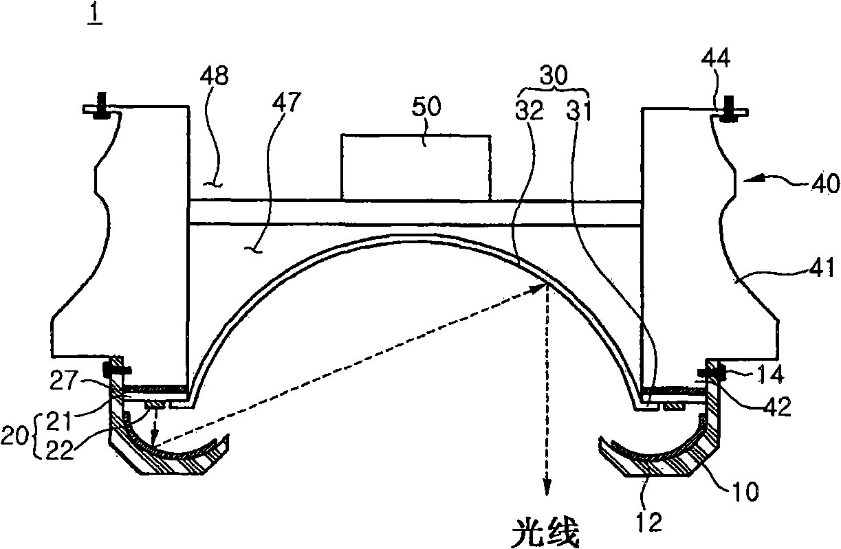
图3是图1的照明装置的横截面图。Fig. 3 is a cross-sectional view of the lighting device of Fig. 1 .
图4是示出图1的照明装置的热辐射主体的另一实施例的横截面图。FIG. 4 is a cross-sectional view illustrating another embodiment of a heat radiation body of the lighting device of FIG. 1 .
图5是示出图1的照明装置的发光模块单元的另一实施例的平面图。FIG. 5 is a plan view illustrating another embodiment of the light emitting module unit of the lighting device of FIG. 1 .
图6是根据第二实施例的照明装置的透视图。Fig. 6 is a perspective view of a lighting device according to a second embodiment.
图7是图6的照明装置的分解透视图。FIG. 7 is an exploded perspective view of the lighting device of FIG. 6 .
图8是示出图7的由“A”表示的区域的放大视图。FIG. 8 is an enlarged view showing an area indicated by 'A' of FIG. 7 .
图9是示出图6的照明装置的反射盖的各种示例的视图。FIG. 9 is views illustrating various examples of reflective covers of the lighting device of FIG. 6 .
图10是根据第三实施例的照明装置的横截面图。Fig. 10 is a cross-sectional view of a lighting device according to a third embodiment.
图11是根据第四实施例的照明装置的横截面图。Fig. 11 is a cross-sectional view of a lighting device according to a fourth embodiment.
具体实施方式Detailed ways
在下文中,将参考附图来详细描述本发明的实施例。Hereinafter, embodiments of the present invention will be described in detail with reference to the accompanying drawings.
应当理解,当一个元件被称为在另一元件“上”或“下”时,它可以直接位于该元件上/下,也可以存在有一个或多个中间元件。It will be understood that when an element is referred to as being "on" or "under" another element, it can be directly on/under the element, and one or more intervening elements may also be present.
图1是根据第一实施例的照明装置1的透视图。图2是照明装置1的分解透视图。图3是照明装置1的横截面图。Fig. 1 is a perspective view of a
参考图1至图3,根据第一实施例的照明装置1包括:热辐射主体40,该热辐射主体40包括形成在其底表面上的第一容纳凹槽47;反射结构30,该反射结构30布置在第一容纳凹槽47中;发光模块单元20,该发光模块单元20形成在热辐射主体40的底表面的周边上;以及反射盖10,该反射盖10形成在发光模块单元20下方并且将从发光模块单元20发射的光反射到反射结构30。Referring to FIGS. 1 to 3 , the
在热辐射主体40的顶表面上可以形成有第二容纳凹槽48。在该第二容纳凹槽48中可以布置有电源控制器50。该电源控制器50电连接到发光模块单元20,从而将电力和/或驱动信号提供给发光模块单元20。A second receiving
根据第一实施例的照明装置1附接或联接到诸如天花板或墙面等的外部支撑构件(未示出),从而提供光。这里,从发光模块单元20发射的光由反射盖10反射并且朝着反射结构30入射。朝着反射结构30入射的光再由反射结构30反射并提供到外部。即,根据第一实施例的照明装置1能够通过至少两次反射来提供眩光被减少的柔光。The
根据第一实施例的照明装置1能够通过两次反射来提供光,从而产生各种作用,例如,光催化反应和光的波长变化等。稍后将对其进行详细描述。The
在下文中,将详细描述根据第一实施例的照明装置1的部件和作用。Hereinafter, components and actions of the
热辐射主体40构成照明装置1的主体并且辐射从发光模块单元20产生的热量。The
热辐射主体40由具有高热辐射效率的金属材料或树脂材料制成。然而,热辐射主体40的材料不限于此。例如,热辐射主体40的材料可以包括Al、Ni、Cu、Ag以及Sn中的至少一个。The
在热辐射主体40的侧面可以形成有凸凹结构41,以通过扩大该热辐射主体40的表面积来使热辐射效率最大化。可以根据照明装置1的设计来不同地改变该凸凹结构41的形状。A convex-
第一容纳凹槽47形成在热辐射主体40的底表面上。第二容纳凹槽48形成在热辐射主体40的顶表面上。反射结构30可以插入并布置在第一容纳凹槽47中。电源控制器50可以布置在第二容纳凹槽48中。然而,并非必须形成该第二容纳凹槽48。The first receiving
从顶部看到的热辐射主体40的形状不限于圆形。热辐射主体40可以具有多边形形状、椭圆形形状等。The shape of the
热辐射主体40的上部区域可以包括紧固构件44,该紧固构件44能够联接到诸如天花板或墙面等的外部支撑构件(未示出)。例如,通过将联接螺钉插入到形成在紧固构件44中的孔内,热辐射主体40能够联接到该外部支撑构件(未示出)。The upper region of the
如图4所示,在热辐射主体40的上部分中形成有螺旋凹槽44b,从而该照明装置1可以旋转并固定到形成在所述外部支撑构件(未示出)中的联接凹槽。然而,用于将照明装置1附接或联接到该外部支撑构件(未示出)的方法不受限制。As shown in FIG. 4, a
在热辐射主体40的下部分中可以形成有错位部(level difference portion)42,以便将反射盖10联接到热辐射主体40。反射盖10可以借助于联接螺钉14等联接到该错位部42。然而,用于将反射盖10联接到热辐射主体40的方法不限于此。A
发光模块单元20形成在热辐射主体40的底表面的周边上。即,发光模块单元20形成在热辐射主体40的底表面的第一容纳凹槽47的外部。The light emitting
发光模块单元20可以包括基板21和安装在该基板21上的多个发光器件22。The light emitting
通过将电路图案印制在绝缘体上来制成该基板21。基板21可以包括如下项中的一种:印制电路板(PCB)、柔性PCB、金属芯PCB、陶瓷PCB以及由其它材料制成的PCB。The
基板21具有与热辐射主体40的形状相对应的形状。如图1和图2所示,如果从顶部看到的热辐射主体40的形状是圆形,则基板21的形状可以是圆环形。The
同时,当难以制造圆环形基板21a时,可以提供多个直线形基板21a,并且,如图5所示,所述多个直线形基板21a以接近于圆形的多边形环的形式相互联接。基板21的形状不限于此。Meanwhile, when it is difficult to manufacture the circular substrate 21a, a plurality of linear substrates 21a may be provided and, as shown in FIG. 5, coupled to each other in the form of a nearly circular polygonal ring. The shape of the
多个发光器件22中的每一个均可以包括至少一个发光二极管(在下文中称为LED)。LED可以发射紫外线(UV)光、红外线(IR)光以及包括红光、绿光、蓝光及白光等在内的可见光。然而,由LED发射的光的种类和数目不受限制。Each of the plurality of light emitting
同时,在发光模块单元20与热辐射主体40之间布置有热辐射板27。例如,在热辐射板27附接到热辐射主体40的底表面的周边上之后,发光模块单元20附接到热辐射板27。热辐射板27由导热带或导热粘合剂等形成。热辐射板27的材料不限于此。Meanwhile, a
反射结构30被部分插入并布置在形成于热辐射主体40的底表面上的第一容纳凹槽47中。反射结构30反射从反射盖10入射的光并将该光提供到外部。The
如图3所示,该反射结构30包括半球形反射表面32和位于该反射表面32周围的边缘31。As shown in FIG. 3 , the
例如,边缘31布置在发光模块单元20的基板21下方并且利用粘合剂或联接螺钉联接到基板21。反射表面32被部分嵌入并布置在第一容纳凹槽47中。For example, the
同时,反射结构30的反射表面32的形状不限于半球形。例如,反射表面32可以具有顶点凹陷的半球形形状,即抛物线形状,其具有带两个抛物面的部分。可以根据照明装置1的设计来改变该反射表面32的形状。Meanwhile, the shape of the
反射结构30的材料可以包括具有高反射效率的金属材料或树脂材料,或者可以由该金属材料或树脂材料形成。例如,该金属材料可以包括如下项中的至少一种:Ag、含有Ag的合金、Al、含有Al的合金。该树脂材料包括PET树脂、PC树脂、PVC树脂等。The material of the
反射结构30的表面可以涂覆有具有高反射效率的白色光致阻焊剂(PSR)、Ag、Al等。The surface of the
或者,在未形成有反射结构30的情况下,第一容纳凹槽47可形成为具有反射表面,该反射表面具有半球形等形状并具有高反射效率。反射结构30的种类不限于此。Alternatively, in the case where the
反射盖10形成在发光模块单元20下方并将从发光模块单元20发射的光反射到反射结构30。反射盖10可以包括开口15,该开口15用于允许从反射结构30反射的光被发射到外部。The
反射盖10的内表面可以是弯曲的,从而通过调节从发光模块单元20发射的光的取向角来将光反射并发射到反射结构30。可以根据照明装置1的设计来不同地确定该内表面的曲面曲率。同时,反射盖10的内表面可以具有多边形形状。该内表面的形状不限于此。The inner surface of the
如图3所示,例如,借助于联接螺钉14等,能够将反射盖10联接到形成在热辐射主体40的下部分中的错位部42。然而,用于将反射盖10联接到热辐射主体40的方法不受限制。As shown in FIG. 3 , for example, by means of coupling screws 14 or the like, it is possible to couple the
反射盖10可以包括具有高反射效率的金属材料或树脂材料,或者可以由该金属材料或树脂材料形成。例如,该金属材料可以包括如下项中的至少一种:Ag、含有Ag的合金、Al、含有Al的合金。该树脂材料包括PET树脂、PC树脂、PVC树脂等。The
反射盖10的表面可以涂覆有具有高反射效率的白色光致阻焊剂(PSR)、Ag、Al等。The surface of the
这样,由于从发光模块单元20发射的光通过反射盖10和反射结构30反射并发射到外部,所以该照明装置1能够提供眩光被减少的柔光。As such, since the light emitted from the light emitting
同时,在反射盖10的内表面上可以形成有光催化材料12和荧光材料中的至少一种。结果,提供了从发光模块单元20发射的光,以实现各种功能,例如,通过形成在反射盖10的内表面上的光催化材料12和/或荧光材料来防污染。在下文中,稍后将对其进行详细描述。Meanwhile, at least one of a
例如,光催化材料12可以包括氧化钛(TiO2)。氧化钛(TiO2)通过借助于具有大约200nm至450nm的蓝光波长或紫外线波长的光引起化学反应来氧化、分解并去除杂质。For example,
换言之,光催化材料12形成在反射盖10的内表面上并且防止反射盖10被杂质污染,从而能够保持该照明装置1的光强度。In other words, the
发光模块单元20的多个发光器件22发射具有紫外线波长的光(氧化钛(TiO2)通过该光来引起化学反应),或者发射具有大约200nm至450nm的蓝光波长的光。这里,当使用氧化钛(TiO2)作为光催化材料12时,希望所述多个发光器件22的至少一部分被使用。The plurality of light emitting
光催化材料12能以薄膜的形式涂覆或喷涂在反射盖10的内表面上。然而,用于形成光催化材料12的方法不受限制。The
通过从发光模块单元20发射的第一光来激励该荧光材料,从而产生第二光。因此,通过该荧光材料产生由该第一光和第二光混合而成的光。结果,能够改变由照明装置1提供的光的波长。The fluorescent material is excited by the first light emitted from the light emitting
该荧光材料被包括在树脂材料或硅材料中,并且利用涂覆法等形成在反射盖10的内表面上。另一方面,设置有包括该荧光材料的磷发光膜(PLF),然后,该磷发光膜(PLF)可以附接到反射盖10的内表面。用于形成该荧光材料的方法不受限制。The fluorescent material is included in a resin material or a silicon material, and is formed on the inner surface of the
电源控制器50布置在热辐射主体40的顶表面的第二容纳凹槽48中。The
电源控制器50接收来自外部电源的电力并将该电力转换为适合于发光模块单元20的类型的电力并然后输送。例如,电源控制器50可以形成为包括从由如下项组成的组中选择的至少一个:将交流转换为直流的交流-直流转换器,用于保护发光模块单元20的静电放电(ESD)的保护装置,用于控制和驱动该发光模块单元20的驱动芯片,以及微处理器等。The
虽然未示出,但电源控制器50能够通过布线而电连接到发光模块单元20。例如,可形成有通孔,该通孔贯穿热辐射主体40的顶表面和底表面,然后所述布线能够通过该通孔将发光模块单元20连接到电源控制器50。Although not shown, the
在下文中,将详细描述根据第二实施例的照明装置1B。然而,在第二实施例的描述中,将会省略或简要地描述与第一实施例重复的描述。Hereinafter, the lighting device 1B according to the second embodiment will be described in detail. However, in the description of the second embodiment, the description overlapping with the first embodiment will be omitted or briefly described.
图6是根据第二实施例的照明装置1B的透视图。图7是图6的照明装置1B的分解透视图。图8是图7的由“A”表示的区域的放大视图。Fig. 6 is a perspective view of a lighting device 1B according to the second embodiment. FIG. 7 is an exploded perspective view of the lighting device 1B of FIG. 6 . FIG. 8 is an enlarged view of the area indicated by "A" of FIG. 7 .
参考图6至图8,照明装置1B包括:热辐射主体40,该热辐射主体40包括形成在其底表面上的第一容纳凹槽47;反射结构30,该反射结构30布置在第一容纳凹槽47中并且将入射光反射到外部;发光模块单元20,该发光模块单元20形成在热辐射主体40的底表面的周边上;以及反射盖10,该反射盖10形成在发光模块单元20下方并且包括多个透镜11b,所述多个透镜11b将从发光模块单元20发射的光反射到反射结构30。Referring to FIG. 6 to FIG. 8 , the lighting device 1B includes: a
除了反射盖10b的形状之外,根据第二实施例的照明装置1B与根据第一实施例的照明装置1类似。The lighting device 1B according to the second embodiment is similar to the
反射盖10b可以具有圆形形状或多边环形形状。反射盖10b的内表面包括多个凹形表面。所述多个凹形表面以规则的间隔、呈放射状地布置在反射盖10b的内表面上。需要有至少一个凹形表面。该凹形表面可以具有恒定曲率或具有多边形形状。该凹形表面具有如下功能:充分收集沿特定方向从发光模块单元发射的光。The
因此,在本实施例中,该凹形表面被指定为透镜11b。Therefore, in this embodiment, this concave surface is designated as
多个透镜11b可以具有能够将从发光模块单元20入射的光有效反射到反射结构30的形状,例如,具有切除部的半球形形状。透镜11b的形状不受限制。The plurality of
反射盖10b的多个透镜11b可以形成为与发光模块单元20的多个发光器件22相对应。因此,所述多个透镜11b能够设计成使得从多个发光器件22中的每一个发光器件发射的光朝向反射结构30行进。The plurality of
这里,所述多个透镜11b可以与所述多个发光器件22具有一一对应关系或者一对多对应关系。同时,可以根据由照明装置1B提供的照明来改变所述多个透镜11b与多个发光器件22之间的对应比率。该对应比率不受限制。Here, the plurality of
特别地,当所述多个发光器件22发射具有多种颜色的光时,就要求所述多个透镜11b与所述多个发光器件22具有一对多对应关系。In particular, when the plurality of light emitting
例如,分别发射红光、绿光以及蓝光的多个发光器件可以对应于一个透镜11b。或者,发射可见光的发光器件以及随后的发射能够与光催化材料进行反应的紫外线光的发光器件可以对应于一个透镜11b。这些发光器件与透镜11b之间进行对应的方法不受限制。For example, a plurality of light emitting devices respectively emitting red light, green light, and blue light may correspond to one
图9是示出包括多个透镜11b的反射盖10b的形状的各种示例的视图。FIG. 9 is a view showing various examples of the shape of the
参考图9的(a),反射盖10b的内表面和外表面可以是弯曲的。参考图9的(b),反射盖10b的内表面和外表面可以具有多边形表面。参考图9的(c),反射盖10b的内表面可以是弯曲的,而反射盖10b的外表面可以是平的。Referring to (a) of FIG. 9 , inner and outer surfaces of the
即,根据照明装置1B的设计,能够不同地改变包括多个透镜11b的反射盖10b的形状。That is, depending on the design of the lighting device 1B, the shape of the
再次参考图6至图8,在所述多个透镜11b的内表面上可以形成有光催化材料12b和荧光材料中的至少一种。光催化材料12b与从发光模块单元20发射的光进行反应并分解杂质,然后,由此防止反射盖10b被污染并保持该照明装置1B的光强度。通过从发光模块单元20发射的第一光来激励该荧光材料,因此产生第二光。因此,照明装置1B能够提供具有通过混合该第一光和第二光而改变的波长的光。Referring to FIGS. 6 to 8 again, at least one of a
虽然未示出,但还可以在反射盖10b下方形成有分隔盖,以保护包括多个透镜11b的反射盖10b。这里,该分隔盖不受限制。Although not shown, a partition cover may be further formed under the
在下文中,将详细描述根据第三实施例的照明装置1C。然而,在第三实施例的描述中,将会省略或简要地描述与第一实施例重复的描述。Hereinafter, the
图10是根据第三实施例的照明装置1C的横截面图。Fig. 10 is a cross-sectional view of a
参考图10,照明装置1C包括:热辐射主体40,该热辐射主体40包括形成在其底表面上的第一容纳凹槽47;反射结构30,该反射结构30布置在第一容纳凹槽47中并将入射光反射到外部,并且在反射结构30的内表面中包括磷发光膜(PLF);发光模块单元20,该发光模块单元20形成在热辐射主体40的底表面的周边上;以及反射盖10,该反射盖10形成在发光模块单元20下方并将从发光模块单元20发射的光发射到反射结构30。Referring to FIG. 10 , the
除了在反射结构30的内表面上存在有磷发光膜(PLF)35之外,根据第三实施例的照明装置1C与根据第一实施例的照明装置1相同。The
磷发光膜(PLF)35是包括荧光材料的由硅或树脂制成的薄膜。该荧光材料由入射在反射结构30上的第一光来激励并产生第二光。反射结构30能够发射由该第一光和第二光混合而成的光。The phosphorescent film (PLF) 35 is a thin film made of silicon or resin including a fluorescent material. The fluorescent material is excited by the first light incident on the
即,通过附接到反射结构30的内表面的磷发光膜(PLF)35,可以改变从反射盖10入射的光的波长。结果,照明装置1C能够呈现各种色感。That is, the wavelength of light incident from the
同时,在第三实施例中,虽然反射结构30和磷发光膜(PLF)35分开布置,但反射结构30可以具有其自己的磷发光功能,而非在反射结构30的内表面上布置单独的磷发光膜(PLF)。即,在本实施例中,能够用具有由硬质材料制成的平板形状的磷发光板来代替反射结构30,代替磷发光膜(PLF)35。因此,从发光模块单元20发射的光由反射盖10发射并入射在反射结构30上,然后该入射光被再反射并发射到外部。这里,从反射盖10入射的光具有被改变的波长并发射到外部。Meanwhile, in the third embodiment, although the
在下文中,将详细描述根据第四实施例的照明装置1D。然而,在第四实施例的描述中,将会省略或简要地描述与第一实施例重复的描述。Hereinafter, the lighting device 1D according to the fourth embodiment will be described in detail. However, in the description of the fourth embodiment, the description overlapping with the first embodiment will be omitted or briefly described.
图11是根据第四实施例的照明装置1D的横截面图。Fig. 11 is a cross-sectional view of a lighting device 1D according to a fourth embodiment.
参考图11,照明装置1D包括:热辐射主体40,该热辐射主体40包括形成在其底表面上的第一容纳凹槽47;反射结构30,该反射结构30布置在第一容纳凹槽47中;反射盖10,该反射盖10形成在热辐射主体40的底表面的周边上,并且该该反射盖10内包括内凹槽17;以及发光模块单元20,该发光模块单元20布置在反射盖10的内凹槽17内并将光发射到该内凹槽17的侧壁。Referring to FIG. 11 , the lighting device 1D includes: a
除了反射盖10的形状以及发光模块单元20所形成的位置之外,根据第四实施例的照明装置1D与根据第一实施例的照明装置1相同。The lighting device 1D according to the fourth embodiment is the same as the
反射盖10内包括内凹槽17。发光模块单元20形成在内凹槽17的下部分中。这里,发光模块单元20将光发射到内凹槽17的侧壁。然后,由该侧壁反射的光能够入射到反射结构30。The reflection cover 10 includes an inner groove 17 . The light emitting
即,通过在侧向方向上发光而不是如第一实施例中描述的向下发光,照明装置1D的发光模块单元20能够具有与第一实施例相同的效果。That is, the light emitting
在上述实施例中描述的特征、结构和效果等被包括在本发明的至少一个实施例中,并且不必局限于一个实施例。此外,这些实施例所属领域的技术人员能够在其它的实施例中组合或修改在各个实施例中提供的特征、结构和效果等。因此,与该组合和修改有关的内容应当解释为包括在本发明的范围内。The features, structures, effects, etc. described in the above embodiments are included in at least one embodiment of the present invention, and are not necessarily limited to one embodiment. In addition, those skilled in the art to which these embodiments belong can combine or modify the features, structures, effects, etc. provided in each embodiment in other embodiments. Therefore, the contents related to the combination and modification should be construed as being included in the scope of the present invention.
尽管在上文描述了本发明的多个实施例,但这些仅是示例,并非限制本发明。此外,在不脱离本发明的必要技术特征的情况下,本领域的技术人员能以各种方式改变和修改本发明。例如,可以修改在本发明的实施例中详细描述的部件。此外,由于修改和应用而引起的区别应当解释为包括在所附权利要求中描述的本发明的精神和范围内。While various embodiments of the invention have been described above, these are examples only, and do not limit the invention. In addition, those skilled in the art can change and modify the present invention in various ways without departing from the essential technical characteristics of the present invention. For example, components described in detail in the embodiments of the present invention may be modified. Furthermore, differences due to modifications and applications should be construed as being included within the spirit and scope of the present invention described in the appended claims.
Claims (20)
Applications Claiming Priority (6)
| Application Number | Priority Date | Filing Date | Title |
|---|---|---|---|
| KR1020090107487A KR101144453B1 (en) | 2009-11-09 | 2009-11-09 | Lighting device |
| KR10-2009-0107487 | 2009-11-09 | ||
| KR1020090107489A KR101072220B1 (en) | 2009-11-09 | 2009-11-09 | Lighting device |
| KR10-2009-0107489 | 2009-11-09 | ||
| KR1020090107492A KR101114095B1 (en) | 2009-11-09 | 2009-11-09 | Lighting device |
| KR10-2009-0107492 | 2009-11-09 |
Publications (2)
| Publication Number | Publication Date |
|---|---|
| CN102072425A true CN102072425A (en) | 2011-05-25 |
| CN102072425B CN102072425B (en) | 2013-07-17 |
Family
ID=43558081
Family Applications (1)
| Application Number | Title | Priority Date | Filing Date |
|---|---|---|---|
| CN201010543783XA Expired - Fee Related CN102072425B (en) | 2009-11-09 | 2010-11-09 | Lighting device |
Country Status (3)
| Country | Link |
|---|---|
| US (2) | US8573802B2 (en) |
| EP (2) | EP2320128B1 (en) |
| CN (1) | CN102072425B (en) |
Cited By (1)
| Publication number | Priority date | Publication date | Assignee | Title |
|---|---|---|---|---|
| CN104676315A (en) * | 2014-09-02 | 2015-06-03 | 周焕球 | Internal reflection lamp |
Families Citing this family (33)
| Publication number | Priority date | Publication date | Assignee | Title |
|---|---|---|---|---|
| US20110110095A1 (en) * | 2009-10-09 | 2011-05-12 | Intematix Corporation | Solid-state lamps with passive cooling |
| US8613528B2 (en) * | 2010-05-07 | 2013-12-24 | Abl Ip Holding Llc | Light fixtures comprising an enclosure and a heat sink |
| CN102777777B (en) * | 2011-05-12 | 2016-03-30 | 欧司朗股份有限公司 | Lighting device and there is the illuminator of this lighting device |
| US8568000B2 (en) * | 2011-08-29 | 2013-10-29 | Tai-Her Yang | Annular-arranged lamp capable of backward projecting by concave sphere |
| KR101326518B1 (en) | 2011-09-02 | 2013-11-07 | 엘지이노텍 주식회사 | Lighting device |
| TWM422646U (en) * | 2011-09-07 | 2012-02-11 | Shi-Ming Chen | Structure of lamp base |
| US8992051B2 (en) | 2011-10-06 | 2015-03-31 | Intematix Corporation | Solid-state lamps with improved radial emission and thermal performance |
| US20130088848A1 (en) | 2011-10-06 | 2013-04-11 | Intematix Corporation | Solid-state lamps with improved radial emission and thermal performance |
| WO2013052749A2 (en) * | 2011-10-06 | 2013-04-11 | Intematix Corporation | Solid-state lamps with improved radial emission and thermal performance |
| KR102017538B1 (en) | 2012-01-31 | 2019-10-21 | 엘지이노텍 주식회사 | Lighting device |
| DE102012003071B4 (en) * | 2012-02-10 | 2014-11-20 | Alfred-Wegener-Institut Helmholtz-Zentrum für Polar- und Meeresforschung | reflector spotlight |
| DE102012206397B4 (en) | 2012-04-18 | 2021-04-15 | Osram Gmbh | Lighting device with a screen, one side of which is irradiated by a first light source via a reflector and the other side, which is coated with a luminescent material, is irradiated by a second light source |
| US8680755B2 (en) | 2012-05-07 | 2014-03-25 | Lg Innotek Co., Ltd. | Lighting device having reflectors for indirect light emission |
| US9495660B2 (en) | 2013-07-31 | 2016-11-15 | Google Inc. | Inferring social groups through patterns of communication |
| USD748840S1 (en) * | 2014-05-27 | 2016-02-02 | Lumens Co., Ltd | Ceiling light fixture |
| USD767815S1 (en) * | 2014-05-27 | 2016-09-27 | Lumens Co., Ltd. | Ceiling light fixture |
| DE202014103605U1 (en) * | 2014-08-04 | 2014-08-21 | Brillant Ag | Electric light |
| USD769516S1 (en) * | 2014-08-04 | 2016-10-18 | Spring City Electrical Mfg. Co. | Center mount lamp support |
| US9285100B2 (en) * | 2014-08-11 | 2016-03-15 | Min Hsiang Corporation | Lens structure for a vehicular lamp |
| US9702539B2 (en) | 2014-10-21 | 2017-07-11 | Cooper Technologies Company | Flow-through luminaire |
| KR101601531B1 (en) * | 2014-11-07 | 2016-03-10 | 주식회사 지엘비젼 | Lighting Device |
| US10100984B2 (en) * | 2015-10-15 | 2018-10-16 | GE Lighting Solutions, LLC | Indirect light mixing LED module for point-source applications |
| US20170108177A1 (en) * | 2015-10-15 | 2017-04-20 | GE Lighting Solutions, LLC | Indirect color-mixing led module for point-source source application |
| DE102016002849A1 (en) * | 2016-03-10 | 2017-09-14 | Selux Aktiengesellschaft | Also down radiating lamp element for a street lighting or street lamp with an annular, downward radiating light source |
| ITUA20162784A1 (en) * | 2016-04-21 | 2017-10-21 | Efore S P A | LED SPOTLIGHT |
| USD847399S1 (en) | 2017-05-05 | 2019-04-30 | Hubbell Incorporated | Performance high-bay luminaire |
| USD930219S1 (en) * | 2017-05-16 | 2021-09-07 | Olympia Lighting, Inc. | Light fixture |
| EP3431868A1 (en) * | 2017-07-21 | 2019-01-23 | Philips Lighting Holding B.V. | Catadioptric lighting device |
| US10928020B1 (en) * | 2019-08-22 | 2021-02-23 | Usg Interiors, Llc | Light bar for suspended ceiling |
| LU102029B1 (en) * | 2020-09-02 | 2022-03-02 | Bega Gantenbrink Leuchten Kg | Luminaire for generating direct and indirect lighting |
| EP4215802A4 (en) * | 2020-09-21 | 2024-11-13 | Suzhou Opple Lighting Co., Ltd. | LIGHT SOURCE SYSTEM OF A LUMINAIRE AND LUMINAIRE |
| US12007102B2 (en) * | 2022-03-16 | 2024-06-11 | Globe Electric Company Inc. | Trimless recessed light fixture |
| US11879629B2 (en) * | 2022-03-31 | 2024-01-23 | RAB Lighting Inc. | LED light fixture with a heat sink having concentrically segmented fins |
Citations (4)
| Publication number | Priority date | Publication date | Assignee | Title |
|---|---|---|---|---|
| JPH0581913A (en) * | 1991-09-24 | 1993-04-02 | Toshiba Lighting & Technol Corp | Lighting device |
| JP2001243821A (en) * | 2000-02-28 | 2001-09-07 | Mitsubishi Electric Lighting Corp | Surface-emitting LED light source |
| CN1762061A (en) * | 2003-12-05 | 2006-04-19 | 三菱电机株式会社 | Light-emitting device and lighting fixture using the light-emitting device |
| JP2006179658A (en) * | 2004-12-22 | 2006-07-06 | Mitsubishi Electric Corp | Light emitting device |
Family Cites Families (41)
| Publication number | Priority date | Publication date | Assignee | Title |
|---|---|---|---|---|
| GB1138878A (en) * | 1966-09-09 | 1969-01-01 | British Lighting Ind Ltd | Artificial sun-bathing enclosure |
| US4755916A (en) * | 1981-07-23 | 1988-07-05 | Collins Dynamics | Combined flood and spot light |
| US4591960A (en) * | 1984-10-02 | 1986-05-27 | Mwc Lighting | Lighting optical system |
| DE3929955A1 (en) * | 1989-09-08 | 1991-03-14 | Inotec Gmbh Ges Fuer Innovativ | LIGHT SPOTLIGHTS |
| WO1992019911A1 (en) * | 1991-05-02 | 1992-11-12 | Ruud Lighting, Inc. | Improved bollard luminaire |
| IT1252026B (en) * | 1991-11-29 | 1995-05-27 | LIGHTING APPARATUS IN PARTICULAR FOR ENVIRONMENTS WITHOUT NATURAL LIGHT | |
| US5488550A (en) * | 1992-11-18 | 1996-01-30 | Yang; Jerry S. C. | Multi purpose lamp |
| US5564065A (en) * | 1995-01-19 | 1996-10-08 | Chelsea Group Ltd. | Carbon monoxide air filter |
| DE29620583U1 (en) * | 1996-11-27 | 1997-02-13 | Kundisch Microtech GmbH & Co. KG, 78056 Villingen-Schwenningen | Lighting fixture with continuously adjustable color change of the light and the light cone |
| US6186649B1 (en) * | 1998-04-16 | 2001-02-13 | Honeywell International Inc. | Linear illumination sources and systems |
| US6149283A (en) * | 1998-12-09 | 2000-11-21 | Rensselaer Polytechnic Institute (Rpi) | LED lamp with reflector and multicolor adjuster |
| US6425677B1 (en) * | 2001-02-20 | 2002-07-30 | Prokia Technology Co., Ltd. | Illuminating apparatus using multiple light sources |
| US6655813B1 (en) * | 2002-01-07 | 2003-12-02 | Genlyte Thomas Group Llc | Multi-function luminaire |
| KR100804653B1 (en) * | 2003-06-16 | 2008-02-20 | 미쓰비시덴키 가부시키가이샤 | Surface light source device and display device using this device |
| US7246917B2 (en) * | 2003-08-12 | 2007-07-24 | Illumination Management Solutions, Inc. | Apparatus and method for using emitting diodes (LED) in a side-emitting device |
| TWI233475B (en) * | 2004-01-20 | 2005-06-01 | Jau-Tang Lin | Lighting device with increased brightness |
| IES20050086A2 (en) * | 2004-02-17 | 2005-09-21 | William M Kelly | A utility lamp |
| JP2005243973A (en) * | 2004-02-26 | 2005-09-08 | Kyocera Corp | Light emitting device and lighting device |
| US7144131B2 (en) * | 2004-09-29 | 2006-12-05 | Advanced Optical Technologies, Llc | Optical system using LED coupled with phosphor-doped reflective materials |
| US7559664B1 (en) * | 2004-12-27 | 2009-07-14 | John V. Walleman | Low profile backlighting using LEDs |
| JP4944948B2 (en) * | 2006-05-05 | 2012-06-06 | クリー インコーポレイテッド | Lighting device |
| US7703945B2 (en) * | 2006-06-27 | 2010-04-27 | Cree, Inc. | Efficient emitting LED package and method for efficiently emitting light |
| DE102006037376A1 (en) * | 2006-08-09 | 2008-02-14 | Patent-Treuhand-Gesellschaft für elektrische Glühlampen mbH | lamp |
| US7396146B2 (en) * | 2006-08-09 | 2008-07-08 | Augux Co., Ltd. | Heat dissipating LED signal lamp source structure |
| DE102006044019B4 (en) * | 2006-09-15 | 2011-12-29 | Stiftung Alfred-Wegener-Institut für Polar- und Meeresforschung Stiftung des öffentlichen Rechts | reflector spotlight |
| EP2074655B1 (en) * | 2006-10-12 | 2016-04-13 | Panasonic Intellectual Property Management Co., Ltd. | Light-emitting apparatus |
| JP2008135219A (en) * | 2006-11-27 | 2008-06-12 | Phoenix Denki Kk | Luminaire |
| US8596841B2 (en) * | 2006-12-19 | 2013-12-03 | Koito Manufacturing Co., Ltd. | Vehicle lamp |
| US20080198572A1 (en) * | 2007-02-21 | 2008-08-21 | Medendorp Nicholas W | LED lighting systems including luminescent layers on remote reflectors |
| US8403531B2 (en) * | 2007-05-30 | 2013-03-26 | Cree, Inc. | Lighting device and method of lighting |
| US7686486B2 (en) * | 2007-06-30 | 2010-03-30 | Osram Sylvania Inc. | LED lamp module |
| JP5077543B2 (en) * | 2007-09-07 | 2012-11-21 | スタンレー電気株式会社 | Vehicle lamp unit |
| KR20090046120A (en) * | 2007-11-05 | 2009-05-11 | 현대자동차주식회사 | LED lighting device |
| US7722222B2 (en) * | 2008-03-24 | 2010-05-25 | Fu Zhun Precision Industry (Shen Zhen) Co., Ltd. | LED lamp assembly |
| US8028537B2 (en) * | 2009-05-01 | 2011-10-04 | Abl Ip Holding Llc | Heat sinking and flexible circuit board, for solid state light fixture utilizing an optical cavity |
| CN101603662A (en) * | 2008-06-13 | 2009-12-16 | 富准精密工业(深圳)有限公司 | Led lamp and lampshade thereof |
| US8142057B2 (en) * | 2009-05-19 | 2012-03-27 | Schneider Electric USA, Inc. | Recessed LED downlight |
| KR20090066262A (en) | 2009-06-03 | 2009-06-23 | 최재민 | LED lamp |
| US20110033346A1 (en) * | 2009-08-04 | 2011-02-10 | Bohlen Johns R | Air cleaner with photo-catalytic oxidizer |
| DE102009042338B4 (en) * | 2009-09-21 | 2019-03-21 | Berchtold Holding Gmbh | surgical light |
| KR101824039B1 (en) * | 2011-07-29 | 2018-01-31 | 엘지이노텍 주식회사 | display apparatus |
-
2010
- 2010-10-20 EP EP10188261.1A patent/EP2320128B1/en not_active Not-in-force
- 2010-10-20 EP EP15151194.6A patent/EP2863117B1/en not_active Not-in-force
- 2010-11-04 US US12/939,559 patent/US8573802B2/en not_active Expired - Fee Related
- 2010-11-09 CN CN201010543783XA patent/CN102072425B/en not_active Expired - Fee Related
-
2013
- 2013-10-08 US US14/049,015 patent/US9200761B2/en not_active Expired - Fee Related
Patent Citations (5)
| Publication number | Priority date | Publication date | Assignee | Title |
|---|---|---|---|---|
| JPH0581913A (en) * | 1991-09-24 | 1993-04-02 | Toshiba Lighting & Technol Corp | Lighting device |
| JP2001243821A (en) * | 2000-02-28 | 2001-09-07 | Mitsubishi Electric Lighting Corp | Surface-emitting LED light source |
| CN1762061A (en) * | 2003-12-05 | 2006-04-19 | 三菱电机株式会社 | Light-emitting device and lighting fixture using the light-emitting device |
| CN101363578A (en) * | 2003-12-05 | 2009-02-11 | 三菱电机株式会社 | light emitting device |
| JP2006179658A (en) * | 2004-12-22 | 2006-07-06 | Mitsubishi Electric Corp | Light emitting device |
Cited By (1)
| Publication number | Priority date | Publication date | Assignee | Title |
|---|---|---|---|---|
| CN104676315A (en) * | 2014-09-02 | 2015-06-03 | 周焕球 | Internal reflection lamp |
Also Published As
| Publication number | Publication date |
|---|---|
| US20110110096A1 (en) | 2011-05-12 |
| EP2320128A3 (en) | 2013-01-02 |
| CN102072425B (en) | 2013-07-17 |
| EP2863117A2 (en) | 2015-04-22 |
| EP2320128A2 (en) | 2011-05-11 |
| EP2320128B1 (en) | 2015-02-25 |
| EP2863117B1 (en) | 2016-07-13 |
| US9200761B2 (en) | 2015-12-01 |
| US20140036509A1 (en) | 2014-02-06 |
| EP2863117A3 (en) | 2015-06-10 |
| US8573802B2 (en) | 2013-11-05 |
Similar Documents
| Publication | Publication Date | Title |
|---|---|---|
| CN102072425B (en) | Lighting device | |
| US9651223B2 (en) | Light-emitting apparatus with fastening of optical component to pedestal through light-emitting substrate through-hole, illumination light source having the same, and lighting apparatus having the same | |
| CN202884522U (en) | Light-emitting device and lighting appliance | |
| KR101388876B1 (en) | Lighting fixture | |
| US20140204594A1 (en) | Illumination light source and lighting apparatus | |
| EP4004988B1 (en) | Led lamp | |
| CN102449386A (en) | Reflector systems for lighting installations | |
| CN102444816A (en) | Flat modulus light source | |
| JP6217972B2 (en) | lighting equipment | |
| JP2016170912A (en) | Luminaire | |
| US20130051061A1 (en) | Illumination device | |
| US20170077172A1 (en) | Light-emitting device and illumination light source | |
| JP6956110B2 (en) | Lighting device | |
| TW201312041A (en) | Illuminating device and lighting device | |
| KR101072220B1 (en) | Lighting device | |
| JP7591851B2 (en) | Lighting fixture and light diffusion cover used therewith | |
| KR101114095B1 (en) | Lighting device | |
| JP2014220160A (en) | Light source for illumination and lighting device | |
| KR101144453B1 (en) | Lighting device | |
| KR20170124271A (en) | Lighting device | |
| JP2016167432A (en) | Lighting device | |
| CN204494239U (en) | lighting equipment | |
| KR20190030668A (en) | Lighting device | |
| WO2021020096A1 (en) | Illumination device |
Legal Events
| Date | Code | Title | Description |
|---|---|---|---|
| C06 | Publication | ||
| PB01 | Publication | ||
| C10 | Entry into substantive examination | ||
| SE01 | Entry into force of request for substantive examination | ||
| C14 | Grant of patent or utility model | ||
| GR01 | Patent grant | ||
| CF01 | Termination of patent right due to non-payment of annual fee |
Granted publication date: 20130717 Termination date: 20191109 |
|
| CF01 | Termination of patent right due to non-payment of annual fee |