CN102134792B - Textile equipment for yarn finishing and yarn finishing method - Google Patents
Textile equipment for yarn finishing and yarn finishing method Download PDFInfo
- Publication number
- CN102134792B CN102134792B CN2011100212603A CN201110021260A CN102134792B CN 102134792 B CN102134792 B CN 102134792B CN 2011100212603 A CN2011100212603 A CN 2011100212603A CN 201110021260 A CN201110021260 A CN 201110021260A CN 102134792 B CN102134792 B CN 102134792B
- Authority
- CN
- China
- Prior art keywords
- yarn
- liquid
- liquid bar
- work nest
- fluid infusion
- Prior art date
- Legal status (The legal status is an assumption and is not a legal conclusion. Google has not performed a legal analysis and makes no representation as to the accuracy of the status listed.)
- Active
Links
- 238000000034 method Methods 0.000 title claims abstract description 19
- 239000004753 textile Substances 0.000 title abstract description 7
- 239000007788 liquid Substances 0.000 claims abstract description 82
- 238000012544 monitoring process Methods 0.000 claims abstract description 10
- 239000012530 fluid Substances 0.000 claims description 40
- 238000001802 infusion Methods 0.000 claims description 29
- 238000009941 weaving Methods 0.000 claims description 22
- 239000000284 extract Substances 0.000 claims description 20
- 238000002803 maceration Methods 0.000 claims description 20
- 230000000903 blocking effect Effects 0.000 claims description 17
- 238000006243 chemical reaction Methods 0.000 claims description 11
- 238000013461 design Methods 0.000 claims description 6
- 238000004804 winding Methods 0.000 claims description 3
- 238000007654 immersion Methods 0.000 abstract 6
- 238000009776 industrial production Methods 0.000 abstract 1
- 239000004744 fabric Substances 0.000 description 5
- 238000004519 manufacturing process Methods 0.000 description 5
- 239000000835 fiber Substances 0.000 description 4
- 239000003795 chemical substances by application Substances 0.000 description 3
- 238000004043 dyeing Methods 0.000 description 3
- 238000005516 engineering process Methods 0.000 description 3
- 230000001105 regulatory effect Effects 0.000 description 3
- 238000007598 dipping method Methods 0.000 description 2
- 239000000853 adhesive Substances 0.000 description 1
- 230000001070 adhesive effect Effects 0.000 description 1
- 239000011324 bead Substances 0.000 description 1
- 238000011161 development Methods 0.000 description 1
- 230000000694 effects Effects 0.000 description 1
- 238000007730 finishing process Methods 0.000 description 1
- 230000008771 sex reversal Effects 0.000 description 1
Images
Classifications
-
- Y—GENERAL TAGGING OF NEW TECHNOLOGICAL DEVELOPMENTS; GENERAL TAGGING OF CROSS-SECTIONAL TECHNOLOGIES SPANNING OVER SEVERAL SECTIONS OF THE IPC; TECHNICAL SUBJECTS COVERED BY FORMER USPC CROSS-REFERENCE ART COLLECTIONS [XRACs] AND DIGESTS
- Y02—TECHNOLOGIES OR APPLICATIONS FOR MITIGATION OR ADAPTATION AGAINST CLIMATE CHANGE
- Y02P—CLIMATE CHANGE MITIGATION TECHNOLOGIES IN THE PRODUCTION OR PROCESSING OF GOODS
- Y02P70/00—Climate change mitigation technologies in the production process for final industrial or consumer products
- Y02P70/50—Manufacturing or production processes characterised by the final manufactured product
- Y02P70/62—Manufacturing or production processes characterised by the final manufactured product related technologies for production or treatment of textile or flexible materials or products thereof, including footwear
Landscapes
- Treatment Of Fiber Materials (AREA)
Abstract
The invention provides textile equipment for yarn finishing and a yarn finishing method. The textile equipment comprises a working tank, a liquid supply tank used for supplying immersion liquid and monitoring the temperature of the immersion liquid, a servo motor air-pressure linkage device used for controlling the immersion time of the yarn, and a variable frequency system, wherein the upper end of the working tank is provided with a liquid backflow opening, while the lower end is provided with a circulating pump system communicated with the liquid supply tank; a yarn tension bracket is arranged above the opening; and the liquid supply tank is internally provided with a liquid level controller used for monitoring the liquid level, a temperature controller used for controlling the temperature of the liquid, a liquid supply device used for supplying immersion liquid, and a circulating system used for circulating the immersion liquid in the working tank and the liquid supply tank. In the method, through the control on the servo motor and the variable frequency system, different styles of finished yarns can be obtained. The utility model can meet the requirements for the immersion finishing of reeled yarns and single yarns in any length, and can finish the yarns very uniformly or in a non-uniform manner, simultaneously conduct continuous operation and meet the requirement for industrial production.
Description
Technical field
The present invention relates to textile technology field, be specifically related to a kind of Weaving device for yarn finish and yarn finish method.
Background technology
Along with the progress in epoch and improving constantly of living standard, people to the requirement of taking textiles by traditional attractive in appearance, comfortable to functional, characteristic sex reversal.The development of modern textile, dyeing and finishing process technology then provides possibility for satisfying this requirement.But now most of characteristics and functional textiles all obtain by fiber or cloth are put in order on the market, what use all is the equipment that pads of some routines, fiber after the arrangement or fabric difficulty aspect the fabric exploitation of postorder is larger, and it is dull without new meaning that style seems.
Therefore, be badly in need of at present a kind of it can finish the dipping of any length of yarn in finishing agent and to yarn clot after flooding, can only carry out whole limitation of putting in order to fiber or fabric to have remedied existing dyeing apparatus, solve simultaneously that collator production efficiency was not high in the past, the few and problem that can not satisfy suitability for industrialized production of arrangement kind.
Summary of the invention
The object of the invention is to overcome the prior art above shortcomings, a kind of Weaving device for yarn finish and yarn finish method are provided, concrete technical scheme is as follows.
The Weaving device that is used for yarn finish, comprise for the work nest of placing maceration extract, be used for the supply maceration extract the fluid infusion groove, be used for the frequency conversion system that the control yarn is crossed the servomotor air pressure linkage of liquid time and is used for control yarn winding speed; The work nest lower end is provided with the first opening, the first opening links to each other with described fluid infusion groove by circulation pump, above the first opening, be provided with the yarn tension bracket for the yarn process, yarn tension bracket is connected with servomotor air pressure linkage, is provided with the second opening that flows into the fluid infusion groove for maceration extract in the groove near the side of fluid infusion groove at work nest.
The above-mentioned Weaving device that is used for yarn finish also is provided with in the described fluid infusion groove for the fluid level controller of level monitoring with for the temperature controller of monitoring fluid temperature.
The above-mentioned Weaving device that is used for yarn finish also is provided with the liquid supply device for the supply maceration extract along fluid infusion channel opening place in the described fluid infusion groove.
The above-mentioned Weaving device that is used for yarn finish, described yarn tension bracket comprises: be installed in the first yarn blocking rod on work nest one side, place the first mistake liquid bar, second of work nest maceration extract to cross excessively liquid bar of liquid bar and the 3rd, be installed in the first tension link and the second tension link in the work nest, and be installed in the second yarn blocking rod on another side of work nest; The position at described the first tension link and the second tension link place is higher than the first mistake liquid bar, second and crosses the position that liquid bar and the 3rd is crossed liquid bar place, and the work nest side at described the first yarn blocking rod place is over against another side of the work nest at the second yarn blocking rod place.
The above-mentioned Weaving device that is used for yarn finish is provided with the first yarn passing rod, the second yarn passing rod, the 3rd yarn passing rod and twizzle successively between the second yarn blocking rod and the described frequency conversion system.
The above-mentioned Weaving device that is used for yarn finish, described frequency conversion system comprises variable-frequency motor and the row's of shaking machine, variable-frequency motor links to each other with the row of shaking machine.
The above-mentioned Weaving device that is used for yarn finish, described first crosses liquid bar, second crosses liquid bar and the 3rd and crosses the liquid bar and be arranged in order in the horizontal direction, and the second position of crossing liquid bar place is higher than first and crosses the position that liquid bar and the 3rd is crossed liquid bar place.
The above-mentioned Weaving device that is used for yarn finish, described servomotor air pressure linkage comprises rack-mounted servo motor device and cylinder, servo motor device is connected with an end of cylinder, and yarn tension bracket is installed in the other end of cylinder, and described bracket height is adjustable.
Utilize the yarn finish method of above-mentioned Weaving device, described yarn passes the yarn tension bracket in the described equipment, links to each other with the row of shaking machine again; By opening or close servomotor air pressure linkage, and the disconnection parameter is set, the variable-frequency motor speed of a motor vehicle is a steady state value or is a series of values in the setting range in the adjusting frequency conversion system, control first is crossed liquid bar, second and is crossed liquid bar and the 3rd and cross the degree of depth that the liquid bar places maceration extract one to determine, sets the row's of shaking length according to shaking simple lay reeled yarn weight; Start fluid level controller, temperature controller, liquid supply device and circulation pump in work nest and the fluid infusion groove, when reaching design temperature, start the row's of shaking machine, namely get the arrangement yarn of different-style.
Compared with prior art, the present invention has following advantage and effect: the present invention can finish the dipping of any length of yarn in finishing agent and to yarn clot after flooding, having remedied existing dyeing apparatus can only carry out whole limitation of putting in order to fiber or fabric; Arrangement process technique is more stable, and the product reappearance improves, and solves simultaneously that collator production efficiency was not high in the past, the few and problem that can not satisfy suitability for industrialized production of arrangement kind.Generally speaking, the present invention can satisfy the dip finishing of reeled yarn and any length of single thread, and the arrangement of yarn is processed can be very even, also can be very inhomogeneous, simultaneously, can carry out continuous operation, satisfies industrialization production requirements.
Description of drawings
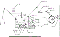
Fig. 1 is the structural representation for the Weaving device of yarn finish.
The specific embodiment
Below in conjunction with accompanying drawing and example the invention process is described further, but enforcement of the present invention and protection domain are not limited to this.
Such as Fig. 1, the Weaving device that is used for yarn finish comprise for the work nest 3 of placing maceration extract (be finishing agent, adopt acid-fast alkali-proof solution), be used for supply maceration extract and monitoring maceration extract temperature fluid infusion groove 4, be used for the frequency conversion system that the control yarn is crossed the servomotor air pressure linkage of liquid time and is used for control yarn winding speed; Work nest 3 lower ends are provided with the first opening that is communicated with described fluid infusion groove 4, above the first opening, be provided with the yarn tension bracket for the yarn process, yarn tension bracket is connected with servomotor air pressure linkage, be provided with for maceration extract in the groove near the side of fluid infusion grooves 4 at work nest 3 and flow into the second opening of fluid infusion groove (when liquid level will flow into the fluid infusion groove from this second opening during to certain altitude, by return duct 4-3 to circulation pump 6-1 to the work nest fluid infusion, form circulation), be provided with the fluid level controller 4-2 for level monitoring in the described fluid infusion groove, the temperature controller 4-1 that is used for the monitoring fluid temperature, the liquid supply device 4-4 that is used for the supply maceration extract; Be provided with circulation pump 6-1 between work nest 3 lower ends the first opening and the fluid infusion groove, be used for fluid infusion groove liquid-circulating to work nest.Liquid supply device 4-4 is positioned at the bead direction of fluid infusion groove.
Such as Fig. 1, yarn tension bracket comprises: be installed in the first yarn blocking rod 3-6 on work nest one side, place the first mistake liquid bar 3-1, second of work nest 3 maceration extracts to cross excessively liquid bar 3-3 of liquid bar 3-2 and the 3rd, be installed in the first tension link 3-4 and the second tension link 3-5 in the work nest, and be installed in the second yarn blocking rod 3-7 on another side of work nest; The position at described the first tension link 3-4 and the second tension link 3-5 place is higher than the first mistake liquid bar 3-1, second and crosses the position that liquid bar 3-2 and the 3rd crosses liquid bar 3-3 place, and the work nest side at described the first yarn blocking rod 3-6 place is over against another side of the work nest at the second yarn blocking rod 3-7 place.Described first crosses liquid bar 3-1, second crosses liquid bar 3-2 and the 3rd and crosses liquid bar 3-3 and be arranged in order in the horizontal direction, and the second position of crossing liquid bar 3-2 place is higher than first and crosses the position that liquid bar 3-1 and the 3rd crosses liquid bar 3-3 place.Be provided with successively the first yarn passing rod 5-1, the second yarn passing rod 5-2, the 3rd yarn passing rod 5-3 and twizzle 5-4 between the second yarn blocking rod 3-7 and the described frequency conversion system.Frequency conversion system comprises variable-frequency motor 5-5 and the row's of shaking machine 5, and variable-frequency motor 5-5 links to each other with the row of shaking machine 5.
Servomotor air pressure linkage comprises the servo motor device 1 and cylinder 3-8 that is installed on the frame 2, and servo motor device 1 is connected with the end of cylinder 3-8, and yarn tension bracket is installed in the other end of cylinder 3-8, and described bracket height is adjustable.
Implementation method:
As shown in Figure 1, yarn is through the first yarn blocking rod 3-6, then liquid bar 3-1, the second mistake liquid bar 3-2 and the 3rd cross liquid bar 3-3 excessively to enter first in the maceration extract, pass through again the first tension link 3-4 and the second tension link 3-5 in the work nest, from the second yarn blocking rod 3-7 out, through the first yarn passing rod 5-1, the second yarn passing rod 5-2, the 3rd yarn passing rod 5-3 and twizzle 5-4, link to each other with the row of shaking machine 5 at last.The structural design of whole equipment is so that arrangement process technique is more stable, and the product reappearance improves.The fluid level controller of level monitoring (liquid level gauge), temperature controller, liquid supply device 4-4 and circulation pump all belong to prior art, no longer describe.
Servo motor device (SYD) 1 is contained on the frame 2 with cylinder 3-8, and bracket height is adjustable, and adjusting the degree of depth of liquid bar in liquid, variable-frequency motor 5-5 links to each other with the row of shaking machine 5, can regulate arbitrarily the speed of a motor vehicle of the row's of shaking machine.The interlocking system that servo motor device 1 and cylinder form and variable-frequency motor etc. all belong to prior art, no longer describe.
Example 1:
When required yarn style is when evenly putting style in order, yarn passes successively all bars and links to each other with the row of shaking machine by above-mentioned, close servomotor air pressure linkage, regulating the variable-frequency motor speed of a motor vehicle is a certain steady state value such as F=35.0 hertz, control liquid bar (first cross liquid bar 3-1, second cross liquid bar 3-2 and the 3rd cross liquid bar 3-3) and placed a certain degree of depth of maceration extract such as H=3.0cm, set the row's of shaking length according to shaking simple lay reeled yarn weight.Start every control system (fluid level controller, temperature controller, liquid supply device and circulation pump) in work nest and the fluid infusion groove, when reaching design temperature, start the row's of shaking machine, namely get and evenly put yarn in order.
Example 2:
When required yarn style is put style in order for being interrupted, yarn passes successively in a manner described all bars and links to each other with the row of shaking machine, start servomotor air pressure linkage, according to the discontinuity treatment length of yarn, setting the disconnection parameter is 0-30.0 second, and the adhesive parameter is 0-30.0 second, and regulating the variable-frequency motor speed of a motor vehicle is a certain steady state value such as F=35.0 hertz, control the liquid bar and placed a certain degree of depth of liquid such as H=3.0cm, set the row's of shaking length according to shaking simple lay reeled yarn weight.Start every control system (fluid level controller, temperature controller, liquid supply device and circulation pump) in work nest and the fluid infusion groove, when reaching design temperature, start the row's of shaking machine, namely get and be interrupted the arrangement yarn.
Example 3:
When required yarn style is gradual change arrangement style, yarn passes successively all bars by above-mentioned implementation method and links to each other with the row of shaking machine, close servomotor air pressure linkage, process the yarn style according to gradual change, regulating the variable-frequency motor speed of a motor vehicle is a certain group of series of values, scope is between 0-100.0, the group number is that the 2-50 group does not wait, the row's of shaking time of the corresponding variable-frequency motor speed of a motor vehicle also is set as corresponding a series of value according to shaking simple lay reeled yarn weight and yarn style, control the liquid bar and placed a certain degree of depth of liquid such as H=3.0cm, set the row's of shaking length according to shaking simple lay reeled yarn weight.Start every control system in the fluid infusion groove, when reaching design temperature, start the row's of shaking machine, namely get gradual change arrangement yarn.
Claims (8)
1. Weaving device that is used for yarn finish, it is characterized in that comprising for the work nest of placing maceration extract, be used for the supply maceration extract the fluid infusion groove, be used for the frequency conversion system that the control yarn is crossed the servomotor air pressure linkage of liquid time and is used for control yarn winding speed; The work nest lower end is provided with the first opening, the first opening links to each other with described fluid infusion groove by circulation pump, above the first opening, be provided with the yarn tension bracket for the yarn process, yarn tension bracket is connected with servomotor air pressure linkage, is provided with the second opening that flows into the fluid infusion groove for maceration extract in the groove near the side of fluid infusion groove at work nest; Described yarn tension bracket comprises: be installed in the first yarn blocking rod (3-6) on work nest one side, place the first mistake liquid bar (3-1), second of work nest maceration extract to cross excessively liquid bar (3-3) of liquid bar (3-2) and the 3rd, be installed in the first tension link (3-4) and the second tension link (3-5) in the work nest, and be installed in the second yarn blocking rod (3-7) on another side of work nest; The position at described the first tension link (3-4) and the second tension link (3-5) place is higher than the first mistake liquid bar (3-1), second and crosses the position that liquid bar (3-2) and the 3rd is crossed liquid bar (3-3) place, and the work nest side at described the first yarn blocking rod (3-6) place is over against another side of the work nest at the second yarn blocking rod (3-7) place.
2. the Weaving device for yarn finish according to claim 1 is characterized in that also being provided with in the described fluid infusion groove for the fluid level controller of level monitoring with for the temperature controller of monitoring fluid temperature.
3. the Weaving device for yarn finish according to claim 2 is characterized in that in the described fluid infusion groove also being provided with along fluid infusion channel opening place the liquid supply device for the supply maceration extract.
4. the Weaving device for yarn finish according to claim 1 is characterized in that being provided with successively between the second yarn blocking rod (3-7) and the described frequency conversion system the first yarn passing rod (5-1), the second yarn passing rod (5-2), the 3rd yarn passing rod (5-3) and twizzle (5-4).
5. the Weaving device for yarn finish according to claim 4 is characterized in that described frequency conversion system comprises variable-frequency motor (5-5) and the row's of shaking machine (5), and variable-frequency motor (5-5) links to each other with the row's of shaking machine (5).
6. the Weaving device for yarn finish according to claim 4, it is characterized in that described first crosses liquid bar (3-1), second and cross liquid bar (3-2) and the 3rd and cross liquid bar (3-3) and be arranged in order in the horizontal direction, and the second position of crossing liquid bar (3-2) place be higher than first cross liquid bar (3-1) and the 3rd the position at liquid bar (3-3) place.
7. each described Weaving device for yarn finish according to claim 1 ~ 6, it is characterized in that described servomotor air pressure linkage comprises the servo motor device (1) and cylinder (3-8) that is installed on the frame (2), servo motor device (1) is connected with an end of cylinder (3-8), yarn tension bracket is installed in the other end of cylinder (3-8), and described bracket height is adjustable.
8. utilize the yarn finish method of the described Weaving device of claim 1, it is characterized in that yarn passes the yarn tension bracket in the described equipment, link to each other with the row of shaking machine again; By opening or close servomotor air pressure linkage, and the disconnection parameter is set, the variable-frequency motor speed of a motor vehicle is a steady state value or is a series of values in the setting range in the adjusting frequency conversion system, control first is crossed liquid bar, second and is crossed liquid bar and the 3rd and cross the degree of depth that the liquid bar places maceration extract one to determine, sets the row's of shaking length according to shaking simple lay reeled yarn weight; Start fluid level controller, temperature controller, liquid supply device and circulation pump in work nest and the fluid infusion groove, when reaching design temperature, start the row's of shaking machine, namely get the arrangement yarn of different-style.
Priority Applications (1)
| Application Number | Priority Date | Filing Date | Title |
|---|---|---|---|
| CN2011100212603A CN102134792B (en) | 2011-01-19 | 2011-01-19 | Textile equipment for yarn finishing and yarn finishing method |
Applications Claiming Priority (1)
| Application Number | Priority Date | Filing Date | Title |
|---|---|---|---|
| CN2011100212603A CN102134792B (en) | 2011-01-19 | 2011-01-19 | Textile equipment for yarn finishing and yarn finishing method |
Publications (2)
| Publication Number | Publication Date |
|---|---|
| CN102134792A CN102134792A (en) | 2011-07-27 |
| CN102134792B true CN102134792B (en) | 2013-02-27 |
Family
ID=44294706
Family Applications (1)
| Application Number | Title | Priority Date | Filing Date |
|---|---|---|---|
| CN2011100212603A Active CN102134792B (en) | 2011-01-19 | 2011-01-19 | Textile equipment for yarn finishing and yarn finishing method |
Country Status (1)
| Country | Link |
|---|---|
| CN (1) | CN102134792B (en) |
Families Citing this family (3)
| Publication number | Priority date | Publication date | Assignee | Title |
|---|---|---|---|---|
| CN105297252B (en) * | 2015-09-22 | 2017-06-20 | 浙江新达经编有限公司 | A kind of fiber blended high elastic fabric and preparation method thereof |
| CN107287790B (en) * | 2017-07-14 | 2024-06-07 | 浙江宇邦滤材科技有限公司 | Impregnating equipment for processing filter bag |
| CN108754945A (en) * | 2018-05-30 | 2018-11-06 | 俞祖林 | A kind of padding machine for textile |
Family Cites Families (9)
| Publication number | Priority date | Publication date | Assignee | Title |
|---|---|---|---|---|
| JPS63126964A (en) * | 1986-11-12 | 1988-05-30 | 合資会社 宮内商店 | Feather removing apparatus in sizing |
| US4793035A (en) * | 1987-09-28 | 1988-12-27 | E. I. Du Pont De Nemours And Company | Dynamic control of textile warp size add-on on a running slasher |
| JPH02251663A (en) * | 1989-03-24 | 1990-10-09 | Tsudakoma Corp | Sizing box apparatus of sizing machine |
| JPH0397951A (en) * | 1989-09-11 | 1991-04-23 | Katsuzawa Denshi Gijutsu Kk | Size pickup control method in warp sizing machine |
| JPH0450357A (en) * | 1990-06-15 | 1992-02-19 | Kawamoto Seiki Kk | Method and device for measuring sizing degree in warp-sizing machine |
| JPH05179563A (en) * | 1991-02-25 | 1993-07-20 | Katsuzawa Denshi Gijutsu Kk | Method for controlling operation of warp sizing machine and apparatus therefor |
| CN1277012C (en) * | 2002-12-30 | 2006-09-27 | 津田驹工业株式会社 | Discharging method for air bubbles and float matter of warp sizing device |
| JP2005060870A (en) * | 2003-08-11 | 2005-03-10 | Tsudakoma Corp | Method for storing and setting operating conditions of warp gluing machine |
| CN201952633U (en) * | 2011-01-19 | 2011-08-31 | 广州纺织服装研究院 | Textile equipment for yarn finish |
-
2011
- 2011-01-19 CN CN2011100212603A patent/CN102134792B/en active Active
Also Published As
| Publication number | Publication date |
|---|---|
| CN102134792A (en) | 2011-07-27 |
Similar Documents
| Publication | Publication Date | Title |
|---|---|---|
| CN102134792B (en) | Textile equipment for yarn finishing and yarn finishing method | |
| CN108466471B (en) | Manufacturing process of multifunctional composite fabric | |
| CN104594079B (en) | A kind of viscose rayon cheese low bath ratio dyeing method | |
| CN108360183A (en) | It is a kind of that there is textile cloth of the drying apart from adjustable function dyeing drying unit | |
| CN102926226B (en) | Printing process for elastic fiber fabric | |
| CN204875153U (en) | Cloth cage dyeing machine is deposited to spiral | |
| CN102011280A (en) | Knitted jean production process and equipment | |
| CN201952633U (en) | Textile equipment for yarn finish | |
| CN205295694U (en) | Frequency conversion dye jigger | |
| CN203475024U (en) | Multifunctional high-speed air coated yarn machine | |
| CN202107813U (en) | Production system for superfine short fibers | |
| CN105129507A (en) | Improved doubling machine | |
| CN201330319Y (en) | Flat wire infection pad dyeing machine | |
| CN208577856U (en) | Yarn flocking gluing machine | |
| CN206015294U (en) | A kind of new type high temperature printing and dyeing cylinder | |
| CN201842968U (en) | Lamellar dyeing multi-start rolling machine | |
| CN205954226U (en) | Weaving of adjustable length is with going out spool | |
| CN205241977U (en) | Rapier loom weft oiling device | |
| CN204385440U (en) | The automatic adjustable flood nozzle of gas-liquid dyeing machine | |
| CN204959233U (en) | Tricot machine with temperature control system | |
| CN109576815A (en) | A kind of polyester filament production method with along fibre length dyeing gradual change performance | |
| CN204753043U (en) | Automatic yarn structure that supplies of permanent tension for warp knitting machine | |
| CN205529287U (en) | Walk traditional thread binding putting | |
| CN205295695U (en) | Permanent tension dye jigger of frequency conversion | |
| CN110565180A (en) | production process of polyester super-dull flat yarn |
Legal Events
| Date | Code | Title | Description |
|---|---|---|---|
| C06 | Publication | ||
| PB01 | Publication | ||
| C10 | Entry into substantive examination | ||
| SE01 | Entry into force of request for substantive examination | ||
| C14 | Grant of patent or utility model | ||
| GR01 | Patent grant | ||
| CP01 | Change in the name or title of a patent holder |
Address after: No.16, Keke Road, Science City, Luogang District, Guangzhou City, Guangdong Province, 510663 Patentee after: Guangdong GuangFang Testing Technology Co.,Ltd. Address before: No.16, Keke Road, Science City, Luogang District, Guangzhou City, Guangdong Province, 510663 Patentee before: GUANGZHOU TEXTILE INDUSTRY Research Institute |
|
| CP01 | Change in the name or title of a patent holder |