CN102403160B - Quick three working position isolation switch - Google Patents
Quick three working position isolation switch Download PDFInfo
- Publication number
- CN102403160B CN102403160B CN201110385764.3A CN201110385764A CN102403160B CN 102403160 B CN102403160 B CN 102403160B CN 201110385764 A CN201110385764 A CN 201110385764A CN 102403160 B CN102403160 B CN 102403160B
- Authority
- CN
- China
- Prior art keywords
- connecting rod
- movable contact
- isolation switch
- rotating shaft
- moving contact
- Prior art date
- Legal status (The legal status is an assumption and is not a legal conclusion. Google has not performed a legal analysis and makes no representation as to the accuracy of the status listed.)
- Active
Links
- 238000002955 isolation Methods 0.000 abstract 3
- 230000005540 biological transmission Effects 0.000 abstract 2
Images

Landscapes
- Driving Mechanisms And Operating Circuits Of Arc-Extinguishing High-Tension Switches (AREA)
Abstract
The invention relates to a quick three working position isolation switch, which comprises a movable contact, a fixed contact and an insulated rotary shaft; the insulated rotary shaft drives the movable contact to move by a transmission mechanism under the control of an operating mechanism so as to be connected or disconnected with the fixed contact. The isolation switch also comprises a movable contact seat; the front end of the movable contact seat is provided with a first cylindrical hole for receiving the movable contact and a second cylindrical hole for mounting the insulated rotary shaft; the two cylindrical holes are vertical to each other, and cavities for other parts to move are arranged in parallel between the two cylindrical holes; the transmission mechanism comprises a connecting rod and a connecting rod sleeve, and one end of the connecting rod sleeve is tightly connected with the insulated rotary shaft by cooperation of key and slot, while the other end is provided with a cavity for receiving the connecting rod and is slidingly connected with the connecting rod; and one end of the connecting rod extends in a cavity of the connecting rod sleeve and is slidingly connected with the connecting rod sleeve, while the other end is rotationally connected with the movable contact through a pin shaft. The quick three working position isolation switch has simple structure and can quickly transmit energy from the operating mechanism to quickly finish translation of the movable contact.
Description
Technical field
The invention belongs to field of switches, particularly, is a kind of Quick three working position isolation switch.
Background technology
The tri-station isolating switch of current gas-insulated metal enclosed switchgear (being called for short GIS) use, its Main Function is isolation circuit, sets up isolated insulation fracture.About this kind of switch, the applicant once applied for < < by name Chinese patent with the isolating switch > > of fast minute function, application number is 200910097455, and the application is the further improvement on this application basis.
In first to file, mentioned with operating mechanism and driven insulation rotating shaft to rotate, but and unexposed concrete operating mechanism and drive mechanism, in actual production, generally adopt rack-and-pinion transmission, with rotating shaft, directly drive the motion of moving contact.Its shortcoming is to join Slow-disconnecting and slow-connecting mechanism, and divide-shut brake speed is lower, and body interior is not established arc-control device, as common isolating switch, uses, and does not have great problem.But at the bus isolating switch such as in double bus scheme and bypass connection, also must be used for conversion line, this inevitable requirement opening-closing bus switching current (being commonly called as circulation).During opening-closing bus switching current, the arcing time is longer, can make contact burning, and can produce metal splash during arcing, causes insulator surface pollution severity, directly affects the interior insulation property of GIS.Isolating switch also can produce fast transient overvoltage when cutting little capacitance current in addition, to equipment, may damage.And improve minute sum velocity, be the best of solving these two problems by way of one of.
In addition, adopt the tri-station isolating switch of rack-and-pinion drive mechanism, one of existing employing is integrally-built shaft-driven, and due to the effect of air pressure, rack-and-pinion has the phenomenon of de-tooth to occur.Also have and adopt segmentation shaft-driven, structure is more complicated, and due to the accumulation in the gap of each section of shaft connection place, divide-shut brake synchronism is also poor.
Summary of the invention
The present invention will solve is effectively opening-closing bus switching current and the existing too complicated technical problem of isolating switch structure that can opening-closing bus switching current provides a kind of Quick three working position isolation switch simple in structure of common tri-station isolating switch.
The present invention adopts following technical scheme: Quick three working position isolation switch, comprise moving contact, fixed contact, insulation rotating shaft, insulation rotating shaft is under the control of operating mechanism, by transmission mechanism, drive moving contact to move, close with fixed contact or separated, it also comprises a movable contact block, and movable contact block front end is useful on and holds the first cylindrical hole of moving contact and for the second cylindrical hole of installing insulating rotating shaft, two cylindrical holes are orthogonal, between two cylindrical holes and be provided with the cavity for miscellaneous part motion; Described transmission mechanism comprises connecting rod and connecting rod cover, and connecting rod cover one end coordinates tightening to be connected with the rotating shaft of insulating by keyway, and the other end has and holds the cavity of connecting rod and be connected with rod slide; Connecting rod one end is stretched in the cavity of connecting rod cover and is slidably connected with it, and the other end and moving contact are rotationally connected by bearing pin.
As further technical scheme, described fixed contact comprises a cup-shaped body, thereby the some grooves of being axially arranged with of its inwall form fingertips, inwall be circumferentially with the inside annular projection of two circles, be one in front and one in back arranged in parallel, and be sintered to one with body; Wherein above a circle is copper-tungsten, after a circle be chromiumcopper.
The present invention is when work, and operating mechanism is controlled insulation rotating shaft and rotated, and drivening rod cover rotates, thereby makes connecting rod swing, and then makes moving contact do translational motion in the first cylindrical hole, realizes therefrom the control to isolating switch.When moving contact arrives behind fixed contact position, first it contact with first lap copper-tungsten, continue to contact with the second circle chromiumcopper after motion, before a circle copper-tungsten as arc fingertip, a circle chromiumcopper conductivity next is high, the available fingertip of deciding, body itself also can adopt chromiumcopper simultaneously.When isolating switch closes a floodgate, moving contact approaches to fixed contact, gap breakdown electric discharge (while referring to opening-closing bus switching current), due to the arc fingertip of fixed contact outside, electric arc burns on arc fingertip, along with moving contact moves forward, moving contact contacts with arc fingertip, electric arc disappears, and finally contacts with the main fingertip of fixed contact, completes combined floodgate.During separating brake, moving contact is first separated with the main fingertip of fixed contact, because arc fingertip is also not separated, therefore main fingertip can not produce electric arc, along with the continuation campaign of moving contact, just produce electric arc separated with arc fingertip, dynamic/static contact reaches after certain distance, and arc extinction finally reaches gate-dividing state.
The present invention can join three station Slow-disconnecting and slow-connecting mechanisms, as common tri-station isolating switch, uses; Also can join three station spring mechanisms, thereby improve the point-to-point speed of moving contact, make it have and divide soon soon close function.
Traditional rack and pinion drive mechanism, the link of its transmission is more, if matched with the operating mechanism of the abrupt release energy such as spring mechanism, the speed of its transferring energy does not catch up with exergonic speed, thereby has affected the translational speed of moving contact; And transmission mechanism of the present invention is simple in structure, initial connecting rod cover pendulum angle is quite little, and the pivot joint relation by connecting rod and moving contact is converted into line by angular movement and moves, the translation stroke that can obtain growing with less angle of oscillation.Therefore, can promptly transmit the energy that operating mechanism transmits, complete fast the translation of moving contact.
On the other hand, the present invention is integrated into main fingertip and arc fingertip on same fixed contact, can complete the function of two kinds of contacts, and structure is very simple simultaneously.
Fig. 1 is structural representation of the present invention.
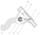
Fig. 2 is the schematic diagram of moving contact and transmission mechanism in the present invention.
Fig. 3 is the schematic diagram of fixed contact in the present invention.
Referring to accompanying drawing.The present embodiment comprises moving contact 1 and fixed contact 2, and fixed contact 2 comprises a cup-shaped body, is evenly equipped with some axial grooves 22 on wall of cup, and these grooves extend to outer wall from inwall, become penetrating groove; Inwall front portion is furnished with the inwardly protruded ring 23 of two circles and 24, encircles 23 and 24 parallel to each otherly, wherein encircles 23 tops that are positioned at cup, encircles 24 after ring 23; Ring 23 itself is a part for body, encircles 24 and be sintered to one with body when blank.Ring 23 material is copper-tungsten, encircle 24 and the material of cup body be chromiumcopper.
The present embodiment is provided with movable contact block 4, and its front end is useful on and holds the first cylindrical hole 41 of moving contact and orthogonal for the second cylindrical hole 42, two cylindrical holes 42 and 42 of installing insulating rotating shaft 3, between two cylindrical holes and be provided with the cavity for miscellaneous part motion; Also comprise connecting rod cover 5 and connecting rod 6, connecting rod overlaps 5 one end and by keyway, coordinates tightening to be connected with insulation rotating shaft 3, and the other end and connecting rod 6 are slidably connected; Connecting rod 6 one end are stretched in the cavity of connecting rod cover 5 and are slidably connected with it, and the other end and moving contact 1 are rotationally connected by bearing pin 7.
During the present embodiment work, insulation rotating shaft 3 is rotated, and drivening rod cover 5 rotates, connecting rod overlaps 5 drivening rods 6 and swings, connecting rod 6 drives moving contacts 1 to do translational motion the first cylindrical hole 41 is interior, with the ring 23,24 of fixed contact in conjunction with or separated, thereby complete combined floodgate, the separating brake of switch.
Claims (2)
1. Quick three working position isolation switch, comprise moving contact, fixed contact, insulation rotating shaft, insulation rotating shaft is under the control of operating mechanism, by transmission mechanism, drive moving contact to move, close with fixed contact or separated, it is characterized in that: it also comprises a movable contact block, movable contact block front end is useful on and holds the first cylindrical hole of moving contact and for the second cylindrical hole of installing insulating rotating shaft, two cylindrical holes are orthogonal, between two cylindrical holes and be provided with the cavity for miscellaneous part motion; Described transmission mechanism comprises connecting rod and connecting rod cover, and connecting rod cover one end coordinates tightening to be connected with the rotating shaft of insulating by keyway, and the other end has and holds the cavity of connecting rod and be connected with rod slide; Connecting rod one end is stretched in the cavity of connecting rod cover and is slidably connected with it, and the other end and moving contact are rotationally connected by bearing pin.
2. Quick three working position isolation switch as claimed in claim 1, it is characterized in that: described fixed contact comprises a cup-shaped body, thereby the some grooves of being axially arranged with of its inwall form fingertips, inwall be circumferentially with the inside annular projection of two circles, be one in front and one in back arranged in parallel; Wherein above a circle is copper-tungsten, is a part for body, after a circle be chromiumcopper, be sintered to one with body.
Priority Applications (1)
| Application Number | Priority Date | Filing Date | Title |
|---|---|---|---|
| CN201110385764.3A CN102403160B (en) | 2011-11-29 | 2011-11-29 | Quick three working position isolation switch |
Applications Claiming Priority (1)
| Application Number | Priority Date | Filing Date | Title |
|---|---|---|---|
| CN201110385764.3A CN102403160B (en) | 2011-11-29 | 2011-11-29 | Quick three working position isolation switch |
Publications (2)
| Publication Number | Publication Date |
|---|---|
| CN102403160A CN102403160A (en) | 2012-04-04 |
| CN102403160B true CN102403160B (en) | 2014-03-12 |
Family
ID=45885252
Family Applications (1)
| Application Number | Title | Priority Date | Filing Date |
|---|---|---|---|
| CN201110385764.3A Active CN102403160B (en) | 2011-11-29 | 2011-11-29 | Quick three working position isolation switch |
Country Status (1)
| Country | Link |
|---|---|
| CN (1) | CN102403160B (en) |
Families Citing this family (1)
| Publication number | Priority date | Publication date | Assignee | Title |
|---|---|---|---|---|
| CN110060904B (en) * | 2019-06-06 | 2024-04-19 | 现代重工(中国)电气有限公司 | Novel isolating switch contact structure |
Citations (6)
| Publication number | Priority date | Publication date | Assignee | Title |
|---|---|---|---|---|
| EP0599742A1 (en) * | 1992-11-26 | 1994-06-01 | Schneider Electric Sa | Off-and-on mechanism for an electric medium-high or high voltage circuit breaker |
| CN101527220A (en) * | 2009-04-03 | 2009-09-09 | 浙江开关厂有限公司 | Isolating switch with fast separating function |
| CN201360109Y (en) * | 2009-02-20 | 2009-12-09 | 国电博纳(北京)电力设备有限公司 | 126KV composite type combined electrical appliance |
| CN201536079U (en) * | 2009-08-27 | 2010-07-28 | 广州白云电器设备股份有限公司 | Three position switch of high pressure gas-insulated switchgear device |
| CN201622941U (en) * | 2010-01-12 | 2010-11-03 | 正泰电气股份有限公司 | A self-acting contact |
| CN202384244U (en) * | 2011-11-29 | 2012-08-15 | 浙江开关厂有限公司 | Quick three-position isolation switch |
-
2011
- 2011-11-29 CN CN201110385764.3A patent/CN102403160B/en active Active
Patent Citations (6)
| Publication number | Priority date | Publication date | Assignee | Title |
|---|---|---|---|---|
| EP0599742A1 (en) * | 1992-11-26 | 1994-06-01 | Schneider Electric Sa | Off-and-on mechanism for an electric medium-high or high voltage circuit breaker |
| CN201360109Y (en) * | 2009-02-20 | 2009-12-09 | 国电博纳(北京)电力设备有限公司 | 126KV composite type combined electrical appliance |
| CN101527220A (en) * | 2009-04-03 | 2009-09-09 | 浙江开关厂有限公司 | Isolating switch with fast separating function |
| CN201536079U (en) * | 2009-08-27 | 2010-07-28 | 广州白云电器设备股份有限公司 | Three position switch of high pressure gas-insulated switchgear device |
| CN201622941U (en) * | 2010-01-12 | 2010-11-03 | 正泰电气股份有限公司 | A self-acting contact |
| CN202384244U (en) * | 2011-11-29 | 2012-08-15 | 浙江开关厂有限公司 | Quick three-position isolation switch |
Non-Patent Citations (1)
| Title |
|---|
| 张洁等.铜钨(70)自力型触头的研制.《华通技术》.1995,(第2期), * |
Also Published As
| Publication number | Publication date |
|---|---|
| CN102403160A (en) | 2012-04-04 |
Similar Documents
| Publication | Publication Date | Title |
|---|---|---|
| CN102024606B (en) | Three-station isolation ground switch | |
| CN102568910B (en) | 1100kV extra-high voltage series complement bypass switch | |
| JP2015023685A (en) | Switchgear | |
| CN203070998U (en) | Ball screw transmitted three-position isolation grounding switch | |
| CN201360109Y (en) | 126KV composite type combined electrical appliance | |
| CN103903901B (en) | The contact mechanism of three station high-voltage switch gears | |
| CN102403160B (en) | Quick three working position isolation switch | |
| CN204303716U (en) | A kind of two moving contact circuit breaker | |
| CN103715007B (en) | Tri-station isolating switch station locking mechanism | |
| CN103177901A (en) | Three-position switch operating mechanism | |
| CN202384244U (en) | Quick three-position isolation switch | |
| CN203871258U (en) | Contact mechanism of three-station high-voltage switch | |
| CN204303671U (en) | The operating mechanism of a kind of pair of moving contact breaker | |
| WO2016034088A1 (en) | Composite combined electric appliance | |
| CN106611675A (en) | Compact three-position isolated earthing switch | |
| CN203690195U (en) | Station locking mechanism of three-station isolating switch | |
| CN219759439U (en) | A kind of double-break isolation grounding switch | |
| CN103489704B (en) | A kind of vacuum circuit breaker operating device | |
| CN219575491U (en) | Isolation switch | |
| CN104766752B (en) | Compact disconnecting switch | |
| CN207896023U (en) | A kind of linear type bus isolating switch | |
| CN203134658U (en) | Three-position switch operating mechanism | |
| CN104681346B (en) | The linkage for the actuating disconnecting switch plug-in strip for keeping SBS synchronous with the disconnecting switch of RMU | |
| CN105761966A (en) | Stepping three-station switch | |
| CN109004535A (en) | A kind of New Type Isolating Switch |
Legal Events
| Date | Code | Title | Description |
|---|---|---|---|
| C06 | Publication | ||
| PB01 | Publication | ||
| C10 | Entry into substantive examination | ||
| SE01 | Entry into force of request for substantive examination | ||
| GR01 | Patent grant | ||
| GR01 | Patent grant |