CN102419002A - Equipment combining heat pump water heater and drinking fountain - Google Patents
Equipment combining heat pump water heater and drinking fountain Download PDFInfo
- Publication number
- CN102419002A CN102419002A CN2011103478257A CN201110347825A CN102419002A CN 102419002 A CN102419002 A CN 102419002A CN 2011103478257 A CN2011103478257 A CN 2011103478257A CN 201110347825 A CN201110347825 A CN 201110347825A CN 102419002 A CN102419002 A CN 102419002A
- Authority
- CN
- China
- Prior art keywords
- water
- drinking water
- heat exchanger
- water tank
- exchanger
- Prior art date
- Legal status (The legal status is an assumption and is not a legal conclusion. Google has not performed a legal analysis and makes no representation as to the accuracy of the status listed.)
- Granted
Links
Images

Classifications
-
- Y—GENERAL TAGGING OF NEW TECHNOLOGICAL DEVELOPMENTS; GENERAL TAGGING OF CROSS-SECTIONAL TECHNOLOGIES SPANNING OVER SEVERAL SECTIONS OF THE IPC; TECHNICAL SUBJECTS COVERED BY FORMER USPC CROSS-REFERENCE ART COLLECTIONS [XRACs] AND DIGESTS
- Y02—TECHNOLOGIES OR APPLICATIONS FOR MITIGATION OR ADAPTATION AGAINST CLIMATE CHANGE
- Y02B—CLIMATE CHANGE MITIGATION TECHNOLOGIES RELATED TO BUILDINGS, e.g. HOUSING, HOUSE APPLIANCES OR RELATED END-USER APPLICATIONS
- Y02B30/00—Energy efficient heating, ventilation or air conditioning [HVAC]
- Y02B30/12—Hot water central heating systems using heat pumps
Landscapes
- Devices That Are Associated With Refrigeration Equipment (AREA)
- Other Air-Conditioning Systems (AREA)
Abstract
一种热泵热水器与饮水机组合设备,包括通过管道相连的压缩机、四通阀、室外换热器及其承压水箱,承压水箱的内腔中设置有水箱热交换器,水箱热交换器的输入端设置有带热饮水交换器的热饮水部件,水箱热交换器的输出端设置有带冷饮水交换器的冷饮水部件;水箱热交换器与热饮水交换器及冷饮水交换器共同构成一冷媒循环回路。本发明在水箱热交换器的输入端和输出端分别增设热饮水交换器及冷饮水交换器,在制取生活热水同时,利用高温高压的冷媒换热加热饮水,及利用低温低压的冷媒制取冷饮水,能提供多种水温的饮用水,以实现一机多能,并且节省室内电器占用的空间,提高换热效率;其具有结构简单合理、能耗低、使用寿命长和成本低廉的特点。
A heat pump water heater and water dispenser combination equipment, including a compressor connected through pipelines, a four-way valve, an outdoor heat exchanger and a pressurized water tank, a water tank heat exchanger is arranged in the inner cavity of the pressurized water tank, and the water tank heat exchanger The input end of the water tank is provided with a hot drinking water part with a hot drinking water exchanger, and the output end of the water tank heat exchanger is provided with a cold drinking water part with a cold drinking water exchanger; the water tank heat exchanger is composed of a hot drinking water exchanger and a cold drinking water exchanger A refrigerant circulation loop. The present invention adds a hot drinking water exchanger and a cold drinking water exchanger respectively at the input end and the output end of the heat exchanger of the water tank. While producing domestic hot water, the high temperature and high pressure refrigerant is used for heat exchange to heat drinking water, and the low temperature and low pressure refrigerant is used to prepare the drinking water. It can take cold drinking water and provide drinking water at various temperatures to realize multiple functions of one machine, save the space occupied by indoor electrical appliances, and improve heat exchange efficiency; it has the advantages of simple and reasonable structure, low energy consumption, long service life and low cost. features.
Description
技术领域 technical field
本发明涉及一种热泵热水器与饮水机组合设备。The invention relates to a combination device of a heat pump water heater and a water dispenser.
背景技术 Background technique
目前,家庭用饮水机和热泵热水器是两个单独的电器,中国专利文献号CN102022828A于2011年4月20日公开了一种设置有饮水机的热泵热水器,其包括压缩机,节流机构,风机,蒸发器,控制系统,保温水桶以及设置在保温水桶内的冷凝器,其特征在于:热泵热水器体内还设置有饮用水管路,其包括热水管和冷水管,所述的热水管穿过保温水桶,所述的冷水管的部分管路紧邻蒸发器。据称,其利用热泵热水器对饮用水进行加热/制冷,不但省去单独的饮水机,节省了用电量。但是该结构存在以下一些不足之处:1、热泵加热保温水桶内水温一般55度以下,此结构把饮用水热水管置于保温水桶内,通过二次换热加热饮用水,造成温度偏低和换热效率低;2、必须配备电加热器进行电加热,占用电量;3、冷水管放置在蒸发器附近,靠辐射来制冷,制冷效果非常有限,不能保证夏天冷饮水效果。因此,有必要作进一步改进和完善。At present, household water dispensers and heat pump water heaters are two separate electrical appliances. Chinese Patent Document No. CN102022828A disclosed a heat pump water heater equipped with a water dispenser on April 20, 2011, which includes a compressor, a throttling mechanism, and a fan. , an evaporator, a control system, an insulated water bucket and a condenser arranged in the insulated water bucket, characterized in that: the heat pump water heater body is also provided with a drinking water pipeline, which includes a hot water pipe and a cold water pipe, and the hot water pipe wears Through the thermal insulation bucket, part of the pipeline of the cold water pipe is close to the evaporator. It is said that it uses a heat pump water heater to heat/cool drinking water, which not only saves a separate water dispenser, but also saves electricity consumption. However, this structure has the following disadvantages: 1. The water temperature in the thermal insulation bucket heated by the heat pump is generally below 55 degrees. and low heat exchange efficiency; 2. Electric heaters must be equipped for electric heating, which consumes electricity; 3. The cold water pipe is placed near the evaporator and is cooled by radiation. The cooling effect is very limited, and the effect of cold drinking water in summer cannot be guaranteed. Therefore, it is necessary to further improve and perfect.
发明内容 Contents of the invention
本发明的目的旨在提供一种结构简单合理、节能环保、占用空间小、和提高换热效率的热泵热水器与饮水机组合设备,以克服现有技术中的不足之处。The object of the present invention is to provide a combined heat pump water heater and water dispenser with simple and reasonable structure, energy saving and environmental protection, small space occupation, and improved heat exchange efficiency, so as to overcome the shortcomings in the prior art.
按此目的设计的一种热泵热水器与饮水机组合设备,包括通过管道相连的压缩机、四通阀、室外换热器及其承压水箱,承压水箱上设置有水箱热交换器,其结构特征是所述水箱热交换器的输入端设置有带热饮水交换器的热饮水部件,水箱热交换器的输出端设置有带冷饮水交换器的冷饮水部件;水箱热交换器与热饮水交换器及冷饮水交换器共同构成一冷媒循环回路。A combination of heat pump water heater and water dispenser designed for this purpose, including a compressor connected through pipelines, a four-way valve, an outdoor heat exchanger and a pressurized water tank. A water tank heat exchanger is arranged on the pressurized water tank. Its structure The feature is that the input end of the water tank heat exchanger is provided with a hot drinking water component with a hot drinking water exchanger, and the output end of the water tank heat exchanger is provided with a cold drinking water component with a cold drinking water exchanger; the water tank heat exchanger exchanges hot drinking water The device and the cold drinking water exchanger together form a refrigerant circulation loop.
所述冷饮水交换器设置于冷饮水部件的内腔中,冷饮水交换器的一端上设置有电子膨胀阀,电子膨胀阀分别与水箱热交换器和冷饮水交换器为串联连接;冷饮水交换器的另一端与室外换热器相连,室外换热器与冷饮水交换器之间设置有第二单向阀。The cold drinking water exchanger is arranged in the inner cavity of the cold drinking water component, and one end of the cold drinking water exchanger is provided with an electronic expansion valve, and the electronic expansion valve is respectively connected in series with the water tank heat exchanger and the cold drinking water exchanger; the cold drinking water exchange The other end of the device is connected with the outdoor heat exchanger, and a second one-way valve is arranged between the outdoor heat exchanger and the cold drinking water exchanger.
所述热饮水交换器设置于热饮水部件的内腔中,热饮水交换器与水箱热交换器相连处设置有第一单向阀,热饮水交换器上还设有与之并联连接的第四单向阀,第四单向阀的一端与水箱热交换器相连,第四单向阀的另一端和热饮水交换器与四通阀的a接口相连。The hot drinking water exchanger is arranged in the inner cavity of the hot drinking water component, a first one-way valve is arranged at the connection between the hot drinking water exchanger and the water tank heat exchanger, and a fourth check valve connected in parallel with it is arranged on the hot drinking water exchanger. As for the one-way valve, one end of the fourth one-way valve is connected with the heat exchanger of the water tank, and the other end of the fourth one-way valve is connected with the interface a of the four-way valve with the hot drinking water exchanger.
所述四通阀的c接口与室外换热器的一端相连接,室外换热器的另一端与电子膨胀阀之间设置有第三单向阀;压缩机的两端分别与四通阀的d接口及b接口相连。The c interface of the four-way valve is connected to one end of the outdoor heat exchanger, and a third check valve is arranged between the other end of the outdoor heat exchanger and the electronic expansion valve; the two ends of the compressor are connected to the four-way valve respectively. The d interface is connected to the b interface.
本发明在通过水箱热交换器的输入端和输出端分别增设热饮水交换器及冷饮水交换器,在制取生活热水同时,利用高温高压的冷媒换热加热饮水,及利用低温低压的冷媒制取冷饮水,能提供多种水温的饮用水,以实现一机多能,并且节省室内电器占用的空间;同时低温低压的冷媒可以起到过冷保护的作用,提高换热效率;其具有结构简单合理、能耗低、使用寿命长、成本低廉和便于加工生产的特点。The present invention adds a hot drinking water exchanger and a cold drinking water exchanger respectively at the input end and the output end of the water tank heat exchanger, while producing domestic hot water, utilizes high-temperature and high-pressure refrigerant heat exchange to heat drinking water, and utilizes low-temperature and low-pressure refrigerant To produce cold drinking water, it can provide drinking water with various temperatures to realize multiple functions of one machine and save the space occupied by indoor electrical appliances; at the same time, the low-temperature and low-pressure refrigerant can play the role of over-cooling protection and improve heat exchange efficiency; it has It has the characteristics of simple and reasonable structure, low energy consumption, long service life, low cost and easy processing and production.
附图说明 Description of drawings
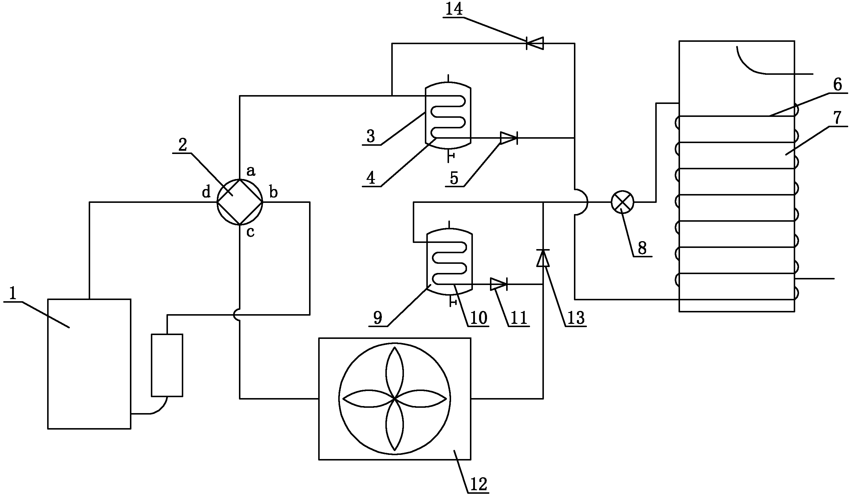
图1为本发明的一实施例的工作原理示意图。FIG. 1 is a schematic diagram of the working principle of an embodiment of the present invention.
图中:1为压缩机,2为四通阀,3为热饮水部件,4为热饮水交换器,5为第一单向阀,6为水箱热交换器,7为承压水箱,8为电子膨胀阀,9为冷饮水部件,10为冷饮水交换器,11为第二单向阀,12为室外换热器,13为第三单向阀,14为第四单向阀。In the figure: 1 is the compressor, 2 is the four-way valve, 3 is the hot drinking water component, 4 is the hot drinking water exchanger, 5 is the first one-way valve, 6 is the water tank heat exchanger, 7 is the pressurized water tank, 8 is Electronic expansion valve, 9 is a cold drinking water component, 10 is a cold drinking water exchanger, 11 is a second one-way valve, 12 is an outdoor heat exchanger, 13 is a third one-way valve, and 14 is a fourth one-way valve.
具体实施方式 Detailed ways
下面结合附图及实施例对本发明作进一步描述。The present invention will be further described below in conjunction with the accompanying drawings and embodiments.
参见图1,本热泵热水器与饮水机组合设备,包括通过管道相连的压缩机1、四通阀2、室外换热器12及其承压水箱7。四通阀2的c接口与室外换热器12的一端相连接,压缩机1的两端分别与四通阀2的d接口及b接口相连,承压水箱7上设置有水箱热交换器6。水箱热交换器6的输入端设置有带热饮水交换器4的热饮水部件3,水箱热交换器6的输出端设置有带冷饮水交换器10的冷饮水部件9,水箱热交换器6与热饮水交换器4及冷饮水交换器10共同构成一冷媒循环回路,其目的在于:在制取生活热水同时,利用高温高压的冷媒换热加热饮水,及利用低温低压冷媒制取冷饮水,以实现一机多能,并减小产品的体积。Referring to FIG. 1 , the heat pump water heater and water dispenser combination equipment includes a compressor 1 , a four-way valve 2 , an outdoor heat exchanger 12 and a pressurized water tank 7 connected through pipelines. The c interface of the four-way valve 2 is connected to one end of the outdoor heat exchanger 12, the two ends of the compressor 1 are respectively connected to the d interface and the b interface of the four-way valve 2, and the pressurized water tank 7 is provided with a water
热饮水交换器4设置于热饮水部件3的内腔中,热饮水交换器4与水箱热交换器6相连处设置有第一单向阀5,热饮水交换器4上还设有与之并联连接的第四单向阀14。第四单向阀14的一端与水箱热交换器6相连,第四单向阀的另一端和热饮水交换器4与四通阀2的a接口相连。运行时,冷媒经压缩机1压缩后成高压高温气体流经向四通阀2,该四通阀2为断电状态,冷媒从四通阀2流向热饮水交换器4,加热热饮水部件3内部的饮用水。然后冷媒通过第一单向阀5进入水箱热交换器6的输入端,且与水箱热交换器6进行热交换,加热承压水箱7中的水。冷媒从水箱热交换器6的输出端经电子膨胀阀8后变为低压冷媒,流向冷饮水交换器10冷却冷饮水装置内的饮用水后,通过第二单向阀11流向室外换热器12,吸收空气中的热量蒸发后,流经四通阀2被吸回流至压缩机1完成一个工作循环。The hot drinking water exchanger 4 is arranged in the inner cavity of the hot drinking water component 3, and a first one-way valve 5 is arranged at the connection between the hot drinking water exchanger 4 and the water
冷饮水交换器10设置于冷饮水部件9的内腔中,冷饮水交换器10的一端上设置有电子膨胀阀8,电子膨胀阀8分别与水箱热交换器6和冷饮水交换器10为串联连接。冷饮水交换器10的另一端与室外换热器12相连,室外换热器12与冷饮水交换器10之间设置有第二单向阀11,室外换热器12的另一端与电子膨胀阀8之间设置有第三单向阀13。融霜时,冷媒经压缩机1压缩后成高压高温气体流经四通阀2,四通阀2为通电状态,冷媒从四通阀2流向室外换热器12进行融霜,冷媒再流经第三单向阀13和电子膨胀阀8流向水箱热交换器6,冷媒从水箱热交换器6出来经单向阀回到四通阀2,被吸回至压缩机1,如此反复循环。The cold drinking water exchanger 10 is arranged in the inner cavity of the cold drinking water component 9, and one end of the cold drinking water exchanger 10 is provided with an electronic expansion valve 8, and the electronic expansion valve 8 is connected in series with the water
Claims (4)
Priority Applications (1)
| Application Number | Priority Date | Filing Date | Title |
|---|---|---|---|
| CN201110347825.7A CN102419002B (en) | 2011-11-04 | 2011-11-04 | Teat pump boiler and water dispenser unit equipment |
Applications Claiming Priority (1)
| Application Number | Priority Date | Filing Date | Title |
|---|---|---|---|
| CN201110347825.7A CN102419002B (en) | 2011-11-04 | 2011-11-04 | Teat pump boiler and water dispenser unit equipment |
Publications (2)
| Publication Number | Publication Date |
|---|---|
| CN102419002A true CN102419002A (en) | 2012-04-18 |
| CN102419002B CN102419002B (en) | 2016-08-24 |
Family
ID=45943537
Family Applications (1)
| Application Number | Title | Priority Date | Filing Date |
|---|---|---|---|
| CN201110347825.7A Expired - Fee Related CN102419002B (en) | 2011-11-04 | 2011-11-04 | Teat pump boiler and water dispenser unit equipment |
Country Status (1)
| Country | Link |
|---|---|
| CN (1) | CN102419002B (en) |
Cited By (3)
| Publication number | Priority date | Publication date | Assignee | Title |
|---|---|---|---|---|
| CN105091149A (en) * | 2014-05-04 | 2015-11-25 | 中山市雅西环保科技有限公司 | Air conditioner with water dispenser |
| CN107192130A (en) * | 2017-06-12 | 2017-09-22 | 广东美的暖通设备有限公司 | Water heater and its control method |
| CN107504759A (en) * | 2017-09-12 | 2017-12-22 | 陈宝山 | A kind of water dispenser |
Citations (5)
| Publication number | Priority date | Publication date | Assignee | Title |
|---|---|---|---|---|
| US4363221A (en) * | 1979-08-20 | 1982-12-14 | Singh Kanwal N | Water heating system having a heat pump |
| US5806331A (en) * | 1995-08-07 | 1998-09-15 | Waterfurnace International, Inc. | Water-based hot water heat pump |
| CN2779305Y (en) * | 2005-01-19 | 2006-05-10 | 蔡佰明 | Anti-penetration heat pump warm drinking machine |
| CN2859354Y (en) * | 2006-01-09 | 2007-01-17 | 江苏天舒电器有限公司 | Air source/water source heat pump water heater supplying boiling water |
| CN201074908Y (en) * | 2007-06-27 | 2008-06-18 | 王全龄 | Heat pump type boiled water and cold water drinking machine |
-
2011
- 2011-11-04 CN CN201110347825.7A patent/CN102419002B/en not_active Expired - Fee Related
Patent Citations (5)
| Publication number | Priority date | Publication date | Assignee | Title |
|---|---|---|---|---|
| US4363221A (en) * | 1979-08-20 | 1982-12-14 | Singh Kanwal N | Water heating system having a heat pump |
| US5806331A (en) * | 1995-08-07 | 1998-09-15 | Waterfurnace International, Inc. | Water-based hot water heat pump |
| CN2779305Y (en) * | 2005-01-19 | 2006-05-10 | 蔡佰明 | Anti-penetration heat pump warm drinking machine |
| CN2859354Y (en) * | 2006-01-09 | 2007-01-17 | 江苏天舒电器有限公司 | Air source/water source heat pump water heater supplying boiling water |
| CN201074908Y (en) * | 2007-06-27 | 2008-06-18 | 王全龄 | Heat pump type boiled water and cold water drinking machine |
Cited By (4)
| Publication number | Priority date | Publication date | Assignee | Title |
|---|---|---|---|---|
| CN105091149A (en) * | 2014-05-04 | 2015-11-25 | 中山市雅西环保科技有限公司 | Air conditioner with water dispenser |
| CN105091149B (en) * | 2014-05-04 | 2017-10-27 | 余丽红 | An air conditioner with a water dispenser |
| CN107192130A (en) * | 2017-06-12 | 2017-09-22 | 广东美的暖通设备有限公司 | Water heater and its control method |
| CN107504759A (en) * | 2017-09-12 | 2017-12-22 | 陈宝山 | A kind of water dispenser |
Also Published As
| Publication number | Publication date |
|---|---|
| CN102419002B (en) | 2016-08-24 |
Similar Documents
| Publication | Publication Date | Title |
|---|---|---|
| CN201306902Y (en) | Air conditioner with heat-recovery type heat pump and refrigerator integrated machine | |
| CN204923448U (en) | Air conditioning hot water system | |
| CN209165896U (en) | A kind of air-conditioning with defroster | |
| CN101294753B (en) | Inner circulation compound energy heat-supplying refrigeration technology and device | |
| CN201706774U (en) | A heat pump air conditioner water heater | |
| CN102419002B (en) | Teat pump boiler and water dispenser unit equipment | |
| CN100467966C (en) | Multi-connected central heat pump heating air conditioning water heater | |
| CN201463403U (en) | A constant temperature industrial chiller | |
| CN201917070U (en) | Balcony cabinet type air source heat pump water heater | |
| CN104764082A (en) | Water-free floor heating system | |
| CN203837330U (en) | CO2 heat pump heat exchange enthalpy increase device | |
| CN102305496B (en) | Air-cooled heat pump unit | |
| CN201509386U (en) | A telecommunication cabinet with refrigerant circulation and heat exchange | |
| CN106440354A (en) | Heat pump hot water system | |
| CN201658111U (en) | thermostat bedding | |
| CN112902482A (en) | Heat accumulating type carbon dioxide overlapping heat pump unit | |
| CN201209953Y (en) | Two-purpose machine for water heating and air conditioning | |
| CN203518326U (en) | Domestic combined cooling heating and power system | |
| CN212157725U (en) | A cold and heat exchange cooling energy-saving system | |
| CN204214174U (en) | A kind of water cooling recycling system | |
| CN201438044U (en) | Multi-temperature directly-heated heat pump water heater | |
| CN202630504U (en) | Cold-heat integration device of air energy heat pump | |
| CN207299603U (en) | Heat pump unit | |
| CN204285904U (en) | Hot water machine system | |
| CN206160483U (en) | Heat pump hot water system |
Legal Events
| Date | Code | Title | Description |
|---|---|---|---|
| C06 | Publication | ||
| PB01 | Publication | ||
| ASS | Succession or assignment of patent right |
Owner name: MIDEA GROUP CO., LTD. Free format text: FORMER OWNER: MEIDI ELECTRIC APPLIANCES CO., LTD., GUANGDONG Effective date: 20131216 |
|
| C41 | Transfer of patent application or patent right or utility model | ||
| TA01 | Transfer of patent application right |
Effective date of registration: 20131216 Address after: 528311 Guangdong, Foshan, Beijiao, the United States, the United States and the United States on the avenue of the United States, the headquarters of the United States building B floor, District, 26-28 Applicant after: Midea Group Co., Ltd. Address before: 528311 Beijiao, Foshan, Shunde District, the town of Guangdong, the United States Avenue, No. 6 Applicant before: Meidi Electric Appliances Co., Ltd., Guangdong |
|
| C10 | Entry into substantive examination | ||
| SE01 | Entry into force of request for substantive examination | ||
| C14 | Grant of patent or utility model | ||
| GR01 | Patent grant | ||
| CF01 | Termination of patent right due to non-payment of annual fee |
Granted publication date: 20160824 Termination date: 20201104 |
|
| CF01 | Termination of patent right due to non-payment of annual fee |