CN102427770A - High Frequency Therapy Tool - Google Patents
High Frequency Therapy Tool Download PDFInfo
- Publication number
- CN102427770A CN102427770A CN2010800218393A CN201080021839A CN102427770A CN 102427770 A CN102427770 A CN 102427770A CN 2010800218393 A CN2010800218393 A CN 2010800218393A CN 201080021839 A CN201080021839 A CN 201080021839A CN 102427770 A CN102427770 A CN 102427770A
- Authority
- CN
- China
- Prior art keywords
- advance
- retreat
- electric wire
- frequency
- frequency treatment
- Prior art date
- Legal status (The legal status is an assumption and is not a legal conclusion. Google has not performed a legal analysis and makes no representation as to the accuracy of the status listed.)
- Granted
Links
Images


Classifications
-
- A—HUMAN NECESSITIES
- A61—MEDICAL OR VETERINARY SCIENCE; HYGIENE
- A61B—DIAGNOSIS; SURGERY; IDENTIFICATION
- A61B18/00—Surgical instruments, devices or methods for transferring non-mechanical forms of energy to or from the body
- A61B18/04—Surgical instruments, devices or methods for transferring non-mechanical forms of energy to or from the body by heating
- A61B18/12—Surgical instruments, devices or methods for transferring non-mechanical forms of energy to or from the body by heating by passing a current through the tissue to be heated, e.g. high-frequency current
-
- A—HUMAN NECESSITIES
- A61—MEDICAL OR VETERINARY SCIENCE; HYGIENE
- A61B—DIAGNOSIS; SURGERY; IDENTIFICATION
- A61B18/00—Surgical instruments, devices or methods for transferring non-mechanical forms of energy to or from the body
- A61B18/04—Surgical instruments, devices or methods for transferring non-mechanical forms of energy to or from the body by heating
- A61B18/12—Surgical instruments, devices or methods for transferring non-mechanical forms of energy to or from the body by heating by passing a current through the tissue to be heated, e.g. high-frequency current
- A61B18/14—Probes or electrodes therefor
- A61B18/1442—Probes having pivoting end effectors, e.g. forceps
- A61B18/1445—Probes having pivoting end effectors, e.g. forceps at the distal end of a shaft, e.g. forceps or scissors at the end of a rigid rod
-
- A—HUMAN NECESSITIES
- A61—MEDICAL OR VETERINARY SCIENCE; HYGIENE
- A61B—DIAGNOSIS; SURGERY; IDENTIFICATION
- A61B17/00—Surgical instruments, devices or methods
- A61B17/34—Trocars; Puncturing needles
-
- A—HUMAN NECESSITIES
- A61—MEDICAL OR VETERINARY SCIENCE; HYGIENE
- A61B—DIAGNOSIS; SURGERY; IDENTIFICATION
- A61B18/00—Surgical instruments, devices or methods for transferring non-mechanical forms of energy to or from the body
- A61B18/18—Surgical instruments, devices or methods for transferring non-mechanical forms of energy to or from the body by applying electromagnetic radiation, e.g. microwaves
-
- A—HUMAN NECESSITIES
- A61—MEDICAL OR VETERINARY SCIENCE; HYGIENE
- A61M—DEVICES FOR INTRODUCING MEDIA INTO, OR ONTO, THE BODY; DEVICES FOR TRANSDUCING BODY MEDIA OR FOR TAKING MEDIA FROM THE BODY; DEVICES FOR PRODUCING OR ENDING SLEEP OR STUPOR
- A61M25/00—Catheters; Hollow probes
- A61M25/01—Introducing, guiding, advancing, emplacing or holding catheters
-
- A—HUMAN NECESSITIES
- A61—MEDICAL OR VETERINARY SCIENCE; HYGIENE
- A61B—DIAGNOSIS; SURGERY; IDENTIFICATION
- A61B18/00—Surgical instruments, devices or methods for transferring non-mechanical forms of energy to or from the body
- A61B18/04—Surgical instruments, devices or methods for transferring non-mechanical forms of energy to or from the body by heating
- A61B18/12—Surgical instruments, devices or methods for transferring non-mechanical forms of energy to or from the body by heating by passing a current through the tissue to be heated, e.g. high-frequency current
- A61B18/14—Probes or electrodes therefor
- A61B18/1492—Probes or electrodes therefor having a flexible, catheter-like structure, e.g. for heart ablation
Landscapes
- Health & Medical Sciences (AREA)
- Life Sciences & Earth Sciences (AREA)
- Surgery (AREA)
- Engineering & Computer Science (AREA)
- Animal Behavior & Ethology (AREA)
- Veterinary Medicine (AREA)
- Public Health (AREA)
- General Health & Medical Sciences (AREA)
- Biomedical Technology (AREA)
- Heart & Thoracic Surgery (AREA)
- Medical Informatics (AREA)
- Molecular Biology (AREA)
- Nuclear Medicine, Radiotherapy & Molecular Imaging (AREA)
- Physics & Mathematics (AREA)
- Otolaryngology (AREA)
- Plasma & Fusion (AREA)
- Biophysics (AREA)
- Pulmonology (AREA)
- Anesthesiology (AREA)
- Hematology (AREA)
- Electromagnetism (AREA)
- Pathology (AREA)
- Surgical Instruments (AREA)
Abstract
Description
技术领域 technical field
本发明涉及高频治疗工具。The present invention relates to high frequency therapeutic tools.
背景技术 Background technique
医疗用的高频治疗工具是通过高频电流的施加来治疗体内的病变部位的器具,通常与内窥镜一起使用。高频治疗工具具备在前端设置有治疗部的长条的操作电线、和在手中对操作电线进行牵引以及扭矩旋转的操作部。所涉及的高频治疗工具在将连接于高频电源设备的高频电流软线与高频端子连接、并且经由操作电线向治疗部施加高频电流,来进行患部的切离等治疗。A medical high-frequency treatment tool is an instrument for treating a lesion in the body by applying a high-frequency current, and is usually used together with an endoscope. The high-frequency treatment tool includes a long operation wire with a treatment part provided at the tip, and an operation part for pulling and torque-rotating the operation wire in the hand. In this high-frequency treatment tool, a high-frequency current cord connected to a high-frequency power supply device is connected to a high-frequency terminal, and a high-frequency current is applied to a treatment part through an operating wire to perform treatment such as cutting off an affected part.
关于这种器具,已知有例如专利文献1、2所记载的发明。Regarding such an appliance, inventions described in
在专利文献1所记载的圈套器中,在相对于操作部(手柄组件)沿轴向进退的进退操作部(线轴部件)设置有高频电流的施加插头。在该圈套器中,由相互设置于同一轴的捏手和主体构成手柄组件,通过使捏手相对于主体而绕轴旋转,进而对操作电线(轴)以及治疗部(圈套圈)进行旋转操作(参照专利文献1的图11)。In the snare described in Patent Document 1, a high-frequency current application plug is provided on the forward and backward operation portion (spool member) that advances and retreats in the axial direction with respect to the operation portion (handle assembly). In this snare, a handle assembly is composed of a knob and a main body arranged on the same axis. By rotating the knob around the axis relative to the main body, the operating wire (shaft) and the treatment part (snare ring) are rotated ( Refer to FIG. 11 of Patent Document 1).
在专利文献2所记载的高频治疗工具中,高频电流的施加插头设置于主体部(基台),在其基端侧安装有对治疗部进行旋转以及进退操作的操作部。操作部由相对于基台沿进退方向固定的环状的操作部主体、和在轴向上相对于操作部主体而进退的滑块所构成。并且,通过使滑块和操作部主体相对于基台旋转,从而对操作电线、治疗部进行旋转操作。In the high-frequency treatment tool described in
专利文献1:日本特表2003-506135号公报Patent Document 1: Japanese National Publication No. 2003-506135
专利文献2:日本特开2007-325721号公报Patent Document 2: Japanese Patent Laid-Open No. 2007-325721
但是,专利文献1、2所记载的高频治疗工具在使操作电线进退或者旋转的操作性的方面还存在改良的余地。However, the high-frequency treatment tools described in
在专利文献1的圈套器的情况下,由于高频电源软线与进退操作部连接,所以当对操作电线进行进退操作时,高频电流软线的自重被加载于进退操作部。因此,进退操作部的操作变得沉重,即,进退操作需要多的轴向力,难以实现治疗部的细微的进退操作。In the case of the snare disclosed in Patent Document 1, since the high-frequency power supply cord is connected to the forward-backward operation part, when the forward-backward operation is performed on the operating wire, the self-weight of the high-frequency current cord is applied to the forward-backward operation part. Therefore, the operation of the forward and backward operation part becomes heavy, that is, the forward and backward operation requires much axial force, and it is difficult to realize the fine forward and backward operation of the treatment part.
在专利文献2的高频治疗工具的情况下,由于高频电流的施加插头设置于主体部(基台),所以当对进退操作部进行操作时,不会加载高频电流软线的自重,所以操作电线的进退操作性良好。但是,由于使操作电线进行扭矩旋转的旋转操作部与进退操作部(滑块)共用且设置在主体部(基台)的基端侧,所以存在难以实现操作电线的细微的旋转操作的问题。In the case of the high-frequency treatment tool of
发明内容 Contents of the invention
本发明是鉴于上述情况而提出,提供一种能够进行操作电线的细微的进退以及旋转操作的高频治疗工具。The present invention is made in view of the above circumstances, and provides a high-frequency treatment tool capable of fine advance and retreat and rotation operations of an operating wire.
本发明的高频治疗工具的特征在于,具有:插入体腔内的挠性管;自由进退地插通上述挠性管的导电性的操作电线;治疗部,该治疗部配置在上述操作电线的前端部,并且通过高频电流的施加来治疗患部;以及操作部,该操作部附设在上述挠性管的基端部,对上述操作电线进行进退操作而操作上述治疗部,并使上述操作电线进行扭矩旋转而使上述治疗部进行旋转,并且上述操作部具备:主体部,该主体部安装向上述治疗部供给上述高频电流的高频电流软线;旋转操作部,该旋转操作部在上述主体部的前端侧设置为自由绕轴旋转,使上述操作电线进行扭矩旋转;以及进退操作部,该进退操作部在上述主体部的基端侧设置为沿轴向自由进退,使上述操作电线进退。The high-frequency treatment tool of the present invention is characterized in that it has: a flexible tube inserted into a body cavity; a conductive operating wire inserted through the flexible tube freely advancing and retreating; and a treatment part arranged at a front end of the above-mentioned operating wire part, and treat the affected part by application of high-frequency current; The above-mentioned treatment part is rotated by torque rotation, and the above-mentioned operation part is provided with: a main body part to which a high-frequency current cord for supplying the above-mentioned high-frequency current to the above-mentioned treatment part is attached; The front end side of the part is provided to freely rotate around an axis to make the above-mentioned operation wire perform torque rotation;
另外,在本发明的高频治疗工具中,作为更具体的实施方式,可以形成如下结构,即,在上述主体部埋设有金属制的导电管,该导电管与上述高频电流软线电连接插通有上述操作电线,并且,在上述操作电线形成有筒状的集电部,该集电部在与上述导电管电连接的状态下相对于该导电管滑动。In addition, in the high-frequency treatment tool of the present invention, as a more specific embodiment, a metal conductive tube is embedded in the main body, and the conductive tube is electrically connected to the high-frequency current cord. The operation wire is inserted therethrough, and a cylindrical current collector is formed on the operation wire, and the current collector slides relative to the conductive tube while being electrically connected to the conductive tube.
另外,在本发明的高频治疗工具中,作为更具体的实施方式,可以在上述操作电线的基端部的外周设置有金属制的导管,上述集电部形成于上述导管的外表面。In addition, in the high-frequency treatment tool of the present invention, as a more specific embodiment, a metal catheter may be provided on the outer periphery of the base end portion of the operation wire, and the current collector may be formed on the outer surface of the catheter.
另外,在本发明的高频治疗工具中,作为更具体的实施方式,还可以具备松弛部件,该松弛部件对沿轴向进行了进退移动的上述操作电线向上述轴向的相反方向施加作用力。In addition, in a more specific embodiment, the high-frequency treatment tool of the present invention may further include a loosening member that applies a force in a direction opposite to the axial direction to the operation wire that has moved forward and backward in the axial direction. .
另外,在本发明的高频治疗工具中,作为更具体的实施方式,可以形成如下结构,即,上述治疗部具有多个剪刀片,所述多个剪刀片通过由上述进退操作部使上述操作电线进退而相互开闭,在上述操作电线沿轴向向前进方向或者后退方向移动而上述剪刀片打开的状态下,上述松弛部件对上述操作电线向后退方向或者前进方向施加上述作用力。In addition, in the high-frequency treatment tool of the present invention, as a more specific embodiment, the following structure can be formed, that is, the above-mentioned treatment part has a plurality of scissors, and the plurality of scissors is operated by the above-mentioned advance and retreat operation part. The electric wires advance and retreat to open and close each other, and the slack member applies the force to the operating electric wires in the backward or forward direction when the operating electric wires move in the forward or backward direction in the axial direction and the scissors are opened.
另外,在本发明的高频治疗工具中,作为更具体的实施方式,可以形成如下结构,即,从使所述操作电线进退而使所述剪刀片的打开量成为最大的最大打开状态开始,利用上述松弛部件的上述作用力使上述操作电线向后退方向或者前进方向移动,从而使上述剪刀片成为上述打开量比上述最大打开状态减少了的中间打开状态。In addition, in the high-frequency treatment tool of the present invention, as a more specific embodiment, it may be configured as follows: starting from the maximum opening state in which the opening amount of the scissors is maximized by advancing and retreating the operating wire, The urging force of the slack member moves the operating wire in a backward direction or a forward direction, whereby the scissors are brought into an intermediate open state in which the opening amount is reduced from the maximum open state.
另外,在本发明的高频治疗工具中,作为更具体的实施方式,上述松弛部件可以被上述主体部与上述进退操作部弹性地夹持。In addition, in the high-frequency treatment tool of the present invention, as a more specific embodiment, the loose member may be elastically sandwiched between the main body portion and the forward/backward operation portion.
另外,在本发明的高频治疗工具中,作为更具体的实施方式,可以形成如下结构,即,上述松弛部件包括:保持件,该保持件以规定的钩挂力钩挂上述操作电线而限制上述进退操作部的进退移动;以及施力部件,该施力部件被上述保持件与进退操作部弹性地夹持,在对上述进退操作部向上述轴向施加比上述规定的钩挂力大的负载的情况下,上述保持件与上述操作电线的钩挂状态被解除而上述进退操作部进行进退移动。In addition, in the high-frequency treatment tool of the present invention, as a more specific embodiment, the structure may be such that the above-mentioned loose member includes: a holding member that hooks the above-mentioned operation wire with a predetermined hooking force and restricts it. The forward and backward movement of the forward and backward operation part; and the urging member, which is elastically clamped by the above-mentioned holder and the forward and backward operation part, and which is larger than the above-mentioned predetermined hooking force applied to the above-mentioned forward and backward operation part in the above-mentioned axial direction. In the case of a load, the hook state of the holder and the operation wire is released, and the forward and backward operation part moves forward and backward.
另外,在本发明的高频治疗工具中,作为更具体的实施方式,可以形成如下结构,即,在上述旋转操作部的基端部形成多级的阶梯面,在上述主体部的前端部形成有安装上述旋转操作部的多级的安装部,并且,多个上述阶梯面与上述安装部面接触。In addition, in the high-frequency treatment tool of the present invention, as a more specific embodiment, a structure may be formed in which a multi-stage stepped surface is formed at the base end of the above-mentioned rotary operation part, and a stepped surface is formed at the front end of the above-mentioned main body part. There is a multi-stage mounting portion on which the rotary operation portion is mounted, and a plurality of the stepped surfaces are in surface contact with the mounting portion.
另外,在本发明的高频治疗工具中,作为更具体的实施方式,可以形成如下结构,即,形成于上述旋转操作部的基端部的突出部插通于上述安装部,并且在上述突出部的周围安装有防止所插通的上述突出部从上述安装部脱离的脱落防止部。In addition, in the high-frequency treatment tool of the present invention, as a more specific embodiment, it may be configured such that the protruding portion formed at the base end portion of the rotation operation portion is inserted through the mounting portion, and the protruding portion is inserted into the protruding portion. A fall-off preventing portion for preventing the inserted protruding portion from detaching from the mounting portion is attached around the portion.
另外,在本发明的高频治疗工具中,作为更具体的实施方式,所述脱落防止部可以对上述旋转操作部向上述主体部的基端侧施加作用力。In addition, in the high-frequency treatment tool according to the present invention, as a more specific embodiment, the fall-off preventing portion may apply force to the proximal end side of the main body portion with respect to the rotation operation portion.
另外,在本发明的高频治疗工具中,作为更具体的实施方式,上述进退操作部可以呈轴对称形状。In addition, in the high-frequency treatment tool of the present invention, as a more specific embodiment, the forward and backward operation part may have an axisymmetric shape.
另外,在本发明的高频治疗工具中,作为更具体的实施方式,还可以具备环状的辅助环,该辅助环设置为相对于上述主体部能够绕轴旋转、并且向与上述轴向交叉的方向开口,并且上述进退操作部构成为,相对于上述主体部的绕轴旋转被固定而沿上述轴向进退。In addition, in the high-frequency treatment tool of the present invention, as a more specific embodiment, an annular auxiliary ring provided so as to be rotatable about an axis with respect to the main body portion and to intersect the axial direction is further provided. The direction of opening is opened, and the said advancing and retreating operation part is comprised so that the rotation around the axis with respect to the said main body part may be fixed, and it advances and retreats along the said axial direction.
另外,在本发明的高频治疗工具中,作为更具体的实施方式,上述旋转操作部可以设置为在上述主体部的外周呈环绕状地露出。In addition, in the high-frequency treatment tool of the present invention, as a more specific embodiment, the rotation operation part may be provided so as to be exposed in a circumferential shape around the outer periphery of the main body part.
另外,在上述发明中,由操作部或高频施加部所代表的各种的构成要素,无需分别独立的存在,而可以具有如下形式,即,多个构成要素作为一个部件而形成、一个构成要素由多个部件所形成、某个构成要素作为其他构成要素的一部分、某个构成要素的一部分与其他构成要素的一部分重复等。In addition, in the above-mentioned invention, various constituent elements represented by the operation unit and the high-frequency applying unit do not need to exist independently, but may have an aspect in which a plurality of constituent elements are formed as one member, and one constitution An element is formed of a plurality of parts, a certain constituent element is a part of another constituent element, a part of a certain constituent element overlaps with a part of another constituent element, etc.
根据本发明的高频治疗工具,高频电流软线安装于主体部,使操作电线进行扭矩旋转的旋转操作部、和使操作电线进退的进退操作部与主体部分别地设置。因此,在对操作电线进行进退操作以及旋转操作时,不会受到高频电流软线的自重的影响,因此,与专利文献1的圈套器相比,能够进行操作电线的细微的进退操作。According to the high-frequency treatment tool of the present invention, the high-frequency current cord is attached to the main body, and the rotation operation part for torqueing the operation wire and the forward and backward operation part for advancing and retreating the operation wire are provided separately from the main body. Therefore, when the operation wire is advanced, retreated and rotated, it is not affected by the own weight of the high-frequency current cord, and therefore, compared with the snare of Patent Document 1, the operation wire can be finely moved forward and backward.
另外,与在主体部的基端侧向操作电线施加旋转扭矩的专利文献2的高频治疗工具相比,在主体部的前端侧向操作电线施加旋转扭矩的情况下,从设置在操作电线的前端的治疗部到旋转扭矩的施加位置为止的长度缩短。因此,在对操作电线进行旋转操作时,治疗部的响应速度加快。由此,根据本发明,能够进行操作电线的细微的进退操作。In addition, compared with the high-frequency treatment tool of
上述的目的以及其他的目的、特征以及优点,通过以下所述的优选的实施方式以及附带的以下的附图的说明进一步明确。The above-mentioned object and other objects, features, and advantages will be further clarified by the description of the preferred embodiments described below and the accompanying drawings below.
附图说明 Description of drawings
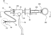
图1是本发明的第一实施方式所涉及的高频治疗工具的立体图。FIG. 1 is a perspective view of a high-frequency treatment tool according to a first embodiment of the present invention.
图2是第一实施方式所涉及的高频治疗工具的主视图。Fig. 2 is a front view of the high-frequency treatment tool according to the first embodiment.
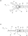
图3(a)是表示治疗部的打开状态的主视图,(b)是表示治疗部的关闭状态的主视图。Fig.3 (a) is a front view which shows the open state of a treatment part, (b) is a front view which shows the closed state of a treatment part.
图4(a)是操作部的主视截面图,(b)是俯视截面图。4( a ) is a front sectional view of the operation unit, and FIG. 4( b ) is a top sectional view.
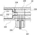
图5是图4(a)的局部放大图。Fig. 5 is a partially enlarged view of Fig. 4(a).
图6是表示设置于主体部的安装部的图。FIG. 6 is a diagram showing a mounting portion provided on a main body portion.
图7是本发明的第二实施方式所涉及的高频治疗工具的操作部的局部截面图,(a)是表示滑块的后退状态的图,(b)是表示滑块的最大前进状态的图,(c)是表示操作电线的松弛状态的图。7 is a partial cross-sectional view of the operating portion of the high-frequency treatment tool according to the second embodiment of the present invention, (a) is a diagram showing the retracted state of the slider, and (b) is a diagram showing the maximum advanced state of the slider. (c) is a diagram showing a slack state of the operating wire.
图8是构成松弛部件的保持件的两个视图,(a)是前端侧的侧视图,(b)是主视图。Fig. 8 is two views of the holder constituting the loose member, (a) is a side view on the front end side, and (b) is a front view.
图9(a)是表示安装松弛部件的状态的主视截面图,(b)是表示松弛部件的安装后的状态的主视截面图。9( a ) is a front sectional view showing a state in which a loose member is attached, and FIG. 9( b ) is a front sectional view showing a state after the loose member is attached.
图10是第二实施方式的变形例所涉及的高频治疗工具中的操作部的局部截面图,(a)是表示滑块的前进限制状态的图,(b)是表示滑块的前进状态的图,(c)是表示操作电线的松弛状态的图。10 is a partial cross-sectional view of the operating portion of the high-frequency treatment tool according to a modified example of the second embodiment, (a) is a diagram showing a state in which the slider is restricted from moving forward, and (b) is a diagram showing a state in which the slider is moving forward; , (c) is a diagram showing the slack state of the operating wire.
具体实施方式 Detailed ways
以下,使用附图对本发明的高频治疗工具的实施方式进行说明。其中,在所有的附图中,对共通的构成元件赋予相同的符号,并在以下的说明中适当省略详细的说明。Hereinafter, embodiments of the high-frequency treatment tool of the present invention will be described using the drawings. However, in all the drawings, the same reference numerals are assigned to common constituent elements, and detailed descriptions will be appropriately omitted in the following description.
第一实施方式first embodiment
图1是本发明的第一实施方式所涉及的高频治疗工具10的立体图。其省略了长条的挠性管50的一部分图示。FIG. 1 is a perspective view of a high-
图2是本实施方式的高频治疗工具10的主视图。另外,在以下的说明中,将与高频治疗工具10的长度方向正对的侧方设为正面方向。FIG. 2 is a front view of the high-
首先,对本实施方式的高频治疗工具10的简要结构进行说明。First, the schematic configuration of the high-
本实施方式的高频治疗工具10具有插入体腔内的挠性管50、自由进退地插通挠性管50的导电性的操作电线30、配置在操作电线30的前端部并且通过高频电流的施加来治疗患部的治疗部60、和附设在挠性管50的基端部的操作部20。The high-
操作部20是对操作电线30进行进退操作来操作治疗部60、并且使操作电线30进行扭矩旋转来使治疗部60进行旋转的机构,其具备主体部22、旋转操作部24和进退操作部26。The
主体部22是安装向治疗部60供给高频电流的高频电流软线70的部分。旋转操作部24是在主体部22的前端侧设置为自由绕轴旋转、并使操作电线30进行扭矩旋转的部分。并且,进退操作部26是在主体部22的基端侧设置为沿轴向自由进退、并使操作电线30进退的部分。The
其次,对本实施方式的高频治疗工具10详细地进行说明。Next, the high-
高频治疗工具10所使用的治疗部60由操作电线30的进退所驱动,并且由操作电线30的扭矩旋转而进行绕轴旋转。治疗部60是通过高频电流的施加来治疗患部的器件。The
治疗部60的具体的构成并无特别限定,在本实施方式中例示有利用连杆机构切开患部的剪刀型的治疗部60。此外,作为治疗部60,可以使用前端部弯曲的刀型、或具备环状的电线的圈套等现有技术中所利用的部件。如后述那样,剪刀型的治疗部60通过操作电线30的进退来驱动连杆机构,并且向患部施加高频的同时将其切开。刀型的治疗部60在将弯曲的前端部钩挂于患部的状态下,向患部施加高频的同时将治疗部60向基端侧牵引,来切开该患部。圈套型的治疗部60通过操作电线30的进退来扩大或者缩小圈套直径,来向患部施加高频的同时将其紧缚。The specific configuration of the
本实施方式的操作电线30是金属制的电线。操作电线30插通由挠性的材料形成的挠性管50。The
挠性管50的材料并无特别限定,可以使用导电性或者非导电性的材料。在使用导电性的材料的情况下,在挠性管50的导电性的内表面涂敷绝缘性材料的薄膜即可。The material of the
另外,作为挠性管50所使用的非导电性材料,能够例示出氟树脂、聚酰亚胺树脂、聚乙烯树脂、聚丙烯树脂、聚氨酯树脂、聚酰胺树脂、聚碳酸酯树脂等树脂材料。其中,优选与挠性管50所插通的内窥镜的钳子孔之间的滑动性优越的氟树脂。In addition, examples of the non-conductive material used for the
治疗部60配置为从挠性管50的前端开口突出。治疗部60、操作电线30以及挠性管50插通内窥镜(未图示)的内腔(lumen)而使用。The
操作部20是牵引或推压操作电线30、或者使该操作电线30进行扭矩旋转的机构。本实施方式的操作部20大致由主体部22、旋转操作部24以及进退操作部26构成。The
主体部22呈中空的筒状,并且在内部插通有操作电线30的基端部。主体部22的轴线方向与操作电线30的延伸方向一致。因此,在本实施方式中,没有特别说明地表述“轴”的情况下,表示操作电线30的延伸方向的含义。The
在主体部22的前端侧设置有旋转操作部24。旋转操作部24与操作电线30卡合,如在图1以及图2中由曲线箭头所示那样,通过使旋转操作部24绕轴旋转而使治疗部60绕轴旋转。A
其中,旋转操作部24设置在操作部20的前端部,具体而言设置在主体部22的前端侧。本实施方式所述的操作部20的“前端部”是指具有规定的宽度的长度区域。Among them, the
在本实施方式的高频治疗工具10中,旋转操作部24设置在操作部20的最前端。In the high-
旋转操作部24呈盖状地安装于主体部22的前端侧。并且,旋转操作部24设置为在主体部22的外周呈环绕状地露出。The
在旋转操作部24的周围,绕操作部20的轴呈环绕状地施以波纹形的滚花加工。Around the
对于本实施方式的高频治疗工具10,操作者能够从绕轴的任意的方向对旋转操作部24进行操作。并且,由于旋转操作部24在主体部22的外周呈环绕状地露出,所以旋转操作部24的旋转行程并无限制。另一方面,在如上述专利文献1的圈套器中的手柄组件那样只有捏手的外周的一部分露出的情况下,难以超过规定的旋转角度(例如180度)而连续地对治疗部60进行旋转操作。即,在专利文献1的圈套器的情况下,当操作者以超过180度的旋转角度对治疗部进行旋转操作时,操作者需要将到达了旋转行程的终端的手指一度离开捏手、并使手指再次移动到旋转行程的始端而再次开始旋转操作。因此,不能连续地操作捏手,进而难以进行治疗部的细微的旋转操作。In the high-
对此,在本实施方式的高频治疗工具10的情况下,由于旋转操作部24的旋转行程并无限制,所以无论治疗部60的旋转角度为多大都能够连续地对治疗部60进行旋转操作。On the other hand, in the case of the high-
另外,如在图1以及图2中由直线箭头所示那样,通过使进退操作部26相对于主体部22的轴主体228沿轴向滑动来对治疗部60进行开关操作。In addition, as shown by the straight arrows in FIGS. 1 and 2 , the
图3是在图2中用虚线表示的区域III的放大图。该图(a)是表示治疗部60的打开状态的主视图,该图(b)是表示治疗部60的关闭状态的主视图。FIG. 3 is an enlarged view of the region III indicated by the dashed line in FIG. 2 . This figure (a) is a front view which shows the open state of the
如图3(a)、(b)所示,在本实施方式的治疗部60中,第一剪刀片61与第二剪刀片62以第一销65为轴相互地开关。As shown in FIG.3 (a), (b), in the
自由滑动地收容于挠性管50中的操作电线30与治疗部60的基端部66连接。若对操作电线30向前端侧(图3各图中的左侧)推压,则第二销64向第一销65被施力,从而连杆机构63使治疗部60打开。The
连杆机构63是包括在第一剪刀片61的基端部形成的第一连杆板611、和在第二剪刀片62的基端部形成的第二连杆板621的四连杆机构。The
另外,通过向前端侧推压操作电线30,如该图(a)所示,第一剪刀片61与第二剪刀片62转动而使前端打开。In addition, by pushing the
图3(a)表示第一剪刀片61与第二剪刀片62的最大打开状态。在使操作电线30前进的情况下,第一剪刀片61与第二剪刀片62处于最大打开状态时的角度被规定为打开角度的上限。FIG. 3( a ) shows the maximum open state of the
另一方面,若将操作电线30向基端侧(图3各图中的右侧)牵引,则如该图(b)所示,第一剪刀片61与第二剪刀片62的前端因连杆机构63的动作而关闭。On the other hand, if the
如图1、2所示,主体部22具备与高频电流软线70电连接的高频施加部226。在高频施加部226中,安装高频电流软线70的电源端子227被设置成向与高频治疗工具10的轴正交的方向突出。As shown in FIGS. 1 and 2 , the
因此,高频电流软线70在与轴线交叉的方向(轴的交叉方向)上与主体部22连接。Therefore, the high-frequency
在本实施方式的高频治疗工具10中,高频施加部226固定于主体部22。若高频电流软线70(参照图2)与高频施加部226连接,则高频电流软钱70因其重量而维持从高频施加部226下垂的状态。由此,在操作旋转操作部24而使治疗部60旋转时,高频电流软线70不会缠绕在旋转操作部24或操作者的手中。In the high-
本实施方式的进退操作部26呈轴对称形状。本实施方式的进退操作部26呈以轴线为旋转中心的旋转对称形状,更具体而言,呈绕轴线地具有环绕状的凹部的筒型形状,以使得能够用操作者的手的中指与食指夹持。并且,进退操作部26在轴向的前端侧与基端侧,分别具有向径向外侧突出的一对凸缘部261。The forward and
另外,本实施方式的高频治疗工具10还具备辅助环262,该辅助环262设置成能够相对于主体部22而绕轴旋转,并且向轴的交叉方向开口。并且,进退操作部26构成为,相对于主体部22的绕轴旋转被固定而沿轴向进退。In addition, the high-
辅助环262是辅助进退操作部26的动作的辅助部,并且是作为用于对进退操作部26进行滑动驱动的支点的部件。The
辅助环262经由转动部264与轴主体228连接成自由绕轴旋转。并且,通过将操作者的拇指插入本实施方式的辅助环262、并且例如用食指和中指夹持进退操作部26而使其向轴向的前后滑动,来进行操作电线30的进退操作。The
在本实施方式的高频治疗工具10中,辅助环262相对于主体部22自由绕轴旋转,并且进退操作部26呈轴对称形状。因此,操作者能够从任意的方向把持高频治疗工具10。In the high-
另一方面,在上述专利文献2的高频治疗工具的情况下,由于操作部的把持方向被限定,所以有时会因操作者的姿势而难以进行旋转以及进退操作。另外,在专利文献2的高频治疗工具中,由于在使操作部绕轴旋转时治疗部旋转,所以在对操作部进行操作时可能会在治疗部产生意外的旋转。On the other hand, in the case of the high-frequency treatment tool disclosed in
对此,在本实施方式的高频治疗工具10的情况下,只要不对旋转操作部24进行旋转操作,治疗部60就不会在对操作部20进行操作时旋转。另外,由于能够从任意的方向来把持进退操作部26,所以能够不受操作者的姿势所影响而对治疗部60进行旋转以及进退操作。On the other hand, in the case of the high-
图4(a)是本实施方式的操作部20的主视截面图,该图(b)是操作部20的俯视截面图。图4(a)、(b)是操作部20的纵截面图。这里,所谓操作部20的纵截面,是指沿轴向切开操作部20的截面。另外,图4(b)是图2的Ⅳ-Ⅳ截面图。FIG. 4( a ) is a front sectional view of the
图5是关于高频施加部226的附近的图4(a)的放大图。FIG. 5 is an enlarged view of FIG. 4( a ) in the vicinity of the high-
图6是表示设置于主体部22的安装部222的图。FIG. 6 is a diagram showing the mounting
在操作部20中,至少前端侧沿轴心方向形成为中空,并且操作电线30的基端部插通于中空的轴心。In the
在操作部20的内部,在操作电线30的基端部的外周设置有金属制的导管(lead pipe)34。操作电线30与导管34电气地、并且机械地接合。即,操作电线30与导管34成为一体而绕轴旋转。Inside the
导管34由金属制成,具有导电性。导管34的壁厚以及外径并无特别限制。通过在操作电线30的外周设置导管34,而提高操作电线30的扭转刚性。The
本实施方式的旋转操作部24由均由绝缘性材料形成的盖部247、卡合部248以及基端嵌合部249组合而构成。The
盖部247是安装在主体部22的前端、并且供操作者进行绕轴旋转操作的构件。The cover part 247 is attached to the front end of the
盖部247呈大致半球状,在轴心处设置有通孔而供操作电线30、导管34以及挠性管50插入其中。挠性管50的基端固定于盖部247。The cover part 247 has a substantially hemispherical shape, and a through hole is provided at the center of the axis, through which the
基端嵌合部249是基端安装于主体部22、在前端安装有盖部247的筒状的部件。换言之,作为将旋转操作部24固定于主体部22的固定部而发挥作用。The base end fitting portion 249 is a cylindrical member whose base end is attached to the
基端嵌合部249形成为其前端侧呈大径地开口、在基端侧呈小径地突出的阶梯圆筒状的突出部244。The base end fitting portion 249 is formed as a stepped cylindrical protruding portion 244 that opens with a large diameter at the front end side and protrudes with a small diameter at the base end side.
盖部247在外周上的不同的多个位置具有爪部246。爪部246钩挂基端嵌合部249。由此,盖部247与基端嵌合部249在绕轴旋转方向以及进退方向上的相对移动均被限制。The cover portion 247 has
卡合部248是收容于基端嵌合部249的前端侧的开口内部、并与盖部247以及基端嵌合部249共同绕轴旋转的构件。The engaging portion 248 is a member accommodated in the opening on the front end side of the proximal fitting portion 249 and rotates about an axis together with the cover portion 247 and the proximal fitting portion 249 .
收容于基端嵌合部249的开口内部的卡合部248相对于基端嵌合部249的绕轴旋转被限制。The engaging portion 248 accommodated inside the opening of the proximal fitting portion 249 is restricted from rotating around the axis relative to the proximal fitting portion 249 .
卡合部248具有沿轴向延伸的狭缝2481,形成为截面呈コ字状(U字状)的柱状。卡合部248相对于导管34沿径向安装。The engaging portion 248 has a slit 2481 extending in the axial direction, and is formed in a columnar shape with a U-shaped (U-shaped) cross section. The engaging portion 248 is mounted radially relative to the
狭缝2481形成为从图4(a)的上方到卡合部248的轴心为止。即,コ字状(U字状)的卡合部248的开口方向为该图的上方。The slit 2481 is formed from above in FIG. 4( a ) to the axis of the engaging portion 248 . That is, the opening direction of the U-shaped (U-shaped) engaging portion 248 is upward in the figure.
卡合部248与导管34卡合并赋予其旋转扭矩,并且使导管34沿轴向滑动。The engaging portion 248 engages with the
在本实施方式的导管34的外周,在卡合部248的内部位置处膨出地形成有矩形柱状的操作电线卡合部37。On the outer periphery of the
卡合部248的狭缝2481的狭缝宽度比操作电线卡合部37的矩形截面的对置面之间距离(操作电线卡合部37的宽度)大,但比操作电线卡合部37的矩形截面的对角距离小。The slit width of the slit 2481 of the engaging portion 248 is larger than the distance between the opposing surfaces of the rectangular section of the operating wire engaging portion 37 (the width of the operating wire engaging portion 37 ), but is larger than that of the operating wire engaging portion 37 . The diagonal distance of the rectangular section is small.
因此,若以狭缝2481中收容了操作电线卡合部37的状态使卡合部248绕轴旋转,则导管34进行扭矩旋转。Therefore, when the engaging portion 248 is rotated around the axis with the operating wire engaging portion 37 accommodated in the slit 2481 , the
在主体部22的前端,设置有朝向前端侧开口的筒状的连接盖230。在连接盖230的基端部形成有内向法兰231。At the front end of the
在内向法兰231的中心的开口232(参照图6)中,插通基端嵌合部249的突出部244。The protruding part 244 of the base end fitting part 249 is inserted into the opening 232 (see FIG. 6 ) at the center of the
在主体部22中,沿径向设置有高频施加部226以及电源端子227。在主体部22的内部,收容有与电源端子227电连接的供电端子229。供电端子229与电源端子227通过金属螺钉(未图示)电气地或者机械地接合。In the
在主体部22中,埋设有金属制的导电管221。导电管221与高频电流软线70(参照图2)电连接、并插通有操作电线30。A metal conductive tube 221 is embedded in the
在操作电线30形成有在与导电管221电连接的状态下进行滑动的筒状的集电部32。A cylindrical
集电部32形成于导管34的外表面,并与导电管221的内表面滑动接触。The
由高频电流软线70供给到电源端子227的高频电流经由导电管221、集电部32、导管34、进而经由操作电线30而向治疗部60施加(参照图2)。The high-frequency current supplied to the
在本实施方式的高频治疗工具10中,均由导电性的金属材料形成的集电部32与导电管221可以滑动并且电气地导通。即,在本实施方式的高频治疗工具10中,实际上不产生摩擦接合地将电源端子227与操作电线30电连接。因此,利用进退操作部26牵引或者推压操作电线30时所需的轴向力不会过大,能够得到电源端子227与操作电线30之间的良好的导电性。In the high-
如图4所示,在导管34的基端,操作电线固定部36膨出地形成。操作电线固定部36以能够扭矩旋转的方式钩挂进退操作部26。通过使进退操作部26相对于轴主体228滑动,对导管34以及操作电线30进行进退操作。As shown in FIG. 4 , at the proximal end of the
在轴主体228形成有沿轴向延伸的狭缝部225。A
本实施方式的进退操作部26由收容于狭缝部225并相对于轴主体228沿轴向滑动的滑块固定件266、和安装在滑块固定件266的外部的滑块265组合而形成。操作电线固定部36埋设于滑块固定件266。The advancing/
如图5所示,在旋转操作部24的基端部(基端嵌合部249)形成有多级的阶梯面241、242。As shown in FIG. 5 , multi-stage stepped surfaces 241 and 242 are formed on the base end portion (base end fitting portion 249 ) of the
另一方面,如图6中由粗线所示,在主体部22的前端部,由连接盖230的内向法兰231、脱落防止部224以及供电端子229来形成供旋转操作部24安装的多级的安装部222。On the other hand, as shown by a thick line in FIG. 6 , at the front end portion of the
并且,在对主体部22安装了基端嵌合部249的突出部244的状态下,多个阶梯面241、242与安装部222面接触。In addition, the plurality of stepped surfaces 241 and 242 are in surface contact with the
在旋转操作部24的基端部(基端嵌合部249)形成的突出部244插通于安装部222。另一方面,在突出部244的周围安装有脱落防止部224。脱落防止部224是用于防止插通于安装部222的突出部244从安装部222脱离的部件。The mounting
本实施方式的脱落防止部224是截面呈コ字状(U字状)、并且与形成于突出部244的周围的凹部243嵌合的键部件。The fall-off preventing
即,如图5所示,在将旋转操作部24的突出部244从前端侧插入了主体部22的开口232(参照图6)的状态下,从径向对突出部244的凹部243安装脱落防止部224。脱落防止部244的直径比开口232的直径大,如同闩那样抑制突出部244的进退方向的移动。由此,安装于主体部22的基端嵌合部249不会与前端侧脱离。That is, as shown in FIG. 5 , in a state where the protruding part 244 of the
脱落防止部224对旋转操作部24(基端嵌合部249)向主体部22的基端侧施加作用力。即,通过将脱落防止部224安装于基端嵌合部249的凹部243,基端嵌合部249的阶梯面241、242以规定的轴向力(垂直阻力)而抵接于阶梯状的安装部222。由此,基端嵌合部249与主体部22具有规定的静摩擦力而相互连接为能够绕轴旋转。The fall-
根据所涉及的构成,在本实施方式的高频治疗工具10中,在利用进退操作部26对操作电线30进行进退操作时、或在操作部20的操作时,治疗部60的朝向不会意外地发生变化。According to this structure, in the high-
在对旋转操作部24进行旋转操作而使操作电线30进行扭矩旋转的情况下,由于挠性管50与操作电线30之间的摩擦损失,导致在由旋转操作部24赋予操作电线30的旋转角中、仅有一部分被赋予治疗部60。换言之,在对旋转操作部24进行旋转操作而使治疗部60指向了所要求的方向时,在挠性管50的内部处于静止的操作电线30成为被施加了规定的扭矩的状态。When the
这里,在使进退操作部26向高频治疗工具10的基端侧滑动而牵引操作电线30的情况下,操作电线30的旋转刚性因加载于操作电线30的张紧力而提高。因此,若牵引操作电线30,则可能会在挠性管50的内部操作电线30产生旋转角复原的情况,从而治疗部60可能会偏离所要求的朝向。Here, when the
对此,在本实施方式的高频治疗工具10中,旋转操作部24与主体部22在多个阶梯面241、242处抵接,通过规定的摩擦力而相互卡合。因此,即使使进退操作部26滑动而牵引操作电线30,由于旋转操作部24与主体部22因静摩擦力而不会相对旋转,所以也不会产生操作电线30的旋转角复原的情况。因此,根据本实施方式的高频治疗工具10,在操作进退操作部26进行患部的切离等治疗的瞬间,治疗部60不会偏离所要求的朝向。In contrast, in the high-
第二实施方式second embodiment
图7是第二实施方式所涉及的高频治疗工具10的操作部20的局部截面图。该图(a)是表示滑块265的后退状态的图,该图(b)是表示滑块265的最大前进状态的图,该图(c)是表示操作电线30的松弛状态的图。FIG. 7 is a partial cross-sectional view of the
图8是构成松弛部件80的保持件82的两个视图。该图(a)是前端侧的侧视图,该图(b)是主视图。FIG. 8 is two views of the
本实施方式的高频治疗工具10还具备松弛部件80,该松弛部件80对沿轴向进行了进退移动的操作电线30向轴向的相反方向施加作用力。The high-
在本实施方式中,松弛部件80对操作电线30施加作用力并不局限于松弛部件80与操作电线30直接地接触而传递作用力的情况。即,包括如本实施方式所述那样,从松弛部件80经由滑块固定件266等其他的部件而间接地对操作电线30传递作用力的情况。In the present embodiment, the application of force to the
本实施方式的高频治疗工具10的特征在于,通过松弛部件80减轻因进退操作部26的操作而赋予操作电线30的张力。由此,在使操作电线30沿前后方向进行了进退的状态下的旋转操作部24的操作性提高。即,在使滑块265进退而对操作电线30沿轴向进行了拉伸或者压缩的情况下,操作电线30所受的张力越大,其扭转刚性越大。因此,通过对操作电线30向进退操作部26进行了进退的方向的相反方向施加作用力,张力得到松弛而操作电线30的扭转刚性恢复到自然状态。由此,在进行旋转操作时应该赋予旋转操作部24的扭矩不会过大。The high-
其中,在本实施方式中,所谓操作电线30的张力是指操作电线30的压缩力和拉伸力这两方面。However, in this embodiment, the tension of the
如使用第一实施方式进行说明的那样,高频治疗工具10通过将进退操作部26和旋转操作部24与主体部22分别地设置,能够不受高频电流软线70的自重的影响地操作治疗部60(参照图1)。这里,如本实施方式所述,还通过由松弛部件80对进行进退操作后的操作电线30的张力进行松弛,来减小对治疗部60进行旋转操作时所需的旋转扭矩,使旋转操作部24的操作性变得更为良好。As described using the first embodiment, the high-
如剪刀型及圈套型所例示那样,使治疗部60处于打开状态下对准患部与角度的情况下,上述的优点变得特别显著。在本实施方式中,作为治疗部60例示出剪刀型(参照图3)。The above-mentioned advantages become particularly remarkable when the
即,本实施方式的治疗部60具有通过由进退操作部26使操作电线30进退而相互开闭的多个剪刀片(第一剪刀片61以及第二剪刀片62)。That is, the
并且,在操作电线30沿轴向向前进方向或者后退方向移动而第一剪刀片61以及第二剪刀片62打开了的状态下,松弛部件80对操作电线30向后退方向或者前进方向施加作用力。And, in the state where the
更具体而言,在图7(a)所示的滑块265的后退状态中,由于操作电线30被向基端侧牵引,所以第一剪刀片61与第二剪刀片62处于相互关闭的关闭状态(参照图3(b))。More specifically, in the retracted state of the
并且,若滑块265前进,则操作电线30被向前端侧推压。由此,第一剪刀片61与第二剪刀片62以第一销65为中心相互绕轴旋转而成为前端打开了的打开状态(参照图3(a))。Then, when the
另外,作为剪刀型的治疗部60,并不局限于图3各图所示的绕销旋转式的方式,还可以是第一剪刀片61与第二剪刀片62相互保持平行的状态下沿挠性管50的径向接触分离的平行滑动式的方式。In addition, as the scissor-shaped
图3(a)以及图7(b)表示使操作电线30进退后第一剪刀片61与第二剪刀片62的打开量成为最大的最大打开状态。3( a ) and FIG. 7( b ) show the maximum open state in which the opening amount of the
然后,如图7(c)所示,从治疗部60的最大打开状态开始,利用松弛部件80的作用力使操作电线30向后退方向或者前进方向(本实施方式的情况为后退方向)移动,第一剪刀片61以及第二剪刀片62变为打开量(打开宽度)比最大打开状态减少了的中间打开状态(未图示)。其中,治疗部60的中间打开状态是指除最大打开状态和完全的关闭状态以外的其他的状态。Then, as shown in FIG. 7( c), from the maximum open state of the
使用图7以及图8对本实施方式的高频治疗工具10进一步详细地进行说明。The high-
更具体而言,松弛部件80由纵截面呈横倒的方形U字状(コ字状)的保持件82和施力弹簧84组合而形成。即松弛部件80可以像本实施方式那样地由多个部件构成,也可以由一个部件构成。More specifically, the slack member 80 is formed by combining a
施力弹簧84为螺旋弹簧。施力弹簧84的卷径(外径)比主体部22的狭缝部225的开口宽度小。施力弹簧84安装于导管34的周围,并且朝向导管34的延伸方向、即操作部20的轴向(图7各图的左右方向)弹性地伸缩。The urging
施力弹簧84的基端841可以相对于导管34或者滑块固定件266而固定,也可以相互不固定。The
保持件82为如下部件,即,在进退操作部26与主体部22沿轴向接近为规定以上的情况下,保持件82沿轴向压缩施力弹簧84,从而对进退操作部26向离开主体部22的方向施加作用力。The
保持件82在朝向操作部20的前端侧而安装的前方侧(图8(b)的左侧)具备平坦的按压面821,在后方侧(图8(b)的右侧)具有开口部822。在上下隔着开口部822的一对大致平行的弹性片823上,朝向上下方向的外侧而突出地形成有挂钩爪824。挂钩爪824的开口侧(后方侧)的倾斜角度比深入侧(前方侧)的倾斜角度缓和。The
在弹性片823的开口侧的内侧端部形成有倾斜部826,朝向后方侧而开口部822的开口宽度扩大。An
保持件82具有向下方开口的沟部825。沟部825的沟宽度比导管34的外径大、且比施力弹簧84的卷径(外径)小。The
图9(a)是表示安装松弛部件80(保持件82以及施力弹簧84)的状态的主视截面图,该图(b)是表示松弛部件80的安装后的状态的主视截面图。在该图(a)中,用双点划线表示自然状态的保持件82,用实线表示挂钩爪824沉入的状态的保持件82。9( a ) is a front cross-sectional view showing a state where the loosening member 80 (
在图9各图中,示出了滑块固定件266、埋设于滑块固定件266的操作电线固部定36、以操作电线固定部36为基端而向前端侧延伸的导管34、以及插通于导管34的操作电线30。滑块265以及主体部22省略图示。In each figure of FIG. 9 , the
首先,在导管34的前端侧(图9的左侧)安装施力弹簧84。施力弹簧84被安装成能够相对于导管34滑动。First, an urging
其次,在使保持件82的按压面821朝向前端侧的状态下,将导管34插入沟部825。由此,如图9(a)所示,保持件82被安装成横跨导管34。Next, the
接下来,在从上下方向按压保持件82的弹性片823而使挂钩爪824沉入按压面821的状态下,将保持件82插入滑块固定件266的一对腕部267之间。此时,由于挂钩爪824的开口侧(后方侧)缓和地倾斜,所以只要将保持件82向后方推压,挂钩爪824就会被滑块固定件266的前端部268施力而沉入该前端部268,从而弹性片823向内侧弯曲。由此,挂钩爪824能够通过一对前端部268之间。Next, the
这里,由于在弹性片823的开口侧的内侧端部形成有倾斜部826,所以如图9(a)所示,在弹性片823弯曲的状态下,倾斜部826与导管34平行。此时,倾斜部826彼此之间的开口宽度比施力弹簧84的卷径(外径)大,保持件82沿施力弹簧84的外周进入腕部267之间。Here, since the
如图9各图所示,在滑块固定件266的前端部268与腕部267之间形成有台阶部269。并且,如该图(b)所示,若挂钩爪824通过台阶部269,则由弹性片823的弹性恢复力而挂钩爪824再次比按压面821突出。由此,利用挂钩爪824与台阶部269的卡合来限制保持件82从滑块固定件266脱离。As shown in each figure of FIG. 9 , a
如上所述,保持件82以及施力弹簧84安装于滑块固定件266的内部。As described above, the
返回图7,对本实施方式的高频治疗工具10的松弛部件80的动作详细地进行说明。Returning to FIG. 7 , the operation of the loosening member 80 of the high-
保持件82以及施力弹簧84以收容于操作部20的狭缝部225的状态,安装于滑块固定件266的内部。The
另一方面,在主体部22中,从进退操作部26的前端侧朝向狭缝部225的内部、沿轴向突出地形成有后方突起223。后方突起223形成为从基端侧起宽度缩小的锥形状。后方突起223的基端侧的端面平坦,并且与保持件82的按压面821平行。On the other hand, in the
如图7(a)所示,保持件82以及施力弹簧84安装于主体部22与进退操作部26之间。换言之,松弛部件80(保持件82以及施力弹簧84)被主体部22与进退操作部26弹性地夹持。As shown in FIG. 7( a ), the
在图7(a)所示的滑块265的后退状态下,施力弹簧84为自然长度,不向主体部22以及进退操作部26施加作用力。In the backward state of the
此时,如上所述,治疗部60的第一剪刀片61与第二剪刀片62关闭(参照图3(b))。在该状态下,治疗部60以及挠性管50插通于内窥镜的钳子孔(未图示)。At this time, as described above, the
这里,内窥镜通常具备多个钳子孔。对于各钳子孔,除了本实施方式的高频治疗工具10以外,还可以插通有纤维内窥镜或CCD(ChargeCoupled Device,电荷耦合器件)相机等光学系统。另外,有时在内窥镜的前端安装圆筒状的罩。通过在内窥镜的前端使罩突出地安装,能够以患部与光学系统的距离保持一定的状态来固定两者的相对位置。Here, the endoscope usually has a plurality of forceps holes. For each forceps hole, in addition to the high-
若治疗部60从内窥镜的钳子孔的前端突出,则能够利用光学系统观察罩的内部的治疗部60的位置以及旋转角度。并且,一边利用光学系统观察治疗部60,一边对旋转操作部24进行扭矩旋转而使治疗部60的旋转角度适宜于患部。具体而言,进行以下所述的治疗部60的旋转操作。If the
首先,操作者将一根手指(拇指)插通于辅助环262(参照图1),用其他的手指夹持滑块265,如图7(b)所示那样地使进退操作部26前进到可移动范围的最前方。将该状态称为进退操作部26的最前进状态。First, the operator inserts one finger (thumb) through the auxiliary ring 262 (see FIG. 1 ), holds the
在进退操作部26的最前进状态下,操作电线30与进退操作部26共同前进,第一剪刀片61以及第二剪刀片62形成最大打开状态(参照图3(a))。并且,用光学系统观察到第一剪刀片61和第二剪刀片62所呈的V字形状。In the most advanced state of the forward and
另外,在剪刀型的治疗部60的情况下,由于在其关闭状态下的宽度方向(图3(b)的上下方向)与厚度方向(该图的纸面前后方向)的尺寸相互接近,所以利用光学系统目测观察时,通常难于判断治疗部60的旋转角度。因此,可以如本实施方式那样,在打开治疗部60的状态下利用光学系统观察其旋转角度。In addition, in the case of the scissors-shaped
此时,保持件82被后方突起223向基端侧(图7(b)的右侧)按压,从而弹性片823触碰滑块固定件266。这里,由于施力弹簧84的自然长度比弹性片823长,所以因保持件82被滑块固定件266推压而施力弹簧84被弹性地压缩。由此,施力弹簧84经由滑块固定件266以及导管34、对操作电线30向轴向的后方施加作用力。但是,在操作者的手指把持进退操作部26的期间,进退操作部26在最前进状态下静止,施力弹簧84保持压缩状态。At this time, the
其次,操作者将手指从进退操作部26离开。由此,施力弹簧84因弹性恢复力而使保持件82与滑块固定件266向相互分离的方向滑动。即,如图7(c)所示,使滑块固定件266后退。Next, the operator releases his finger from the forward/
这里,在进退操作部26的最前进状态下施力弹簧84所得到的弹性恢复力,比操作电线30、导管34及滑块固定件266、与挠性管50及主体部22的最大静摩擦力的总和大。因此,只要操作者将手指从进退操作部26离开,进退操作部26就会略微后退。Here, the elastic restoring force obtained by the urging
那么,被推压至最前进状态的操作电线30的张力(压缩力)的至少一部分解除,从而操作电线30实质上变成松弛的状态。Then, at least a part of the tension (compressive force) of the
其中,本实施方式中,将进退操作部26位于除了可移动范围的最前方以及最后方以外的中间位置的状态,称为操作电线30的松弛状态。However, in this embodiment, the state in which the forward/
在图7(c)所示的操作电线30的松弛状态下,由于第一剪刀片61与第二剪刀片62(参照图3(a))处于相互打开的状态,所以能够利用光学系统观察治疗部60的朝向。另一方面,操作电线30的松弛状态下的第一剪刀片61与第二剪刀片62的打开宽度比最大打开状态下的最大打开宽度小。因此,可防止第一剪刀片61以及第二剪刀片62的前端与罩的内壁面干扰。In the relaxed state of the
由以上可知,根据本实施方式的高频治疗工具10,即使操作者使进退操作部26前进到最前进状态,也能够通过将其手指从进退操作部26离开而使治疗部60的打开宽度自动地减少、进而使操作电线30变成松弛状态。因此,接下来在操作者操作旋转操作部24时操作电线30的张力解除,所以能够无需过大的旋转扭矩地对旋转操作部24良好地进行旋转操作。此外,由于在旋转操作部24进行旋转操作时,治疗部60处于中间打开状态,所以基于光学系统的可视性并无损失,进而能够避免罩与治疗部60的物理性的干扰。As can be seen from the above, according to the high-
特别地,在进退操作部26的可移动范围大、治疗部60变成最大打开状态并且进退操作部26能够前进的情况下,在对进退操作部26进行前进操作时,有时会向操作电线30施加大的压缩力。在上述情况下,如本实施方式那样,通过利用松弛部件80减轻或者解除操作电线30的压缩力,能够最大程度地减轻旋转操作部24所需的旋转扭矩。In particular, when the movable range of the forward and
图10是表示第二实施方式的高频治疗工具10的变形例的局部截面图。本变形例的高频治疗工具10的松弛部件80包括:以规定的钩挂力钩挂操作电线30来限制进退操作部26的进退移动的保持件82;和被保持件82与进退操作部26弹性地夹持的施力部件(施力弹簧84)。并且,对于本变形例的高频治疗工具10,在对进退操作部26向轴向施加比规定的钩挂力大的负载时,保持件82与操作电线30的钩挂被解除,从而进退操作部26进退移动。FIG. 10 is a partial cross-sectional view showing a modified example of the high-
保持件82对操作电线30直接地或者间接地进行钩挂。在本变形例的情况下,在高频治疗工具10中,保持件82嵌合安装于插通有操作电线30的导管34。并且,保持件82相对于导管34摩擦地滑动。图10(a)表示保持件82与导管34(操作电线30)进行了钩挂的进退操作部26的前进限制状态。如该图所示,在进退操作部26开始从后退位置向前端侧(该图的左侧)移动的状态下,保持件82因静摩擦力而相对于导管34静止,施力弹簧84被压缩。The
保持件82与操作电线30的钩挂,可以是如上所述的摩擦性钩挂,也可以是能够因向轴向的规定的外力而脱离的凹凸嵌合。The hooking between the
若进退操作部26进一步向前端侧移动,则施力弹簧84的压缩量增大。然后,若施力弹簧84的弹性恢复力与保持件82和导管34之间的最大静摩擦力达到平衡,则如该图(b)所示,保持件82相对于导管34摩擦地滑动而向前端侧移动。该图表示进退操作部26的前进状态。When the forward/
对于本变形例的保持件82,在被推压到滑块固定件266的腕部267的最后方的状态下,按压面821向比滑块固定件266的前端部268更靠前端侧突出(参照图9)。In the
若进退操作部26从图10(b)的状态进一步向前端侧移动,而保持件82的按压面821抵接于主体部22,则施力弹簧84对滑块固定件266施加朝向基端侧的弹力(参照图10(c))。If the forward and
由此,进退操作部26从最前进状态略微向基端侧返回,操作电线30的推压力的一部分消失,操作电线30变为松弛状态。即,图10(c)表示操作电线30的松弛状态。此时,第一剪刀片61与第二剪刀片62(参照图3(a))从最大张开状态变成略微关闭的状态。由此,能够减小旋转操作部24的旋转扭矩,并且能够避免治疗部60(参照图1)与罩的光学性的或者物理性的干涉。As a result, the forward/
本变形例的高频治疗工具10在插通弯曲或者屈曲(以下,不区分两者,均称为弯曲)的体腔时发挥特有的效果。The high-
这里,在体腔(或者预先插通于体腔的探针的内腔)弯曲的情况下,若将高频治疗工具10的挠性管50与操作电线30(以下,参照图1)插入其中,则操作电线30相对于挠性管50相对地前进。这是由于与挠性管50的弯曲的内侧相比,插通于挠性管50的操作电线30的路径长度更长。由此,随着挠性管50及操作电线30的弯曲,在挠性管50的前端的治疗部60保持关闭状态下,操作电线30相对于挠性管50前进,进而进退操作部26向前端侧被拉出。Here, when the body cavity (or the lumen of the probe inserted in advance in the body cavity) is curved, if the
另一方面,对于本变形例的高频治疗工具10,如图10(a)所示,即使向前端侧略微拉出进退操作部26而使施力弹簧84被压缩,与导管34摩擦地卡止的保持件82也会成为制动器来限制进退操作部26的前进。因此,对于本变形例的高频治疗工具10,即使将挠性管50以及操作电线30插入弯曲的体腔或内腔,进退操作部26也不会移动到狭缝部225的最前端位置。即,与保持件82和导管34之间的钩挂力相当的最大静摩擦力,比在挠性管50以及操作电线30弯曲的情况下的进退操作部26在前进位置中的施力弹簧84的弹性恢复力大。On the other hand, for the high-
由此,即使在向弯曲的体腔或内腔中插入高频治疗工具10的情况下,当治疗部60到达患部的附近时,也会在进退操作部26中保留用于对治疗部60进一步进行前进操作而打开治疗部60的行程。Thus, even when the high-
对此,使用者使进退操作部26前进的外力与保持件82和导管34之间的钩挂力相比足够地大。因此,如图10(b)所示,在对进退操作部26进行前进操作的情况下,保持件82与滑块固定件266共同相对于导管34前进。由此,操作电线30相对于固定于主体部22的挠性管50而相对地前进,治疗部60变成打开状态。In contrast, the user's external force to advance the forward/
进而,在进退操作部26到达最前进状态的情况下,如图10(c)所示,进退操作部26因施力弹簧84的反作用力而略微地向基端侧返回,如上所述,操作电线30变成松弛状态。Furthermore, when the advancing and retreating
如上所述,根据本变形例的高频治疗工具10,即使在将挠性管50插入弯曲的体腔或内腔的情况下,由于松弛部件80适当地限制进退操作部26的前进,所以发挥了进退操作部26以及松弛部件80的作用。As described above, according to the high-
本申请主张于2009年5月21日提出的日本申请特愿2009-123077的优先权,并在此引用其公开的全部内容。This application claims the priority of Japanese application Japanese Patent Application No. 2009-123077 for which it applied on May 21, 2009, and uses the whole content of the indication here.
Claims (14)
Applications Claiming Priority (3)
| Application Number | Priority Date | Filing Date | Title |
|---|---|---|---|
| JP2009-123077 | 2009-05-21 | ||
| JP2009123077 | 2009-05-21 | ||
| PCT/JP2010/003111 WO2010134273A1 (en) | 2009-05-21 | 2010-05-06 | High-frequency treatment device |
Publications (2)
| Publication Number | Publication Date |
|---|---|
| CN102427770A true CN102427770A (en) | 2012-04-25 |
| CN102427770B CN102427770B (en) | 2014-05-07 |
Family
ID=43125967
Family Applications (1)
| Application Number | Title | Priority Date | Filing Date |
|---|---|---|---|
| CN201080021839.3A Expired - Fee Related CN102427770B (en) | 2009-05-21 | 2010-05-06 | High Frequency Therapy Tools |
Country Status (8)
| Country | Link |
|---|---|
| US (1) | US20120046661A1 (en) |
| EP (1) | EP2433582A4 (en) |
| JP (1) | JP5500170B2 (en) |
| KR (1) | KR20120036316A (en) |
| CN (1) | CN102427770B (en) |
| AU (1) | AU2010250646A1 (en) |
| BR (1) | BRPI1012999A2 (en) |
| WO (1) | WO2010134273A1 (en) |
Cited By (5)
| Publication number | Priority date | Publication date | Assignee | Title |
|---|---|---|---|---|
| CN103565514A (en) * | 2012-08-01 | 2014-02-12 | 四川锦江电子科技有限公司 | Double-control bent spiral electrophysiological catheter |
| CN105228544A (en) * | 2013-06-03 | 2016-01-06 | 住友电木株式会社 | High-frequency treatment tool |
| WO2019128955A1 (en) * | 2017-12-25 | 2019-07-04 | 杭州安杰思医学科技有限公司 | Device for operating electrosurgical instrument |
| CN111954502A (en) * | 2017-10-13 | 2020-11-17 | 科瑞欧医疗有限公司 | Electrosurgical Resection Tool |
| WO2022141769A1 (en) * | 2020-12-31 | 2022-07-07 | 杭州堃博生物科技有限公司 | Radio-frequency ablation catheter and radio-frequency ablation system |
Families Citing this family (10)
| Publication number | Priority date | Publication date | Assignee | Title |
|---|---|---|---|---|
| KR101298690B1 (en) * | 2011-01-25 | 2013-08-21 | 신경민 | Medical Snare |
| KR101356607B1 (en) * | 2012-06-26 | 2014-02-03 | 신경민 | High-frequency treatment device |
| KR101434628B1 (en) * | 2013-01-30 | 2014-08-27 | 주식회사 세종메디칼 | Medical snare device |
| JP6698311B2 (en) * | 2015-10-19 | 2020-05-27 | タカラベルモント株式会社 | controller |
| KR101979073B1 (en) * | 2017-01-09 | 2019-05-15 | 인제대학교 산학협력단 | Unipolar electrosurgical pencil with flexible electrode and rotating cord |
| GB2567469A (en) * | 2017-10-13 | 2019-04-17 | Creo Medical Ltd | Electrosurgical apparatus |
| KR102440229B1 (en) * | 2021-09-15 | 2022-09-02 | 김창보 | Endoscope forceps with integrated wire holder |
| KR102617009B1 (en) * | 2021-12-15 | 2023-12-21 | 강릉원주대학교산학협력단 | Endoscopic hot biopsy forceps that can be sterilized with high-pressure steam |
| KR102838546B1 (en) * | 2022-04-26 | 2025-07-25 | 엘라보메디 주식회사 | Bipolar forceps with rotatable operation |
| KR102901862B1 (en) * | 2023-06-22 | 2025-12-18 | 주식회사 파인메딕스 | Hemostatic forceps for endoscope |
Citations (5)
| Publication number | Priority date | Publication date | Assignee | Title |
|---|---|---|---|---|
| JP2004113546A (en) * | 2002-09-27 | 2004-04-15 | Hironori Yamamoto | High-frequency snare |
| US20070198011A1 (en) * | 2006-02-20 | 2007-08-23 | Pentax Corporation | Bipolar high-frequency treatment tool for endoscope |
| JP2007215787A (en) * | 2006-02-17 | 2007-08-30 | Pentax Corp | High frequency knife for endoscope |
| JP2007325721A (en) * | 2006-06-07 | 2007-12-20 | Olympus Medical Systems Corp | Endoscopic treatment tool |
| CN101278859A (en) * | 2007-04-06 | 2008-10-08 | 奥林巴斯医疗株式会社 | Endoscope Treatment Instruments |
Family Cites Families (9)
| Publication number | Priority date | Publication date | Assignee | Title |
|---|---|---|---|---|
| US6235026B1 (en) | 1999-08-06 | 2001-05-22 | Scimed Life Systems, Inc. | Polypectomy snare instrument |
| JP4420593B2 (en) * | 2002-07-29 | 2010-02-24 | Hoya株式会社 | Bipolar high-frequency treatment instrument for endoscope |
| JP2005198735A (en) * | 2004-01-14 | 2005-07-28 | Pentax Corp | Operation part of high-frequency treatment instrument for endoscope |
| US8414574B2 (en) * | 2006-06-01 | 2013-04-09 | Hoya Corporation | Treatment instrument having a front-end treatment member |
| JP4441509B2 (en) * | 2006-06-22 | 2010-03-31 | Hoya株式会社 | Endoscopic treatment tool |
| JP5053749B2 (en) * | 2007-08-02 | 2012-10-17 | オリンパスメディカルシステムズ株式会社 | Operation unit structure of endoscope treatment tool |
| JP4959518B2 (en) | 2007-11-16 | 2012-06-27 | 株式会社Nykシステムズ | 3D CG object interference check program |
| JP5158952B2 (en) * | 2008-04-08 | 2013-03-06 | 有限会社リバー精工 | Monopolar high-frequency treatment instrument for endoscope |
| JP5167949B2 (en) * | 2008-05-23 | 2013-03-21 | 住友ベークライト株式会社 | Endoscopic high-frequency treatment instrument |
-
2010
- 2010-05-06 CN CN201080021839.3A patent/CN102427770B/en not_active Expired - Fee Related
- 2010-05-06 AU AU2010250646A patent/AU2010250646A1/en not_active Abandoned
- 2010-05-06 US US13/266,338 patent/US20120046661A1/en not_active Abandoned
- 2010-05-06 WO PCT/JP2010/003111 patent/WO2010134273A1/en not_active Ceased
- 2010-05-06 BR BRPI1012999A patent/BRPI1012999A2/en not_active IP Right Cessation
- 2010-05-06 JP JP2011514310A patent/JP5500170B2/en not_active Expired - Fee Related
- 2010-05-06 EP EP10777513.2A patent/EP2433582A4/en not_active Withdrawn
- 2010-05-06 KR KR1020117030474A patent/KR20120036316A/en not_active Withdrawn
Patent Citations (5)
| Publication number | Priority date | Publication date | Assignee | Title |
|---|---|---|---|---|
| JP2004113546A (en) * | 2002-09-27 | 2004-04-15 | Hironori Yamamoto | High-frequency snare |
| JP2007215787A (en) * | 2006-02-17 | 2007-08-30 | Pentax Corp | High frequency knife for endoscope |
| US20070198011A1 (en) * | 2006-02-20 | 2007-08-23 | Pentax Corporation | Bipolar high-frequency treatment tool for endoscope |
| JP2007325721A (en) * | 2006-06-07 | 2007-12-20 | Olympus Medical Systems Corp | Endoscopic treatment tool |
| CN101278859A (en) * | 2007-04-06 | 2008-10-08 | 奥林巴斯医疗株式会社 | Endoscope Treatment Instruments |
Cited By (9)
| Publication number | Priority date | Publication date | Assignee | Title |
|---|---|---|---|---|
| CN103565514A (en) * | 2012-08-01 | 2014-02-12 | 四川锦江电子科技有限公司 | Double-control bent spiral electrophysiological catheter |
| CN103565514B (en) * | 2012-08-01 | 2015-05-06 | 四川锦江电子科技有限公司 | Double-control bent spiral electrophysiological catheter |
| CN105228544A (en) * | 2013-06-03 | 2016-01-06 | 住友电木株式会社 | High-frequency treatment tool |
| TWI624245B (en) * | 2013-06-03 | 2018-05-21 | 住友電木股份有限公司 | High-frequency treatment instrument |
| CN111954502A (en) * | 2017-10-13 | 2020-11-17 | 科瑞欧医疗有限公司 | Electrosurgical Resection Tool |
| CN111954502B (en) * | 2017-10-13 | 2024-11-19 | 科瑞欧医疗有限公司 | Electrosurgical Resection Tools |
| US12396784B2 (en) | 2017-10-13 | 2025-08-26 | Creo Medical Limited | Electrosurgical resector tool |
| WO2019128955A1 (en) * | 2017-12-25 | 2019-07-04 | 杭州安杰思医学科技有限公司 | Device for operating electrosurgical instrument |
| WO2022141769A1 (en) * | 2020-12-31 | 2022-07-07 | 杭州堃博生物科技有限公司 | Radio-frequency ablation catheter and radio-frequency ablation system |
Also Published As
| Publication number | Publication date |
|---|---|
| AU2010250646A1 (en) | 2011-11-17 |
| JP5500170B2 (en) | 2014-05-21 |
| KR20120036316A (en) | 2012-04-17 |
| EP2433582A1 (en) | 2012-03-28 |
| US20120046661A1 (en) | 2012-02-23 |
| CN102427770B (en) | 2014-05-07 |
| EP2433582A4 (en) | 2014-02-12 |
| WO2010134273A1 (en) | 2010-11-25 |
| JPWO2010134273A1 (en) | 2012-11-08 |
| BRPI1012999A2 (en) | 2018-01-16 |
Similar Documents
| Publication | Publication Date | Title |
|---|---|---|
| CN102427770B (en) | High Frequency Therapy Tools | |
| US12343067B2 (en) | Electrosurgical device | |
| KR101061726B1 (en) | Operating mechanism for flexible endoscope device | |
| US6165191A (en) | Ultrasonic treating tool | |
| JP5292430B2 (en) | Endoscopic treatment tool | |
| EP1518492B1 (en) | Endoscopic device with a handle | |
| US8545395B2 (en) | Endoscopically inserting surgical tool | |
| JP2019526401A (en) | Endoscopic suturing system having an external instrument channel | |
| CN105011893A (en) | Endoscope, and treatment instrument for endoscope | |
| KR20100110801A (en) | Surgical instrument | |
| JP4698864B2 (en) | Multifunction surgical instrument | |
| US20220117619A1 (en) | Micro-invasive surgical device and methods of use | |
| US20250151987A1 (en) | Endoscope treatment tool and endoscope system | |
| JP2007151615A (en) | Biological suture tool | |
| US20140336645A1 (en) | Forceps with continuous latch | |
| HK1168017A (en) | High-frequency treatment device | |
| JP4777385B2 (en) | Operation aids for endoscopic treatment tools | |
| CN111200983B (en) | Medical device | |
| CN112236091A (en) | Treatment tool | |
| JP2001128984A (en) | Lithomyl | |
| JP2017176670A (en) | Clip removing device | |
| JPH09533A (en) | Endoscope treatment tool |
Legal Events
| Date | Code | Title | Description |
|---|---|---|---|
| C06 | Publication | ||
| PB01 | Publication | ||
| C10 | Entry into substantive examination | ||
| SE01 | Entry into force of request for substantive examination | ||
| REG | Reference to a national code |
Ref country code: HK Ref legal event code: DE Ref document number: 1168017 Country of ref document: HK |
|
| C14 | Grant of patent or utility model | ||
| GR01 | Patent grant | ||
| CF01 | Termination of patent right due to non-payment of annual fee |
Granted publication date: 20140507 Termination date: 20150506 |
|
| EXPY | Termination of patent right or utility model | ||
| REG | Reference to a national code |
Ref country code: HK Ref legal event code: WD Ref document number: 1168017 Country of ref document: HK |